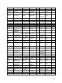
1
Rocky Mountain
Space Grant
Observatory
Final Report
Table of Contents
Table of Contents ............................................................................................................................ 1
Abstract ........................................................................................................................................... 4
Group Members .............................................................................................................................. 5
1.0
Introduction .......................................................................................................................... 6
2.0
Problem Statement ............................................................................................................... 6
3.0
Project Organization ............................................................................................................ 6
3.1 Engineering Team ............................................................................................................ 6
3.2 Semester Timeline ............................................................................................................ 6
3.1 Cost Estimation ................................................................................................................ 8
4.0
Weather Subsystem ............................................................................................................ 12
4.1 Sensors ........................................................................................................................... 12
4.1.1
TE525 Rain Gauge .................................................................................................. 12
4.1.2
03101 R.M. Wind Sensor........................................................................................ 12
4.1.3
HMP45C Temperature/Humidity Sensor ............................................................... 13
4.1.4
Sensor Manuals ....................................................................................................... 14
4.1.5
Weather Research ................................................................................................... 14
4.1.6
Sensor Set Up.......................................................................................................... 14
4.1.7
Sensor Power .......................................................................................................... 15
4.2 Software ......................................................................................................................... 15
4.2.1
Weather Program .................................................................................................... 16
4.2.2
Dome Hatch Control ............................................................................................... 24
4.3 GUI (RSView32)............................................................................................................ 25
4.3.1 Creating Tags ............................................................................................................... 25
4.3.2 Data Logging ............................................................................................................... 26
5.0
Dome Operations Subsystem ............................................................................................. 26
5.1 Summary of Design Process .......................................................................................... 26
5.1.1 Design One................................................................................................................... 28
5.1.2 Design Two .................................................................................................................. 29
5.1.3 Summary of Final Results............................................................................................ 29
5.2 Problem Analysis ................................................................................................................ 30
5.2.1 Review of Problem ...................................................................................................... 30
5.2.2 Design Considerations ................................................................................................. 30
5.2.2.1 Limit Switches ...................................................................................................... 31
5.2.2.2 Motor Delays ........................................................................................................ 31
5.2.3 Summary of Specifications .......................................................................................... 32
5.3 Detailed Design, Schematics, and Layout .......................................................................... 32
5.3.1 Motor/Sensor................................................................................................................ 32
5.3.1.1 Motor..................................................................................................................... 32
5.3.1.2 Sensors .................................................................................................................. 35
5.3.2 PLC .............................................................................................................................. 37
5.3.2.1 PLC Hardware ...................................................................................................... 37
5.3.2.2 PLC System Overview .......................................................................................... 38
1
5.3.2.2 PLC Code .............................................................................................................. 39
5.4 Project Implementation/Operation and Assessment ........................................................... 46
5.4.1 Current Implementation ............................................................................................... 46
5.4.2 Finishing Work Process ............................................................................................... 46
5.4.2.1 Power Failure ........................................................................................................ 46
5.4.2.2 Close Shutter/ Weather ......................................................................................... 46
5.4.2.3 Sensors .................................................................................................................. 47
5.4.2.4 Dome Rotation ...................................................................................................... 47
6.0
Telescope Subsystem ......................................................................................................... 45
6.1 Existing Hardare/Conditions .......................................................................................... 45
6.1.1
Telescope Subsystem .............................................................................................. 45
6.1.2
Location/Operating Conditions............................................................................... 47
6.2 Design Constraints ......................................................................................................... 47
6.2.1
Operating Software ................................................................................................. 47
6.2.2
Vibration Control .................................................................................................... 48
6.3 Designs ........................................................................................................................... 48
6.3.1
Software Selection .................................................................................................. 48
6.3.2
Camera Selection .................................................................................................... 49
6.3.3
Vibration Control .................................................................................................... 50
6.3.4
Cable Interfacing..................................................................................................... 50
6.4 Implementation............................................................................................................... 52
6.4.1
Computer Software Configuration .......................................................................... 52
6.4.2
Camera Installation ................................................................................................. 53
6.4.3
Floor Mounting/Vibration Control ......................................................................... 54
6.4.4
Telescope Alignment .............................................................................................. 54
6.4.5
Equatorial Mount .................................................................................................... 55
7.0 Final Scope of Work Statement .............................................................................................. 57
7.1 What Has Been Done .......................................................................................................... 57
7.2 Lessons Learned.................................................................................................................. 58
7.3 Power Installation Issues..................................................................................................... 59
8.0 Maintenance ............................................................................................................................ 60
8.1 Duties .................................................................................................................................. 60
8.2 Dome Instructions ............................................................................................................... 61
9.0 Conclusion .............................................................................................................................. 64
10.0 Special Thanks to Sponsors .................................................................................................. 64
2
List of Figures
FIGURE 1: OVERALL SYSTEM ........................................................................................................... 7
FIGURE 2: GANTT CHARTS ............................................................................................................... 8
FIGURE 3: SINE WAVE TO SQUARE WAVE CIRCUIT ....................................................................... 11
FIGURE 4: 5 VOLT VOLTAGE REGULATOR ..................................................................................... 13
FIGURE 5: 12 VOLT VOLTAGE REGULATOR ................................................................................... 13
FIGURE 6: WEATHER PROGRAM LADDER LOGIC ............................................................................ 21
FIGURE 7: PLC VARIABLE/MEMORY LIST ..................................................................................... 22
FIGURE 8: INDUCTION MOTOR ....................................................................................................... 31
FIGURE 9: SOFT STARTER .............................................................................................................. 31
FIGURE 10: VOLTAGE VS. TIME GRAPH ......................................................................................... 32
FIGURE 11: SOFT START WIRE DIAGRAM ...................................................................................... 32
FIGURE 12: HARDWARE SETUP ...................................................................................................... 34
FIGURE 13: SENSOR CIRCUIT ......................................................................................................... 34
FIGURE 14: PLC FRONT ................................................................................................................. 35
FIGURE 15: ERROR CORRECTION ................................................................................................... 36
FIGURE 16: ROUTINE CHECK ......................................................................................................... 37
FIGURE 17: ROTATION CODE ......................................................................................................... 41
FIGURE 18: SHUTTER CODE ........................................................................................................... 43
FIGURE 19: TELESCOPE SYSTEM BLOCK DIAGRAM ....................................................................... 47
FIGURE 20: REMOTE HANDBOX ..................................................................................................... 49
FIGURE 21: ENVISGE IMAGING ....................................................................................................... 49
FIGURE 22: INTERFACE FLOW DIAGRAM ....................................................................................... 51
FIGURE 23: SETTING UP LOCATION SETTINGS ............................................................................... 53
FIGURE 24: COM PORT SETTINGS ................................................................................................... 53
FIGURE 25: SENSOR CIRCUIT FRONT .............................................................................................. 56
FIGURE 26: SENSOR CIRCUIT BACK .............................................................................................. 56
List of Tables
TABLE 1: LIST OF MATERIALS ....................................................................................................... 10
TABLE 2: LINKS TO SENSOR MANUALS ......................................................................................... 12
TABLE 3: ROTATION CODE OVERVIEW .......................................................................................... 37
TABLE 4: SHUTTER CODE OVERVIEW ............................................................................................ 42
3
Abstract
The goal of the Space Grant Internet Telescope Network (SGITN) is to make
astronomical instruments available to people around the world through the internet. This means
that students all around the world can access telescopes all around the nation.
This network of telescopes will allow students to use expensive equipment without the
setup cost. This will also allow students in locations where sky observations are not possible to
gain interest in space by a click of their mouse.
All telescopes are in permanent locations, and "using them" means sitting down at an
internet-connected computer, logging into the instrument, and starting to take pictures. This
eliminates literally hours of set-up and tear-down work at the beginning and end of the observing
session, and it's actually possible to do other things (like your homework) while taking long
exposure images.
The Rocky Mountain Space Grant Observatory located at Utah State University is one of
six telescopes in the SGITN. The others are located in North Dakota and South Dakota.
4
Current Group Members
Systems Lead
Scott Farnsworth
Weather
Matt Pine, Brok Thayn, Monica Berrett
Dome Operations
Ben Jeppsen, Evan Howard, Nate Erni
Telescope
Brok Thayn, Matt Pine
Former Group Members
Systems Lead
Josh Williams
Dome / Weather
Brok Thayn, Scott Farnsworth, Matt Pine, Monica Berrett
Controls
Ben Jeppsen, David McDougall, Khemmer Porter, Dan Morgan
Telescope
Quinn Vellinga, Xing Wei, McKay Williams, Mac Fillingim
5
1.0
Introduction
Utah State University (USU) is currently working on a web based telescope in
conjunction with other universities and organizations around the world. Each university or
organization will have their own telescope, making a network of telescopes around the world.
These telescopes will display the images they observe on the web in real time. Students will be
able to login to the website and reserve the telescope for a predetermined time. The student
using the telescope will have the ability to direct the telescope wherever they see fit. Having a
network of telescopes allows the user to look into space during the daytime by accessing a
telescope in another part of the world, for example a telescope in Europe or Asia. One of the
concerns with the USU telescope is how to protect it from the environment if the system is
completely operated remotely. The dome needs to be automated and programmed to close when
bad weather arises.
2.0 Problem Statement
An overview of the project is shown in the figure below. The flow of this report will be
broken down by subsystem. The weather subsystem includes sensors and their communication
with the PLC (Programmable Logic Controller) along with tracking and logging data. Dome
control subsystem consists of the motors, sensors and programs coded in latter logic for the PLC.
The telescope subsystem covers the telescope operations, operating and interfacing the camera,
the equatorial wedge, and alignment issues.
6
Telescope Subsystem
User
Internet
ACP Program
CCD Camera
PC
USB
RS232
Telescope
Master
Weather Subsystem
Wind
Dome Subsystem
DH+
Sensor
Slave
Shutter
Motor
Rain/Snow
Sensor
PLC
Humidity/Temp
Rotation
Motor
Barcode
Sensor
Scanner
Figure 1: Overall System
The current Rocky Mountain Space Grant Observatory is completely manually operated.
One has to get onto the roof of the Engineering Laboratory EL building and manually flip the
switch to open the observatory. This can be very tedious and time consuming. The user has to
stay up in the observatory the whole time he or she wants to use the telescope in case bad
weather occurs, to shut the dome in order to preserve the telescope. This project will convert the
dome into a fully automated system.
There are a few constraints that will affect the design. There is an existing dome, two
existing dome motors, and three sensors that have to be used in the design. The subsystem has to
be able to work in all types of weather situations taking place in Logan, Utah.
7
A team of electrical engineering students from Utah State University have developed the
design and some preliminary implementation to achieve the overall goal of a stand-alone, fullyfunctional observatory system.
3.0 Project Organization
3.1 Engineering Team
Members of the Observatory team are enrolled and active in a University ElectricalMechanical Engineering course designed to specialize in Space Systems Engineering. As team
members provide personal initiative and experience to the group, the project progresses and
members benefit from one another.
The Dome Operations Sub-group works with dome operations including motors, PLC
interface, and power issues. The Weather Sub-group relates to design pertaining to weatherrelated sensors. The Telescope Sub-group deals with aspects of interfacing an automated
telescope with computer controlling software. The team works together in designing and testing
to plan interfacing and eventual system implementation.
3.2 Semester Timeline
Each of the three groups created a timeline to outline key goals and accomplishments
through the progression of the semester. An innovative and helpful program was used to
organize the layout of the project, available for free, called Gantt Project.
8
Weather
Telescope
9
Dome Operations
Figure 2: Gantt Charts
The initial layout of the project included only preliminary preparations and as the group
began to ascertain specific needs for the project, additional tasks were added and specific group
organization began to take place.
3.3 Cost Estimation
Below is a table which consists of a parts list and the associated cost for the rotation of
the dome. This table only includes parts needed and does not include any engineering time spent
on the project.
10
Subgroup
Item
Brand
Model
Qty
Price
Total
$4.98
$44.97
USB extender
Vigor
VAD-1120
1
telescope
Telescope
Meade
LX200R 14"
1
telescope
Ultra Wedge*
Meade
1
telescope
CCD camera
Meade
LX200R 14"
Deep Sky
Imager PRO
II
1
Prior
Equipment
$0.00
Campbell
HMP45C
1
$214.00
$0.00
$214.00
Young
Campbell
Campbell
Campbell
Campbell
Campbell
03101 R.M.
TE525
CS705
N/A
N/A
CM 204
1
1
1
1
1
1
$216.00
$145.00
$460.00
$420.00
$175.00
$78.00
$0.00
$0.00
$0.00
$0.00
$0.00
$0.00
$216.00
$145.00
$460.00
$420.00
$175.00
$78.00
Campbell
CM 220
1
$21.00
$0.00
$21.00
Various
N/A
1
$3.50
$0.00
$3.50
Allen Bradley
PLC-5/25
1
Allen Bradley
RSLogix,
View,Linx
1
Schneider
9999SC8
1
$138.95
$0.00
$138.95
Square D
QO20
1
$12.00
$5.00
$17.00
Dayton
5ZC11
10
$5.65
$10.00
$156.50
Square D
Phoenix
Contact
L211N
2
$14.00
$0.00
$28.00
(Purchased)
30
$0.34
$0.00
$10.20
weather
weather
weather
weather
weather
weather
weather
weather
weather
dome
dome
Temp/Humidity
Sensor
Anemometer
Rain Gauge
Snowfall Adapter*
6' Tripod
Radiation Shield
Cross Arm
Right Angle
Mount Kit
Circuit for
Anemometer
PLC 5/25 with
misc. I/O Cards
PLC Software
$39.99
Prior
Equipment
$499.95
Shipping
telescope
dome
dome
Terminal Blocks
dome
24 VAC, 8 Amp
Transformer
Triad
(Donated)
1
dome
Barcode Sensor
Symbol
(Donated)
1
dome
dome
Pushbutton E-stop
Motor Soft Start
PLC ASCII Card
(RS-232)
Square D
Telemecanique
Altistart 01
1
1
Donated
Equipment
Donated
Equipment
$11.00
$99.00
Allen Bradley
1771-DA
2
Indicator Light
Square D
dome
dome
dome
dome
dome
8 Amp and 5 Amp
Fuse & Holders
THHN Wire as
needed (in feet)
Limit Switches
dome
UPS
dome
dome
dome
Drive Wheel
dome
PS/2 to RS232
* - still need to purchase
Buss
Any
Allen Bradley
Power Waire
True Wheel
Awce
Square-D
9001
CC/Dule
Elmt
THHN 14
AWG
A02T
5115
1000VA
True Wheels
Awce #GP-2
$15.00
$514.95
Donated
Equipment
Donated
Equipment
Schneider HandOff_Auto
20 Amp QO
Breaker
Dayton 24 Volt
Coil 10 Amp
Relay
Disconnect Switch
dome
$0.00
$0.00
$0.00
$0.00
$7.00
$11.00
$106.00
$25.00
$5.00
$60.00
1
$19.99
$0.00
$19.99
2
$5.00
$5.00
$20.00
100
$0.30
$5.00
$530.00
2
$10.00
$5.00
$30.00
1
$300.00
$20.00
$320.00
1
1
$50.00
$50.00
$5.00
$5.00
$55.00
$55.00
Total Cost:
$3,850.06
11
Table 1: List of Materials
4.0
Weather Subsystem
4.1
Sensors
4.1.1 TE525 Rain Gauge
In order to protect the telescope from precipitation a rain sensor is incorporated into the
system. USU already has the TE525 rain gauge sensor so that is being used. The TE525 works
as a simple switch. When rain fills up the tipper, it tips and closes a switch. Each tip represents
0.01 inches of rain have fallen. The input to the TE525 will be 5VDC. The output signal will be
a 5V pulse wave which will be directly inputted into the PLC’s TTL logic board where it will
count the pulses (frequency). The PLC will count the pulses over a predetermined amount of
time to determine if it is safe for the dome to open (see Weather Research section). During the
winter a snowfall adaptor will be placed on top of the TE525 which will melt the snow to have
the TE525 work if it were raining.
4.1.2 03101 R.M. Wind Sensor
In order to protect the telescope from debris in the air an anemometer is incorporated into
the system. The anemometer that is being used is the 03101 R.M. Wind Sensor. This sensor
requires no input voltage to power the sensor; it generates its own AC sine wave. This, however,
is a minor problem as the PLC cannot accept a low frequency sine wave input. To convert the
sine wave output to a square wave a LM358 operational amplifier and a 2N3904 BJT were used.
The operational amplifier is used in an inverting non-linear configuration with a gain of ten. The
BJT is connected to the output of the op-amp to generate the 5V pulse wave. The PLC counts
12
the number of pulses per second (frequency) and uses a simple equation to produce the wind
speed. The PLC will then close the dome when a predetermined threshold is reached (see
Weather Research section). Below is the schematic for the sine wave to square wave circuit.
1
18V
IN
OUT
3
12V
1u
1
18V
1u
3
5V
1u
1u
LM7805
LM7812
pin 2 goes to ground
0
OUT
IN
0
0
pin 2 goes to ground
0
5V
R2
100k
R4
R1
10k
R3
3
Vout-square wave
LM358
R5
1
2.4k
1V
10k
Q1
2N3904
8
10u
1k
+
2
Vin-sine wave
-
C1
4
12V
0
0
R6
12k
R7
5V in
1V out
3k
0
Figure 3: Sine Wave to Square Wave Circuit
4.1.3 HMP45C Temperature/Humidity Sensor
In order to protect the telescope from severe cold and for early storm detection a
temperature and relative humidity sensor is incorporated into the system. The HMP45C
Temperature/Relative Humidity sensor is being used for this application. The recommended
input voltage to the sensor is 12VDC. To power the sensor the 12V voltage regulator circuit is
used (see power section). The output of both the temperature signal and the relative humidity
signal ranges from 0.001V to 1V. These output signals are also analog. The PLC has an analog
13
input card that can read voltages from 0 to 5 volts with a precision of 12 bits (4096 values). This
leaves 819 values to read the 0.001 to 1 volt (1000 values). This will loose some accuracy of the
temperature and relative humidity reading but not a significant amount for the needs of this
system. The data loss is somewhere on the order of + 0.2 degree and + 0.2 % humidity. The
PLC will read in these values and compute the temperature and relative humidity and, based on
predetermined data, will close the dome (see Weather Research section).
4.1.4 Sensor Manuals
Below is a table of links to the sensor manuals. These can also be found on the project
website http://rmspacegrant.googlepages.com.
Sensor
TE525 Rain Gauge
03101 R.M. Wind Sensor
HMP45C Temp./Hum.
Manual
www.campbellsci.com/documents/manuals/te525.pdf
www.campbellsci.com/documents/manuals/03001.pdf
www.campbellsci.com/documents/manuals/hmp45c.pdf
Table 2: Links to Sensor Manuals
4.1.5 Weather Research
Some weather research has been performed to help determine the thresholds of the
weather conditions in order for the dome to close. The dome will be closed if any of the
conditions occur: humidity rises above 95%, the rain bucket ever tips, or the wind gets above 40
miles per hour. If any of theses weather conditions occur the dome will close and continue to
read the sensors to see when it is okay to open the dome again.
4.1.6 Sensor Set Up
All of the sensors were mounted on an anchored tripod on top of the EL building at USU.
The sensors were then hooked up to the board with the circuitry found in figure 1 which is
14
connected to a wire to the PLC. The board was then encapsulated in a water tight box to keep it
protected from the elements.
4.1.7 Sensor Power
To power the sensors a 120VAC to 12VDC transformer was used. The actual output of
the transformer was 18VDC. In order to get the desired 12VDC, for the HMP45C
Temperature/Humidity Sensor, and 5VDC, for the TE525 Rain Bucket, two simple voltage
regulators were used. The LM7805 was used to get the 5VDC and the LM7812 was used to get
the 12VDC. Below are the schematics for the voltage regulator circuits.
1
18V
IN
3
OUT
5V
1u
1u
LM7805
0
pin 2 goes to ground
0
Figure 4: 5 Volt voltage Regulator
1
18V
IN
OUT
3
12V
1u
1u
LM7812
0
pin 2 goes to ground
0
Figure 5: 12 Volt Voltage Regulator
The capacitors are used to dampen any voltage spikes.
4.2
Software
The PLC uses RSLogix5 software to write the control program for the PLC. RSLogix5 is
a Windows based ladder logic programming tool. It visually shows the ladder program as well
as contains several other tools to make the programming process simpler. It was a little difficult
15
to use at first because of the lack of available online documentation as well as the documentation
that came with the installation. But the program does contain a very well organized help section.
From that the program was able to be used.
The first difficulty with the program and PLC was getting the modules to work. The
analog input module needed to be calibrated. The calibration was done by hand, looking through
manuals and the documentation. That did not work. Then it was discovered that the program
RSLogix5 will put the correct calibration lines of code into the program. Knowing this before
hand would have saved quite a bit of work.
Ladder logic is not executed sequentially as is done in C++ and other programming
languages. Each “rung” or instruction on the ladder is executed at the same time. The best way to
help understand ladder logic is to think of each rung as a logic expression. If the first condition(s)
is (are) true then the instruction will be executed. If a rung is empty before an instruction that is
considered as a true value and the instruction will always be executed each time the program is
swept.
4.2.1 Weather Program
The weather program is the first step in accomplishing tracking of the weather conditions
around the dome and closing the dome in inclement weather conditions. This program is set up
to take the sensor data and interpret that into the corresponding measurement value. Then the
GUI / RSView32 program can take those values off of the PLC and log them into metadata on
the computer. The next step in the programming process will be incorporating the dome open
and close routines which will be discussed later on.
16
There are four weather sensors that are being used temperature, humidity, rain and wind.
The specifics on each sensor are found in the sensor section of this report. These four weather
sensors are connected to the PLC using the differential analog input module. These four inputs
have been set up to give a zero to five volt signal; the analog module has been set up to accept
this voltage range. The analog input module is a 12-bit A/D converter as has been mentioned
above. Therefore the weather signals are broken down into numbers ranging from 0 – 4095. Zero
represents zero input voltage and 4095 represents five volts. That gives a resolution of 819 per
volt.
The temperature and humidity sensor gives a voltage value depending on the
measurement. The rain sensor gives a pulse per 0.01 inches of rain fall. The wind sensor and
circuitry will also give a pulse signal, one per revolution. The weather program must take the
temperature and humidity data from the analog module and convert that to the actual voltage
given by the sensors. Then it can use the conversion equations supplied with the sensors to give
the corresponding weather condition reading. But as for the wind and rain sensor the program
must compare if the input is over a certain amount to signify that a pulse was sent from the
sensor. The program must accumulate the total number of pulses sent in a certain amount of
time. Then convert that into the wind speed and precipitation amount.
The program is laid out in this fashion. First are the calibration rungs to set up the analog
input module. That is followed by procedures to get the current day and hour from the PLC for
precipitation time tracking as well as procedures to update that information every hour and day.
Next is the rain counter and precipitation amount calculation. The precipitation is set up
to record the amount received in the hour as well as in the whole day. The wind timer, counter
and calculations come after the rain section. The wind sensor calibration equation is set up to
17
calculate the wind speed by how many revolutions per second it spins. Therefore the wind timer
will give the time aspect and the wind counter will count how many revolutions in that time.
Then the calculations will give an average revolution per timer time (ten seconds) and that will
be used in the calibration equation to give the wind speed. Last and not least are temperature
followed by humidity measurement calculations. These are done by converting the A/D value to
the voltage value sent by the sensor. Then the program puts that value into the calibration
equation to give the measurement value.
Below is the weather program as it is laid out in RSLogix5. That is followed by a list of
the variables used in the PLC memory/IO and their address location, symbol and description.
18
19
20
21
22
Figure 6: Weather Program Ladder Logic
23
Figure 7: PLC Variable/Memory List
4.2.2
Dome Hatch Control
The next step in the dome opening control program is to implement the open and close
routines of the dome along with the verification of good weather conditions for dome operation.
The first part is to include a bit in the PLC that will be set or reset using the computer to signify
24
that the telescope is in use (set) or not in use (reset). This means to open the dome for operation
or close it because it is not needed at the moment. This variable will be called IN_OPER for in
operation. The next thing is to implement a routine that will always check the weather data to
verify good operating conditions, while the IN_OPER bit is set. If the conditions are good the
dome can stay open and be used otherwise a close dome routine is triggered and executed. After
an inclement weather condition triggers a close dome routine the program will need to wait a
certain amount of time or wait until conditions become optimal again before allowing operation
to resume. The only weather condition that has been quantified as a “close the dome”
specification is if one pulse from the rain sensor is measured. The other conditions temperature,
humidity and wind have not been significantly quantified for good weather operation. The other
values need to be specifically quantified.
The code for the Open/Close function of the dome is described again in the dome operations
section 5.3.2.2. The ladder logic code is given along with more explanation.
4.3 GUI (RSView32)
The RSView32 software has the capability of retrieving and monitoring variables located in
the RSLogix5 code. RSView32 is able to do this using a software program called RSLinx
Classic. Although the capability is there to also store information from RSView32 onto the PLC
this project won’t be utilizing that feature.
4.3.1 Creating Tags
The first step in monitoring the code is to create a tag for each variable you wish to have
access to. Creating a tag requires the address of the variable (see Figure 8), a type, possible
maximum and minimum values, units, and a scan class. The possible types are analog, digital,
25
string, and system. The scan class is used to set how often the variables tag will be updated from
RSLogix5.
For the weather system six tags were created, one for each of the following variables;
run, rain_in_hour, rain_in_day, temp, hum, and wind. All of the tags except run were set as
analog, floating point numbers so they can accept a range of values. Run is a digital tag that
takes on the values 0 (no go) or 1 (go) and can be used as a system override. All of the tags were
set up in the same scan class with a scan time of five seconds. This means every five seconds
RSView32 will check the address location for all tags in RSLogix5 and if the values have
changed they will be updated in RSView32.
A window called Tag Monitor is used to view the current values of each tag. It is set up
and saved as an Excel spread sheet and contains all six tag names, a description, their current
value, and their current state. The state refers to if the tag is valid. It could also be undefined or
and error if RSView32 cannot find the desired address in RSLogix5. This was used often in the
testing phase to make sure the readings RSView32 was acquiring were the correct ones and that
they updated when the sensor inputs changed.
4.3.2 Data Logging
RSView32 has a built in data logging functionality that is very user friendly. After some
initial set up this feature is very quick and easy to use and changes to meet the users’ needs. The
following is a list of steps that were taken in order to begin logging the weather data after tags
were created.
1. Decide which format to use
2. Decide where to store the data
3. Decide when to create and delete log data
26
4. Decide what actions will trigger logging data
5. Decide which tags to log data for
6. Decide what to call the model
The data is stored in dBASE IV (.dbf) wide format which is a table type format. This
format stores one date, one time, and all the tag values per line. This is a more useful method
then the narrow format option for storing periodically changing data. The data files are also
stored using long file names. The format is YYYY MM DD NNNN Weather System (wide).dbf
where YYYY is the year, MM is the month, DD is the day, and NNNN is the sequential file
identifier. This number indicates the sequence files were created in. You can have up to 9999
file sets per day. At midnight, the sequence starts at 0000 again.
The data files will be stored on the hard drive of the desktop computer in the Rocky
Mountain Space Grant Observatory. The path they are saved under is C: documents
settings/aggie obs/desktop/RSView help/RSView program/weather station/DLGLOG/weather
report model. The system is currently set up to keep data log files for 12 months, 1 year, but that
can be monitored to see how much space the files require. Adjustments will be made as
necessary if adequate space is not available by either deleting files sooner or saving them to a
different location.
There are several options available for how frequently to create a new entry in a data file
and also when to begin a new file. New files can be created periodically every hour, day, week,
or month. Other options are at a specific date and time or event triggered. It was decided to
create one new file every day. The other decision is how often to log a new entry in the current
file. This can be done at just about any time interval the user would like. The weather system is
27
set up to log a new entry for each of the six tag variables every ten minutes. So there will be 6
entries each hour and 144 entries in a file with one file per day.
5.0 Dome Operations Subsystem
5.1 Summary of Design Process
The design process consisted of several designs, which were eventually eliminated until
the final design was agreed upon by both the customer and engineers. Below is a brief
description of designs that were engineered, but not implemented.
5.1.1 Design One
The first design engineered consisted of a stepper motor which would have replaced the
current induction motor. Stepper motors are commonly used for control systems. The two big
reasons for designing with a stepper motor are because of its accuracy and life span. Stepper
motors can be controlled precisely to a specific direction without any feedback information.
They are made for quick stop and go movements in either direction while also providing the
ability to move for a long directional time span. A stepper motor would provide the system with
an exact angel of the domes position allowing the PLC to compare the domes location with the
telescopes position. The comparison would take place in the PLC allowing for any correctional
position to be output to the stepper motor.
The downside to using a stepper motor, and ultimately the reason for not choosing this
design was the cost issue. In order to control a stepper motor a driver is also needed. The total
cost for both the driver and the stepper motor selected is $440.
28
5.1.2 Design Two
The second design consisted of using the already installed induction motor integrated
with a bar-code scanner. The purpose of the bar-code scanner is to provide feedback information
to the PLC containing the domes position. Bar codes would be placed every five degrees around
the dome while the scanner would be mounted stationary by the induction motor. As the dome
rotates the scanner would scan the bar codes which contain the position, in degrees, of the dome.
The scanner was set to scan at 10Hz allowing for a fast enough scan to ensure the bar codes on
the dome would be read no matter how fast the dome rotated. As the scanner read a barcode the
position of the dome would be sent to the PLC which would then compare the telescopes
position with the domes position. Depending on the accuracy level selected the PLC would send
out a rotation signal to the induction motor to align to the telescopes position within the tolerance
level.
During the Critical Design Review the customer agreed that this would be a very accurate
way to position the dome, however a simpler design was wanted. The consensus of the customer
was that there was an easier way to control by using light sensors and that is what was wanted.
5.1.3 Summary of Final Results
Upon customers’ request, the design of an array of CdS cells was implemented which
includes the induction motor. Below is a brief description of the implemented design, which will
further be discussed in detail in following sections.
An account of cost issues the motor used for the final design is the induction motor. As a
result of using the induction motors a soft motor starter was purchased and installed to help
preserve the life of the motor. This allows the current flow to linearly increase to the motor to
29
prevent a sudden current spike. The current flow by the soft motor starter can be controlled by
the user to allow for optimal control.
As mentioned above an array of CdS cells is used for feedback of the domes position.
The array has three positions which are Rotate Counter Clock Wise, Maintain Position, and
Rotate Clock Wise respectively. The cells are mounted to the telescope and rotate when the
telescope rotates. A laser, mounted to the rotating dome, is used to trigger the CdS cells.
Depending where the dome is, the laser will be pointed in one section of the CdS cells. The
output will be sent to the PLC indicating the error, or the difference between the telescopes
position and the domes position. Through PLC control, the proper output will be sent to the
motors allowing for any correctional rotation.
5.2 Problem Analysis
5.2.1 Review of Problem
A computer controlled observatory system will be capable of remote operation through
the interfacing design of a programmable logic controller (PLC). The observatory dome must
follow the rotation of the telescope as to provide means of visibility and protection of the
equipment contained within.
5.2.2 Design Considerations
Upon inspection of the observatory certain design considerations were implemented into
the overall design of the project.
30
5.2.2.1 Limit Switches
The dome has a shutter motor mounted on the rotating dome. A long wire providing
power to the shutter motor could easily be wrapped around the telescope if the dome rotates
more than 360˚.
The solution to this problem is to add limit switch to the dome. This will prevent the
dome from rotating more than 360˚ in a single direction. The cord will wrap itself around the
telescope, but not enough to cause any harm or obstruction to the telescope. If a limit switch is
hit the dome will rotate close to 360˚ in the opposite direction and continue to follow the
telescope. The downside to this solution is that there will be a few seconds of obstruction for the
telescope.
5.2.2.2 Motor Delays
While manually rotating the dome the following observations were made. When the
induction motor is on and shuts off the dome has built up rotational momentum. It takes
anywhere from one to two seconds, depending on how long the motor has been on, for the dome
to slide to a complete stop. When the motor is directing the domes rotation in a clock wise
rotation and very quickly switched to rotate the dome in a counter clock wise rotation the motor
continues to rotate in the clock wise rotation. The same is said in the opposite direction.
The solution came through testing time delays. There needs to be a two second delay
before the polarity of the motor can switch and work properly. This time delay takes place in the
PLC code. This fix is very important for the limit switches because they require a direct switch
in rotation. When a very quick switch is necessary, the time delay will cause the dome to lose
any previous momentum and rotate in the proper direction.
31
5.2.3 Summary of Specifications
The list below contains specific design specifications for the subsystem of the dome
rotation. Include in the specifications are power requirements. The power specification do apply
to the domes rotation, however does not affect the design of the rotation system.
•
•
•
•
•
Dome follows telescope sufficiently:
•
Maintain telescope field of view
•
360 degree limits
Feedback maintains telescope viewable tolerance:
•
30 degrees
•
Sensor system with greater than 10 degree resolution
Panel and contained equipment location:
•
Centralized panel safely controls equipment
•
Reduce electromagnetic interference
Soft Start:
•
Extend motor life
•
Better, more controllable motor implementation
Safety:
•
NEC (National Electrical Code) Requirements
•
Emergency stop and disconnection features
5.3 Detailed Design, Schematics, and Layout
5.3.1 Motor/Sensor
5.3.1.1 Motor
The motor that is currently rotating the dome is a single phase, 2.9 Amp, Inductor motor,
which is shown in Figure 8.
32
Figure 8: Induction Motor
Inductor motors are designed to run for longer intervals instead of shorter intervals, so in
order to prolong the life of the motor a soft starter is going to be implemented. The soft starter
allows the motor to be gradually ramped up to full speed by limiting the initial voltage between
30-80% while gradually raising it to full voltage over an adjustable range of one to five seconds;
figure 4 shows the Voltage vs. Ramp up times. The soft starter that has been selected is the
ALTI3N1, as shown in Figure 9, which gives the above stated functionality. The soft starter will
be wired up according to the schematic shown in Figure 11; instead of using buttons for the stop
and start functionality as shown in the schematic, the PLC will stop and start the soft starter
motor.
Figure 9: Soft Starter
33
Figure 10: Voltage vs. Time Graph
Figure 11: Soft Start Wire Diagram
34
5.3.1.2 Sensors
The sensing system that has been tested and implemented incorporates the use of CdS
Cells (Cadmium Sulfide). Each CdS cell represents two degrees when mounted to the base of
the telescope. There is a total viewable window of 48 degrees in which the telescope and view
the stars without obstruction from the sides of the dome. The CdS cell array will be mounted to
the base of the telescope and a laser will be mounted to the side of the dome which shines on the
cells activating a single cell which then relays that information to the PLC notifying it of the
status of the domes position. The cells will be organized into three groups of eight cells each.
The center eight cells will be the “maintain zone”, when in that zone the dome will stay put, the
right eight cells will be the “correct clockwise”, when in that zone the dome will rotate clockwise
until it is in the maintain zone again, the left eight cells will be the “correct counter clockwise”,
when in that zone the dome will rotate counter clockwise until the maintain zone is reached.
These operating zones have been picked because in the case that the telescope starts slewing in
any given direction the dome will have time to ramp up the motor and catch up to the rotation of
the telescope without obstructing the view of the telescope. The laser will be mounted to the side
of the dome 90 degrees from the shutter opening to reduce the amount of light that may shine on
the cells accidently activating one and producing false information. The laser will also be
mounted one foot high up the side of the dome to avoid obstruction from the motor. Figure 12
shows the setup that will be used for the CdS cells, and laser as well as the viewing angles.
Figure 13 shows the circuit diagram for a region of the CdS cells. Each region returns a single
TTL signal back to the PLC. The TTL levels are produced by the use of op-amps, the CdS cells
generate an analog signal which depends upon the amount of light on the cell, the op-amp then
takes that voltage and outputs +5V if the cell has been activated or 0V otherwise. There is one
35
op-amp for each CdS cell and the output of the op-amps are then taken and checked through a
series of OR Gates to see if any cells have been activated, if any cell has been activated then the
circuit outputs a TTL level signal to the PLC.
Figure 12: Hardware Setup
Figure 13: Sensor Circuit
36
5.3.2 PLC
5.3.2.1 PLC Hardware
The PLC consists of several different parts. For the scope of this project only the parts
used will be included. The main body of the PLC is the Chassis: 1771-A2B. This is the body of
the PLC which holds all of the necessary cards. The PLC is controlled by the PLC 5/25
Processor: 1785-LT2 with a 1771-P4S Power Supply. Inputs at transistor-transistor logic (TTL)
levels are sent into the PLC through the TTL Input: 1771-TTL IGD card. Outputs are controlled
by the AC Output: 1771-OAD/C card. Each card has specifications that can be found in the
Appendix of this document.
Figure 14: PLC Front
37
5.3.2.2 PLC System Overview
The figure below depicts how the PLC is coded to operate. The desired position, or the
telescopes position, is the input to the system. This position is summed with the systems output
which produces the system error. The error is processes and a correction signal is output through
the D/A Converter to the dome controls. The dome controls will rotate the motor to eliminate
the error of the system. This process will continue until there is a minimal error, within
tolerance, in the system.
Figure 15: Error Correction
The startup function of the PLC is to check the weather conditions. If there are any
hazardous weather conditions, such as rain, snow, or wind the shutter will not open. This is to
protect the equipment inside the dome. If the weather is good, the shutter will open and the
dome will be operational. During the routine check of the system, the weather is always
checked. If there is any sign of bad weather the shutter will close and remain closed for five
minutes. The routine check also checks for any error in the domes rotation. If any error is
detected an output signal will be sent to the motors to for correction. This routine check occurs
every 5ms.
38
Figure16: Routine Check
5.3.2.2 PLC Code
The PLC is controlled by latter logic. The name latter logic comes from the format of the
code. As shown below, the code takes the form of a latter containing multiple rungs. All rungs
contain input functions, located on the left, followed by output functions on the right. Each rung
is ether true or false. Depending on the input functions, if the rung is true the output will be
energized. If the rung is false the output will be de-energized. The code is broken up into two
sections which include the Dome Rotation and the Shutter Code. The Dome Rotation code
controls the complete rotation of the dome and the Shutter Code controls the domes shutter to
close if the weather is bad. Latter Logic does not allow for any comments to be displayed,
therefore also included below is a table indicating the functions of each rung.
Table 3: Rotation Code Overview
Rung
Inputs
Outputs if Energized
#
0
These rungs were produced by RSLogic for the initialization of the Input and
1
Output cards that are used by the PLC
2
CCW_IN: True if the counter clock wise CCW_OUT: Sends an output to
CdS array is hit by the laser.
the induction motor to rotate the
39
dome in a Counter Clock Wise
LATCH_CW: True if the limit switch
rotation.
for the clock wise rotation is not
initialized.
If the LATCH_CW is latched it
causes that part of the rung to be
LLSD_DN: True if the timer has
false turning off the motor.
counted up to the designated time.
3
CW_IN: True if the clock wise CdS
CW_OUT: Sends an output to the
array is hit by the laser.
induction motor to rotate the
dome in a Clock Wise rotation.
LATCH_CCW: True if the limit switch
for the counter clock wise rotation is not
If the LATCH_CCW is latched it
initialized.
causes that part of the rung to be
false turning off the motor.
RLSD_DN: True if the timer has
counted up to the designated time.
4
LIMIT_R: True if the right limit switch
LATCH_CW: Latches a bit
has been triggered.
indicating that the latch has been
hit. This is used in rungs 2 and 5.
5
LATCH_CW: True if rung 4 is true.
TON: Sets a timer to allow for the
induction motor to stop any
momentum from the previous
rotation. When the count is done
it sets RLSD_DN high (see rung
3).
6
LATCH_CW: True if rung 4 is true.
LATCH_CW: This unlatches the
clock wise latch indicating that
CCW_IN: True if the counter clock wise the dome is done rotating from
7
Cds array is hit by the laser.
the limit switch.
LIMIT_L: True if the left limit switch
LATCH_CCW: Latches a bit
has been triggered.
indicating that the latch has been
40
hit. This is used in rungs 3 and 8.
8
LATCH_CW: True if rung 7 is true.
TON: Sets a timer to allow for the
induction motor to stop any
momentum from the previous
rotation. When the count is done
it sets LLSD_DN high (see rung
2).
9
LATCH_CCW: True if rung 7 is true.
LATCH_CCW: This unlatches
the counter clock wise latch
10
CW_IN: True if the clock wise Cds
indicating that the dome is done
array is hit by the laser.
rotating from the limit switch.
Indicates the end of the latter
41
42
Figure 17: Rotation Code
43
Table 4: Shutter Code Overview
Rung
Inputs
Outputs if Energized
PRECIP: True if any precipitation is
WEATH_BAD: Latches a bad
detected
weather bit
W_SPEED: True if wind speed is above
SHUTTER_TIMER: Resets the
designated amount
shutter timer
WEATH_BAD: True if rung 0 is true.
CLOSE: Outputs a signal to the
#
0
1
shutter motor to close the shutter
SHUTTER_TIMER: Sets a timer
to count down from five minutes
2
SHUTTER_TIMER/DN: True if the
WEATH_BAD: Unlatches the
five minute countdown is complete.
weather bad bit and check again.
This allows, if the weather ever
goes bad, to recheck the weather
every five minutes.
3
4
WEATHR_BAD: True if the weather is
OPEN: Outputs a signal to the
not bad.
shutter motor to open the shutter
Indicates the end of the latter
44
Figure 18: Shutter Code
45
5.4 Project Implementation/Operation and Assessment
5.4.1 Current Implementation
Currently there are several things being implemented that affect the scope of our project.
There is currently an electrician from USU facilities that is terminating all transmission lines into
the dome panel that are landed onto control contacts. From the panel the electrician has bent
conduit that leads to the different components of the observatory, pulled wire through the conduit
and is in the process of wiring up power grid system. Along with the power installation process,
individual module testing is taking place with the domes rotating program, weather program, and
shutter program.
5.4.2 Finishing Work Process
After the wiring is completed the system testing will begin. The system will be tested
with all integrated subsystems. Testing consists of several parts listed below
5.4.2.1 Power Failure
The goal for testing the Power Failure is to maker sure if there is any power loss the
Uninterruptible Power Supply (UPS) will shut the shutter. This test will be performed by
manually cutting off all power to the dome. The test will pass if the shutter closes.
5.4.2.2 Close Shutter/ Weather
The goal for testing the Close Shutter/Weather is to make sure upon any detection of bad
weather the shutter door closes. This will be tested by manually tipping the rain bucket and
spinning the wind speed sensor above the allotted amount. The test passes if the shutter closes.
46
5.4.2.3 Sensors
The goal for testing the sensors is to make sure the laser will have clean contact with the
sensors around the entire dome. This test is to make sure that the dome, telescope, and laser are
completely level. If there is a slight degree offset on any one of the above listed it could cause
the laser to miss the CdS cell sensor array. If the array is missed this would cause the dome
rotation to fail. If in any case the array does not sense the laser within a given time period of 60
seconds, an error light will illuminate asking for maintenance. This test will pass if the dome
rotates a complete 360˚ while maintaining laser contact with the CdS cell array.
5.4.2.4 Dome Rotation
The goal for testing the Dome Rotation is to make sure the dome can rotate in a counter
clock wise and clock wise rotation upon request from the sensor array. The test will pass if the
laser is manually pointed on individual sensor sections and the rotation occurs promptly and in
the correct rotation.
6.0 Telescope Subsystem
6.1 Existing Hardware/Conditions Telescope Subsystem
6.1.1 Telescope Subsystem
The telescope subsystem is part of the Rocky Mountain Space Grant Observatory project.
It will be used by the interested public to view astronomical objects such as stars and planets.
This project will allow the telescope to be accessed by a remote computer which will give
interested youth access to a science experience that they otherwise would not be entitled to.
Hopefully, using the telescope will help interest them in pursuing a science based education.
47
The telescope that is being used for the Rocky Mountain Space Grant Observatory is the
Meade LX200R 14”. When the project began it was located in the basement of the engineering
lab building. It was not set up and there was no user’s manual. Later, a user’s manual was
acquired and the telescope was properly set up in the dome. The initial setup included: taking
the telescope parts out of the box, setting up the tripod, connecting the telescope body to the
tripod, plugging in the correct cables, and aligning the telescope by centering specific stars.
Proper implementations of a camera and software package that connect to the telescope now
allow the telescope to be controlled remotely by a computer. This includes both moving and
focusing the telescope.
The telescope subsystem consists of the telescope itself, a CCD camera, vibration control,
hand box control, a computer, telescope control computer software, camera control computer
software, and connecting cables. The main block diagram for the system is shown in Figure 19
below. The project included selecting the main components of the system, designing the
connections between components to ensure that data was held intact throughout the entire
system, implementing the design, troubleshooting the design to make it work properly, and
testing the final subsystem to make sure everything works.
48
Figure 19: Telescope System Block Diagram
6.1.2 Location/Operating Conditions
The location of the telescope is in a dome on the roof of the Engineering Lab Building
and the control computer is currently located in the room below the dome. The dome currently is
operated by switches located inside the dome that activate motors to open, close, and rotate the
dome. These conditions require that someone be physically present to move the dome with the
telescope which means that total remote access of the telescope subsystem is not possible at this
time. The fact that the telescope and computer are in different rooms has required that the cables
interfacing the telescope and camera to the computer to be at least 7.62 meters long.
6.2 Design Constraints
6.2.1 Operating Software
The Rocky Mountain Space Grant Observatory was designed to be able to be used by the
public who will not have access to the telescope itself. This requires that the telescope be able to
be completely controlled by a computer at a different location. This control must include being
able to slew the telescope from one star to another, being able to focus the telescope, and being
49
able to control a camera hooked up to the telescope. Since most of the users of the telescope
won’t be astronomy specialists, it is vital that the computer programming provides a way to
make the telescope find selected stars on its own. This would make the telescope more
appealing to use which is one of the main considerations for the project since it is being used by
the public to promote science learning.
6.2.2 Vibration Control
Photographs from the CCD camera on the telescope are sensitive to vibrations from the
surrounding environment. Therefore some mechanism to reduce the vibrations felt by the
telescope and subsequently by the camera needs to be implemented. The vibrations need to be
reduced to the point that they don’t adversely affect image quality.
6.3 Designs
6.3.1 Software Selection
Since the telescope is to be operated remotely, a software package that was able to
control the telescope and camera had to be selected. The software that was selected is the
AutoStar Suite. It is able to completely control the telescope and camera. It has a star map
incorporated into the software. A star can be selected on the map and the software will move the
telescope to that star’s location. The program also allows the user to manually move the
telescope. This allows other objects not on the star map to be viewed remotely. This is done
using the remote hand-box module of the software. This is shown in Figure 20. The CCD
camera that is used is also controllable with the software. The exposure time, quality levels of
individual pictures that are compiled together, and the number of pictures that are compiled for a
final photograph are all remotely controllable. The Envisage module of the software that
controls the camera is shown in Figure 21.
50
Figure 20: Remote Handbox
Figure 21: Envisage Imaging
6.3.2 Camera Selection
The camera that was selected to be used is the Deep Sky Imager Pro II made by Meade. It
was selected from several possibilities. The main choices were narrowed down to the Deep Sky
51
Imager II, the Deep Sky Imager Pro II and the Orion Star Shoot Deep Space Imaging Camera II.
These three cameras had similar resolution and exposure times. They also all operated by using
a USB cable. This was important since they used the 5 volts supplied by the USB cable for their
power needs. This meant that none of them operated on battery power which was one of the
telescope subsystem design constraints. The main reason that the Deep Sky Imager Pro II was
chosen was that it came with the AutoStar Suite software which is designed to control the camera
as well as the telescope. The Orion camera didn’t come with software like this. The other Deep
Sky camera would have also been a good choice, but the pro version has several added features.
6.3.3 Vibration Control
A major factor in telescope photography is vibration control. Even small vibrations can
cause a photograph to be blurry. This is due to the fact that the images being photographed are
light years away and extremely magnified. It was determined that placing vibration control pads
under the tripod of the telescope reduces the vibration levels down to a usable level that doesn’t
severely affect the picture quality.
6.3.4 Cable Interfacing
The interfacing between the different components of the system was an important part of
the design process. If any of the interfaces didn’t transmit data properly without data loss or
corruption then the system wouldn’t be able to communicate from one device to another
properly. The main ways that the interfaces could corrupt data would be due to the voltages on
the lines dropping below readable levels due to the lines being too long or due to reflections or
rejections that arise from improper impedance matching. Great care was taken to ensure that this
didn’t happen on any of the interfaces or cables used in the design. A flow diagram showing the
connections and cables is shown in Figure 22.
52
Figure 22: Interface Flow Diagram
The design used a USB cable to connect from the camera to the computer. The use of a
USB cable was a potential problem because a normal USB cable is only able to reach for 5
meters before it can no longer properly transmit data. This is because the maximum round trip
delay for a USB cable is 26 ns and the delay in a USB cable is 5.2 ns per meter. The voltage that
USB cables use to transmit data falls below the 2.8 to 3.6 voltage range for cables longer than
this. The cable was required to be a minimum of 7.62 meters to reach from the telescope camera
to the computer. To overcome the length issues so that the camera would be able to
communicate properly, an active USB extension cable had to be used instead of the normal
passive USB cables. This allows for two 5 meter cables to be hooked together without the same
problems. The reason the active USB cables didn’t run into the same issue is that they double
the signal voltage and act as buffers for the signal in both directions so that the round trip delay
time is met. The impedance of the USB cable and the USB ports were matched at 90Ω so no
further impedance matching was required.
The connection between the telescope and the computer used a combination of RS232
and RJ11 phone cords. A RS232 port had to be selected to be installed on the computer since
there wasn’t one available. The port that was selected fit into an I/O expansion slot on the
53
motherboard of the computer and was Windows XP compatible. A 3 wire RS232 connection is
used by the telescope. Since this is the case, and not all nine connections on the RS232 would be
used, a DB9 to RJ11 adapter was selected to be used to plug into the RS232 port on the
computer. Then the RJ11 phone cable was selected to be used to connect between the adapter
and the telescope. The RJ11 phone cord was selected to be 7.62 meters long. It had to be this
long to reach between the computer and the telescope since they are not in the same room. The
RJ11 phone cord is able to transmit data without out the voltage dropping below critical levels
for this length of cord. The voltage levels on RS232 are -3 to -15 volts for logic 0 signals and 3
to 15 volts for logic 1 signals. The impedance of the RJ11 phone cord and the ports it connects
to are matched at 600Ω so no further impedance matching was necessary.
6.4 Implementation
6.4.1 Computer Software Configuration
The Autostar Suite required some setup for it to work properly. The correct latitude and
longitude of the EL building had to be input so that the software would be able to properly locate
stars. The Latitude is 41:46:47 N and the Longitude is 111:50:59 W. Figure 23 shows a screen
shot of latitude and longitude being setup. The settings for the com port also had to be set up so
that the computer and the telescope could communicate properly. The settings were 9600 baud
rate, 8 data bits, no parity bit, 1 stop bit, and no flow control. Figure 24 shows a screen shot of
the com port settings being set up. An RS232 port had to be installed on the computer since one
wasn’t available. This port is used to connect the telescope to the computer. Section 5.c.iv
explains the cable setup in depth.
54
Figure 23: Setting up Location Settings
Figure 24: Com Port Settings
6.4.2 Camera Installation
The camera sits where an eyepiece would normally go on the telescope. The main issue
to overcome in installing the camera is to make sure that the telescope mirrors are set up in such
a way that they project the image for the right focal length. When the camera sits in the eyepiece
slot, the focal length is different than that of most eyepieces. We found that a 25mm eyepiece
55
has the same focal length as the camera and can be used to focus the telescope correctly for the
camera.
6.4.3 Floor Mounting/Vibration Control
The telescope is currently mounted on a tripod that sits on the floor. This holds the
telescope steady and there is not a risk to the telescope tipping over while in use. The biggest
problem with the mounting is that it is not permanently in place. The tripod could be moved
around by someone up in the dome. Moving its location would interfere with the telescopes
ability to accurately locate stars using it’s built in data base. This is because the telescope has to
be aligned each time it is moved. If it isn’t realigned after someone moves it then it isn’t able to
locate stars accurately.
One of the biggest problems that had to be overcome when using a computer to control
the telescope and collect photographic data was vibrations. The vibrations would cause stars to
jump around on the screen when photos were being taken. To help stop this, vibration control
pads were installed under the tripod of the telescope. By mounting the telescope on these pads
the vibrations were lessoned, but not entirely eliminated. Since the operation of the telescope is
still not completely automated, people walking around the dome are a major cause of the
vibrations. When the project becomes completely usable offsite these vibrations will no longer
be an issue.
6.4.4 Telescope Alignment
The telescope system comes with the ability to slew the telescope to stars that are
selected either with the hand-box on the telescope or with the Autostar Suite on the computer.
For either of these methods to work the telescope first has to be aligned so that it knows where it
is in reference to the stars that it has programmed into the database. The alignment process
56
includes the telescope finding north, finding where it is level, downloading its approximate GPS
location, and having the user center at least two finder stars in the center of the telescope viewing
area. The more stars that are centered the better the alignment will be and the less future users
have to adjust the location of the telescope to be centered exactly on the object they are trying to
locate.
6.4.5 Equatorial Mount
The current method of moving the camera to track a star during a photographic session
requires the use of two motors. One moves the telescope in azimuth and one in altitude. This
makes perfect tracking hard which can lead to streaking on the final photograph. A way to
correct this problem would be to install an equatorial mount. One type of equatorial mount is a
Meade Superwedge. The Superwedge would allow the axis of the telescope to line up with the
axis of the earth. Then only one motor would be required to track a star and the streaking effect
would be eliminated.
7.0 Final Scope of Work Statement
7.1 What Has Been Done
Throughout the course of the semester we have designed, implemented and tested
multiple parts of the project. The latter logic code that will run the dome has been designed
tested and reconfigured throughout the semester and is ready to be tested on the entire system.
The CdS cell sensors was thought of earlier in the semester but was scratched to pursue what was
thought to be a better way. Half way through the semester we realized that our first idea would
be the better way to go and so we finished designing what we had started earlier in the semester.
The completed circuit is shown in Figures 25 and 26.
57
Figure 25: Sensor Circuit Front
Figure 26: Sensor Circuit Back
7.2 Lessons Learned
Many mistakes have been made throughout the course of the semester, all of which we
have learned something from. One of the biggest lessons learned is to keep good and detailed
documentation. There were a few times when already engineered information was reengineered
do to a lack of documentation. If documentation was concurrently produced during the
engineering process it would have saved some time when that information needed to be
reviewed.
The Latter Logic code written for the PLC, just like any code, has a different type of
language and its fair share of quirks. The hardest part about learning a new programming
language is to understand how the code works and how to trouble shoot it when there is
undesirable results. Even with user manuals a good amount of engineering hours were dedicated
to learning and producing the desired code to operate the PLC.
58
The Rocky Mountain Space Grant Observatory project incorporates multiple groups all
working on different parts, but all of us were working towards the same goal of getting the
observatory to be completely automated. Communication is an essential part of a group project
to ensure that all jobs are understood, executed, and done right. Each group may be working on
different part of the project, but all subgroups still needed to use the same computer and work
space to get their jobs done. Communication was essential to ensure that everyone had the
space, equipment, and time needed to complete each part of the project.
7.3 Power Installation Issues
The biggest critical path for this project was the power installation. The dome is located
on government property which meant that the universities electrician was needed to install the
power throughout the dome. After drafting up the power grid facilities were contacted to install
the system. At one point it was mentioned that it could take up to a year and ten thousand dollars
for the electrician to complete the job. After some persuasion with facilities an electrician came
and installed the power grid. The problem was the timing issue and cost associated with the
installation. Final testing could not take place until all of the power was installed. Because of
the long time period for the power grid to be installed, only individual testing could take place.
This was a good lesson to learn for future use. The lesson learned is that outsourcing anything
can take quite some time. It is in the best interest of any project to contact the provider well in
advance in order to schedule any installation processes.
59
8.0 Maintenance
8.1 Duties
Because the Rocky Mountain Space Grant Observatory is part of the Space Grant Internet
Telescope Network (SGITN), there will be a need to have someone there to maintain the
observatory to ensure that it is functioning properly and will perform any fixes that may need to
be done to the dome. Some of the maintenance duties will consist of: Observatory Scheduling,
Telescope Alignment, Dome Alignment, Regular Maintenance, Weather Checking and
Computer Maintenance.
Observatory Scheduling: There are multiple observatories that are part of the SGITN and
because of that, there is a need to have someone schedule the dome for observations, in this way
we can eliminate multiple users from running the dome at the same time.
Telescope Alignment: The telescope is not always 100% accurate in its movements which will
cause the telescope to become un-aligned over a period of time. To correct the inevitable, the
maintenance person will be trained in the operation of the telescope and will perform regular
alignment maintenance. The Telescopes batteries should be replaced on a regular basis so that in
the event of a power loss the telescope will be able to remember its current position and will not
have to be realigned.
Dome Alignment: If the dome is unable to keep up with the telescope while tracking an object,
the PLC will give an error back to the user, notifying them that the dome is no longer aligned.
Observatory maintenance will go to the observatory and perform any manual realignment
necessary.
Regular Maintenance: Observatory maintenance will have a routine check to perform before
each scheduled observation as well as monthly and weekly maintenance checks. Checking the
60
overall functionality of the dome to ensure that no or little maintenance will need to be done
while an observation is running, that means that all sensors need to be tested to make sure they
are working, test the laser to make sure it is aligned and functioning properly, test all motors and
look for and fix anything that may be hazardous to the equipment while under operation. The
weekly and monthly tasks may change as needed but should include all of the before mentioned
items, so that when the observatory is needed there will be more time to fix any issues.
Weather Check: Part of scheduling the dome is to be able to give feed back to the desired user
about the weather and what to expect. Knowing what to expect from the weather will give the
observatory maintenance the ability to give users a go no go for observations and time to check
the weathers sensors to ensure they are functioning properly so that no equipment gets damaged.
Computer Maintenance: The computers software should be updated regularly and so the user
should be familiar with the software and should be ready to install any new updates when they
are distributed. The computers operating system (Windows Xp) needs to be kept up to date on
critical patches released from Microsoft, all new critical patches are released on the second
Tuesday of every month. The virus scan should be checked at least once a week to make sure
that its virus definitions are up-to-date. The computer’s hard drive should be imaged onto a
separate hard drive once every three to six months, so that in the case of a hard drive failure the
system is saved and can be quickly brought back online with little effort.
8.2 Dome Instructions
A set of instructions will be written for every sub system of the observatory which will
give the user step by step guidance of what to do under certain circumstance. The circumstances
that will be addressed are for the observatory dome subsystem and will address the following
61
issues: Power Failure, Laser Failure, CdS Sensing System Failure, PLC Failure, and Computer
Failure. There is also instructions for Updating the Website.
Power Failure: In the event of power failure the UPS system should allow enough power to shut
the shutter. If a power failure does occur, maintenance needs to check to make sure that the
shutter did automatically shut, when the power comes back on maintenance needs to check all
equipment, realign dome and telescope if needed, and continue any observations that may have
been running at the time of the outage.
Laser Failure: If the laser quits working then maintenance should: Check power to the laser
using a volt meter, check connection to laser. If the previous two items did not fix the issue then
the laser should be replaced and the new laser should be mounted and aligned.
CdS Sensing System Failure: If the sensor circuit fails to work then maintenance should: check
the power to the circuit for +5V, if there is power to the circuit then maintenance will have to
start the excruciatingly painful process of checking each component of the circuit. In order to
check each component, maintenance will be provided with the circuit diagram and with a
voltmeter to check the components. When the failed component has been found it will need to be
replaced with the same functioning part.
PLC Failure: If the PLC is not functioning properly the code may need to be reloaded. If the
code has been reloaded and the PLC is still not performing correctly it may need to be restarted.
If the previous two items did not fix the issue, then maintenance will need to refer to the PLC
user’s manual which will be provided.
Computer Failure: If the computer fails to start then maintenance needs to either have a
technician locate and fix the issue or maintenance needs to fix it their self. If any data is lost or if
the hard drive has been replaced, then the image of the hard, which should have been made every
62
three to six months, will be placed back on the hard drive. If the hard drive was never imaged
then maintenance will have to reinstall all software and get the telescope running again.
Updating the Website: The project website can be viewed at
http://rmspacegrant.googlepages.com. If additions or edits need to be made they need to be
performed by going to http://pages.google.com. The login name is rmspacegrant and the
password is aggieobs. Included are some helpful tips for updating the website.
To create a new link first select the page you would like the link added to on the main site
manager page. Place the curser where you would like the link to be and select the “link” button
on the left side of the tool bar. This will bring up four options for the type of links you can select
from. “Your pages” will create a new page in google pages and link it to your current page.
“Your files” allows you to browse for what you would like to add to the page i.e. a word
document, photo, or other file. “Web address” would create a link to another website. “Email
address” will save a link to an email address that when clicked on will open a generic email
editor.
The “text to display” box at the top of the link editor window if where you enter the title
you would like to view on the webpage. For example if you are creating contact information
with email address you would put “John Smith” as the text to display and
[email protected] as the email address link.
Always remember to click on the publish button in the upper left part of the screen to
save any changes. If you forget to do this it will display “unpublished” or “in revision” next to
the page in the main site manager page as a reminder.
63
9.0 Conclusion
The Rocky Mountain Space Grant currently owns a dome and telescope located on the
roof of the Engineering Laboratory building. The overall objective is to design a system that
allows for remote access from a Personal Computer to control the telescope and have the dome
follow any rotation thereof, allowing for an unobstructed view into the night sky. The dome
must also be able to close when any bad weather is detected in order to protect the equipment
inside.
Engineering steps that have been completed include the designing of a complete
operational system, installation of individual components, and necessary control programs
written. Along with all installation individual testing of components, such as the laser, CdS
sensor array, weather program, shutter program, and rotation program have been completed.
Currently the power grid is being installed. This includes all of the conduit and wiring of
high voltage components such as power from circuit breakers to the PLC, relays, motors,
switches, and transformers to the power supply.
The completion of this project is a little behind schedule do to the critical path of the
power installation. After the power installation is complete the final testing will begin. The final
testing is the last part of the project and after completed, the project will be function according to
specifications from the users. The total cost of the project, including all subsystems, has been
accepted and approved by the customer.
Both the design and report are engineered to meet customer specifications. Any
necessary steps will be taken to ensure that the customer is completely satisfied with the
implementation of the project.
10.0 Special Thanks To Sponsors
64
We would like to thank our many sponsors for making this project possible. We would
like to thank ATK and Allan Bradley for the donation of the PLC and operating software. We
would also like to thank Rocky Mountain Space Grant and USU for the financial and design
support throughout the project. Without these sponsors this project would not be possible.
65