1
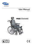
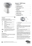
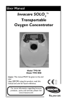
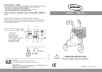
Invacare® I-Transia™
EN Adjustable Freestanding Rail System
User Manual
IENI
1 General
The freestanding rail system is a portable rail system which can be set
up in many locations* and requires no mounting on walls, ceiling or
floors. The freestanding rail system is length and height adjustable.
*The freestanding rail system and hoist are not designed for
use in moist or wet areas.
1.1 Symbols
Signal words are used in this manual and apply to hazards or unsafe
practices which could result in personal injury or property damage.
See the information below for definitions of the signal words.
WARNING!
– Warning indicates a potentially hazardous situation
which, if not avoided, could result in death or serious
injury.
CAUTION!
– Caution indicates a potentially hazardous situation
which, if not avoided, may result in property damage
or minor injury or both.
1.3 Conditions for Use
The use of the I-Transia hoist is subject to the following:
•
•
•
•
•
•
IMPORTANT
– Indicates a hazardous situation that could result in
damage to property if it is not avoided.
Gives useful tips, recommendations and information for
efficient, trouble-free use.
This product complies with Directive 93/42/EEC
concerning medical devices.
•
•
The I-Transia should only be used by trained personnel.
The safe working load (SWL), 205 kg (450 lbs) or 250 kg (550
lbs), must not be exceeded. Refer to 2.3 Load Limits, page 2 .
The instruction offered by Invacare to all customer groups in
connection with the purchase of a hoist has been received.
The caregiver pays attention to the well-being of the user when
using the hoist.
The hoist is used in rail systems which are installed, tested and
approved according to DS/EN 10535 and Invacare’s stipulations.
Only technicians who have been certified by Invacare may install
and test the rail systems.
The hoist is used with an Invacare hanger bar.
The hoist is used with an Invacare lifting sling or with other
suitable slings. Refer to the I-Transia hoist user manual for more
information about slings. .
1.4 Service Life
The I-Transia freestanding rail system has an expected lifetime of 15
years, if used according to the procedures in this manual.
The launch date of this product is stated in the EC
declaration of conformity.
1.2 Intended Use
I-Transia is a hoist which covers the need for lifting or moving a
person with disabilities in the home care sector, nursing homes,
rehabilitation centres, and institutions.
This manual MUST be given to the user of the product.
BEFORE using this product, read this manual and save for future reference.
I-Transia™
Pinch Points and Positioning
2 Safety
2.1 General Guidelines
WARNING!
– Read and understand these instructions. DO NOT
use this product without reading and understanding
these instructions and the hoist user manual. If you
need help with these instructions, contact a healthcare
professional or an Invacare dealer. Otherwise injury or
damage may occur.
ACCESSORIES WARNING
– Invacare products can only be used with accessories
made by Invacare. Accessories not made by Invacare
have not been tested by Invacare. Accessories not
made by Invacare should not be used.
The information contained in this document is subject to
change without notice.
Check all parts for shipping damage before using. In case of damage,
DO NOT use the equipment. Contact an Invacare dealer for further
instructions.
WARNING!
Risk of Injury
Pinch points are present on the strap carabiner A and
fingers could be pinched.
The hanger bar B can move suddenly and cause injury.
– ALWAYS keep hands and fingers clear of moving parts
to avoid injury.
– When positioning the hoist, be aware of the position of
the hanger bar B and the patient. Injury could occur.
2.2 Operating Information
This section of the manual contains general safety information about
your product. For specific safety information, refer to the appropriate
section of the manual and procedures within that section.
General
WARNING!
This manual covers the installation of the freestanding
rail system. Refer to the I-Transia user manual for safety
information related to using and maintaining the hoist.
– Read the instructions carefully before using the
I-Transia and in connection with cleaning and service
of the hoist.
– The freestanding system can be set up and taken down
by one person.
– The freestanding rail system should be set up on a level
surface.
– The I-Transia’s maximum load must never be exceeded.
– The I-Transia may only be used to lift or move a person
with disabilities.
– The freestanding rail system must not be used for any
other purpose than that stated in this user manual. The
rail system is not a playground or a swing device.
– If the I-Transia fails while in use, stop using the hoist,
transfer the patient using a different method and
contact an Invacare dealer for repair by a certified
technician.
– This product is mechanically protected against derailing
and jamming.
– The end stops have to be properly installed and locked
with spring pins, and the 2 yellow thumb screws on
the top brackets have to be properly tightened before
using the system.
– Check the freestanding system regularly to ensure it
is stable.
WARNING!
Pinch points are present in the pivot points of the vertical
poles and between the top rail and the vertical poles.
– ALWAYS keep hands and fingers clear of moving parts
to avoid injury.
– ALWAYS keep hands and fingers clear of pinch points
during setup of the freestanding rail system.
2.3 Load Limits
Read the label on each component which indicates the maximum load
limits for each component.
The component, e.g. hanger bar, lifting sling, etc. labelled with the
lowest load limit determines the maximum load limit for the entire
system.
This maximum load limit must not be exceeded.
Please note that the max load may change when different components
are used, such as hanger bars, lifting slings, etc.
2
1183379A
2.4 Product Labeling
3.2 Inspection
WARNING!
Risk of Injury
Damaged components of the freestanding rail system
could cause injury.
– Inspect the packaging upon receipt.
– If the packaging is damaged, the components of the
freestanding rail system should be carefully checked for
noticeable imperfections, defects or flaws.
– If damage is suspected, DO NOT use or assemble the
freestanding rail system. Contact an Invacare dealer.
3.3 Assembling the Freestanding Rail
Item
Label Text
1
WARNING
Tighten top wing knob nuts firmly by hand
before system usage.
For ease of assembly, ensure vertical posts are in their lowest
position. Refer to 3.6 Adjusting the Height, page 5 .
1.
Open the legs A of one vertical pole module B.
2.
3.
Raise the vertical pole module B.
Lift one end of the top bracket and rail module \C and mount it
on top of the vertical pole module B.
2
3
3 Setup
3.1 Included Items
The top bracket must be flush with the mark \G on the
vertical pole.
It will be necessary to tilt the top bracket and rail module
and vertical pole to assemble them.
Each kit contains the following items:
1.
2.
3.
4.
5.
6.
Top bracket and rail module
Vertical pole module (x2)
User manual, part number 1183379 (not shown)
Hoist*
Hanger bar
5 mm Allen key (not shown)
* The Hoist comes with a separate Hoist User Manual (part
number 1183377). Refer to this manual for information on
the safe operation and maintenance of the hoist.
4.
1183379A
Lock the top bracket C to the vertical pole B with the locking
arm D.
3
I-Transia™
3.4 Installing the Hoist
5.
6.
7.
Open the legs of the second vertical pole module.
Raise the second vertical pole module B.
Lift the other end of the top bracket and rail module C and
mount it on top of the vertical pole module C.
WARNING!
– Before installing the hoist, read and understand the
hoist user manual, part number 1183377.
1.
Loosen the two screws H securing the end stop I to the rail E.
2.
Remove the end stop from the rail.
The top bracket must be flush with the mark on the
vertical pole G.
8.
It may be necessary to tilt the end stop as you remove
it from the rail.
Lock the top bracket C to the vertical pole B with the locking
arm D.
If the end stop cannot be tilted and removed, remove the
two screws from the end stop.
3.
Insert the hoist J into the rail E.
4.
Mount the end stop I, making sure that the spring pin K is
positioned in the pre-drilled hole L.
The end stop may need to be tilted to enable mounting.
9.
4
Lock the rail module E to the top bracket module C with the
two yellow thumb screws F.
If the screws were removed while removing the end stop,
install the two screws after the end stop is in position.
1183379A
3.6 Adjusting the Height
Follow this procedure to adjust the height of the rail.
1.
2.
5.
Locate the height adjustment socket M at the side of the vertical
pole B.
Insert the provided 5 mm Allen key N in the height adjustment
socket at the side of the vertical pole.
Tighten the two screws H in the end stop I.
3.
4.
5.
Turn the Allen key to adjust the height of the freestanding rail
system.
Repeat STEPS 1–3 for the opposite vertical pole.
Make sure the top bracket and rail are level.
Use a spirit level to ensure the top bracket and rail are
level.
3.5 Adjusting the Width
Follow this procedure to adjust the freestanding rail system to the
room size.
3.7 Installing the Charging Dock
1.
Loosen the two yellow thumb screws F on the top the bracket
C.
1.
2.
3.
Push or pull the top bracket C to adjust the width of the system.
Tighten the thumb screws F to secure the top bracket C to
the rail E.
4 After Use
Use the enclosed hook and loop fastening strips (not shown)
to secure the recharging dock A to the lower portion of the
vertical pole B.
4.1 Disassembly
1.
2.
Lower the vertical poles to the lowest position. 3.6 Adjusting
the Height, page 5 .
Performing one of the following:
•
•
4.
Reverse the hoist installation steps to remove the hoist.
Refer to 3.4 Installing the Hoist, page 4 .
Loosen the screws H in the end stops I and move the
end stops on either side of the hoist to secure the hoist in
position.
Repeat STEPS 1–3 for the other side of the freestanding rail
system.
1183379A
5
I-Transia™
6 Troubleshooting
6.1 Troubleshooting Table
3.
4.
PROBLEM
SOLUTION
PROCEDURE
The system is not
stable.
Check that the
feet are mounted
correctly.
Refer to 3.3
Assembling the
Freestanding Rail,
page 3 .
Check the vertical
poles are pushed
securely into the top
bracket.
Lower the vertical poles to the lowest position. Refer to 3.6
Adjusting the Height, page 5 .
Reverse the assembly steps to disassemble the system. Refer to
3.3 Assembling the Freestanding Rail, page 3 .
Check that the rails
are level.
It may be necessary to push the top bracket upwards in
order to separate it from the vertical pole module.
Check that the
top brackets are
tightened.
4.2 Transport
1.
2.
Check that the top
brackets have been
positioned correctly.
Disassemble the freestanding rail system. Refer to 4.1
Disassembly, page 5 .
Put the components of the system into the portable carrier bag
(optional accessory).
Check that the
yellow thumb
screws are
tightened.
4.3 Storage
CAUTION!
Risk of Product Damage
– The freestanding rail system should be stored in a room
where the humidity does not exceed 70%.
– Do not store the system in a bathroom.
5 Maintenance
Check the top brackets for defects or
deformities. If found, contact an Invacare
dealer or certified technician.
The height
adjustment is not
working.
5.1 Cleaning
To prevent cross-infection, the parts of the hoist that come in contact
with caregivers and patients must be cleaned and disinfected. A soft
cloth, dampened with water and a small amount of dish liquid, is all
that is needed to clean the hoist, lifting strap and carabiner. The hoist
can be cleaned with non-abrasive cleaners.
Refer to 3.6
Adjusting the Height,
page 5 .
If the top part of the vertical pole is not
moving when turning the Allen key, stop
using the system and contact an Invacare
dealer or certified technician.
CAUTION!
Risk of Product Damage
– DO NOT autoclave or use harsh chemicals when
cleaning the system.
Clean the freestanding system with a damp cloth using ordinary
household detergents and household disinfectant.
Using the 5 mm
Allen key, check that
the vertical pole is
not stuck in the far
end position.
7 Technical Data
7.1 Typical Product Parameters
Freestanding rail system
Minimum Dimensions
2020 x 2720 mm (79.5 in x 107 in)
(HxW)
Maximum Dimensions
2820 x 3890 mm (111 in x 153 in)
(HxW)
Maximum lifting
250 kg (550 lb)
capacity
Total weight without hoist
Freestanding rail
52.0 kg (114.5 lb)
system
Vertical pole, each
13.5 kg (30 lb)
Top brackets and rail 25.0 kg (55 lb)
Materials
Rails and posts
Feet
Brackets
6
Anodized aluminum
Powder varnished steel
Powder varnished steel
1183379A
8 Warranty
THIS WARRANTY SHALL BE EXTENDED TO COMPLY WITH STATE
OR PROVINCIAL LAWS AND REQUIREMENTS.
8.1 Limited Warranty — Europe
Terms and conditions of the warranty are part of the general terms
and conditions particular to the individual countries in which this
product is sold.
In order to comply with Health & Safety regulations and to ensure
that our employees are not exposed to the risk of infection, we must
insist that all products returned for repair are thoroughly cleaned.
Any product sent to Invacare which appears to be contaminated will
be rejected and disposed of immediately at the customer’s expense.
8.2 Limited Warranty — North America
PLEASE NOTE: THE WARRANTY BELOW HAS
BEEN DRAFTED TO COMPLY WITH FEDERAL LAW
APPLICABLE TO PRODUCTS MANUFACTURED AFTER
JULY 4, 1975.
This warranty is extended only to the original purchaser/user of our
products.
This warranty gives you specific legal rights and you may also have other
legal rights which vary from state to state.
Invacare warrants the products manufactured to be free from defects in
materials and workmanship for a period of one year from the date of
purchase. If within such warranty period any such product shall be proven
to be defective, such product shall be repaired or replaced, at Invacare’s
option. This warranty does not include any labor or shipping charges
incurred in replacement part installation or repair of any such product.
Invacare’s sole obligation and your exclusive remedy under this warranty
shall be limited to such repair and/or replacement.
For warranty service, please contact the dealer from whom you purchased
your Invacare product. In the event you do not receive satisfactory
warranty service, please write directly to Invacare at the address on the
back cover, provide dealer’s name, address, date of purchase, indicate
nature of the defect.
Invacare Corporation will issue a serialized return authorization. The
defective unit or parts MUST be returned for warranty inspection using
the serial number, when applicable as identification within 30 days of
return authorization date. Do not return products to our factory without
our prior consent. C.O.D. shipments will be refused; please prepay
shipping charges.
LIMITATIONS AND EXCLUSIONS: THE FOREGOING WARRANTY
SHALL NOT APPLY TO SERIAL NUMBERED PRODUCTS IF THE
SERIAL NUMBER HAS BEEN REMOVED OR DEFACED, PRODUCTS
SUBJECTED TO NEGLIGENCE, ACCIDENT, IMPROPER OPERATION,
MAINTENANCE OR STORAGE, PRODUCTS MODIFIED WITHOUT
INVACARE’S EXPRESS WRITTEN CONSENT (INCLUDING, BUT
NOT LIMITED TO, MODIFICATION THROUGH THE USE OF
UNAUTHORIZED PARTS OR ATTACHMENTS; PRODUCTS
DAMAGED BY REASON OF REPAIRS MADE TO ANY COMPONENT
WITHOUT THE SPECIFIC CONSENT OF INVACARE, OR TO
A PRODUCT DAMAGED BY CIRCUMSTANCES BEYOND
INVACARE’S CONTROL, AND SUCH EVALUATION WILL BE SOLELY
DETERMINED BY INVACARE. THE WARRANTY SHALL NOT APPLY
TO PROBLEMS ARISING FROM NORMAL WEAR OR FAILURE TO
ADHERE TO THE INSTRUCTIONS IN THIS MANUAL.
THE FOREGOING WARRANTY IS EXCLUSIVE AND IN LIEU OF ANY
OTHER EXPRESS WARRANTIES. IMPLIED WARRANTIES, IF ANY,
INCLUDING THE IMPLIED WARRANTIES OF MERCHANTABILITY
AND FITNESS FOR A PARTICULAR PURPOSE, SHALL NOT EXTEND
BEYOND THE DURATION OF THE EXPRESSED WARRANTY
PROVIDED HEREIN AND THE REMEDY FOR VIOLATIONS OF
ANY IMPLIED WARRANTY SHALL BE LIMITED TO REPAIR OR
REPLACEMENT OF THE DEFECTIVE PRODUCT PURSUANT TO THE
TERMS CONTAINED HEREIN. INVACARE SHALL NOT BE LIABLE FOR
ANY CONSEQUENTIAL OR INCIDENTAL DAMAGES WHATSOEVER.
SOME STATES DO NOT ALLOW EXCLUSION OR LIMITATION OF
INCIDENTAL OR CONSEQUENTIAL DAMAGE, OR LIMITATION
ON HOW LONG AN IMPLIED WARRANTY LASTS, SO THE ABOVE
EXCLUSIONS AND LIMITATIONS MAY NOT APPLY TO YOU.
1183379A
7
United Kingdom
Invacare Limited • Pencoed Technology Park, Pencoed, Bridgend CF35 5AQ • Tel: (44) (0) 1656
776 222 • Fax: (44) (0) 1656 776 220 • www.invacare.co.uk • [email protected]
Ireland
Invacare Ireland Ltd • Unit 5 Seatown Business Campus • Seatown Road • Swords • County Dublin –
Ireland • Tel : (353) 1 810 7084 • Fax: (353) 1 810 7085 • www.invacare.ie • [email protected]
Australia
Invacare Australia Pty Ltd. • 1 Lenton Place • North Rocks • NSW 2151 • Australia • Tel: (61) 2
8839 5333 • Fax: (61) 2 8839 5353 • www.invacare.com.au • [email protected]
New Zealand
Invacare New Zealand • 4 Westfield Place • Mt. Wellington • Auckland • New Zealand • Tel: (64) 9
917 3939 • Fax: (64) 9 917 3957 • www.invacare.co.nz • [email protected]
France
Invacare Poirier SAS • Route de St Roch • F-37230 Fondettes • Tel: (33) (0)2 47 62 64 66 • Fax:
(33) (0)2 47 42 12 24 • www.invacare.fr • [email protected]
Switzerland
Invacare AG • Benkenstrasse 260 • CH-4108 Witterswil • Tel.: (41) (0)61 487 70 80 • Fax.: (41)
(0)61 487 70 81 • www.invacare.ch • [email protected]
Deutschland
Invacare GmbH • Alemannenstraße 10 • D-88316 Isny • Tel: (49) (0)75 62 7 00 0 • Fax: (49) (0)75
62 7 00 66 • www.invacare.de • [email protected]
Portugal
Invacare Lda • Rua Estrada Velha • 949 • P-4465-784 Leça do Balio • Tel: (351) (0)225 1059 46/47 •
Fax: (351) (0)225 1057 39 • www.invacare.pt • [email protected]
España
Invacare SA • c/Areny s/n • Polígon Industrial de Celrà • E-17460 Celrà (Girona)Tel: (34) (0)972 49
32 00 • Fax: (34) (0)972 49 32 20 • www.invacare.es • [email protected]
Belgium & Luxemburg
Invacare nv • Autobaan 22 • B-8210 Loppem • Tel: (32) (0)50 83 10 10 • Fax: (32) (0)50 83 10 11
• [email protected] • www.invacare.be
Nederland
Invacare BV • Celsiusstraat 46 • NL-6716 BZ Ede • Tel: (31) (0)318 695 757 • Fax: (31) (0)318 695
758 • [email protected] • www.invacare.nl • [email protected]
Norge
Invacare AS • Grensesvingen 9 • Postboks 6230 • Etterstad • N-0603 Oslo • Tel: (47) (0)22 57 95
00 • Fax: (47) (0)22 57 95 01 • [email protected] • www.invacare.no • [email protected]
Österreich
Invacare Austria GmbH • Herzog Odilostrasse 101 • A-5310 Mondsee • Tel: (43) 6232 5535 0 •
Fax: (43) 6232 5535 4 • [email protected] • www.invacare.at
Manufacturer
V. Guldmann A/S
Graham Bells Vej 21–23A
DK-8200 Aarhus N, Denmark
EU Representative
Invacare Limited
Pencoed Technology Park
Pencoed, Bridgend CF35 5AQ
United Kingdom
Invacare Corporation
USA
One Invacare Way
Elyria, Ohio USA
44036–2125
800–333–6900
www.invacare.com
1183379-A
2013-04-29
*1183379A*
Making Life’s Experiences Possible™