1
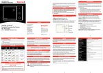
BW TECHNOLOGIES BY HONEYWELL || WWW.HONEYWELLANALYTICS..COM INTELLIDOX DOCKING MODULE QUICK REFERENCE GUIDE Quick Reference Guide 50104991-166 || QRG-EN-FMSU_B1 English ©2015 BW Technologies. All rights reserved. www.honeywellanalytics.com/support/product-registration Warranty Registration www.honeywellanalytics.com Situations which, if not avoided, may result in property damage. Hazardous situation which, if not avoided, may result in moderate or minor injury. Hazardous situation which, if not avoided, could result in death or serious injury. Hazardous situation which, if not avoided, will result in death or serious injury. This symbol identifies the most extreme hazardous situations. Web 1-800-663-4164 1-888-749-8878 +44(0)1295 700300 +1-403-248-9226 Wear yellow. Work safe. Telephone Contact BW Technologies by Honeywell This manual uses the following signal words, as defined by ANSI Z535.4-1998: This equipment uses potentially harmful gas for calibrations. The module must be attached to a venting system or be used in a well-ventilated area. Signal Words Brand or product names are trademarks of their respective owners. Fleet Manager II and IntelliDoX are trademarks of BW Technologies and/or Honeywell: Indoor use only; • Normal atmosphere (20.9% v/v O2) that is free of hazardous gas; • Temperature range of +50F to +95F (+10C to +35C) ; and • Relative humidity of 10% to 90% non-condensing. If the intended operating environment does not match these criteria, BW Technologies recommends that you consult a qualified professional specialist prior to installing and using any modules. Trademarks Ensure that you are familiar with the use of personal gas detection devices and accessories, and take appropriate action in the event of an alarm condition. The module is designed to be safe in the following conditions: Normal Operating Conditions Docking Module Modules may be connected to a network via an Ethernet cable for enhanced access to and control of administrative and maintenance tasks. Modules are compatible with Fleet Manager II software, version 4.0 or higher. Modules may be used as individual, stand-alone docking stations. They may also be connected to form gangs of up to 5 modules that function independently. Connected modules share power, network and gas connections. The module is an automatic test and calibration station for use with portable gas detectors manufactured by BW Technologies. The module automatically performs essential procedures including sensor identification, bump tests, calibrations, alarm tests and data transfers. It also retains a cumulative record of detector datalogs and event logs that are transferred to and stored in onboard memory. 2840 2 Ave. SE Calgary, Alberta Canada T2A 7X9 While this information is presented in good faith and believed to be accurate, BW Technologies disclaims the implied warranties of merchantability and fitness for a particular purpose and makes no express warranties except as may be stated in its written agreement with and for its customers. In no event is BW Technologies liable to anyone for any indirect, special or consequential damages. The information and specifications in this document are subject to change without notice. The module is designed to support multiple detectors manufactured by BW Technologies. As a result, certain procedures, features and options described in this manual may not be supported by all of the compatible detector models. To understand which procedures, features and options are supported, refer to the appropriate detector operator manual. Canada: 1-800-663-4164 USA: 1-888-749-8878 Europe: +44 (0) 1295 700300 Other regions: 1-403-248-9226 Fax: 1-403-273-3708 Web: www.honeywellanalytics.com This publication is a quick-start reference guide for the IntelliDoX Docking Module (the module) manufactured by BW Technologies by Honeywell (BW Technologies). It includes general information and basic instructions for assembling and preparing the module for use. For detailed information and instructions, refer to the module operator manual. About the IntelliDoX Docking Module About this Publication Important Safety Information: Read First Each IntelliDoX Docking Module package contains: 1. To ensure personal safety, read all Safety Information and Warnings before using this equipment. 2. Use this equipment only as specified by the manufacturer. Failure to do so may impair protection provided by the equipment. 3. The safety and security of any system or network incorporating this equipment and its accessory components is the responsibility of the assembler of the system. 4. Follow all required National Electric Codes (NEC) and safety standards. 5. This IntelliDoX module is intended for use as a stand-alone docking module, or as a component in a connected gang of up to five IntelliDoX modules. 1. One module with a factory-installed nest for a compatible portable gas detector; 2. One printed Quick Reference Guide; 3. One CD containing the module Operator Manual and Quick Reference Guide in PDF format; and 4. One CD containing Fleet Manager II software, version 4.0 or higher. If module parts are damaged or missing, contact BW Technologies or an authorized distributor immediately. IntelliDoX Enabler Kit One Enabler Kit is required for each individual module or gang of up to 5 connected modules. Each Enabler Kit contains: 1. 2. 3. 4. 5. 6. 7. One power supply and AC power cord appropriate to shipping destination; One IntelliDoX end plate; One ethernet cable; Gas tubing, 1/8 inch I.D., 4.6 meters (15 feet); Quick connect fittings; Inlet filters and plugs; Connectors with attached 3/16 inch I.D. tubing for use with demand flow regulators; 8. Miscellaneous connectors; 9. One CD containing the IntelliDoX Operator Manual and Quick Reference Guide in PDF format; and 10. One CD containing Fleet Manager II software, version 4.0 or higher. If Enabler Kit parts are damaged or missing, or if additional Enabler Kits are required, contact BW Technologies or an authorized distributor immediately. Fleet Manager II Software Fleet Manager II is proprietary instrument management software developed by BW Technologies. You can use Fleet Manager II to configure and manage compatible devices, automate procedures, and import and manage data and event logs from detectors and modules. For more information, refer to the Fleet Manager II operator manual or visit the product website at www.honeywellanalytics.com. 1. If the equipment is damaged or parts are missing, contact BW Technologies immediately. 2. Substitution of components may impair the safety of the equipment. 3. Do not attempt to disassemble, adjust, or service the equipment unless instructions are provided to perform a procedure, or a component is listed as a user-replaceable component in the user manual. Use only BW Technologies replacement components. 4. To eliminate the risk of electrical shock, disconnect the equipment when cleaning or performing maintenance. 5. This equipment uses potentially harmful gas for calibrations. The equipment must be attached to a venting system or be used in a well-ventilated area. 6. To prevent gas leaks, the end plate must be attached and locked with the latch arm before connecting power supply and/or connecting gas cylinders. The end plate must remain securely latched at all times during operation. 7. Perform calibrations and bump tests only in a normal atmosphere (20.9% v/v O2) that is free of hazardous gas. 8. The maximum recommended calibration tubing length is 10 meters (33 feet). Use of tubing that is longer than the recommended length may result in inaccurate or failed compliance tests or calibrations. 9. The maximum recommended exhaust tubing length is 15 meters (49.5 feet). 10. Ensure that the inlet filter is clean. EC Declaration of Conformity 11. The use of calibration gas cylinders other than those specified by BW Technologies may result in unsafe calibration or possible non-recoverable failure of the equipment, and will invalidate the warranty. 12. Do not use calibration gas cylinders past their expiration date. 13. Ensure that all calibration gas cylinders are in good condition. 14. Ensure that all calibration gas cylinders contain enough gas. 15. Ensure the exhaust line is not connected to a negative pressure system. 16. A demand flow regulator must be used with all calibration gas cylinder connections. The module inlet should not be pressurized. 17. Failed tests can result if inlets are not set up correctly. 18. Do not expose the equipment to electrical shock or severe and/or continuous mechanical shock. 19. Do not immerse the equipment in liquids. • • Products may contain materials that are regulated for transportation under domestic and international dangerous goods regulations. Return product in compliance with appropriate dangerous goods regulations. Contact freight carrier for further instructions. To prevent the corruption or loss of data and/or software and/or firmware, do not deactivate the equipment while performing datalog transfers, bump tests, calibrations or other operations. To download a PDF of this Declaration, visit the product website at www.honeywellanalytics.com EC Declaration of Conformity In accordance with EN ISO / IEC 17050-1:2010 IntelliDoX Declaration Number: Description: Intended Use: 2004Y0065_01 Docking Module and Automatic Calibration Station for use with BW portable gas detectors Sensor identification, bump tests, calibrations, alarm tests and data transfers Manufacturer: BW Technologies 2840 2nd Ave SE Calgary, Alberta T2A 7X9 Canada Trading Company: Life Safety Distribution AG Javastrasse 2 8604 Hegnau Switzerland We hereby declare that the product identified above meets the requirements of the following EC Directives and therefore qualifies for free movement within markets comprising the European Union (EU) and the European Economic Area (EEA). EMC Directive (EMC) 2004/108/EC Conforms to: EN 61326-1:2013 Electrical equipment for measurement control and laboratory use – EMC requirements Low Voltage Directive (LVD) 2006/95/EC Conforms to: EN 61010-1:2010 Year of CE Marking: Name: Safety requirements for electrical equipment for measurement, control and laboratory use – Part 1: General requirements 2013 Digitally signed by [email protected] DN: [email protected] Date: 2015.01.16 11:56:00 -05'00' Signature: Steve Uliasz, Regulatory Compliance Engineer For and on behalf of: BW TECHNOLOGIES BY HONEYWELL WWW.HONEYWELLANALYTICS.COM Toll-free, Canada: Toll-free, USA: Toll-free, Europe: All other regions: What’s in the Box Date: 16-JAN-2015 BW Technologies. 2840 2nd Ave SE, Calgary, Alberta T2A 7X9 Canada 50104991-166 || QRG-EN-FMSU_B1 INTELLIDOX DOCKING MODULE QUICK REFERENCE GUIDE At a Glance Prepare a Module for Use IntelliDoX, top IntelliDoX, bottom Hinge Panel latch Latch arm Detachable back panel Lid Compatible detector Lid latch USB port LCD screen Keypad Latch lock Inlet key Left side Inlet key 1. Select a suitable installation location. 2. Attach the end plate. For more information, see Attach the End Plate. 3. Connect an inlet filter to the purge inlet. 4. Insert an inlet plug into each unused inlet. 5. Connect the exhaust tubing. 6. Connect the power. 7. Connect to a network. 8. Connect the calibration gas cylinder or cylinders. 9. Configure the gas inlets. Attach the End Plate Right side, with end plate Top DIN rail mount Lid Network connection Lid Power connection End plate Latch arm Exhaust outlet Bottom DIN rail mount Purge inlet Gas inlet 1 Gas inlet 2 Gas inlet 3 Gas inlet 4 Inlet key Inlet key The end plate must be attached and locked with the latch arm before connecting power supply or connecting gas cylinders. The end plate must remain securely latched at all times during operation. If the end plate is detached during operation, disconnect power and replace the end plate immediately. Abnormal performance may occur when the end plate is detached or removed. Failure to comply may result in incorrect or failed compliance tests or calibrations. 1. Unlock and raise the latch arm. 2. Attach the end plate. Verify that the end plate is firmly attached and set flush with the edge of the module. 3. Lower and lock the latch arm. Connect Power Keypad Buttons Button Screen Color Action Color Status Scroll right Gray Idle Blue Prompt for user action Yellow Activity in progress Green Activity successful Red Warning, or activity failed Scroll left Scroll up Scroll down Press and hold to display the module settings menu. Press to select a menu item or save changes. Press and hold to cancel an operation. Press to return to the previous screen or cancel changes. 1. Verify that the power supply and power cord provided are compatible with the local power source. Connect the AC power cord to the power supply. 2. Connect the power supply to the module. Press firmly until you hear a click. The click confirms that the plug is locked. 3. Plug the AC power cord into a suitable wall outlet. 4. When the power is connected, the LCD activates and a self-test is performed. Disconnecting the Power To deactivate a module or gang of modules, disconnect the power supply. The module or gang of modules deactivates immediately and without warning. 1. Retract the plastic cover on the plug to unlock it. 2. While the cover is retracted, pull the plug out of the module. BW TECHNOLOGIES BY HONEYWELL WWW.HONEYWELLANALYTICS.COM Connect a Module to a Network Individual modules and gangs of up to 5 connected modules may be connected to a computer network via an Ethernet cable. Gangs of up to 5 modules share one network connection. Each individual or connected module requires a unique and separate IP address. To connect the module to a network, insert one end of the Ethernet cable into the Ethernet port on the module. Insert the free end of the Ethernet cable into the network outlet. When the module is connected to the network, the network symbol is displayed at the top right corner of the LCD. For more information, refer to the module and/or Fleet Manager II operator manuals. Connect Modules Up to 5 modules may be connected to form a gang. Connected modules share a power supply, network connection, exhaust tubing, inlet filter assemblies, and connected calibration gas cylinders. 1. Unlock and raise the latch arm on the first module. If an end plate is attached, remove it. 2. Align the connection port and outlets on the first module with the connection port and inlets on the second module. 3. Push the modules firmly together to connect. Verify that the stands are connected, and then lower and lock the latch arm on the first module. 4. Repeat as necessary to connect up to a maximum of five modules in one gang. 5. Attach the end plate to the last module in the gang. Verify that the latch arm is lowered and locked. 6. Verify that connected modules are firmly attached and latch arms are lowered and locked. 7. Connect the inlet filters, tubing, network connection and power cord. For more information, see Prepare a Module for Use. 8. Verify that each module in the gang is activated and a consecutive bay number is displayed on the LCD. Connect a Calibration Gas Cylinder The IntelliDoX Enabler Kit includes tubing and quick connect fittings that are appropriate for use with calibration gas cylinders that are approved for use with this product. For best results, BW Technologies recommends that the tubing is between 39 inches (1 meter) and 33 feet (10 meters) in length for calibration gas cylinders. 1. Connect a demand flow regulator to the calibration gas cylinder 2. Use the supplied fittings and tubing to connect the calibration gas cylinder to the inlet. 3. Configure the gas inlets before using the module. See Configure Gas Inlets. Configure Gas Inlets Bump Test FastBump 1. Press and hold on the keypad until Adjust dock station settings is displayed on the LCD. 2. Press or to select Configure gas inlets and then press . A bump test is a procedure that confirms a detector’s ability to respond to target gases by exposing the detector to a known gas concentration. If AutoBump on Insertion is configured, then the bump test starts automatically when the detector is recognized. If AutoCal on Overdue Sensors is enabled and if a calibration is also due, then no bump test is performed. Instead, calibration starts automatically when the detector is recognized. FastBump is an accelerated compliance test that confirms a detector’s ability to respond to target gases by exposing the detector to a known gas concentration. When a compatible detector is inserted into the configured module, FastBump and event log transfers begin automatically after the detector is recognized. Other procedures specified to occur automatically on insertion are suppressed. 3. The Inlet 1 overview is displayed. If a multi-inlet key is inserted in an individual module, or one or more connected modules, then four inlet tabs are displayed. 4. Press or to select an inlet, and then press to display the Inlet edit menu. Gas blend is highlighted. 5. Select a gas blend, and then configure the gas concentration. For multi-gas blends, configure the concentration for each gas in the blend. 6. Record the lot number of the calibration gas cylinder. 7. Repeat steps 3, 4, 5, and 6 until all of the gas inlets are configured. 8. Press to close the Inlet edit menu and return to the Inlet overview. Press again to return to Adjust dock station settings. For more information, refer to the module operator manual. 1. Insert a compatible detector. After the detector is recognized, the detector operations menu is displayed. 2. Press or to select Bump test my detector and then press to continue. 3. The LCD changes to yellow and the bump test begins. Progress screens are displayed while the test procedures are performed. Testing alarms Testing sensors Insert a Detector Activate the detector and verify that it is in normal operating mode before performing bump test or calibrations. Activation is not required for charging a battery or configuring a detector prior to activation. For more information, refer to the appropriate detector operator manual. 1. Verify that the detector is compatible with the module. 2. Open the lid. Insert the detector and then close the lid. Detector identification is displayed. 3. After the detector is recognized, procedures specified to occur automatically on insertion are performed. If the detector contains a rechargeable battery, battery charging begins. Progress screens may be displayed while certain procedures are performed. 4. After the detector is recognized and automated procedures are completed, the detector operations menu is displayed. 5. Press or to select a menu item and then follow the on-screen instructions to perform the selected procedure. Charge a Detector Insert a detector. After the detector is recognized, procedures specified to occur automatically on insertion are performed. If the detector contains a rechargeable battery, battery charging begins. After the procedures are completed, you can leave the detector in the module for charging. If the detector is activated, the module will deactivate it after 10 minutes of inactivity and continue charging. 4. When the bump test is successful, the LCD changes to green and Bump test passed is displayed. If the module is configured to automatically download datalogs, then the detector datalogs are transferred to the module after the test is complete. Bump Testing test sensors passed 5. Press to return to the detector operations menu. 6. If the bump test fails, the LCD changes to red and the Bump test failed message is displayed. indicates failed alarm and/or sensor test. Bump test failed 7. If the module is configured to automatically calibrate the detector when a bump test fails, then the calibration procedure begins. To understand how to respond appropriately to failed tests, refer to the detector operator manual. FastBump can only be performed with a compatible detector via a module that is configured for FastBump. To determine if a FastBump is available, refer to the appropriate detector operator manual. Calibration Calibration is a two-step procedure that determines the measurement scale for the detector’s response to gas. In the first step, a baseline reading is taken in a clean, uncontaminated environment. In the second step, the sensors are exposed to known concentrations of gas. The detector uses the baseline and known gas concentrations to determine the measurement scale. If AutoCal on Overdue Sensors is enabled and if a calibration is also due, then calibration starts automatically when the detector is recognized. 1. Insert a compatible detector. After the detector is recognized, the detector operations menu is displayed. 2. Press or to select Calibrate my detector and then press to continue. 3. The LCD changes to yellow and the calibration begins. Progress screens are displayed while the test procedures are performed. 4. When the calibration is successful, the LCD changes to green and Calibration passed is displayed. If the module is configured to automatically download datalogs, then the detector datalogs are transferred to the module after the test is complete. Calibration passed 5. Press to return to the detector operations menu. 6. If the calibration fails, the LCD changes to red and Calibration failed is displayed. indicates failed alarm and/or sensor test. Clean and Maintain the Module Disconnect power before performing maintenance or cleaning. To avoid personal injury or damage to the module, use only replacement parts and/or accessories obtained from BW Technologies or an authorized distributor. Substitution of components may impair the safety of the equipment. Basic maintenance To maintain the module in good operating condition, perform the following basic maintenance as required: 1. Maintain a log of all maintenance that is performed. 2. Clean the exterior with a soft, damp cloth. • Do not immerse in liquids. • Do not use solvents, soaps or polishes. 3. Confirm that the inlet filter is free of dirt. Replace if required. Once service is complete, reconnect the power supply. When power is connected, the LCD activates and selftest is performed. Replacement Parts and Accessories Replaceable parts are sold separately. To receive a complete list of the replaceable parts approved for use with this product, contact BW Technologies or an authorized distributor, or visit the product website at www.honeywellanalytics.com Gas detectors, calibration and purge gas cylinders, and other accessories are sold separately. To receive a complete list of calibration gases and accessories approved for use with this product, contact BW Technologies or an authorized distributor, or visit the product website at www.honeywellanalytics.com. Calibration Equipment and Gases • The use of calibration gas cylinders other than those specified by BW Technologies may result in unsafe calibration or possible non-recoverable failure of the equipment, and will invalidate the warranty. • A demand flow regulator must be used with all calibration gas cylinder connections. The module inlet should not be pressurized. To receive a complete list of calibration gases and accessories approved for use with this product, contact BW Technologies or an authorized distributor, or visit the product website at www.honeywellanalytics.com. Calibration failed 7. To understand how to respond appropriately to failed tests, refer to the appropriate detector operator manual. 50104991-166 || QRG-EN-FMSU_B1 INTELLIDOX DOCKING MODULE QUICK REFERENCE GUIDE