1
Drive Identification / Display Menu
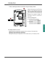
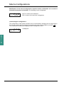
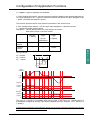
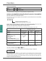
Drive identification
This parameter can always be displayed. It indicates the speed controller power and voltage as
indicated on the identification label.
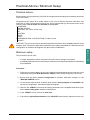
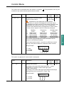
rEF
0.37 kW 200/240 V
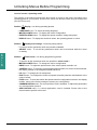
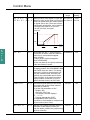
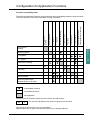
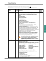
Display menu (selection of parameters displayed during operation)
The following parameters can be accessed whatever position the access switch is in, in stop or
run mode.
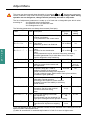
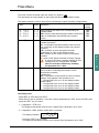
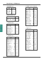
Label
Var. State
Code Function
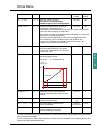
--rdY
rUn
ACC
dEC
CLI
dCb
nSt
Obr
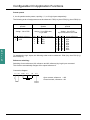
State of the speed controller : indicates a fault or
the motor operating phase :
rdY = speed controller ready,
rUn = motor in steady state or run command present and zero
reference,
ACC = accelerating,
dEC = decelerating,
CLI = current limit,
dCb = injection braking,
nSt = freewheel stop control,
Obr = braking by adapting the deceleration ramp (see the “drive”
menu).
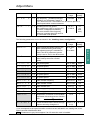
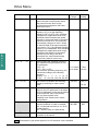
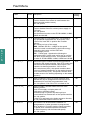
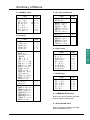
Freq. Ref. FrH Frequency reference
Unit
-
E
N
G
L
I
S
H
Hz
Output Freq.rFr Output frequency applied to the motor
Hz
Motor Speed SPd Motor speed estimated by the speed controller
rpm
MotorCurrent LCr Motor current
A
MainsVoltage ULn Line voltage
V
MotorThermal tHr Thermal state : 100% corresponds to the nominal thermal state
of the motor. Above 118%, the speed controller triggers an OLF
fault (motor overload)
%
DriveThermal tHd Thermal state of the speed controller : 100% corresponds to the
nominal thermal state of the speed controller. Above 118%, the
speed controller triggers an OHF fault (speed controller
overheating). It can be reset below 70 %.
%
Last Fault LFt Displays the last fault which occurred.
-
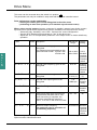
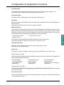
Freq. Ref. LFr This adjustment parameter appears instead of the FrH parameter
when speed controller control via the display module is activated :
LCC parameter in the control menu.
Hz
57