1
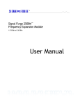
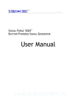
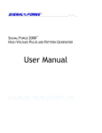
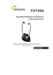
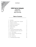
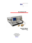
Email: [email protected]
Phone: 512.275.3733
Web: www.signalforge.com
Customer Service Email: [email protected]
Phone: 512.275.3733
Fax: 512.275.3735
Address: Signal Forge, LLC
2115 Saratoga Drive
Austin TX 78733
Table of Contents
INTRODUCTION------------------------------------1
General Features----------------------------------1
Applications -----------------------------------------1
SPECIFICATIONS----------------------------------3
GETTING STARTED ------------------------------5
Power Adapter -------------------------------------5
Connecting the SF800 to Your Computer---5
Front Panel Connections ------------------5
Rear Panel Connections -------------------6
Wave Manager Software ------------------------6
Creating a Waveform -----------------------7
Running the Waveform ------------------- 10
Saving Waveforms ------------------------ 10
Modifying Waveforms “On-The-Fly” -------- 10
Frequency Step Up, Step Down ------- 11
Power Level / Attenuation Control----- 11
OUTPUT TYPES---------------------------------- 12
AC Coupled Output ----------------------------- 12
Differential Output------------------------------- 12
Digital Output ------------------------------------- 13
Operating Limits --------------------------------- 13
Operating Ranges------------------------------- 14
WAVEFORMS ------------------------------------- 15
Single Tone --------------------------------------- 15
FSK Unramped ---------------------------------- 15
FSK Ramped ------------------------------------- 16
FSK Triangle-------------------------------------- 17
FSK Arbitrary Waveform----------------------- 17
Sweep ---------------------------------------------- 18
Square AM ---------------------------------------- 19
Sine AM-------------------------------------------- 19
ARBITRARY WAVEFORMS-------------------21
Arbitrary Modulation Operation --------------21
Waveform Descriptors--------------------------21
Digital Descriptors -------------------------------21
Floating Point Descriptors ---------------------21
Creating a Descriptor File ---------------------22
Digital Descriptors -------------------------22
Sample File ----------------------------------22
Uploading A Modulation File------------------22
AUXILIARY UART--------------------------------24
CALIBRATION ------------------------------------25
EXTERNAL CONTROL HEADER------------26
Connector Descriptions-------------------26
GENERAL SAFETY AND WARRANTY
INFORMATION------------------------------------29
To Avoid Fire or Personal Injury -------------29
Warranty -------------------------------------------29
Table of Figures
Figure 1. Front Panel
Figure 2. Rear Panel
Figure 3. Main Menu of the Wave Manager software.
Figure 4. Waveform Creation Menu.
Figure 5. Select New Waveform menu.
Figure 6. Edit Parameters menu.
Figure 7. Output selection menu.
Figure 8. Edit Parameters menu.
Figure 9. Running the new waveform.
Figure 10. Modify Active Waveform Menu.
Figure 11. Modify Power Setting.
Figure 12. AC Coupled Output Driver
Figure 13. Differential Output Driver
Figure 14. Digital Output Driver
Figure 15. FSK Unramped Modulation
Figure 16. FSK Ramped Modulation
Figure 17. FSK Triangle Modulation
Figure 18. Example of FSK Arbitrary waveform
Figure 19. Sample FSK Arbitrary Text File
Figure 20. Sample Square AM Waveform
Figure 21. Example of Sine AM Waveform
Figure 22. Example of an Arbitrary Modulation file.
Figure 23. Enable Arbitrary Waveform option.
Figure 24. Upload Arbitrary Waveform File.
Figure 25: Auxiliary UART Usage
Figure 26: External Control Header on SF800 Front Panel.
Figure 27: External Control Pin Filter
Figure 28: FSK Control Pin Operation
5
6
7
7
8
8
9
9
10
11
11
12
13
13
16
16
17
18
18
19
20
22
23
23
24
26
27
28
Table of Tables
Table 1 Operating Ranges
Table 2. Sine AM Samples per Cycle Table
Table 3. Arbitrary Waveform: maximum sample rate table.
Table 4. Digital Descriptor Definitions
Table 5. External Control Header
14
20
21
22
26
The Signal Forge 800 Digitally Synthesized Signal Generator is a low-cost, high performance signal source, which
combines several key functions into a single unit: frequency generation, frequency sweep, frequency modulation,
amplitude modulation and arbitrary modulation. A convenient, dedicated output port tailored for testing digital systems
with support for 3.3V TTL, 2.5V TTL and 1.8V STTL voltage levels is also provided. An integral TCXO oscillator
ensures a high level of precision and accuracy.
A wide, stable frequency range with AC coupled single-ended, differential and digital outputs with selectable TTL
voltage levels in a small, easy to use package combine to make the Signal Forge 800 (SF800) the ideal tool for a full
range of RF and digital electronics test and development applications.
!
The Signal Forge 800 supports the following features:
1000 Hz to 800 MHz output, usable to 1GHz
Programmable synthesized frequency source
FSK, AM, OOK, ASK and arbitrary modulation modes
External and internal control of Start, FSK, OOK and ASK
TCXO oscillator provides high level of precision and accuracy
Low parts count makes it highly reliable (as required for ATE systems)
Easy to learn and operate
Microprocessor controlled
Output jitter performance +/-20 ps Pk- to-Pk
Minimal frequency overshoot when changing frequency
Small, portable package (8.5” x 5.5” x 1.5”)
!
The list below shows some of the possible applications where the Signal Forge 800 may be used:
IF and RF sections of receivers as well as the mobile bands up to 1 GHz and some telemetry bands
Test amplifiers for gains and for the 1 dB compression point
Portable, bench top and ATE system applications
Local Oscillator (L.O.) source
Programmable clock generator
Sweep mode of the digital output can be used to test setup and hold of digital systems
FSK and frequency sweep may be used to test FM receivers
Can be used as an amateur or commercial RF exciter
"
"
!
Frequency Range……………………………………. 1000 Hz - 800 MHz, usable to 1 GHz
Frequency Resolution................................................ 1 Hz
Amplitude Resolution................................................. 1 dB
Power Range (AC Output)........................................ –11 to 7 dBm
Power Output Accuracy (AC Output)....................….+/-2 dB over full frequency and power range
Frequency Drift per hour (After warm-up)................. 0.0002 %
Frequency Stability............................................... …. 0.001 % - Over temperature of range of
15-35 ºC ambient
Frequency precision ……………………………….... 4ppm (based on 2.5ppm TCXO)
Frequency accuracy ………………………………… 5ppm (calibrated with a 1ppm frequency
counter)
Frequency stability……………………………………May drift 3ppm in the first year then
1ppm/year thereafter
Phase Noise:
-64 dBc/Hz @ 1 KHz Offset
-90 dBc/Hz @ 10 KHz
-110 dBc/Hz @ 100 KHz
Harmonics:
2 MHz to 50 MHz.......................................< -50 dBc
50 MHz to 100 MHz.....................................< -50 dBc
100 MHz to 500 MHz....................................< -20 dBc
500 MHz to 1GHz........................................ < -20 dBc
Non-Harmonics:
100 KHz to 100 MHz......................…………< -65 dBc
100 MHz to 500 MHz....................................< -60 dBc
500 MHz to 800 MHz....................................< -60 dBc
Clock feed-through.....…............................................ < -85 dBm
Output Match (VSWR)
1 MHz to 7 MHz……….................................< 2:1 @ +7 dBm output
7 MHz to 800 MHz.........................................< 1.3:1 @ +7dBm output
#
External Control Header
Input Voltage………………………………… 3.3V (5V Tolerant)
Output voltage (TX_MOD pin)……………….5V
Output ratings at 100 MHz, 0 dBm output power and 25 ºC, unless otherwise specified.
$
#
&
' (
110V AC power adapter with a 5VDC output is provided. The power connector is on the rear panel. Use only the
power adapter that came with your SF800.
&
)
Attach a standard serial port cable with a DB-9 connector to the RS-232 port on the rear panel of the SF800 and the
other end to the serial port on your computer. Alternatively, the SF800 may be connected to a USB connection on your
computer by attaching an inline Keyspan 19HS serial port-to-USB adapter to the serial port cable.
'
!
Figure 1. Front Panel
Differential Outputs. Two SMA connectors for driving the differential clock output. LVPECL compatible, 50 MHz to
800 MHz range (usable to 1 GHz).
A/C Coupled Output. One SMA connector for driving the AC coupled, sine wave output with a frequency range of 100
KHz to 800 MHz (usable to 1 GHz).
Digital Output. BNC connector. Digital voltage levels supported are: TTL, LVTTL, STTL over a frequency range of
1000 Hz to 100 MHz.
External Control. Dual-row 10-position header provides 10 two-pin connectors for:
Differential Clock On/Off Keying (OOK) control
Frequency Shift Keying (FSK) control
OOK control (for AC Coupled output)
ASK control (AC Coupled output)
Remote START control
LED. The front panel LED will be turned on solid if the SF800 has powered up correctly. If the LED does not turn on,
then a power error has occurred and the SF800 may not be operational. The LED is also turned off during some
operations to signify a change of state.
%
At power-up, all outputs are disabled, unless a waveform has been previously saved and programmed
to automatically start at power up.
'
!
! "#"$% & & $' (" ) "# %
*("# %
# * +
%$
, -!
Figure 2. Rear Panel
RS-232. The RS-232 port uses a standard DB-9 serial connector, which connects the SF800 to the serial port on your
PC. The required RS-232 port settings are: 8 data bits, 1 stop bit and no-parity; flow control: XON/XOFF only, no
hardware handshake pins are implemented. The baud rate must be set to 57,600.
10 MHz Clock. BNC connector that provides a 10 MHz TTL reference signal derived from the internal TCXO
timebase. Output impedance is approximately 50 .
The rear BNC connector for the 10 MHz clock is a reference clock input on the SF800E enabling it to be
driven by an external standard. It is a clock output on the SF800.
Power. Input for the AC power adapter (provided). 5 VDC only.
On/Off. Power on/off button. The LED on the front panel will be on solid if the SF800 has powered up correctly. If the
LED does not turn on, then a power error has occurred and the SF800 may not be operational. In this case contact
technical support for assistance.
+ ,
&
(
Setup, configuration and programming is accomplished using Wave Manager, the embedded, menu-driven software
included with the SF800. The software uses an external serial console (typically a computer monitor) as the display
device. Standard terminal console software, such as Windows HyperTerminal may be used as the console.
At power up, the main menu is displayed, presenting the current configuration, operational status and programming
options. The menu screens are organized such that only the options allowable for the selected waveform and output
type are displayed making the software easy to learn and navigate.
*
Figure 3. Main Menu of the Wave Manager software.
&
+ ,
To configure a new waveform, select the Waveform Creation Menu.
Figure 4. Waveform Creation Menu.
-
First select New Waveform Type and choose the desired waveform from the list.
Figure 5. Select New Waveform menu.
Hit ESC to return to the main Waveform Creation Menu, then select Edit Parameters.
Figure 6. Edit Parameters menu.
Then select Output from the menu to configure the output type from the list displayed.
Figure 7. Output selection menu.
Figure 8. Edit Parameters menu.
Hit ESC to return to the main Edit Parameters menu and configure all other applicable parameters such as frequency,
output power, etc.
External Controls. The Edit Parameters menu also allows you to enable the external controls, where applicable. See
the External Controls section for a description of the external control connector.
The Arbitrary Modulation selection enables you to upload a file containing a user defined modulation
pattern. See the Arbitrary Modulations and Arbitrary Waveforms chapter below for information on
creating an Arbitrary Modulation file.
.
Entering a frequency value greater than the maximum supported will be flagged as an error or
automatically reset to the highest valid value.
Figure 9. Running the new waveform.
&
+ ,
Return to the main Waveform Creation menu and select Run to start the new waveform. You may run the waveform
with or without saving it.
, &+ ,
!
From the Waveform Creation menu, you may chose to save the new waveform to one of the four non-volatile memory
locations.
You also have the option to save your waveform with the Load at Power-up option. The Load at Power Up feature
causes the selected waveform to be loaded and started when the SF800 is first turned on. This feature enables the
SF800 to operate in a repeatable stand-alone mode.
Saving a new configuration overwrites any previously saved configuration at that location.
In addition to the four memory locations, one set of user-developed arbitrary waveform data may be saved (see the
Arbitrary Waveform Modulation section below).
/ &+ ,
! 01 2
2 /3
Some of the parameters of the Single Tone and FSK type waveforms may be modified during runtime providing you
with increased flexibility to exercise specific areas of the device under test.
Figure 10. Modify Active Waveform Menu.
4
/
5
6 (
While either the Single Tone or FSK type waveform is running, the frequency may be changed by stepping it up or
down in discrete steps using the selections on the Modify Active Waveform menu (in the case of FSK, Frequency 1 is
changed only). The frequency may be repeatedly stepped up or down in increments of 1 Hz, 10 Hz or 100Hz. You may
also enter a new frequency value by using menu selection [F].
' (
,
7
89
9 !
1 ! :
The Wave Manager software allows you to change the Base power level and the Offset during operation when the AC
Coupled output is enabled. The power values are entered in dBm.
Base Power (dBm Base). Base power may be increased or decreased within the supported range, which is -11
dBm to +7 dBm.
Offset. Allows you to adjust the Base Power to offset the losses of external connections (i.e. interconnect cables).
For example: You enter a frequency of 500 MHz and require an output of 5 dBm; you then enter an offset of 2 dB
causing the SF800 to drive the output at 7dBm. After a cable loss of 2 dBm, the output power measured at the
Device Under Test should be 5 dBm (7-2 = 5 dBm) In all cases; the total power must not exceed the maximum
dBm provided by the SF800.
Figure 11. Modify Power Setting.
$
1
/ !
The SF800 provides three different output types:
AC Coupled, Single-ended
Differential
Digital
All outputs have a resolution of 1Hz.
When an output type is selected, all other output types are disabled (e.g. when AC Coupled is selected, the TTL output
is tri-stated and the differential output is at 0 MHz).
1
The output driver of the AC Coupled signal source provides a nominal 50-Ohm output impedance–the output driver
implementation is described in the drawing below.
Figure 12. AC Coupled Output Driver
6
1
The outputs of the differential driver conform to the LVPECL standard. The driver and the recommended method of
interfacing to it are described in the drawing below. This differential driver is designed to work in 50-Ohm systems.
"
!"
# "!
Figure 13. Differential Output Driver
6&
1
The following block diagram shows the implementation of the programmable TTL output buffer:
( )*
'
$$
(
+$
*
%
$
&
$
+
Figure 14. Digital Output Driver
1
&
AC Coupled output
Differential output
!
100 KHz - 800 MHz (usable to 1 GHz)
50 MHz - 800 MHz (usable to 1 GHz)
Digital (TTL) output
1000 Hz - 100 MHz
Internal Max FSK deviation range is as follows:
o
Digital (TTL)
Any deviation allowed
o
AC Coupled from 1 Hz to 100 MHz
Any deviation allowed
o
AC Coupled above 100 MHz
Deviation ±1% max
o
Differential
Deviation ±1% max
o
The duty cycle (Frequency1 direction)
10% to 90%
External OOK/FSK (User-driven signal)
4.5 KHz maximum
Internal OOK
500 KHz maximum
OOK is supported for:
o
AC Coupled output
Up to 100 MHz
o
Differential output
Full range
o
The duty cycle (ON percentage)
10 to 90% except near the highest
modulating frequency
#
1
&
& !
Waveform / Operation
Range
OOK
Modulating frequency 0.1 Hz to 500 KHz
FSK ramped / unramped
Modulating frequency 0.1 Hz to 500 KHz
FSK Arbitrary
Modulating frequency 0.1 Hz to 26 KHz
Sweep
Frequency changes using step time of 10ms to 60s in 1ms
increments
Square AM wave
Modulating frequency 0.1 Hz to 45 KHz
Sine AM wave
Modulating frequency 0.1 Hz to 65 K Hz
Table 1 Operating Ranges
$
%
+ ,
!
The SF800 provides a wide range of waveform modulation features from which you can create a variety of waveforms.
Numerous waveform modifiers may be applied to customize the output to meet your specific testing needs. The
waveforms, modifiers and options are configured using the Wave Manager software.
In addition, you may develop arbitrary modulation files to create your own unique type of FSK or AM modulated output.
An Arbitrary Modulation option will be displayed on the Edit Parameters screen of any waveform that supports userdeveloped waveform modulation files.
&
The Single Tone waveform outputs a continuous tone at the user-selected output frequency.
Output types
AC Coupled
Differential
Digital (TTL: 3.3V, LVTTL: 2.5V, SVTTL: 1.8V)
Options
Externally or internally controlled OOK
Externally controlled Start
External control requires an external user-provided modulating source (TTL level).
;
The Frequency Shift Keying (FSK) Unramped waveform allows you to select two output frequencies which are
alternately driven at a preprogrammed rate. For internal FSK operation, the modulating frequency that determines the
rate at which the frequencies change is selected from the Edit Parameters menu. The duty cycle menu entry
determines the duration that frequency1 is asserted versus frequency2. The alternate frequency selection is
determined either by internal timers, or by the front panel FSK signal (when external control is enabled).
%
. * !( /
,
,
( -
( - $
,
( -
Figure 15. FSK Unramped Modulation
Output types
AC Coupled
Differential
Digital (TTL: 3.3V, LVTTL: 2.5V, SVTTL: 1.8V)
Options
Externally controlled OOK
Externally controlled Start
Arbitrary modulation (from a user created file)
;
The FSK Ramped waveform varies the output frequency within a specified range. The rate of frequency change is
determined by the delta frequency (the amount that the frequency is changed at each step) and the ramp rate (at what
interval the frequency is changed).
The direction of frequency change is determined by internal timers or by the front panel FSK signal (when external
control is enabled). For internal FSK operation, the modulating frequency and duty cycle determine how long
frequency1 and frequency2 are selected. When frequency2 is selected, the direction of change is towards frequency2.
Once frequency2 is reached, the frequency will remain there until the internal timer signal selects frequency1 (which
causes the frequency to ramp towards frequency1).
The user would normally select a modulating frequency and duty cycle such that the ramp has time to complete (i.e. If
the FSK signal changes before the ramp is complete, then you will not have reached full range). See drawing below:
. * !( /
,
,
( - $
0
1 #
,
( -
Figure 16. FSK Ramped Modulation
*
*
,
( -
Output types
AC Coupled
Differential
Digital (TTL: 3.3V, LVTTL: 2.5V, SVTTL: 1.8V)
Options
Externally controlled OOK
Externally controlled Start
Arbitrary modulation (from a user created file)
;
&
FSK Triangle is similar to FSK ramped, except that ramping from one frequency to the next occurs automatically.
When an end frequency is reached, the direction changes and ramping continues towards the other frequency. See
drawing below:
,
( - $
0
1 #
,
*
,
( -
Figure 17. FSK Triangle Modulation
Output types
AC Coupled
Differential
Digital (TTL: 3.3V, LVTTL: 2.5V, SVTTL: 1.8V)
Options
Externally controlled OOK
Externally controlled Start
Arbitrary modulation (from a user created file)
;
<
/+ ,
For FSK Arbitrary Waveforms, a user developed file describing a set of frequency variations is uploaded to the SF800
and optionally saved in internal non-volatile memory. One arbitrary data set may be saved at a time.
FSK Arbitrary descriptor files may be created using a text editor or waveform generator software.
Arbitrary FSK allows the user to specify a set of frequency variations, the user-entered data includes:
Center frequency
-
Maximum deviation
Sample rate
A set of descriptors that define the deviation for each sample point
The output frequency changes at a time defined by the sample rate. The actual output frequency is determined using
the formula
Fout = <center frequency > + (deviation * descriptor)
Where each descriptor is a floating point value in the range –1.0 to 1.0. For example, a center frequency of 50 MHz
with deviation 10 MHz and descriptor -0.5 will create a frequency of 45 MHz.
The file format and number of descriptors supported is described in the Creating Arbitrary Waveforms chapter below.
The drawing below illustrates how FSK Arbitrary Waveforms operate.
,
( -
2
2$
2$
2
Figure 18. Example of FSK Arbitrary waveform
The FSK waveform shown above was created from the following text file:
!
"
Figure 19. Sample FSK Arbitrary Text File
(
Sweep is similar to the FSK ramped mode of operation except that it allows frequencies to span the full operational
range. It also allows any delta frequency. Sweep allows the user to pause, change direction, or single-step. When a
sweep range completes, it starts over at the first frequency.
Output types
AC Coupled (single-ended)
Differential
Digital (TTL: 3.3V, LVTTL: 2.5V, SVTTL: 1.8V)
Options
Externally controlled or OOK
Externally controlled Start
4
For Square AM, the user specifies a single frequency (the carrier frequency) and two power values. The duty cycle
may be programmed to a value other than 50%, which will result in the creation of an asymmetrical wave instead of a
square wave (50% at the first power value and 50% at the lower power value). The drawing below depicts AM Square
Wave operation (in this example, the modulation is set to 50%)
. * !( /
, ( 4 ,
6 " 5
'
4 (
3
!( . '
*
5
(
3
(" * 0
4!( . ' 5
Figure 20. Sample Square AM Waveform
Arbitrary waveform modulation may be used to completely customize an AM type waveform by downloading arbitrary
amplitude descriptors from a user-generated file.
Output types
AC Coupled
Options
Externally controlled OOK
Externally controlled Start
Arbitrary modulation (from a user created file)
A Sine Wave AM waveform modulates power using a sinusoidal pattern. The SF800 outputs a discrete number of
power levels as shown in the drawing below. The existence of these discrete power steps is normally not an issue
since an AM demodulator includes a low pass filter at its output that will remove any high frequency components
(higher than the maximum modulating frequency).
.
. * !( /
4 !( 6
00 7!
!
, ( "
! (5
,
( -
'
4 (
3
!( . '
5
00
!
3
(" * 0
4!( . ' 5
Figure 21. Example of Sine AM Waveform
Output types
AC Coupled
Options
Externally controlled OOK
Externally controlled Start
Arbitrary modulation (from a user created file)
The modulating frequency affects the number of sample points that are used to create the waveform as shown in the
following table:
Modulating frequency
Samples per cycle
7500 Hz
12
2500 Hz
36
1500 Hz
60
750 Hz
120
500 Hz
180
250 Hz
360
Table 2. Sine AM Samples per Cycle Table
The Arbitrary Modulation mode may be used to completely customize an AM waveform by downloading a usergenerated arbitrary descriptor file. In this case, each descriptor defines the output power using values of –1.0 to 1.0,
where –1.0 is the lowest power and +1.0 is the highest power.
Maximum Square AM modulating frequency is 40 KHz. Maximum Sine AM modulating Frequency is 66
KHz.
"
*
<
/+ ,
!
Arbitrary Waveforms allow the user to define specific frequency or power values at a specified sample rate. CHIRP
testing can be executed easily with the SF800 by creating the appropriate arbitrary waveforms. The following sections
describe how to create, upload and save Arbitrary Modulation files to the SF800.
An Arbitrary Modulation selection will be displayed on the Edit Parameters menu of all waveforms that support arbitrary
modulation.
<
/
1
The Arbitrary Modulation mode of operation enables you to specify data points that describe a waveform and the rate
of execution. The maximum rates are shown in the following table.
Operation
Sample Rate
OOK
90 KHz
FSK
90 KHz
Square AM
80 KHz
Sine AM
80 KHz
Table 3. Arbitrary Waveform: Maximum Sample Rate.
+ ,
6 !
!
Two types of descriptors are supported: digital and floating point.
6&
6 !
!
Digital descriptors are used in cases where the output is only in one of two states, such as on/off or frequency high/low.
Up to 2048 digital descriptors are supported. For example, digital descriptors would be used for OOK operation or
Square Wave AM.
Digital descriptors may be in floating point or integer format where values greater than 0 are considered TRUE and
other values are considered FALSE.
&'
6 !
!
Floating-point descriptors are used in cases, such as FSK Arbitrary or Sine AM, where the output is in more than two
states. Up to 512 floating point descriptors are supported.
Floating point descriptors must be in the range –1.0 to 1.0, and are used to define the amount of deviation to apply at
each sample point. The output is determined by multiplying the descriptor and deviation, then adding the result to the
center value.
"
&
An Arbitrary Modulation file must comply with the following criteria. The file may be created using a text editor, or any
program that creates an ASCII file:
One line should contain the keyword “number_of_points “ followed by the number of sample points described (e.g.
“number_of_points 22”). This may be on any line.
Sample points separated by spaces, commas, or tabs
Comments may be inserted anywhere in the file starting with any character other than characters used for numbers
(“0123456789.+-“), or matching the keyword “number_of_points”. When a comment character is recognized, the rest of
the line is ignored.
The file must contain, at a minimum, the number of sample points indicated on the “number_of_points” line. If you
include more samples than specified, they will be ignored.
6&
6 !
!
Operation
Description
OOK
FALSE means output is OFF, else ON
FSK
FALSE means output frequency one, else frequency two
AM square wave
FALSE means output low power, else high power
Table 4. Digital Descriptor Definitions
The following sample file describes how to create a floating point set of data points to control an FSK type or AM sine
wave type of output:
// file sine.txt
// Half Sine wave data points for FSK arbitrary or Sine AM
number_of_points 15
-1.0 -.8 -.6 -.4 -.3 -.2 -.1 0
.1 .2 .3 .4 .6 .8 1.0
Figure 22. Example of an Arbitrary Modulation file.
&
Once created, the Arbitrary Modulation file may be uploaded to the SF800 and optionally saved in its non-volatile
memory.
Before uploading the file, you must first setup the waveform that will be modulated by your set of arbitrary data points.
There are two ways to setup the waveform:
Select either the FSK Arbitrary waveform from the New Waveform Type menu
ENABLE Arbitrary Waveform from the Edit Parameters menu (where applicable).
Once enabled, an Upload Arbitrary Modulation File selection will appear on the Edit Parameters menu.
""
Figure 23. Enable Arbitrary Waveform option.
Next select Upload Arbitrary Waveform File and follow the onscreen instructions.
Figure 24. Upload Arbitrary Waveform File.
If you wish to save the arbitrary data to non-volatile memory, use the save option before exiting the
arbitrary modulation menu.
"#
=
/
The SF800 provides a transmit only UART port (TX_MOD – pin 8) that may be used to send ASCII data characters to
an internal or external modulation device. This port is completely separate from the UART port used for the console.
The data that is sent by the auxiliary UART port can be ASCII data generated by a keyboard or from a file. The baud
rate is programmable at these rates: 2400, 4800, 9600, 19200, 38400, and 57600 baud.
The Wave Manager software provides support for this UART port on the Auxiliary UART Menu (under the Modify
Active Menu entry).
You may connect the Auxiliary UART output using the appropriate filtering/interface (i.e. polarity control) to an external
modulating device or to the OOK/FSK control pins of the same SF800. In this way, you can create modulated
waveform outputs, which are actually encoding UART driven data. The diagram below depicts how to configure the
UART TX_MOD pin to create an ASCII data keyed OOK Waveform:
AC Coupled
(Output)
SF800
OOK Pin
(Input)
External Control
Header
TX_MOD pin
(Output)
Figure 25: Auxiliary UART Usage
"$
Optional External
Filtering or Control
<
The user has the option to calibrate the SF800 against a known accuracy time base standard at any time. The
accuracy of the device used to get the frequency determines the accuracy of the SF800.
The Calibration entry can be found in the Main Menu and may be performed as follows:
1. Connect the SF800 to a frequency counter.
2. Enable a TTL or AC Coupled output with a frequency in the range of 1 MHz
100 MHz (10 MHz is a common standard but the SF800 does not limit the user to this frequency value).
to
3. Select "Calibration" from the Main Menu.
4. Enter the frequency as indicated by the external frequency counter. The difference between these
frequencies is used to determine the required calibration. Calibration information is stored by the SF800 in
non-volatile memory, loaded at power up, and used until the device is calibrated again.
"%
.
=
>
The SF800 provides ten 2-pin connectors in a header labeled External Control on the front panel. These
connectors enable you to control several modulation functions, such as frequency shift keying (FSK) or On/Off
Keying (OOK). The function assignments are listed below.
POSITION
NAME
(bottom row)
POSITION
NAME
(top row)
1
Reserved
1
Reserved
2
DIFF OOK
2
GND
3
FSK
3
GND
4
TX_MOD
4
GND
5
SE OOK
5
GND
6
CHIRP/Reserved
6
GND
7
5V
7
ASK
8
5V
8
GND
9
START
9
GND
10
Reserved
10
GND
Table 5. External Control Header
;
:
(
( *
0
3
9
8
'
7
$
3
( *
(
*
Figure 26: External Control Header on SF800 Front Panel.
6 !
!
DIFF OOK. The differential clock output supports OOK for the frequency range of 50 MHz to 800 MHz (usable to 1
GHz). This input pin controls the differential output: driving this pin low will stop the differential output. By default this pin
is set to a high state.
FSK. This pin allows the user to shift the frequency output as defined previously using the menu entry. This pin is
normally high. Driving it low enables you to slow the output frequency as required.
"*
TX_MOD. This is the TX output from the internal Auxiliary UART port. The Wave Manager software provides support
for this UART port on the Auxiliary UART Menu (under the Modify Active Menu entry). The user can connect this
output, using the appropriate filtering/interface to the OOK or FSK external control pins of the SF800 and create UART
data modulated waveforms if so desired.
SE OOK. The SF800 supports OOK (On/Off Keying) for the AC Coupled output in frequency range of 1 Hz to 100
MHz only. This input pin provides for external control of the output: placing this pin low stops the output of the SF800.
This pin is normally set to a high state.
ASK. This control pin allows you to modulate the AC Coupled output in order to implement an externally controlled
Asynchronous Shift Keying. When this pin is driven low the AC coupled output will be attenuated by 16 dB over the full
output power (when the signal is high).
START. External START is an output control option. A high to low transition causes the SF800 to start outputting its
preprogrammed frequency. This feature is available for the AC Coupled, Differential and TTL outputs. When waiting for
START the front panel LED is OFF until a valid START polarity is received. FSK unramped or triangle waveforms with
external FSK control do not support the wait for START (output is as selected by the FSK external control pin).
The time from assertion of the START signal to output valid will vary depending on the type of output/frequency chosen
and modifiers used. The user must first measure this time delay and account for it - if it will affect the type of operation
being performed.
As described above, the SF800 gives you the ability to control the output frequency using external control pins. Each
one of the control pins has a low pass filter placed at its input, except the Start pin. The low pass filter has a 3 dB cutoff
point of 4800 Hz. The input signals must be driven by 3.3V compatible signals. Input impedance is 2K ohms.
The External Control inputs are 5V tolerant and include a certain level of protection as described in the following block
diagram:
3.3V
Input
LPF
Diode
Protection
Figure 27: External Control Pin Filter
"-
The Figure below gives an example of external control of a waveform. In the example chosen, an external signal
controls the FSK signal pin of the SF800.
<
,
!(
( - $
,
( -
Figure 28: FSK Control Pin Operation
"
/
+
/
Only qualified service personnel should perform service procedures.
,
! '
' !
? /
@Use only the power module provided with this product.
' (
6!
'
/. Do not connect or disconnect external header pin leads while they are
connected to a voltage source (turn the SF800 and external control logic simultaneously).
&!. Consult the product manual for ratings information before making connections to the
1<! ,
product.
6
1
6
1
, . Do not operate this product with the cover removed.
+
+
!
!. If you suspect there is damage to this product, have it inspected by
&
& . No not operate this product outside the operating ranges specified on the
qualified service personnel.
1
+
1
manual.
6
+
6
;
+
1
76
=
'
!@
!,
!
!
@
6 /@
/
Signal Forge warrants that the products that it manufactures and sells will be free from defects in materials and
workmanship for a period of one (1) year from the date of shipment. If a product proves defective within the respective
period, Signal Forge will repair or replacement the product without charge.
EXCEPT AS PROVIDED HEREIN, SIGNAL FORGE MAKES NO WARRANTY OF ANY KIND, EXPRESS OR
IMPLIED, INCLUDING WITHOUT LIMITATION THE IMPLIED WARRANTIES OF MERCHANTABILITY AND
FITNESS FOR A PARTICULAR PURPOSE. IN NO EVENT SHALL SIGNAL FORGE BE LIABLE FOR INDIRECT,
SPECIAL OR CONSEQUENTIAL DAMAGES.
".
#
#
!"
#
!
,@
2005 Signal Forge, LLC
2115 Saratoga Drive • Austin TX 78733
Phone 512.275.3733 • Fax 512.275.3735
www.signalforge.com
#"