1
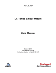
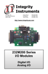
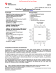
TM TM SIGNAL FORGE 1010 PORTABLE SIGNAL GENERATOR WITH REMOTE CONTROL User Manual … Technical Support Email: [email protected] Phone: 512.275.3733, option 2 Contact Information Web: www.signalforge.com Customer Service and Sales Email: [email protected] Phone: 512.275.3733, option 1 Fax: 512.275.3735 Address: Signal Forge, LLC ▪ 2115 Saratoga Drive ▪ Austin TX 78733 Table of Contents INTRODUCTION------------------------------------------------------6 Features ---------------------------------------------------------------6 Applications -----------------------------------------------------------7 Programming Interface---------------------------------------------7 SCPI Conformance Information ---------------------------------7 SPECIFICATIONS----------------------------------------------------8 CONNECTIONS----------------------------------------------------- 10 Front Panel Connections ---------------------------------- 10 Rear Panel Connections ----------------------------------- 11 GETTING STARTED ---------------------------------------------- 11 Power Adapter ----------------------------------------------------- 11 Connecting the SF1010 to Your Computer ----------------- 11 Using EZ Wave ---------------------------------------------------- 12 Creating Macros---------------------------------------------- 15 Custom Programming -------------------------------------------- 15 Quick Facts---------------------------------------------------- 15 OUTPUT TYPES---------------------------------------------------- 17 RF (AC Coupled) Output ---------------------------------------- 17 Differential Output------------------------------------------------- 18 Digital Output ------------------------------------------------------- 18 OPERATING LIMITS ---------------------------------------------- 19 Output Signal Frequency ---------------------------------- 19 Waveform Modulation Limits------------------------------ 19 LIST Command (Arbitrary Waveform)------------------ 21 Hardware Limits ---------------------------------------------- 21 Hardware Tracking and Locking ------------------------- 21 Firmware Modulation Accuracy -------------------------- 21 WAVEFORM DESCRIPTIONS---------------------------------- 22 Single Tone --------------------------------------------------------- 22 Arbitrary-------------------------------------------------------------- 22 ASK ------------------------------------------------------------------- 22 BPSK ----------------------------------------------------------------- 23 Chirp ------------------------------------------------------------------ 24 Pulsed Chirp (Pulsed FM)--------------------------------------- 24 FSK Ramped ------------------------------------------------------- 25 FSK Triangle-------------------------------------------------------- 25 FSK Unramped ---------------------------------------------------- 26 OOK ------------------------------------------------------------------ 26 Sweep ---------------------------------------------------------------- 27 CALIBRATION ------------------------------------------------------ 28 EXTERNAL CONTROL CONNECTOR----------------------- 29 Recommended Cables/Connectors--------------------- 29 External Connector Pin Description--------------------- 30 GENERAL SAFETY AND WARRANTY INFORMATION 32 To Avoid Fire or Personal Injury ------------------------------- 32 Warranty ------------------------------------------------------------- 32 SF1010E -------------------------------------------------------------- 33 Clock Requirements----------------------------------------- 33 Reconfiguring SF1010E to SF1010 --------------------- 33 POWER CONVERSION TABLES ----------------------------- 35 SOFTWARE UPDATE PROCEDURE ------------------------ 37 PRODUCT LINE ---------------------------------------------------- 38 Table of Figures Figure 1. Front Panel 10 Figure 2. Rear Panel 11 Figure 3. EZ Wave Initialization Window 12 Figure 4. Waveform Selection Window 13 Figure 5. Fixed Frequency Window 14 Figure 6. Sweep Waveform Window 14 Figure 7. Arbitrary Waveform Window 15 Figure 8. RF (AC-Coupled) Output Driver 17 Figure 9. Differential Output Driver 18 Figure 10. Digital Output Driver 18 Figure 11. ASK Operation 23 Figure 12. BPSK Operation 24 Figure 13. Pulsed Chirp Operation 25 Figure 14. FSK Ramped Modulation 25 Figure 15. FSK Triangle Modulation 26 Figure 16. FSK Unramped Modulation 26 Figure 17. External Control Header Pin Locations 29 Figure 18. External Control Pin Filter 31 Figure 19. FSK Control Pin Operation 31 Figure 20. FSK Control Pin Operation 33 Figure 21. SF1010 to SF1010E Jumper Positions 34 Figure 22. Voltage Definitions 36 Table of Tables Table 1 - LIST (Arbitrary) Dwell Times 21 Table 2 - Hardware Limits 21 Table 3 – Tracking and Lock Time 21 Table 4 - Firmware Modulation Accuracy 22 Table 5. External Control Header Pinout 29 Table 6. Configuration Jumpers 33 Table 7. RF Power Conversion Table 36 Table 8 Signal Forge Product Line 38 S F 1 0 1 0 U S E R M A N U A L Chapter 1 Introduction The Signal Forge 1010 Portable Signal Generator with Remote Control is a small, high performance signal source incorporating the SCPI (Standard Commands for Programmable Instruments) interface. The SF1010 features a frequency range of up to 1 GHz. RF, digital and differential outputs support numerous waveform modulation functions. The SF1010 can be controlled using the EZWave software supplied with the unit, or via user-developed software utilizing SCPI commands. SCPI support makes the SF1010 ideal for applications in which the signal generator needs to be controlled by a userdeveloped test program or integrated with an automated test environment (ATE). The SF1010 can be controlled remotely © using software such as LabView , LabWindows/CVI or HP VEE. SCPI is a set of common commands in ASCII text that are sent to the SF1010 over an RS-232 serial connection. SCPI support is described in a separate SCPI Programmers Manual (available for download from the Support page of the Signal Forge web site www.signalforge.com). EZWave is a Microsoft Windows compatible program that operates as the front panel of the generator. It graphically incorporates almost all of the generator functions into logical operations such as sweep and FSK. EZWave has many advanced features for normal lab use and features to assist those writing their own control program. For example, a command capture feature displays the messages sent between the host PC and the signal generator. Features The SF010 supports the following features: SCPI programming interface for integration with LabView or other test environments 1 Hz to 1 GHz frequency range RF (AC-coupled), Digital and Differential outputs Sine wave ASK, BPSK, CHIRP, FSK, OOK, SWEEP modulation modes Arbitrary (user-specified) modulation combines ASK, BPSK, FSK, and OOK. Trigger input for chirp, sweep and arbitrary modulation control SYNC output for triggering on frequency steps (chirp, sweep, arbitrary) Alert message signals end of chirp, sweep, or arbitrary point step Auto Start – a power-up macro feature ideal for PC–free test operation Signal stability of 1ppm and accuracy of 4ppm Small, portable package (8.5in x 5.4in x 2.5in) , square wave 6 S F 1 0 1 0 U S E R M A N U A L Applications The SF1010’s portable size and wide frequency range are ideal for numerous field test applications such as: Installing and maintaining in-building wireless networks and cellular phone systems Digital output in sweep mode can be used to test setup and hold of digital systems—ICs and circuit boards—up to 110 MHz Differential output can used to test digital systems—ICs and circuit boards—up to 1 GHz Programmable clock generator Testing IF and RF sections of receivers as well as the mobile bands up to 1 GHz and some telemetry bands Test amplifiers for gain and for the 1 dB compression point Portable, bench top and ATE system applications Local Oscillator (L.O.) source Receiver calibration FSK and frequency sweep may be used to test FM receivers RF exciter Test low frequency filters (down to 1 Hz) BPSK may be used to test low data-rate applications such as IEEE 802.11g wireless LAN standard, RFID and Zigbee devices Programming Interface The SF1010’s instrument programming interface complies with the IEEE488.2 and SCPI-1999.0 standards. IEEE488.2-2004 (Standard Digital Interface for Programmable Instrumentation) describes how to send commands to instruments and how to send responses to controllers. It defined some frequently used “housekeeping” commands explicitly, but each instrument manufacturer was left with the task of naming any other types of command and defining their effect SCPI 1999.0 Standard Commands for Programmable Instruments (SCPI) is the new instrument command language for controlling instruments that goes beyond IEEE 488.2 to address a wide variety of instrument functions in a standard manner. SCPI promotes consistency, from the remote programming standpoint, between instruments of the same class and between instruments with the same functional capability. For a given measurement function such as frequency or voltage, SCPI defines the specific command set that is available for that function. SCPI Conformance Information Unless otherwise specified, commands and queries are performed as described by the SCPI standard. The response for commands (not queries) is not SCPI compliant. A SCPI command response normally consists only of a terminator. This instrument first sends a one-character ‘0’-‘9’ to indicate the number of errors in the error queue. See the protocol section for specifics. For complete programming information, refer to the SCPI Programmer’s Manual which may be downloaded from the Support page of the Signal Forge Web site. To obtain a hardcopy of the manual, send a request to Signal Forge at [email protected]. 7 S F 1 0 1 0 U S E R M A N U A L Chapter 2 Specifications Frequency Range RF (AC-coupled) Output…………………... 1 KHz – 1 GHz Digital Output……………………………….. 1 Hz - 110 MHz Differential Output………………………….. 50 MHz to 1 GHz Frequency Resolution................................................ 1 Hz Frequency Drift per hour (After warm-up)................. 0.0002 % Frequency Stability............................................... …. 0.001 % - Over temperature of range of 15-35 ºC ambient Frequency Accuracy.…………………………………4ppm (based on ± 2ppm TCXO) Frequency Stability……………………………………1ppm/year after the first year May drift 3ppm in the first year External Control Header Input Voltage……………………………….. 3.3V (5V Tolerant) Output voltage (TX_MOD pin)…………….. 5V Operating Voltage ……………………………………10V min to 15V max Operating Current………………………………….… 600mA min to 700mA max Operating Power Supply…………………………….. Input 100/ 240VAC, 50/60 Hz Output of 15 VDC and 1.0A. (provided) RF (AC Coupled) Output Amplitude Range……………………………………..143 mVp-p to 1414 mVp-p Amplitude Resolution................................................. 1 dB Power Range (RF Output)........................................ -12 dBm to +12 dBm Power Output Accuracy (RF Output)....................….±2 dB from 100 KHz to 300 MHz ±3 dB from 300MHz to 1 GHz Phase Noise ≤100 MHz -50 dBc/Hz @ 10 KHz Offset -73 dBc/Hz @ 100 KHz -90 dBc/Hz @ 1000 KHz 8 S F 1 0 1 0 U S E R Phase Noise M A N U A L >100 MHz -20 dBc/Hz @ 10 KHz Offset -60 dBc/Hz @ 100 KHz -90 dBc/Hz @ 1000 KHz Harmonics 2 MHz to 50 MHz............................< -40 dBc 50 MHz to 100 MHz.......................< -40 dBc 100 MHz to 3500 MHz....................< -20 dBc 300 MHZ to 500 MHz……………..<- 20dBc 500 MHz to 1GHz...........................< -20 dBc Non-Harmonics 100 KHz to 100 MHz...................... < -50 dBc 100 MHz to 500 MHz......................< -30 dBc 500 MHz to 1GHz….......................< -30 dBc Clock feed-through.....….............................................< -85 dBm Output Match (VSWR) 1 MHz to 7 MHz………..................< 1.5:1 @ +7 dBm output 7 MHz to 1 GHz….......................... < 1.3:1 @ +7dBm output Operating Temperature.....….................................... 0ºC to 50 ºC Note Output ratings at 100 MHz, 0 dBm output power and 25 ºC, unless otherwise specified Note For maximum stability, allow the SF1010 to warm up (soak) for 1 hour before use. 9 S F 1 0 1 0 U S E R M A N U A L Connections Front Panel Connections SIGNAL FORGE 1010 Portable Signal Generat or with Remote Control Figure 1. Front Panel Differential Outputs. Two SMA connectors for driving the differential clock output. LVPECL compatible, 50 MHz to 1 GHz. RF Output. One SMA connector for sourcing the AC coupled, unfiltered, sine wave output with a frequency range of 1 KHz to 1 GHz. The AC coupled output is capacitively connected to the output allowing the sine wave output to be floated at any level desired. Digital Output. BNC connector. Digital voltage levels supported are: TTL, LVTTL, STTL over a frequency range of 1 Hz to 110 MHz. External Control. Dual-row 10-position header provides connections for: Frequency Shift Keying (FSK) control Binary (or Bipolar) Phase Shift Keying (BPSK) control On/Off Keying (OOK) control for the Differential Output OOK control for the AC-coupled output ASK control (RF output only) TRIGGER control input used to optionally control some waveforms SYNC output (for triggering on a certain portion of waveforms) The recommended connectors for the External Control are: - 20-pin connector and cable assembly. May be purchased from Signal Forge. See the Accessories section of the Signal Forge Product page at www.signalforge.com. - 2-pin connector housing and contacts for use if not all control signals are needed - o 2-position housing p/n: A26921-ND o Contacts (2 required) p/n: A26951-ND The connectors may be purchased from www.Digi-Key.com. 10 S F 1 0 1 0 U S E R M A N U A L Rear Panel Connections Figure 2. Rear Panel RS-232. The RS-232 port is a female DB-9 serial connector, which connects the SF1010 to the serial port on your PC. Only the TX, RX and GND pins of the DB9 connector are implemented on the SF1010. RS-232 cables and USB to RS-232 serial adapters may be purchase from Signal Forge. 10 MHz Clock. BNC connector that provides a 10 MHz TTL reference output signal derived from the internal TCXO timebase. Output impedance is approximately 50 Ω. The accuracy of the 10 MHz output is 0.83 ppm. This square wave clock output has 70/30 symmetry Note The rear BNC connector for the 10 MHz clock is a reference clock input on the SF1010E enabling it to be driven by an external standard. It is a clock output on the SF1010. Power. The AC adapter provides 15VDC and 1.0A output; Input range 100-260V, 50/60 Hz. Front Panel LED. The front panel LED begins blinking when the unit is first turned on. It continues to blink for a few seconds while control remains in the boot portion of FLASH. After a few seconds of blinking, control is transferred from the boot portion to the application portion of FLASH. At this time the LED stays ON and does not blink. Getting Started Power Adapter An AC power adapter is provided. The specifications are: Input 100-240V, 50/60 Hz; Output +15VDC, 1.0A. The power connector is on the rear panel. Use only the power adapter that came with your SF1010. Note: The operating requirements of the SF1010 are: 10V to 15V, 700mA. Connecting the SF1010 to Your Computer 1. Make the physical PC to instrument connection Serial Port: Attach a standard serial port cable with a male DB-9 connector and straight through pin out to the RS-232 port on the rear panel of the SF1010 and the other end to the serial port on your computer. Standard serial cables may be purchased many sources including Signal Forge. USB: To connect your computer to the SF1010 via USB connection, use an inline serial port to USB adapter. A USB to serial adapter is available from the Signal Forge web site, www.signalforge.com. 11 S F 1 0 1 0 U S E R M A N U A L 2. Install the EZ Wave software on your Windows PC. “Installation” of EZ Wave entails simply copying the program to your desktop or a directory of your choice. EZ Wave is compatible with all Windows operating systems except Windows 95 and NT. Support includes Vista, XP, ME, 98, Win2000, and Server 2003 Configure EZ Wave as follows: Select any available COM port EZ Wave automatically configures the COM port for proper operation (8 data bits, 1 stop bit, no-parity, no flow control, baud rate 115,200). Using EZ Wave EZ Wave software is a Windows-based application compatible with all Windows operating systems except Windows 95 and NT (support includes Vista, XP, ME, 98, Win2000, and Server 2003). EZWave provides easy control of the SF1010 without the need for custom programming. The SF1010 should first be connected to your computer and turned on, then delay a few seconds until the LED stops blinking. Start EZ Wave, select any available COM port and the main menu is displayed. The current output state of the SF1010 is displayed along the bottom bar of the main screen. Click on the Initialize button and the programming options on the main menu become active. Note that the screens are organized such that only the options allowable for the selected waveform and output type are displayed making the software easy to learn and navigate. Figure 3. EZ Wave Initialization Window When you select the type of waveform you wish to setup, a configuration window will popup and display the configuration options available for the selected waveform. 12 S F 1 0 1 0 U S E R M A N U A L Figure 4. Waveform Selection Window Many of the changes made to a waveform result in an automatic change in the output of the SF1010. Exceptions are windows that have a Start button in which case the changes do not take effect until Start is clicked. Changes made on the Output and FSK Mux window take effect when the Close button is clicked. At all times, the current output of the SF1010 is displayed on the bottom bar of the configuration windows. Note: Any configuration option ‘grayed out’ is not available for the waveform, modulation and output type selected. The following figure is the Fixed Frequency window. It includes all operations that can be performed while outputting a steady frequency. 13 S F 1 0 1 0 U S E R M A N U A L Figure 5. Fixed Frequency Window The following figure is the Sweep Waveform window. It illustrates grayed-out operations that cannot be enabled until the waveform is started. As indicated by sweep, waveforms that require multiple steps require user entry flow from top to bottom. Figure 6. Sweep Waveform Window Arbitrary Waveform Configuration The Arbitrary Modulation selection allows you to specify waveform modulation using the parameters available on the Arbitrary Waveform window. You specify what operation is to be performed at each point of a sequence (e.g. output a new frequency, wait for a trigger). Your sequence can be saved to a file and loaded whenever you want to run the same sequence again. See the Arbitrary Modulations and Arbitrary Waveforms chapter below for information on creating an Arbitrary Modulation file. 14 S F 1 0 1 0 U S E R M A N U A L Figure 7. Arbitrary Waveform Window Creating Macros Macros may be created for each for each waveform and modulation type, enabling you to automate a complete test process. Create a macro by clicking the Make a Macro button on the appropriate window. Clicking on the View SCPI Commands button displays a list of the commands that are sent to implement the macro. This is useful if you are developing your own control program for informational reasons, and because you can copy the command sequence to your source. Custom Programming Quick Facts This instrument closely follows the SCPI standard IEEE 488-1990.0 with a few minor differences. This section provides quick tips that will help someone already familiar with SCPI to get started quickly. For complete programming information refer to the SCPI Programmer’s Manual for the SF1010 which maybe downloaded from the Support page of Signal Forge web site. The SF1010 supports the following features: The COM port is fixed at 115200 baud, 8 bits, 1 stop, no parity. Multiple command statements are not allowed – use one command or query per statement. The normal response to a command is <char><linefeed>, where <char> is one ASCII character ‘0’ through ‘9’ that indicates the number of errors in the error queue. 15 S F 1 0 1 0 U S E R M A N U A L The response to a query is <ASCII text><linefeed>. <ASCII text> does not include a terminating null character. <ASCII text> does not include quotes unless otherwise stated (e.g. SYS:ERR:NEXT? query has quotes but *IDN? does not). The response to an unknown command/query is an empty string (just a <linefeed>). This is the only case where an empty string is sent as a response so it always indicates an error. Paths only use the short version (e.g. FREQ - not FREQuency) even though the full name is shown in the manual for clarity. Literal parameters may be sent using the short or long version, and are always returned in the short version. You can use upper or lower case characters for the path and literal parameters. Upper case is always returned. SCPI <numeric_value> is different from the <NRf> format because it allows literals. This instruments allows all value parameters to use a query with parameter MINimum or MAXimum to query the min/max legal value, such as “FREQ:FIX? MIN”. Unit suffixes are ignored - the UNITs subsystem is not supported. Frequencies are hertz, time is nanoseconds, power is dBm, voltage is volts, phase is degrees. 16 S F 1 0 1 0 U S E R M A N U A L Chapter 4 Output Types The SF1010 provides three different output types: RF (AC Coupled) Differential Digital All outputs have a resolution of 1Hz. When an output type is selected, all other output types are automatically disabled (e.g. when AC Coupled is selected, the TTL output is tri-stated and the differential output is at 0 MHz). RF (AC Coupled) Output The output driver of the RF (AC Coupled) signal source provides a nominal 50-Ohm output impedance–the output driver implementation is described in the drawing below. AC coupled output is capacitively connected to the output allowing the sine wave output to be floated at any level desired. 50 ohms trace SMA CONNECTOR .1uF MMIC SF1020 Figure 8. RF (AC-Coupled) Output Driver 17 S F 1 0 1 0 U S E R M A N U A L Differential Output The outputs of the differential driver conform to the LVPECL standard. The driver and the recommended method of interfacing to it are described in the drawing below. This differential driver is designed to work in 50-Ohm systems. The rise and fall times for the differential outputs are: 175ps (min) to 425ps (max) - 20% to 80% measure with a 50 Ohm load. SMA -P 50 Ohms Receiver Device SMA -N 50 Ohms VTT = 1.3V Figure 9. Differential Output Driver Digital Output The following block diagram shows the implementation of the programmable TTL output buffer. The rise and fall times for the rise and fall times for the digital output are: 1.2ns (0.7V to 2.0V) max. Enable BNC Vout Control 1.8V, 2.5V, 3.3V IOH = 12mA IOL = 12mA Figure 10. Digital Output Driver 18 22 Ohms S F 1 0 1 0 U S E R M A N U A L Chapter 5 Operating Limits Output Signal Frequency RF output 1 KHz to 1 GHz Differential output 50 MHz to 1 GHz Digital output 1 Hz - 110 MHz Waveform Modulation Limits When the modulating signal frequency is listed as “Common Modulation Rates”, this means the modulation can be performed using hardware or via the arbitrary waveform method. When using hardware, simply enter the frequency value to control the modulation. When using the arbitrary waveform window the process is slightly longer because you must program two data points. The “Common Modulation Rates” are: 2.5 KHZ - 500 KHz performed by hardware from the Fixed Frequency window 0.6Hz - 33.3 KHz performed by software from the Arbitrary Waveform window and the duty cycle for hardware is 298% (duty cycle range is reduced nearing the maximum frequency). Arbitrary RF Digital Differential o o o ASK o Min step frequency Max step frequency Dwell time Arbitrary Output Frequency Bands . 1 Hz to 102 MHz / 98 MHz to 204 MHz / 196 MHz to 408 MHz / 392 MHz to 816 MHz / 784 MHz to 1 GHz 1 Hz to 110 MHz 49 MHz to 102 MHz / 98 MHz to 204 MHz / 196 MHz to 408 MHz / 392 MHz to 816 MHz / 784 MHz to 1 GHz 1 Hz Full frequency band range 30 µs to 1.677 seconds (0.6Hz to 33.3KHz) RF Digital Differential ASK Output Frequency Range ______ 1 KHz to 102MHz not supported not supported Modulation signal Common Modulation Rates BPSK RF Digital Differential BPSK Output Frequency Range 1 KHz to 102 MHz not supported not supported 19 S F 1 0 1 0 o M A N U A L Modulation signal RF Digital Differential CHIRP Output Frequency Range___ 1 KHz to 110 MHz 1 Hz to 110 MHz 49 MHz to 1 GHz Step frequency Chirp pulse time First frequency hold time Last frequency hold time 1 Hz to 100 MHz 7 µs to 4 minutes 5 µs to 4 minutes 5 µs to 4 minutes FSK Ramped RF Digital Differential o o Step frequency Modulation signal Digital Differential o o o Min step frequency Max step frequency Modulation signal Digital Differential o o FSK Unramped Output Frequency Bands 1 Hz to 102 MHz / 98 MHz to 204 MHz / 196 MHz to 408 MHz / 392 MHz to 816 MHz / 784 MHz to 1 GHz 1 Hz to 110 MHz 49 MHz to 102 MHz / 98 MHz to 204 MHz / 196 MHz to 408 MHz / 392 MHz to 816 MHz / 784 MHz to 1 GHz 1 Hz full range of each frequency band Common Modulation Rates Step frequency Modulation signal FSK Triangle Output Frequency Bands 1 Hz to 102 MHz / 98 MHz to 204 MHz / 196 MHz to 408 MHz / 392 MHz to 816 MHz / 784 MHz to 1 GHz 1 Hz to 110 MHz 49 MHz to 102 MHz / 98 MHz to 204 MHz / 196 MHz to 408 MHz / 392 MHz to 816 MHz / 784 MHz to 1 GHz 1 Hz to 100 MHz Common Modulation Rates OOK o . FSK Triangle RF FSK Ramped Output Frequency Bands 1 Hz to 102 MHz / 98 MHz to 204 MHz / 196 MHz to 408 MHz / 392 MHz to 816 MHz / 784 MHz to 1 GHz 1 Hz to 110 MHz 49 MHz to 102 MHz / 98 MHz to 204 MHz / 196 MHz to 408 MHz / 392 MHz to 816 MHz / 784 MHz to 1 GHz 1 Hz to 100 MHz Common Modulation Rates FSK Unramped RF Common Modulation Rates CHIRP o o o o U S E R RF Digital Differential OOK Output Frequency Range 1 MHz to 100 MHz not supported 50 MHz to 1 GHz Modulation signal Common Modulation Rates Sweep RF Digital Differential Sweep Output Frequency Range 1 KHz to 1 GHz 1 Hz to 110 MHz 49 MHz to 1 GHz 20 . S F 1 0 1 0 U S E R M A N U A L Sweep operates over the entire frequency range of each output type. o o o Min frequency step size Max frequency step size Sweep dwell time 1 Hz full frequency range 115 µs - 4 minutes LIST Command (Arbitrary Waveform) Operating State Limits LIST:FAST = OFF (all components) 30us – 1.677 seconds LIST:FAST = ON component = FREQuency 10.5us - 1.677 seconds component = PHASe 7us - 1.677 seconds component = POWer 5us - 1.677 seconds component = FM, OM, or PM 5us - 1.677 seconds Table 1 - LIST (Arbitrary) Dwell Times Note that EZWave requires a minimum of 30us per point. The table lists the instrument capability. Hardware Limits Parameter Limits Trigger In min high/low time - 1us SYNC output signal min high/low time – 200ns Table 2 - Hardware Limits Hardware Tracking and Locking Output and Range Maximum Track / Lock Time TTL (any frequency) 0ms / 0ms single-ended range 1 0ms / 0ms (1khz – 102mhz) single-ended range 2+ 1ms / 5ms (102mhz-1Ghz) differential 1ms / 5ms Table 3 – Tracking and Lock Time Track time is the rate at which the agile reference frequency can be followed by a downstream PLL. It defines the maximum ramp rate for operations like FSK, sweep, and chirp. Lock time is similar to track time, but adds time for the frequency to settle (the frequency moves back and forth until it finally settles). The lock times above are for the completely settled frequency. Firmware Modulation Accuracy Firmware modulation accuracy depends on the operation performed as shown in the following table. 21 S F 1 0 1 0 U S E R M A N U A L Operation Accuracy Chirp pulse, idle 1 and idle 2 times ≥1 second, accuracy is 1:100000 <1 second, portion accuracy is 1:256 under 100us accuracy 500ns Sweep dwell time same as chirp LIST dwell time accuracy is 1:256 under 100us accuracy 500ns Table 4 - Firmware Modulation Accuracy Waveform Descriptions The SF1010 provides a wide range of waveform modulation functions from which you can create a variety of waveforms. Numerous waveform modifiers may be applied to customize the output to meet your specific testing needs. The waveforms, modifiers and options are configured using the EZWave software. Single Tone The Single Tone waveform outputs a continuous tone at the user-selected output frequency. Use the Fixed Frequency window to output single tones. Output types All Arbitrary Outputs Supported All Arbitrary waveforms are programmed using the Arbitrary Waveform window. The user specifies the operations to perform at each point, with each point occurring at fixed or programmable intervals. Any number of points (up to the specified maximum) can be created with each point specifying any combination of frequency, phase, or power. Each point can specify a dwell time (how long the point executes). Control operations can be specified for each point and include waiting for a trigger or setting the SYNC output high or low. ASK Outputs Supported RF Modulation Options Internal PWM signal (fixed frequency with user-specified duty cycle) using the Fixed Frequency Window. Internal under software control using the Arbitrary Waveform window. 22 S F 1 0 1 0 U S E R M A N U A L External control enabled in the Fixed Frequency Window (ASK signal low selects the lower power). Amplitude-shift keying (ASK) is a form of modulation that represents digital data as variations in the amplitude (power) of a carrier wave. The amplitude of an analog carrier signal varies in accordance with the bit stream (modulating signal), keeping frequency and phase constant. The amplitude level can be used to represent binary logic 0s and 1s. The ASK operations described here are selected in the Fixed Frequency window and the output is modulated using two power levels 16dB apart. The Arbitrary Waveform window can be used to perform arbitrary amplitude modulation and is not limited to two power levels. Internal ASK Operation From the Fixed frequency window select internal modulation. Use the control slider to select the desired high / low power combination. If lower power output is needed, an external attenuator, such as the Mini-Circuits Inline BW-SXW2 Series Precision Fixed Attenuator is recommended. External ASK Operation From the Fixed frequency window select external modulation. Use the control slider to select the desired high / low power combination. The ASK control pin on the External Control connector block on the front panel is used as an arbitrary modulation source to control the output signal power. A low signal selects the lower power setting. To control ASK externally using the External Control header on the front panel. Connect your ASK controller to the top pin at position 7 of the External Control header. The bottom pin of location 7 should be left open. Use the top pin at location 6 for a GND return connection. The input control signal maximum voltage is 5V (the SF800/1000 input is 5V tolerant) Apply proper filtering to the ASK control pin to avoid excessive overshoot or undershoot (due to long traces for example) The drawing below illustrates ASK operation: Carrier Amplitude External Control Signal Figure 11. ASK Operation BPSK Output types RF from 1 KHz to 102 MHz Digital (TTL) Modulation Options Internal PWM signal (fixed frequency with user-specified duty cycle) using the Fixed Frequency Window. Internal under software control using the Arbitrary Waveform window. External control enabled in the Fixed Frequency Window (FSK_BPSK input signal low selects phase 0) The BPSK (binary or bipolar phase shift keying) waveform outputs a single frequency that quickly changes between two phase offsets. The offset can be programmed from 1 to 259 degrees but is normally 180°. 23 S F 1 0 1 0 U S E R M A N U A L BPSK modulates at 1bit/symbol and is used for testing low data-rate applications such as IEEE 802.11g wireless LAN standard. BPSK is also suitable for testing low-cost passive transmitters such as those used in the RFID standards which have been adopted for biometric passports, credit cards and other applications. ZigBee devices which operate in the 868–915 MHz frequency band also employ BPSK. Due to synchronization the phase changes are not instantaneous, but the user can inspect the timing and adjust the phase values if compensation is desired. 360 PHASE PHASE SHIFT 0 TIME Figure 12. BPSK Operation Chirp Output types All Options Triggered start of each chirp (external signal or button) A typical chirp ramps the output frequency for a specified time, waits for a specified time (may be 0), then starts over. This instrument adds a third state where the initial chirp frequency can be held for a specified period of time. A rising or falling chirp is allowed. If the external trigger is not enabled, the SYNC output is high during the pulse phase (when the frequency is changing). When doing continuous chirp (no delay between chirps) the SYNC signal is low for less than 1us. If the external trigger signal is enabled the SYNC signal is only high when waiting on a trigger (to start a chirp). Pulsed Chirp (Pulsed FM) The pulsed-chirp waveform ramps the output from frequency 1 to frequency 2 over a specified time, idles a specified time, jumps back to frequency 1, then idles a specified time until the next chirp. A rising (increasing frequency) or falling (descending frequency) chirp is allowed. In the following figure, “Idle 1 phase” is called “Last Frequency Hold Time” in EZWave, while “Idle 2 phase” is called “First Frequency Hold Time”. 24 S F 1 0 1 0 U S E R M A N U A L Figure 13. Pulsed Chirp Operation FSK Ramped Output types All Modulation Options (direction control) Internal PWM signal (fixed frequency with user-specified duty cycle) using the Fixed Frequency Window. Internal under software control using the Arbitrary Waveform window. External control enabled in the Fixed Frequency Window (FSK_BPSK signal low causes the frequency to move towards the slower frequency). The FSK Ramped waveform varies the output frequency within a specified range. The delta frequency and dwell time specify the ramp characteristics (how fast the ramp occurs). Frequency control can be done internally or externally. The user would normally select a modulating frequency and duty cycle such that the ramp has time to complete (i.e. If the FSK signal changes before the ramp is complete, then you will not have reached full range). See drawing below: Modulating Frequency Frequency 2 F Ramp Rate & Delta Freq. Frequency 1 TIME Figure 14. FSK Ramped Modulation FSK Triangle Output types All No Modulation Options FSK Triangle is similar to FSK ramped, except that ramping occurs automatically. When an end frequency is reached, the direction changes and ramping continues towards the other frequency. See drawing below: 25 S F 1 0 1 0 U S E R M A N U A L Frequency 2 F Ramp Rate & Delta Freq. Frequency 1 TIME Figure 15. FSK Triangle Modulation FSK Unramped Frequency Shift Keying (FSK) unramped is modulating between two discrete output frequencies. Frequency control can be done internally or externally. Output types All Modulation Options (direction control) Internal PWM signal (fixed frequency with user-specified duty cycle) using the Fixed Frequency Window. Internal under software control using the Arbitrary Waveform window. External control enabled in the Fixed Frequency Window (FSK_BPSK signal low selects the slower frequency). Modulating Frequency Frequency 2 F Frequency 1 Start TIME Figure 16. FSK Unramped Modulation OOK Output types RF Differential (all frequencies) Modulation Options Internal PWM signal (fixed frequency with user-specified duty cycle) using the Fixed Frequency Window. Internal under software control using the Arbitrary Waveform window. 26 S F 1 0 1 0 U S E R M A N U A L External control enabled in the Fixed Frequency Window (DIFF_OOK or SE_OOK signal low selects the slower frequency). On-off keying (OOK) is a modulation scheme in which the carrier signal is turned on and off. OOK is similar to 2-level Amplitude Shift Keying (ASK). On-off keying (OOK) modulation represents digital data as the presence or absence of a carrier wave. The presence of a carrier for a specific duration represents a binary one, while its absence for the same duration represents a binary zero. OOK may be been used to transfer data using RF carrier waves. It is also used in optical communication systems such as infared data transfer interfaces (e.g. IrDA). In aviation, some airports have equipment that let pilots key their VHF radio a number of times in order to request an Automatic Terminal Information Service broadcast, or turn on runway lights. Sweep Output types All Sweep is similar to FSK ramped operation but with many more features. Sweep operates under firmware control and supports: Larger dwell times than FSK (up to 4 minutes) Triggered operation Bi-directional sweep Dynamic pause, direction change, single-step, and jump to a frequency SYNC output signal (can use to trigger on start of sweep, or each step) When a sweep range completes, it starts over at the first frequency. 27 S F 1 0 1 0 U S E R M A N U A L Chapter 8 Calibration The SF1010 supports factory and user calibration. You can determine the current selection by opening the calibration window from the main window “Options” submenu. Calibration Interval The signal generator should be checked 1 year intervals to determine if the carrier frequency needs to be calibrated. Be aware that modulation depth, modulation frequency and output level are not adjustable. The output level may be adjusted using external amplifiers or attenuators. Procedure Calibration should take place in an environment in which the temperature is the same as the temperature at which the unit will be used. Note If you have an “E” model, either attach an external clock source or reconfigure it so that the internal clock source is enabled. 1. Power up the SF1010 for 1 hour prior to calibration to allow for temperature soak. 2. Connect the SF1010 to an accurate frequency counter. 3. Start up EZWave and select the “Options” submenu, then “Calibration”. Select the TTL or the AC-coupled output. 4. Set the frequency to one of the displayed values (1 MHz, 10 MHz or 100 MHz). 10 MHz is used at the factory for initial calibration. 5. Click on "Start Calibration". 6. Wait 10 seconds (or more depending on your counter) then enter the frequency displayed on the external frequency counter into the space provided on the calibration menu. Then click on “Complete Calibration” to save the “User” calibration. To use the new calibration select “User” in the “Calibration Used” box. You can go back to the factory calibration by selecting “Factory”. The difference between the frequency counter reading and the frequency setting is used to calibrate the device. The calibration information is stored in non-volatile memory, loaded at power up, and used until the device is calibrated again. 28 S F 1 0 1 0 U S E R M A N U A L Chapter 9 External Control Connector The SF1010 provides ten 2-pin connectors labeled External Control on the front panel. These connectors enable you to control several modulation functions, such as frequency shift keying (FSK) or On/Off Keying (OOK). The function assignments are listed below. POSITION (bottom row) NAME POSITION (top row) NAME 1 SYNC 1 TRIGGER 2 DIFF OOK 2 GND 3 FSK / BPSK 3 GND 4 TX_MOD 4 GND 5 SE OOK 5 GND 6 Reserved 6 GND 7 15V 7 ASK 8 15V 8 GND 9 Reserved 9 GND 10 Reserved 10 GND Table 5. External Control Header Pinout SF1010 10 9 8 7 6 5 4 3 2 1 Top Row Bottom Row External Control Figure 17. External Control Header Pin Locations Recommended Cables/Connectors You may attach either a 20-pin connector and cable assembly to a entire External Control block or individual 2-pin assemblies to control a single function. The recommended connector are: - 20-pin connector and cable assembly P/N: M3AAA-2006J-ND 29 S F 1 0 1 0 - U S E R M A N U A L 2-pin connector housing and contacts may be used to connect to individual control positions o 2-position housing P/N: A26921-ND o Contacts (2 required) P/N: A26951-ND The connectors and cables may be purchased from www.Digi-Key.com. External Connector Pin Description TRIGGER. The input signal used to trigger operations as described above. DIFF OOK. The differential clock output supports OOK for the frequency range of 50 MHz to 1 GHz. This input pin controls the differential output: driving this pin low will stop the differential output. By default this pin is set to a high state. FSK / BPSK. For FSK waveforms, this pin allows the user to shift the frequency output as defined previously. For BPSK waveforms, this pin selects between phase 1 and phase 2 and as defined previously. TX_MOD. This is the TX output from the internal Auxiliary UART port. The Wave Manager software provides support for this UART port on the Auxiliary UART Menu (under the Modify Active Menu entry). The user can connect this output, using the appropriate filtering/interface to the OOK or FSK external control pins of the SF1010 and create UART data modulated waveforms if so desired. SE OOK. The SF1010 supports OOK (On/Off Keying) for the AC Coupled output in frequency range of 100 KHz to 100 MHz only. This input pin provides for external control of the output: placing this pin low stops the output of the SF1010. This pin is normally set to a high state. ASK. This control pin allows you to modulate the AC Coupled output in order to implement an externally controlled Asynchronous Shift Keying. When this pin is driven low the AC coupled output will be attenuated by 16 dB over the full output power (when the signal is high). Note: The ASK control pin is the only control pin that does not have a GND pin as its opposite, Any other GND pin on the External Control connector may be used instead. SYNC. An output that goes high and low as described under the operations that use SYNC. SYNC can be used to trigger an external device. Note: As described above, the SF1010 gives you the ability to control the output frequency using external control pins. Each one of the control pins has a low pass filter placed at its input, except for the Trigger pin. The low pass filter has a 3 dB cutoff point of 150 KHz. The input signals must be driven by 3.3V compatible signals and be referenced to the SF1010 GND (any of the GND pins of the 20-pin header). Input impedance is 2K ohms. 30 S F 1 0 1 0 U S E R M A N U A L The External Control inputs are 3.3V (5V tolerant) and include a certain level of protection as described in the following block diagram: 3.3V Input LPF Diode Protection Figure 18. External Control Pin Filter The Figure below gives an example of external control of a waveform. In the example chosen, an external signal controls the FSK signal pin of the SF1010. FSK Pin Frequency 2 F Frequency 1 Start TIME Figure 19. FSK Control Pin Operation 31 S F 1 0 1 0 U S E R M A N U A L Chapter 10 General Safety and Warranty Information Review the following safety precautions to avoid injury and prevent damage to this product or any products connected to it. To avoid potential hazards, use this product only as specified. Only qualified service personnel should perform service procedures. To Avoid Fire or Personal Injury Use Proper Power Adapter. Use only the power module provided with this product. Connect and Disconnect Properly. Do not connect or disconnect external header pin leads while they are connected to a voltage source (turn the SF1010 and external control logic simultaneously). Observe All Terminal Ratings. Consult the product manual for ratings information before making connections to the product. Do Not Operate Without Cover. Do not operate this product with the cover removed. Do Not Operate With Suspected Failures. If you suspect there is damage to this product, have it inspected by qualified service personnel. Operate Within Operating Range. No not operate this product outside the operating ranges specified on the manual. Do not operate in Wet/Damp Conditions. Do Not Operate in Explosive Atmosphere. Keep Product Surfaces Clean and Dry. Warranty Signal Forge warrants that the products that it manufactures and sells will be free from defects in materials and workmanship for a period of one (1) year from the date of shipment. If a product proves defective within the respective period, Signal Forge will repair or replacement the product without charge. EXCEPT AS PROVIDED HEREIN, SIGNAL FORGE MAKES NO WARRANTY OF ANY KIND, EXPRESS OR IMPLIED, INCLUDING WITHOUT LIMITATION THE IMPLIED WARRANTIES OF MERCHANTABILITY AND FITNESS FOR A PARTICULAR PURPOSE. IN NO EVENT SHALL SIGNAL FORGE BE LIABLE FOR INDIRECT, SPECIAL OR CONSEQUENTIAL DAMAGES. 32 Appendix 1 SF1010E Clock Requirements The SF1010E is designed to operate using an external 10 MHz source as its reference clock. The external clock should be attached to the BNC connector on the rear panel (labeled 10 MHz Clock). The SF1010E will not operate without this external reference clock source. The 10 MHz external reference input clock must meet the following guidelines: VOH 2.6V – Min. 3.3V. - Max VOL 0.00V. – Min. 0.65V. - Max 0V Figure 20. FSK Control Pin Operation If you have any questions, please contact Signal Forge Technical Support at: [email protected] or 512.275.3733. Reconfiguring SF1010E to SF1010 The SF1010E may be converted to an SF1010 by changing internal jumper settings as described below. Converting an SF1010E to an SF1010 enables the internal TCXO clock source, eliminating need for an external source. The conversion requires that the strap on jumpers J3 and J5 be reposition as indicated below. J3 J5 Source Used Model 1-2 1-2 Internal TCXO SF1010 2-3 2-3 External 10Mhz SF1010E Table 6. Configuration Jumpers Procedure: Remove the two rear panel screws Slide the top cover off (away from the front panel) Change the jumpers as indicated to enable or disable the internal TCXO Reassemble 33 S F 1 0 1 0 U S E R M A N U A L The drawing below shows the location of the jumpers: Figure 21. SF1010 to SF1010E Jumper Positions 34 S F 1 0 1 0 U S E R M A N U A L Appendix 2 Power Conversion Tables The Signal Forge 1010 Signal Generator provides a power output range of +7dBm to –13 dBm. This range is adjustable in 1dB increments. Units of dBm are decibels relative to 1 mW of power, hence, 0 dBm equals 1 mW. 1/100 mW is -20 dBm and 100 mW is +20 dBm. Power values less than 1 mW are always negative dBm values, and power values greater than 1 mW are always positive. The power formulas are listed below: P{dBm}=10*log10[P{mW}] P{mW}=10(P{dBm}/10) The table below translates between dBm, Volts and Watts within the power range of the SF1010. dBm VoltsRMS Voltspeak-peak Voltspeak Watts 12 dBm 890.19 mV 2518 mV 1259 mV 15.85 mW 11 dBm 793.39 mV 2244 mV 1122 mV 12.59 mW 10 dBm 707.11 mV 2000 mV 1000 mV 10.0 mW 9 dBm 930.21 mV 2631 mV 1316 mV 7.94 mW 8 dBm 561.67 mV 1589 mV 794 mV 6.31 mW 7 dBm 500.59 mV 1416 mV 708 mV 5.01 mW 6 dBm 446.15 mV 1262 mV 631 mV 3.98 mW 5 dBm 397.64 mV 1125 mV 562 mV 3.16 mW 4 dBm 354.39 mV 1002 mV 501 mV 2.51 mW 3 dBm 315.85 mV 893 mV 447 mV 2.00 mW 2 dBm 281.50 mV 796 mV 398 mV 1.58 mW 1 dBm 250.89 mV 710 mV 355 mV 1.26 mW 0 dBm 223.61 mV 632 mV 316 mV 1.00 mW -1 dBm 199.29 mV 564 mV 282 mV 0.7943 mW 0 177.62 mV 502 mV 251 mV 0.6309 mW -3 dBm 158.30 mV 448 mV 224 mV 0.5011 mW -4 dBm 141.09 mV 399 mV 200 mV 0.3981 mW -5 dBm 125.74 mV 256 mV 178 mV 0.3162 mW -6 dBm 112.07 mV 317 mV 158 mV 0.2511 mW -7 dBm 99.88 mV 283 mV 141 mV 0.1995 mW -8 dBm 89.02 mV 252 mV 126 mV 0.1584 mW -9 dBm 79.34 mV 224 mV 112 mV 0.1258 mW -2 dBm 35 S F 1 0 1 0 U S E R M A N U A L -10 dBm 70.71 mV 200 mV 100 mV 0.1000 mW -11 dBm 63.02 mV 178 mV 89 mV 0.0794 mW -12 dBm 56.15 mV 159 mV 79 mV 0.0631 uW Table 7. RF Power Conversion Table Figure 22. Voltage Definitions 36 S F 1 0 1 0 U S E R M A N U A L Appendix 3 Software Update Procedure The embedded firmware may be updated by the user as new revisions become available by following the procedure below. Note that all output activity will be suspended while the software update is in process. Software updates are posted to the Support page of the Signal Forge web site, http://www.signalforge.com/home/sf1/support_main.html. Procedure 1. Download the desired revision. The filename format is “SF1010_dwn_X_Y”” where X is the version and Y the revision. 2. Start EZWave and select “Options” then “Download Firmware”. 3. Select the file you received from Signal Forge and the download will begin. Downloading should take1-3 minutes. The screen will display the download status during download and will re-start the signal generator when completed. When the generator re-starts, wait (up to 10 seconds) for the LED to stop blinking before executing any commands. 37 S F 1 0 1 0 U S E R M A N U A L Appendix 4 Product Line Model Number Description SF1000 Signal Forge 1000 Portable Signal Generator (with embedded Wave Manager software) SF1000E Signal Forge 1000E Portable Signal Generator (driven by an external reference, with embedded Wave Manager software) SF1010 Signal Forge 1010 Portable Signal Generator with SCPI Programming Interface SF1010E Signal Forge 1010E Portable Signal Generator with SCPI Programming Interface (driven by external reference) SF1020 Signal Forge 1020 Battery Powered Signal Generator 1800M RF Expansion Module 950 MHz to 1.8 GHz Frequency Band (Add-on to the SF1000 signal generators)) 2500M RF Expansion Module 1.5 GHz to 2.6 GHz Frequency Band (Add-on to the SF1000 signal generators)) EZ Wave Remote control software for the SF1010 and SF1010E (Free download) EZTerminal EZ Terminal Serial Communication Software for SF1000 (Free download) SF-BRK 1U Rack Mount Bracket - Holds 3 SF800/1000’s and attaches to a standard 19” chassis. Cable-6 Serial Cable, DB9 Male to DB9 Female, 6Ft USB Adapter USB 2.0 to DB9 Serial converter (with 2.5ft cable) Plug and play, USB Type A male to D-9 male Table 8 Signal Forge Product Line Note: SF1020 and SF1010 DO NOT support the 1800M or the 2500M RF Frequency Expansion Module. 38 S F 1 0 1 0 U S E R M A N U A L Ordering Information Buy Online Products may be purchased directly from the Signal Forge web site at www.signalforge.com. EZ Wave and EZ Terminal software may be downloaded for free from the Products page of the Signal Forge web site. If you have a problem downloading the software, send a request to [email protected] and a copy of the requested software will be sent to you via email. Purchase Orders Purchase Orders may be submitted via email to [email protected] or fax to 512-275-3735. Quotes If you require a quote, please send a request for quote to Signal Forge sales at [email protected] or call 512275-3733, option 1. For a complete description, pricing and ordering information, visit the Product page of the Signal Forge web site: www.signalforge.com. 39 S F 1 0 1 0 U S E R M A N U A L 40 S F 1 0 1 0 U S E R M A N U A L 41 S F 1 0 1 0 U S E R M A N U A L SIGNAL FORGE, LLC SF1010 User Manual v3.04 2115 Saratoga Drive • Austin TX 78733 Phone 512.275.3733 • Fax 512.275.3735 www.signalforge.com 2009 Signal Forge, LLC, Signal Forge, SF1000, SF1010, SF1020 Battery Powered Signal Generator are Trademarks of Signal Forge, LLC. All rights reserved. All other trademarks are the property of their respective owners. 42