1
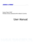
TM TM SIGNAL FORGE 1020 BATTERY POWERED SIGNAL GENERATOR User Manual … Technical Support Email: [email protected] Phone: 512.275.3733 Contact Information Web: www.signalforge.com Customer Service Email: [email protected] Phone: 512.275.3733 Fax: 512.275.3735 Address: Signal Forge, LLC ▪ 2115 Saratoga Drive ▪ Austin TX 78733 Table of Contents INTRODUCTION ----------------------------------- 6 Features -------------------------------------------- 6 Applications ---------------------------------------- 6 SPECIFICATIONS--------------------------------- 8 External Connector Pin Description--- 39 GENERAL SAFETY AND WARRANTY INFORMATION ----------------------------------- 41 To Avoid Fire or Personal Injury------------- 41 Warranty------------------------------------------- 41 CONNECTIONS-----------------------------------10 Front Panel Connections-----------------10 Rear Panel Connections -----------------11 SF1020E -------------------------------------------- 42 Clock Requirements ---------------------- 42 Reconfiguring SF1020E to SF1020--- 42 GETTING STARTED-----------------------------12 Battery----------------------------------------------12 Connecting the SF1020 to Your Computer12 Wave Manager Software ----------------------13 Creating a Waveform ---------------------14 Running the Waveform -------------------17 Saving Waveforms-------------------------17 Modifying Waveforms “On-The-Fly” --------17 Frequency Step Up, Step Down--------18 Power Level / Attenuation Control (dBm Base and Offset)-----------------------------------------18 POWER CONVERSION TABLES ----------- 44 OUTPUT TYPES ----------------------------------19 RF (AC Coupled) Output ----------------------19 Differential Output -------------------------------20 Digital Output -------------------------------------20 Operating Limits ---------------------------------20 Output Signal Frequency-----------------20 Waveform Modulation---------------------20 WAVEFORMS -------------------------------------23 ASK -------------------------------------------------23 BPSK -----------------------------------------------24 Chirp ------------------------------------------------25 Pulsed Chirp (Pulsed FM) ---------------------26 FSK Arbitrary Waveform-----------------------26 FSK Ramped -------------------------------------27 FSK Triangle--------------------------------------28 FSK Unramped-----------------------------------29 OOK-------------------------------------------------29 Single Tone ---------------------------------------30 Sine AM --------------------------------------------30 Square AM ----------------------------------------31 Sweep ----------------------------------------------32 ARBITRARY WAVEFORMS-------------------33 Arbitrary Modulation Operation --------------33 Waveform Descriptors--------------------------33 Digital Descriptors -------------------------------33 Floating Point Descriptors ---------------------33 Creating a Modulation File --------------------34 Sample File ----------------------------------34 Uploading A Modulation File------------------34 AUXILIARY UART--------------------------------36 CALIBRATION ------------------------------------37 EXTERNAL CONTROL CONNECTOR -----38 Recommended Cables/Connectors ---38 SOFTWARE UPDATE PROCEDURE ------ 46 EZ TERMINAL SOFTWARE ------------------ 47 PRODUCT LINE ---------------------------------- 49 Table of Figures Figure 1. Front Panel Figure 2. Rear Panel Figure 3. Wave Manager Main Menu Figure 4. Waveform Creation Menu Figure 5. Select New Waveform Menu Figure 6. Edit Parameters Menu Figure 7. Output Selection Menu Figure 8. Edit Parameters Menu Figure 9. Running New Waveform Figure 10. Modify Active Waveform Menu Figure 11. Modify Power Setting Figure 12. AC-Coupled Output Driver Figure 13. Differential Output Driver Figure 14. Digital Output Driver Figure 15. ASK Operation Figure 16. BPSK Operation Figure 17. Pulsed Chirp Operation Figure 18. Example FSK Arbitrary Waveform Figure 19. Sample - FSK Arbitrary Text File Figure 20. FSK Ramped Modulation Figure 21. FSK Triangle Modulation Figure 22. FSK Unramped Modulation Figure 23. Example - Sine AM Waveform Figure 24. Example - Square AM Waveform Figure 25. Sample - Arbitrary Modulation File Figure 26. Enable Arbitrary Waveform Option Figure 27. Upload Arbitrary Waveform File Figure 28: Auxiliary UART Usage Figure 29: External Control Header Pin Locations Figure 30: External Control Pin Filter Figure 31: FSK Control Pin Operation Figure 32: FSK Control Pin Operation Figure 33: SF1020 to SF1020E Jumper Positions Figure 34. Voltage Definitions 10 11 13 14 14 15 15 16 17 18 18 19 20 20 24 24 26 27 27 28 28 29 30 31 34 35 35 36 38 40 40 42 43 45 Table of Tables Table 1. Sine AM Samples per Cycle Table Table 3. Arbitrary Waveform: Max. Sample Rate Table 4. Digital Descriptor Definitions Table 5. External Control Header Pinout Table 6. Configuration Jumpers Table 7. RF Power Conversion Table 31 33 34 38 42 45 S F 1 0 2 0 U S E R M A N U A L Chapter 1 Introduction The Signal Forge 1020 Battery Powered Signal Generator is a portable, high performance signal source and function generator, with a frequency range of up to 1 GHz. Three dedicated outputs are provided along with support for numerous waveform modulation functions. Its small size and battery-powered operation make the Signal Forge 1020 (SF1020) ideal for a wide range of field test applications, from cable testing to the installation and maintenance of wireless networking and cellular phone systems, as well as testing and calibrating radio amplifiers and receivers. Features The Signal Forge 1020 supports the following features: Battery-powered operation 1 Hz to 1 GHz frequency range RF (AC-coupled), Digital and Differential outputs Sine wave AM, ASK, BPSK, CHIRP, FSK, OOK, SWEEP modulation modes Auxiliary UART allows user defined modulation data to be added to the carrier External and internal control of Start, ASK, BPSK, FSK, and OOK Signal stability of 1ppm and accuracy of 4ppm Wave Manager software pre-installed on SF1020 (no client software needed) Auto-run feature ideal for PC–free test operation Small, portable package (8.5in x 5.4in x 2.5in) , square wave Applications The SF1020’s portable size and wide frequency range are ideal for numerous field test applications such as: Installing and maintaining in-building wireless networks and cellular phone systems Digital output in sweep mode can be used to test setup and hold of digital systems—ICs and circuit boards—up to 110 MHz Differential output can used to test digital systems—ICs and circuit boards—up to 1 GHz Programmable clock generator Testing IF and RF sections of receivers as well as the mobile bands up to 1 GHz and some telemetry bands Test amplifiers for gain and for the 1 dB compression point Portable, bench top and ATE system applications 6 S F 1 0 2 0 U S E R M A N U A L Local Oscillator (L.O.) source Receiver calibration FSK and frequency sweep may be used to test FM receivers RF exciter Test low frequency filters (down to 1 Hz) BPSK may be used to test low data-rate applications such as IEEE 802.11g wireless LAN standard, RFID and Zigbee devices 7 S F 1 0 2 0 U S E R M A N U A L Chapter 2 Specifications Frequency Range RF (AC-coupled) Output…………………... 1 KHz – 1 GHz Digital Output……………………………….. 1 Hz - 110 MHz Differential Output………………………….. 50 MHz to 1 GHz Frequency Resolution................................................ 1 Hz Frequency Drift per hour (After warm-up)................. 0.0002 % Frequency Stability............................................... …. 0.001 % - Over temperature of range of 15-35 ºC ambient Frequency Accuracy.…………………………………4ppm (based on ± 2ppm TCXO) Frequency Stability……………………………………1ppm/year after the first year May drift 3ppm in the first year External Control Header Input Voltage……………………………….. 3.3V (5V Tolerant) Output voltage (TX_MOD pin)…………….. 5V Operating Voltage ……………………………………12V min to 15V max Operating Current………………………………….… 670mA Battery Life…………………………………………… 3 hours AC Adapter/ Charger (provided) …………………….Input 100-240VAC, 50/60 Hz. Output 24 VDC and 1.0A RF (AC Coupled) Output Amplitude Range……………………………………..143 mVp-p to 1414 mVp-p Amplitude Resolution................................................. 1 dB Power Range (RF Output)........................................ -12 dBm to +12 dBm Power Output Accuracy (RF Output)....................….±2 dB from 100 KHz to 300 MHz ±3 dB from 300MHz to 1 GHz Phase Noise ≤100 MHz -50 dBc/Hz @ 10 KHz Offset -73 dBc/Hz @ 100 KHz -90 dBc/Hz @ 1000 KHz 8 S F 1 0 2 0 U S E R Phase Noise M A N U A L >100 MHz -20 dBc/Hz @ 10 KHz Offset -60 dBc/Hz @ 100 KHz -90 dBc/Hz @ 1000 KHz Harmonics 2 MHz to 50 MHz............................< -40 dBc 50 MHz to 100 MHz.......................< -40 dBc 100 MHz to 3500 MHz....................< -20 dBc 300 MHZ to 500 MHz……………..<- 20dBc 500 MHz to 1GHz...........................< -20 dBc Non-Harmonics 100 KHz to 100 MHz...................... < -50 dBc 100 MHz to 500 MHz......................< -30 dBc 500 MHz to 1GHz….......................< -30 dBc Clock feed-through.....….............................................< -85 dBm Output Match (VSWR) 1 MHz to 7 MHz………..................< 1.5:1 @ +7 dBm output 7 MHz to 1 GHz….......................... < 1.3:1 @ +7dBm output Operating Temperature.....….................................... 0ºC to 40 ºC Note Output ratings at 100 MHz, 0 dBm output power and 25 ºC, unless otherwise specified Note For maximum stability, allow the SF1020 to warm up (soak) for 1 hour before use. 9 S F 1 0 2 0 U S E R M A N U A L Connections Front Panel Connections Figure 1. Front Panel Differential Outputs. Two SMA connectors for driving the differential clock output. LVPECL compatible, 50 MHz to 1 GHz. RF Output. One SMA connector for sourcing the AC coupled, unfiltered, sine wave output with a frequency range of 1 KHz to 1 GHz. The AC coupled output is capacitively connected to the output allowing the sine wave output to be floated at any level desired. Digital Output. BNC connector. Digital voltage levels supported are: TTL, LVTTL, STTL over a frequency range of 1 Hz to 110 MHz. On/Off LED. The front panel LED will be turned on solid if the SF1020 has powered up correctly. If the LED does not turn on, then a power error has occurred and the SF1020 may not be operational. Note: the LED is also turned off during some operations to signify a change of operational state Batt Low LED. When on, indicates that the battery needs to be recharged. To continue normal operation, AC power should be applied shortly after the Batt Low LED is illuminated. The AC adapter will charge the battery and operate the SF1020 simultaneously. Batt Fault. When on, indicates a defective battery. Contact Signal Forge technical support at [email protected] or 512-275-3733, option 2. Charging. When on, indicates that the battery is being charged. LED will turn off when charging is complete. Battery charge time when the SF1020 is off is approximately 90 minutes. The SF1020 may be operated while the battery is being charged. External Control. Dual-row 10-position header provides 10 two-pin connectors for: Frequency Shift Keying (FSK) control Binary (or Bipolar) Phase Shift Keying (BPSK) control Differential Clock On/Off Keying (OOK) control AC-coupled OOK control ASK control (RF output only) Remote START control 10 S F 1 0 2 0 U S E R M A N U A L The recommended connectors for the External Control are: - 20-pin connector and cable assembly. May be purchased from Signal Forge. See the Accessories section of the Signal Forge Product page at www.signalforge.com. - 2-pin connector housing and contacts for use if not all control signals are needed o 2-position housing p/n: A26921-ND o Contacts (2 required) p/n: A26951-ND - The connectors may be purchased from www.Digi-Key.com. Rear Panel Connections Figure 2. Rear Panel RS-232. The RS-232 port is a female DB-9 serial connector, which connects the SF1020 to the serial port on your PC. The required RS-232 port settings are: 8 data bits, 1 stop bit and no-parity; flow control: XON/XOFF only, no hardware handshake pins are implemented. The baud rate must be set to 57,600. Only the TX, RX and GND pins of the DB9 connector are implemented on the SF1020. RS-232 cables and USB to RS-232 serial adapters may be purchase from Signal Forge. 10 MHz Clock. BNC connector that provides a 10 MHz TTL reference output signal derived from the internal TCXO timebase. Output impedance is approximately 50 Ω. The accuracy of the 10 MHz output is 0.83 ppm. This square wave clock output has 70/30 symmetry Note The rear BNC connector for the 10 MHz clock is a reference clock input on the SF1020E enabling it to be driven by an external standard. It is a clock output on the SF1020. Power. Input for the AC adapter-battery charger (provided). The AC adapter/charger provides 24VDC and 1.0A output; Input range 100-260V, 50/60 Hz. The adapter provides operating power and simultaneously charges the battery On/Off. Power on/off button. The LED on the front panel will be on solid if the SF1020 has powered up correctly. If the LED does not turn on, then a power error has occurred and the SF1020 may not be operational. In this case contact technical support for assistance. 11 S F 1 0 2 0 U S E R M A N U A L Chapter 3 Getting Started Note Before you use the SF1020 for the first time, the battery MUST be charged. (The SF1020 is shipped from the factory in a sleep state that requires a connection to the charger to wake it up.) Battery The SF1020 is equipped with a Nickel-Metal Hydride battery pack which provides approximately 3 hour of continuous operation. The battery must be charged prior using the SF1020 for the first time. Charging takes approximately 90 minutes. The SF1020 may be operated while the battery is charging. When the battery needs to be recharged, the Batt Low LED on the front of the SF1020 will illuminate. If the AC adapter/charger is not plugged in shortly after the LED turns on, the SF1020 will automatically turn off the output signal. Connecting the SF1020 to Your Computer 1. Connect your PC to the serial port on the SF1020 Serial Port: Attach a standard serial port cable with a male DB-9 connector and straight through pin out to the RS232 port on the rear panel of the SF1020 and the other end to the serial port on your computer. Standard serial cables may be purchased many sources including Signal Forge. USB: To connect your computer to the SF1020 via USB connection, use an inline serial port to USB adapter. A USB to serial adapter is available from the Signal Forge web site, www.signalforge.com. 2. Start your terminal communication software -- such as the Signal Forge EZ Terminal or HyperTerminal. Start EZ Terminal (Vista, XP, W2K) HyperTerminal (XP, W2K), XTerm (Linux) or other serial communication software and configure it as follows: 8 data bits, 1 stop bit, no-parity, flow control: XON/XOFF, baud rate must be set to 57,600 3. Access Wave Manager User Interface: Once the serial cable is connected and the serial communication software started and configured, turn on the SF1020 and the Wave Manager user interface will load. Wave Manager software is installed on the SF1020 so you do NOT need to install any special software on your PC. Note If EZ Terminal or HyperTerminal is started after the SF1020 has been turned on, press ESC to refresh the Wave Manager user interface.. 12 S F 1 0 2 0 U S E R M A N U A L Note EZ Terminal may be downloaded for free from Accessories section of the Signal Forge Products page at www.signalforge.com. Wave Manager Software Setup, configuration and programming is accomplished using Wave Manager, the menu-driven software which comes pre-installed on the SF1020. No client-side software is required. Standard serial terminal communication software on your PC is all that is required to load the Wave Manager software. Simply connect a serial cable between your PC and the SF1020, start the terminal communication software (i.e. EZ Terminal), turn on the SF1020 and Wave Manager loads automatically. At power up, the main menu is displayed, presenting the current configuration, operational status and programming options. The menu screens are organized such that only the options allowable for the selected waveform and output type are displayed making the software easy to learn and navigate. Figure 3. Wave Manager Main Menu 13 S F 1 0 2 0 U S E R M A N U A L Creating a Waveform To configure a new waveform, select the Waveform Creation Menu. Figure 4. Waveform Creation Menu First select New Waveform Type and choose the desired waveform from the list. Figure 5. Select New Waveform Menu 14 S F 1 0 2 0 U S E R M A N U A L Hit ESC to return to the main Waveform Creation Menu, then select Edit Parameters. Figure 6. Edit Parameters Menu Then select Output from the menu to configure the output type from the list displayed. Figure 7. Output Selection Menu 15 S F 1 0 2 0 U S E R M A N U A L Figure 8. Edit Parameters Menu Hit ESC to return to the main Edit Parameters menu and configure all other applicable parameters such as frequency, output power, etc. External Controls. The Edit Parameters menu also allows you to enable the external controls, where applicable. See the External Controls section for a description of the external control connector. Note The Arbitrary Modulation selection enables you to upload a file containing a user defined modulation pattern. See the Arbitrary Modulations and Arbitrary Waveforms chapter below for information on creating an Arbitrary Modulation file. Note Entering a frequency value greater than the maximum supported will be flagged as an error or automatically reset to the highest valid value. 16 S F 1 0 2 0 U S E R M A N U A L Figure 9. Running New Waveform Running the Waveform Return to the main Waveform Creation menu and select Run to start the new waveform. You may run the waveform with or without saving it. Saving Waveforms From the Waveform Creation menu, you may chose to save the new waveform to one of the four non-volatile memory locations. You also have the option to save your waveform with the Load at Power-up option. The Load at Power Up feature causes the selected waveform to be loaded and started when the SF1020 is first turned on. This feature enables the SF1020 to operate in a repeatable stand-alone mode. Note Saving a new configuration overwrites any previously saved configuration at that location. In addition to the four memory locations, one set of user-developed arbitrary waveform data may be saved (see the Arbitrary Waveform Modulation section below). Modifying Waveforms “On-The-Fly” Some of the parameters of the Single Tone and FSK type waveforms may be modified during runtime providing you with increased flexibility to exercise specific areas of the device under test. 17 S F 1 0 2 0 U S E R M A N U A L Figure 10. Modify Active Waveform Menu Frequency Step Up, Step Down While either the Single Tone or FSK type waveform is running, the frequency may be changed by stepping it up or down in discrete steps using the selections on the Modify Active Waveform menu (in the case of FSK, Frequency 1 is changed only). The frequency may be repeatedly stepped up or down in increments of 1 Hz, 10 Hz or 100 Hz. You may also enter a new frequency value by using menu selection [F]. Power Level / Attenuation Control (dBm Base and Offset) The Wave Manager software allows you to change the Base power level and the Offset during operation when the AC Coupled output is enabled. The power values are entered in dBm. Base Power (dBm Base). Base power may be increased or decreased within the supported range, which is 12 dBm to +12 dBm. Offset. Allows you to adjust the Base Power to offset the losses of external connections (i.e. interconnect cables). For example: You enter a frequency of 500 MHz and require an output of 5 dBm; you then enter an offset of 2 dB causing the SF1020 to drive the output at 7dBm. After a cable loss of 2 dBm, the output power measured at the Device Under Test should be 5 dBm (7-2 = 5 dBm) In all cases; the total power must not exceed the maximum dBm provided by the SF1020. Figure 11. Modify Power Setting 18 S F 1 0 2 0 U S E R M A N U A L Chapter 4 Output Types The SF1020 provides three different output types: RF (AC Coupled) Differential Digital All outputs have a resolution of 1Hz. When an output type is selected, all other output types are automatically disabled (e.g. when AC Coupled is selected, the TTL output is tri-stated and the differential output is at 0 MHz). RF (AC Coupled) Output The output driver of the RF (AC Coupled) signal source provides a nominal 50-Ohm output impedance–the output driver implementation is described in the drawing below. AC coupled output is capacitively connected to the output allowing the sine wave output to be floated at any level desired. 50 ohms trace SMA CONNECTOR .1uF MMIC SF1020 Figure 12. AC-Coupled Output Driver 19 S F 1 0 2 0 U S E R M A N U A L Differential Output The outputs of the differential driver conform to the LVPECL standard. The driver and the recommended method of interfacing to it are described in the drawing below. This differential driver is designed to work in 50-Ohm systems. The rise and fall times for the differential outputs are: 175ps (min) to 425ps (max) - 20% to 80% measure with a 50ohm load. SMA -P 50 Ohms Receiver Device SMA -N 50 Ohms SF1020 VTT = 1.3V Figure 13. Differential Output Driver Digital Output The following block diagram shows the implementation of the programmable TTL output buffer. The rise and fall times for the rise and fall times for the digital output are: 1.2ns (0.7V to 2.0V) max. Enable BNC IOH = 12mA IOL = 12mA Vout Control 1.8V, 2.5V, 3.3V 22 Ohms Figure 14. Digital Output Driver Operating Limits Output Signal Frequency RF output 1 KHz to 1 GHz Differential output 50 MHz to 1 GHz Digital output 1 Hz - 110 MHz Waveform Modulation ASK - Internally Controlled RF Digital Differential Output Frequency 1 KHz to 1 GHz not supported not supported Modulating Frequency 1 Hz to 500 KHz 20 S F 1 0 2 0 U S E R ASK - Externally Controlled RF Digital Differential Output Frequency 1 KHz to 1 GHz not supported not supported Modulating Frequency 1 Hz to 150 KHz Output Frequency 1 KHz to 100 MHz not supported not supported Modulating Frequency 0.1 Hz to 500 KHz BPSK RF Digital Differential M A N U A L CHIRP RF Digital Differential Output Frequency 1 Hz to 110 MHz 1 Hz to 110 MHz 50 MHz to 1 GHz CHIRP operates over the entire range of each supported output type. FSK Ramped and Unramped - Internally Controlled RF RF Digital Differential o Output Frequency ≤100 MHz >100 MHz 1 Hz to 110 MHz 50 MHz to 1 GHz Duty cycle (Frequency1 direction) Modulating Frequency 0.1 Hz to 500 KHz 0.1 Hz to 500 KHz 0.1 Hz to 500 KHz 0.1 Hz to 500 KHz 10% to 90% FSK Ramped and Unramped - Externally Controlled RF RF Digital Differential Output Frequency ≤100 MHz >100 MHz 1 Hz to 110 MHz 50 MHz to 1 GHz Modulating Frequency 0.1 Hz to 150 KHz 0.1 Hz to 150 KHz 0.1 Hz to 150 KHz 0.1 Hz to 150 KHz For RF frequencies >100 MHz and all Differential frequencies, FSK operates within the following bands: 100-200 MHz, 200-400 MHz, 400-800 MHz, 800 MHz-1 GHz FSK Arbitrary RF RF Digital Differential Output Frequency ≤100 MHz >100 MHz 1 Hz to 110 MHz 50 MHz to 1 GHz Modulating Frequency 0.1 Hz to 26 KHz 0.1 Hz to 26 KHz 0.1 Hz to 26 KHz 0.1 Hz to 26 KHz For RF frequencies >100 MHz and all Differential frequencies, FSK operates within the following bands: 100200 MHz, 200-400 MHz, 400-800 MHz, 800 MHz-1 GHz OOK - Internally Controlled RF Digital Differential Output Frequency 1 KHz to 100 MHz not supported 50 MHz to 1 GHz Modulating Frequency 0.1 Hz to 500 KHz 0.1 Hz to 500 KHz 21 S F 1 0 2 0 o U S E R The duty cycle (ON percentage) o Modulating Frequency 0.1 Hz to 150 KHz 0.1 Hz to 150 KHz 10 to 90% except near the highest modulating frequency Sine AM Output Frequency 1 KHz to 1 GHz not supported not supported Modulating Frequency 0.1 Hz to 65 Hz Output Frequency 1 KHz to 1 GHz not supported not supported Modulating Frequency 0.1 Hz to 45 KHz Square AM RF Digital Differential Output Frequency 1 KHz to 100 MHz not supported 50 MHz to 1 GHz The duty cycle (ON percentage) RF Digital Differential 10 to 90% except near the highest modulating frequency OOK - Externally Controlled RF Digital Differential M A N U A L Sweep RF Digital Differential Output Frequency 1 KHz to 1 GHz 1 Hz to 110 MHz 50 MHz to 1 GHz Sweep operates over the entire range of each supported output type. o Frequency sweep time Minimum step time for frequencies ≤100 MHz = 5ms Minimum step time for frequencies >100 MHz = 10ms Step time programmable in 5ms and 10ms increments, respectively Maximum step time = 60 seconds. 22 S F 1 0 2 0 U S E R M A N U A L Chapter 5 Waveforms The SF1020 provides a wide range of waveform modulation functions from which you can create a variety of waveforms. Numerous waveform modifiers may be applied to customize the output to meet your specific testing needs. The waveforms, modifiers and options are configured using the Wave Manager software. In addition, you may develop arbitrary modulation files to create your own unique type of FSK or AM modulated output. An Arbitrary Modulation option will be displayed on the Edit Parameters screen of any waveform that supports user-developed waveform modulation files. ASK Outputs Supported RF Options Internal control External control Amplitude-shift keying (ASK) is a form of modulation that represents digital data as variations in the amplitude of a carrier wave. The amplitude of an analog carrier signal varies in accordance with the bit stream (modulating signal), keeping frequency and phase constant. The amplitude level can be used to represent binary logic 0s and 1s. The carrier signal is switched ON or OFF and the modulated signal, logic 0 is represented by the absence of a carrier, thus giving the OFF/ON keying operation. The ASK operation of the SF1020 varies the output power (amplitude) between two user-selected settings. ASK may be controlled internally by the Wave Manager software or by an external controller. For internally controlled ASK, the supported frequency range 1 Hz to 200 KHz. For externally controlled ASK, the supported frequency range is 1 Hz to 1000 KHz (see drawing below). The ASK control pin on the External Control connector block on the front panel is used as an arbitrary modulation source to control the output carrier. ASK Operation Using the Wave Manager software, select the high power value from the supported range. The supported range is calculated using an internal output-power range table and varies depending on the frequency selected. Use the Wave Manager software to determine the supported range at a given frequency. However, 7 dBm is supported for all frequencies and is the recommended setting for ASK operation. If lower power output is needed, an external attenuator, such as the Mini-Circuits Inline BW-SXW2 Series Precision Fixed Attenuator is recommended. The low power value is automatically set to 16dB below the high power value (i.e 5dBm – 16dB = -13dBm). External ASK Operation To control ASK externally using the External Control header on the front panel. 23 S F 1 0 2 0 U S E R M A N U A L Use the Wave Manager software, set ASK control to ENABLED. Connect your ASK controller to the top pin at position 7 of the External Control header. The bottom pin of location 7 should be left open. Use the top pin at location 6 for a GND return connection. The input control signal must be 3.3V to 5V (the SF800/1000 input is 5V tolerant) Proper filtering be applied to the ASK control pin to avoid excessive overshoot or undershoot (due to long traces for example) The drawing below illustrates ASK operation: Carrier Amplitude External Control Signal Figure 15. ASK Operation BPSK The BPSK (binary or bipolar phase shift keying) waveform outputs a single frequency that quickly changes between two user-selected phase offsets. When the phase selection changes to phase 1, the phase jumps by phase 1. When the phase selection changes to phase 2, the phase jumps by phase 2. BPSK is a form of PSK which uses two phases separated by 180° and is sometimes called 2-PSK. It modulates at 1bit/symbol and is used for testing low data-rate applications such as IEEE 802.11g wireless LAN standard. BPSK is also suitable for testing low-cost passive transmitters such as those used in the RFID standards which have been adopted for biometric passports, credit cards and other applications. Due to synchronization the phase changes are not instantaneous, but the user can inspect the timing and adjust the phase values if compensation is desired. 360 PHASE PHASE SHIFT 0 TIME Figure 16. BPSK Operation 24 S F 1 0 2 0 U S E R M A N U A L Outputs Supported RF to 100 MHz Options Internally controlled Externally controlled BPSK (same pin as FSK) – low selects Phase 1 Externally controlled Start Arbitrary modulation (from a user created file) Chirp Outputs Supported RF Differential Digital (TTL) Options Externally controlled Start The Chirp waveform ramps the output from frequency 1 to frequency 2 over a specified time, then jumps to the starting frequency to begin the next chirp. A rising or falling chirp is allowed. The pulse width menu entry specifies the duration of the chirp. The Wave Manager software automatically calculates the delta frequency and ramp rate for the chirp using frequency steps of up to 50 KHz (based on the pulse width and frequency range). Chirp Operation for Frequencies ≤100 MHz When using the digital or the RF (AC coupled) outputs with a frequency setting of 100 MHz or less, chirp can be configured to immediately jump from F2 (frequency 2) to F1 (frequency 1) at the end of the chirp ramp. Chirp Operation for Frequencies Above 100 MHz When using the differential output (any frequency) or the RF output at a frequency setting above 100 MHz, the chirp frequency ramps to F1 instead of jumping to F1. Some frequencies are lost close to F1 due to internal hardware limitations.. The amount of lost frequency depends on the rate of change from F1 to F2, the frequency difference between F1 and F2, and the internal lock time. It is possible to account for lost frequencies near F1 by entering a slightly lower F1 value for a rising chirp or higher F1 value for a falling chirp. It is left up to the user to manually compensate for lost frequencies. As an example of compensating for lost frequencies, assume your SF1020 locks in 500us and you want to chirp 300 MHz to 400 MHz in 4ms. This puts you in the operating range of 200-400 MHz. Since you are doing ½ the possible frequency range, you would expect the lock time in this example to be 250us. You need to lower F1 by a value that will represent 250us. Step 1: ramp rate is 300-400 MHz in 4ms = 100 MHz/4ms = 25 MHz/ms = 25 KHz/us Step 2: 25 KHz/us * 250us lock time = 6.25 MHz so you need to subtract 6.25 MHz from F1 (menu entry F1 = 293.75 MHz). Of course, the most accurate method is to use a spectrum analyzer to change F1 until the desired range is seen. 25 S F 1 0 2 0 U S E R M A N U A L Pulsed Chirp (Pulsed FM) The pulsed-chirp (sometimes referred to as pulsed FM) waveform ramps the output from frequency 1 to frequency 2 over a specified time, jumps to the starting frequency, then idles at frequency 1 until the next chirp. A rising or falling chirp is allowed. The pulsed-chirp width menu entry specifies the duration of the chirp (frequency 1 to frequency 2). The pulse-topulse time menu entry specifies the time between chirps. The Wave Manager software automatically calculates the delta frequency and ramp rate for the chirp, using up to 50 KHz frequency steps (based on the pulse width and frequency range). “Idle time” (the amount of time at frequency 1 between chirps) can be calculated as <pulse-topulse> minus <chirp pulse width>. When using the digital output, or the RF (AC coupled) output at a frequency rate of 100 MHz or less, there is an option to idle at 0 Hz instead of frequency 1. F2 Frequency F1 TIME Figure 17. Pulsed Chirp Operation Outputs Supported RF Differential Digital (TTL) Options Externally controlled Start Pulsed Chirp Operation for High Frequencies As described in the chirp waveform section, when using the differential output at any frequency or the RF output at a frequency above 100 MHz, the chirp cannot jump immediately back to frequency F1. There will instead be a ramp back to F1. Since there is an idle time at F1, then F1 will be reached so no frequencies are lost. FSK Arbitrary Waveform For Frequency Shift Keying (FSK) Arbitrary Waveforms, a user developed file describing a set of frequency variations is uploaded to the SF1020 and optionally saved in internal non-volatile memory. One arbitrary data set may be saved at a time. FSK Arbitrary descriptor files may be created using a text editor or waveform generator software. Arbitrary FSK allows the user to specify a set of frequency variations, the user-entered data includes: Center frequency Modulating frequency 26 S F 1 0 2 0 U S E R M A N U A L Sample rate (range is 0.1 Hz to 26 KHz) A set of descriptors that define the deviation for each sample point The output frequency changes at a time defined by the sample rate. The actual output frequency is determined using the formula Fout = <center frequency > + (deviation * descriptor) Where each descriptor is a floating point value in the range –1.0 to 1.0. For example, a center frequency of 50 MHz with deviation 10 MHz and descriptor -0.5 will create a frequency of 45 MHz. The file format and number of descriptors supported is described in the Creating Arbitrary Waveforms chapter below. The drawing below illustrates how FSK Arbitrary Waveforms operate. Frequency TIME F1 0 +.5 0 -1 +.25 +.25 +1 Figure 18. Example FSK Arbitrary Waveform The FSK waveform shown above was created from the following text file: number_of_points 7 // start with highest output frequency for 1 sample times 1.0 //go down to center frequency and then back to highest using 25% freq X 2 .50 0 -.10 .25 .25 1.0 Figure 19. Sample - FSK Arbitrary Text File FSK Ramped The FSK Ramped waveform varies the output frequency within a specified range. The rate of frequency change is determined by the delta frequency (the amount that the frequency is changed at each step) and the ramp rate (at what interval the frequency is changed). The direction of frequency change is determined by internal timers or by the front panel FSK signal (when external control is enabled). For internal FSK operation, the modulating frequency and duty cycle determine how long frequency1 and frequency2 are selected. When frequency2 is selected, the direction of change is towards frequency2. Once frequency2 is reached, the frequency will remain there until the internal timer signal selects frequency1 (which causes the frequency to ramp towards frequency1). The user would normally select a modulating frequency and duty cycle such that the ramp has time to complete (i.e. If the FSK signal changes before the ramp is complete, then you will not have reached full range). See drawing below: 27 S F 1 0 2 0 U S E R M A N U A L Modulating Frequency Frequency 2 F Ramp Rate & Delta Freq. Frequency 1 TIME Figure 20. FSK Ramped Modulation Outputs Supported RF Differential Digital (TTL: 3.3V, LVTTL: 2.5V, SVTTL: 1.8V) Options Externally controlled OOK Externally controlled Start Arbitrary modulation (from a user created file) FSK Triangle FSK Triangle is similar to FSK ramped, except that ramping from one frequency to the next occurs automatically. When an end frequency is reached, the direction changes and ramping continues towards the other frequency. See drawing below: Frequency 2 F Ramp Rate & Delta Freq. Frequency 1 TIME Figure 21. FSK Triangle Modulation Outputs Supported RF Differential Digital (TTL: 3.3V, LVTTL: 2.5V, SVTTL: 1.8V) 28 S F 1 0 2 0 U S E R M A N U A L Options Externally controlled OOK Externally controlled Start FSK Unramped The Frequency Shift Keying (FSK) Unramped waveform allows you to select two output frequencies which are alternately driven at a preprogrammed rate. For internal FSK operation, the modulating frequency that determines the rate at which the frequencies change is selected from the Edit Parameters menu. The duty cycle menu entry determines the duration that frequency1 is asserted versus frequency2. The alternate frequency selection is determined either by internal timers, or by the front panel FSK signal (when external control is enabled). Modulating Frequency Frequency 2 F Frequency 1 Start TIME Figure 22. FSK Unramped Modulation Outputs Supported RF Differential Digital (TTL: 3.3V, LVTTL: 2.5V, SVTTL: 1.8V) Options Externally controlled OOK Externally controlled Start Arbitrary modulation (from a user created file) OOK On-off keying (OOK) is a modulation scheme which consists of keying a carrier signal on and off with a unipolar binary signal. OOK is equivalent to 2-level Amplitude Shift Keying (ASK). On-off keying (OOK) modulation that digital data as the presence or absence of a carrier wave. The presence of a carrier for a specific duration represents a binary one, while its absence for the same duration represents a binary zero. OOK may be been used to transfer data using RF carrier waves. It is also used in optical communication systems such as infared data transfer interfaces (e.g. IrDA). In aviation, some airports have equipment that let pilots key their VHF radio a number of times in order to request an Automatic Terminal Information Service broadcast, or turn on runway lights. 29 S F 1 0 2 0 U S E R M A N U A L Outputs Supported RF Differential Single Tone The Single Tone waveform outputs a continuous tone at the user-selected output frequency. Outputs Supported RF Differential Digital (TTL: 3.3V, LVTTL: 2.5V, SVTTL: 1.8V) Options Externally or internally controlled OOK Externally controlled Start Note External control requires an external user-provided modulating source (TTL level). Sine AM A Sine Wave AM waveform modulates power using a sinusoidal pattern. The SF1020 outputs a discrete number of power levels as shown in the drawing below. The existence of these discrete power steps is normally not an issue since an AM demodulator includes a low pass filter at its output that will remove any high frequency components (higher than the maximum modulating frequency). Modulating Frequency (Sine Wave Approximation) Carrier Frequency Base Power (Enter in dBm) Opposite Envelope Power (in dBm) Figure 23. Example - Sine AM Waveform Outputs Supported RF Options Externally controlled OOK Externally controlled Start Arbitrary modulation (from a user created file) 30 S F 1 0 2 0 U S E R M A N U A L The modulating frequency affects the number of sample points that are used to create the waveform as shown in the following table: Modulating frequency Samples per cycle 7500 Hz 12 2500 Hz 36 1500 Hz 60 750 Hz 120 500 Hz 180 250 Hz 360 Table 1. Sine AM Samples per Cycle Table The Arbitrary Modulation mode may be used to completely customize an AM waveform by downloading a usergenerated arbitrary descriptor file. In this case, each descriptor defines the output power using values of –1.0 to 1.0, where –1.0 is the lowest power and +1.0 is the highest power. Note Maximum Square AM modulating frequency is 40 KHz. Maximum Sine AM modulating Frequency is 6.5 KHz. Square AM For Square AM, the user specifies a single frequency (the carrier frequency) and two power values. The duty cycle may be programmed to a value other than 50%, which will result in the creation of an asymmetrical wave instead of a square wave (50% at the first power value and 50% at the lower power value). The drawing below depicts AM Square Wave operation (in this example, the modulation is set to 50%) Modulating Frequency (Square Wave) Base Power (Enter in dBm) Alternate Envelope Power (in dBm) Figure 24. Example - Square AM Waveform Arbitrary waveform modulation may be used to completely customize an AM type waveform by downloading arbitrary amplitude descriptors from a user-generated file. Outputs Supported RF 31 S F 1 0 2 0 U S E R M A N U A L Options Externally controlled OOK Externally controlled Start Arbitrary modulation (from a user created file) Sweep Sweep is similar to the FSK ramped mode of operation except that it allows frequencies to span the full operational range. It also allows any delta frequency. Sweep allows the user to pause, change direction, or single-step. When a sweep range completes, it starts over at the first frequency. The SF1020 sweep step size (and minimum sweep rate) is 5ms for frequencies ≤100 MHz and 10ms for frequencies greater than 100 MHz Outputs Supported RF Differential Digital (TTL: 3.3V, LVTTL: 2.5V, SVTTL: 1.8V) Options Externally controlled or OOK Externally controlled Start 32 S F 1 0 2 0 U S E R M A N U A L Chapter 6 Arbitrary Waveforms Arbitrary Waveforms allow the user to define specific frequency or power values at a specified sample rate. CHIRP testing can be executed easily with the SF1020 by creating the appropriate arbitrary waveforms. The following sections describe how to create, upload and save Arbitrary Modulation files to the SF1020. An Arbitrary Modulation selection will be displayed on the Edit Parameters menu of all waveforms that support arbitrary modulation. Arbitrary Modulation Operation The Arbitrary Modulation mode of operation enables you to specify data points that describe a waveform and the rate of execution. The maximum rates are shown in the following table. Operation Sample Rate OOK 90 KHz FSK / BPSK 90 KHz Square AM 80 KHz Sine AM 80 KHz Table 2. Arbitrary Waveform: Max. Sample Rate Waveform Descriptors Two types of descriptors are supported: digital and floating point. Digital Descriptors Digital descriptors are used in cases where the output is only in one of two states, such as on/off or frequency high/low. Up to 2048 digital descriptors are supported. For example, digital descriptors would be used for OOK operation or Square Wave AM. Digital descriptors may be in floating point or integer format where values greater than 0 are considered TRUE and other values are considered FALSE. Floating Point Descriptors Floating-point descriptors are used in cases, such as FSK Arbitrary or Sine AM, where the output is in more than two states. Up to 512 floating point descriptors are supported. Floating point descriptors must be in the range –1.0 to 1.0, and are used to define the amount of deviation to apply at each sample point. The output is determined by multiplying the descriptor and deviation, then adding the result to the center value. 33 S F 1 0 2 0 U S E R M A N U A L Creating a Modulation File An Arbitrary Modulation file must comply with the following criteria. The file may be created using a text editor, or any program that creates an ASCII file: One line should contain the keyword “number_of_points “ followed by the number of sample points described (e.g. “number_of_points 22”). This may be on any line. Sample points separated by spaces, commas, or tabs Comments may be inserted anywhere in the file starting with any character other than characters used for numbers (“0123456789.+-“), or matching the keyword “number_of_points”. When a comment character is recognized, the rest of the line is ignored. The file must contain, at a minimum, the number of sample points indicated on the “number_of_points” line. If you include more samples than specified, they will be ignored. Digital Descriptors Operation Description OOK FALSE means output is OFF, else ON FSK FALSE means output frequency one, else frequency two AM square wave FALSE means output low power, else high power BPSK FALSE selects phase 1, else phase 2 Table 3. Digital Descriptor Definitions The following sample file describes how to create a floating point set of data points to control an FSK type or AM sine wave type of output: Sample File // file sine.txt // Half Sine wave data points for FSK arbitrary or Sine AM number_of_points 15 -1.0 -.8 -.6 -.4 -.3 -.2 -.1 0 .1 .2 .3 .4 .6 .8 1.0 Figure 25. Sample - Arbitrary Modulation File Uploading A Modulation File Once created, the Arbitrary Modulation file may be uploaded to the SF1020 and optionally saved in its non-volatile memory. Before uploading the file, you must first setup the waveform that will be modulated by your set of arbitrary data points. There are two ways to setup the waveform: Select either the FSK Arbitrary waveform from the New Waveform Type menu ENABLE Arbitrary Waveform from the Edit Parameters menu (where applicable). Once enabled, an Upload Arbitrary Modulation File selection will appear on the Edit Parameters menu. 34 S F 1 0 2 0 U S E R M A N U A L Figure 26. Enable Arbitrary Waveform Option Next select Upload Arbitrary Waveform File and follow the onscreen instructions. Figure 27. Upload Arbitrary Waveform File Note If you wish to save the arbitrary data to non-volatile memory, use the save option before exiting the arbitrary modulation menu. 35 S F 1 0 2 0 U S E R M A N U A L Chapter 7 Auxiliary UART The SF1020 provides a transmit-only UART port (TX_MOD – pin 8) that may be used to send ASCII data characters to an internal or external modulation device. This port is completely separate from the UART port used for the console. This port is ideal for injecting custom modulation data into the carrier wave generated by the SF1020. The data that is sent by the auxiliary UART port can be ASCII data generated by a keyboard or from a file. The baud rate is programmable at these rates: 2400, 4800, 9600, 19200, 38400, and 57600 baud (SF1020 HW version C also supports 150, 300, 600, and 1200). The Wave Manager software provides support for this UART port on the Auxiliary UART Menu (under the Modify Active Menu entry). You may connect the Auxiliary UART output using the appropriate filtering/interface (i.e. polarity control) to an external modulating device or to the OOK/FSK control pins of the same SF1020. In this way, you can create modulated waveform outputs, which are actually encoding UART driven data. The diagram below depicts how to configure the UART TX_MOD pin to create an ASCII data keyed OOK Waveform: AC Coupled (Output) SF1000 OOK Pin (Input) External Control Header Optional External Filtering or Control TX_MOD pin (Output) Figure 28. Auxiliary UART Usage 36 S F 1 0 2 0 U S E R M A N U A L Chapter 8 Calibration Calibration Interval The signal generator should be checked 1 year intervals to determine if the carrier frequency needs to be calibrated. Be aware that modulation depth, modulation frequency and output level are not adjustable. The output level may be adjusted using external amplifiers or attenuators. Procedure Calibration should take place in an environment in which the temperature is the same as the temperature at which the unit will be used. Note If you have an “E” model, either attach an external clock source or reconfigure it so that the internal clock source is enabled. 1. Power up the SF1020 for 1 hour prior to calibration to allow for temperature soak. 2. Connect the SF1020 to an accurate frequency counter. 3. Use the Wave Manager software to select the TTL or the AC-coupled output 4. Set the frequency to 1 MHz, 10 MHz or 100 MHz. 10 MHz is used at the factory for initial calibration. 5. Select "Calibration" from the Main Menu. 6. Enter the frequency displayed on the external frequency counter into the space provided on the calibration menu. The difference between frequency counter reading and the frequency setting is used to calibrate the device. The calibration information is stored in non-volatile memory, loaded at power up, and used until the device is calibrated again. 37 S F 1 0 2 0 U S E R M A N U A L Chapter 9 External Control Connector The SF1020 provides ten 2-pin connectors labeled External Control on the front panel. These connectors enable you to control several modulation functions, such as frequency shift keying (FSK) or On/Off Keying (OOK). The function assignments are listed below. POSITION NAME (bottom row) POSITION NAME (top row) 1 Reserved 1 Reserved 2 DIFF OOK 2 GND 3 FSK / BPSK 3 GND 4 TX_MOD 4 GND 5 SE OOK 5 GND 6 Reserved 6 GND 7 15V 7 ASK 8 15V 8 GND 9 START 9 GND 10 Reserved 10 GND Table 4. External Control Header Pinout SF1020 10 9 8 7 6 5 4 3 2 1 Top Row Bottom Row External Control Figure 29. External Control Header Pin Locations Recommended Cables/Connectors You may attach either a 20-pin connector and cable assembly to a entire External Control block or individual 2-pin assemblies to control a single function. The recommended connector are: - 20-pin connector and cable assembly P/N: M3AAA-2006J-ND 38 S F 1 0 2 0 U S E R M A N U A L - 2-pin connector housing and contacts may be used to connect to individual control positions o 2-position housing P/N: A26921-ND o Contacts (2 required) P/N: A26951-ND The connectors and cables may be purchased from www.Digi-Key.com. External Connector Pin Description DIFF OOK. The differential clock output supports OOK for the frequency range of 50 MHz to 1 GHz. This input pin controls the differential output: driving this pin low will stop the differential output. By default this pin is set to a high state. FSK / BPSK. For FSK waveforms, this pin allows the user to shift the frequency output as defined previously. For BPSK waveforms, this pin selects between phase 1 and phase 2 and as defined previously. TX_MOD. This is the TX output from the internal Auxiliary UART port. The Wave Manager software provides support for this UART port on the Auxiliary UART Menu (under the Modify Active Menu entry). The user can connect this output, using the appropriate filtering/interface to the OOK or FSK external control pins of the SF1020 and create UART data modulated waveforms if so desired. SE OOK. The SF1020 supports OOK (On/Off Keying) for the AC Coupled output in frequency range of 100 KHz to 100 MHz only. This input pin provides for external control of the output: placing this pin low stops the output of the SF1020. This pin is normally set to a high state. ASK. This control pin allows you to modulate the AC Coupled output in order to implement an externally controlled Asynchronous Shift Keying. When this pin is driven low the AC coupled output will be attenuated by 16 dB over the full output power (when the signal is high). Note: The ASK control pin is the only control pin that does not have a GND pin as its opposite, Any other GND pin on the External Control connector may be used instead. START. External START is an output control option. A high to low transition causes the SF1020 to start outputting its preprogrammed frequency. This feature is available for the AC Coupled, Differential and TTL outputs. When waiting for START the front panel LED is OFF until a valid START polarity is received. FSK unramped or triangle waveforms with external FSK control do not support the wait for START (output is as selected by the FSK external control pin). The time from assertion of the START signal to output valid will vary depending on the type of output/frequency chosen and modifiers used. The user must first measure this time delay and account for it - if it will affect the type of operation being performed. As described above, the SF1020 gives you the ability to control the output frequency using external control pins. Each one of the control pins has a low pass filter placed at its input, except for the Start pin. The low pass filter has a 3 dB cutoff point of 150 KHz. The input signals must be driven by 3.3V compatible signals and be referenced to the SF1020 GND (any of the GND pins of the 20-pin header). Input impedance is 2K ohms. 39 S F 1 0 2 0 U S E R M A N U A L The External Control inputs are 5V tolerant and include a certain level of protection as described in the following block diagram: 3.3V Input LPF Diode Protection Figure 30. External Control Pin Filter The Figure below gives an example of external control of a waveform. In the example chosen, an external signal controls the FSK signal pin of the SF1020. FSK Pin Frequency 2 F Frequency 1 Start TIME Figure 31. FSK Control Pin Operation 40 S F 1 0 2 0 U S E R M A N U A L Chapter 10 General Safety and Warranty Information Review the following safety precautions to avoid injury and prevent damage to this product or any products connected to it. To avoid potential hazards, use this product only as specified. Only qualified service personnel should perform service procedures. To Avoid Fire or Personal Injury Use Proper Power Adapter. Use only the power module provided with this product. Connect and Disconnect Properly. Do not connect or disconnect external header pin leads while they are connected to a voltage source (turn the SF1020 and external control logic simultaneously). Observe All Terminal Ratings. Consult the product manual for ratings information before making connections to the product. Do Not Operate Without Cover. Do not operate this product with the cover removed. Do Not Operate With Suspected Failures. If you suspect there is damage to this product, have it inspected by qualified service personnel. Operate Within Operating Range. No not operate this product outside the operating ranges specified on the manual. Do not operate in Wet/Damp Conditions. Do Not Operate in Explosive Atmosphere. Keep Product Surfaces Clean and Dry. Warranty Signal Forge warrants that the products that it manufactures and sells will be free from defects in materials and workmanship for a period of one (1) year from the date of shipment. If a product proves defective within the respective period, Signal Forge will repair or replacement the product without charge. EXCEPT AS PROVIDED HEREIN, SIGNAL FORGE MAKES NO WARRANTY OF ANY KIND, EXPRESS OR IMPLIED, INCLUDING WITHOUT LIMITATION THE IMPLIED WARRANTIES OF MERCHANTABILITY AND FITNESS FOR A PARTICULAR PURPOSE. IN NO EVENT SHALL SIGNAL FORGE BE LIABLE FOR INDIRECT, SPECIAL OR CONSEQUENTIAL DAMAGES. 41 Appendix 1 SF1020E Clock Requirements The SF1020E is designed to operate using an external 10 MHz source as its reference clock. The external clock should be attached to the BNC connector on the rear panel (labeled 10 MHz Clock). The SF1020E will not operate without this external reference clock source. The 10 MHz external reference input clock must meet the following guidelines: VOH 2.6V – Min. 3.3V. - Max VOL 0.00V. – Min. 0.65V. - Max 0V Figure 32. FSK Control Pin Operation If you have any questions, please contact Signal Forge Technical Support at: [email protected] or 512.275.3733. Reconfiguring SF1020E to SF1020 The SF1020E may be converted to an SF1020 by changing internal jumper settings as described below. Converting an SF1020E to an SF1020 enables the internal TCXO clock source, eliminating need for an external source. The conversion requires that the strap on jumpers J3 and J5 be reposition as indicated below. J3 J5 Source Used Model 1-2 1-2 Internal TCXO SF1020 2-3 2-3 External 10Mhz SF1020E Table 5. Configuration Jumpers Procedure: Remove the two rear panel screws Slide the top cover off (away from the front panel) Change the jumpers as indicated to enable or disable the internal TCXO Reassemble 42 S F 1 0 2 0 U S E R M A N U A L The drawing below shows the location of the jumpers: Figure 33. SF1020 to SF1020E Jumper Positions 43 S F 1 0 2 0 U S E R M A N U A L Appendix 2 Power Conversion Tables The Signal Forge 1020 Signal Generator provides a power output range of +7dBm to –13 dBm. This range is adjustable in 1dB increments. Units of dBm are decibels relative to 1 mW of power, hence, 0 dBm equals 1 mW. 1/100 mW is -20 dBm and 100 mW is +20 dBm. Power values less than 1 mW are always negative dBm values, and power values greater than 1 mW are always positive. The power formulas are listed below: P{dBm}=10*log10[P{mW}] P{mW}=10(P{dBm}/10) The table below translates between dBm, Volts and Watts within the power range of the SF1020. dBm VoltsRMS Voltspeak-peak Voltspeak Watts 12 dBm 890.19 mV 2518 mV 1259 mV 15.85 mW 11 dBm 793.39 mV 2244 mV 1122 mV 12.59 mW 10 dBm 707.11 mV 2000 mV 1000 mV 10.0 mW 9 dBm 930.21 mV 2631 mV 1316 mV 7.94 mW 8 dBm 561.67 mV 1589 mV 794 mV 6.31 mW 7 dBm 500.59 mV 1416 mV 708 mV 5.01 mW 6 dBm 446.15 mV 1262 mV 631 mV 3.98 mW 5 dBm 397.64 mV 1125 mV 562 mV 3.16 mW 4 dBm 354.39 mV 1002 mV 501 mV 2.51 mW 3 dBm 315.85 mV 893 mV 447 mV 2.00 mW 2 dBm 281.50 mV 796 mV 398 mV 1.58 mW 1 dBm 250.89 mV 710 mV 355 mV 1.26 mW 0 dBm 223.61 mV 632 mV 316 mV 1.00 mW -1 dBm 199.29 mV 564 mV 282 mV 0.7943 mW 0 177.62 mV 502 mV 251 mV 0.6309 mW -3 dBm 158.30 mV 448 mV 224 mV 0.5011 mW -4 dBm 141.09 mV 399 mV 200 mV 0.3981 mW -5 dBm 125.74 mV 256 mV 178 mV 0.3162 mW -6 dBm 112.07 mV 317 mV 158 mV 0.2511 mW -7 dBm 99.88 mV 283 mV 141 mV 0.1995 mW -8 dBm 89.02 mV 252 mV 126 mV 0.1584 mW -2 dBm 44 S F 1 0 2 0 U S E R M A N U A L -9 dBm 79.34 mV 224 mV 112 mV 0.1258 mW -10 dBm 70.71 mV 200 mV 100 mV 0.1000 mW -11 dBm 63.02 mV 178 mV 89 mV 0.0794 mW -12 dBm 56.15 mV 159 mV 79 mV 0.0631 uW Table 6. RF Power Conversion Table Figure 34. Voltage Definitions 45 S F 1 0 2 0 U S E R M A N U A L Appendix 3 Software Update Procedure Wave Manager, the embedded operating software (firmware) of the Signal Forge signal generators may be updated by the user if new revisions become available by following the procedure below. Note that all output activity will be suspended while the software update is in process. Wave Manager software updates are posted to the Support page of the Signal Forge web site, http://www.signalforge.com/home/sf1/support_main.html. Procedure 1. Download the desired revision. The filename format is “SF1020_dwn_X_Y”” where X is the version and Y the revision. 2. Set your terminal communication program to XON/XOFF enabled. If using HyperTerminal, this selection is made in the “Create a New Connection” window. Go to: Port Settings, Flow Control and select XON/XOFF. Note: If XON/XOFF is not enabled you may receive a buffer error during download and the operation will not be successful. EZ Terminal users skip this step since EZ Terminal is automatically configured. 3. Connect to the SF1020 using the terminal communication software, then select "Download Firmware" from the Wave Manager menu, press “Y” to confirm that you want to perform the download. WARNING –Pressing “Y” marks the current firmware invalid so you must download new firmware after this point. 4. A new screen will be displayed that states “Application Code Invalid” and prompt you to download new firmware by entering “D” to “Download Application Code”. Do not enter any more key strokes. 5. When the message: “Start PC File Transfer” will appear, user your mouse to select the File Transfer menu on the main menu bar of the terminal communications software. 6. If you are using HyperTerminal, select "Transfer" then" Send Text File" (not the default "Send File" option). NOTE: You may have to select “All Files” in the “Files of type” pulldown sub-menu, in order to locate the firmware file since Hyperterminal by default only displays “.txt” files and the SF1020/800 firmware is file type .HEX. To start the download. locate the firmware revision you wish to install and select it with your mouse. The screen will display the download status during download and prompt you to rebooth the signal generator when completed. Downloading will take a few minutes. 46 S F 1 0 2 0 U S E R M A N U A L Appendix 4 EZ Terminal Software EZ Terminal is a serial communication software utility for use with the Signal Forge line of signal generators. EZ Terminal provides support for macros, terminal window screen capture, downloading firmware (Wave Manager software for the SF1020), and downloading arbitrary waveform descriptor files. Operating Systems Supported Windows Vista, Win XP and Win 2000 EZ Terminal is easy to install and use and there is practically no learning curve. It is pre-configured (baud rate, COM port, etc) to operate with Signal Forge products. Features Download Firmware This menu selection allows the user to load a new version of the Wave Manager software (user interface and operating firmware) into the SF1020 signal generator. To download firmware: 1. First invoke the ‘Download firmware’ command from SF1020 Wave Manager Main Menu and follow the on-screen instructions. 2. When Wave Manager prompts you to begin the download, go to EZ Terminal menu: File -> Download Firmware. Find the firmware file (.hex) to be downloaded on your disk, select it and the download will start. (The firmware file will be named similar to: SF1020B_dwn_5_6.hex) Download Arbitrary Data File Allows you to upload an arbitrary data file to the SF1020 (see the FSK Arbitrary Waveform section above). The procedure is similar to downloading firmware. Start by go to the Wave Manager Edit Parameters submenu, select Custom Mode Edit. When prompted by the SF1020 to download the file, navigate EZ Terminal to ‘File -> Download Arbitrary Data File’. Macros Macros are used to store and replay waveform configurations and test procedures. The wise use of macros can be a great time saver. You can edit/add macros, save macros to a file and load one or multiple macro files (using the “Append” loading option). You may enter comment text for each macro, and the comment text will be visible when the cursor is over that macro’s button. This allows you to use short macro names to take up less screen space, but see as much description as you desire in the comments. Macro Hints When programming for a completely new waveform, start the macro with four <escape> key presses to ensure that you have returned to the main menu window before you begin entering the command sequence for the new waveform. This is because most SF1020 menus and operations are exited using the <escape> key. Capture Terminal Window 47 S F 1 0 2 0 U S E R M A N U A L This feature captures the SF1020 screen to a text file. The file created is Unicode UTF-8 format. If you view the file with a UTF-8 knowledgeable program such as Windows Wordpad, the display should look just like it does when displayed by EZ Terminal. Free Download EZ Terminal is free for Signal Forge signal generator users. To download EZ Terminal, go the Products page of the Signal Forge web site: http://www.signalforge.com/home/sf1/multilist_1/SignalForge_Products.html 48 S F 1 0 2 0 U S E R M A N U A L Appendix 5 Product Line Model Number Description SF1020 Signal Forge 1020 Battery Powered Signal Generator SF1000 Signal Forge 1000 Synthesized Signal Generator SF1000E Signal Forge 1000 Synthesized Signal Generator (driven by an external reference) 1800M RF Expansion Module 950 MHz to 1.8 GHz Frequency Band (Add-on to the SF1000 signal generators)) 2500M RF Expansion Module 1.5 GHz to 2.6 GHz Frequency Band (Add-on to the SF1000 signal generators)) EZTerminal EZ Terminal Serial Communication Software for Vista, XP, W2K (Free download for Signal Forge users) SF-BRK 1U Rack Mount Bracket - Holds 3 SF800/1000’s and attaches to a standard 19” chassis. Cable-6 Serial Cable, DB9 Male to DB9 Female, 6Ft USB Adapter USB 2.0 to DB9 Serial converter (with 2.5ft cable) Plug and play, USB Type A male to D-9 male Table 7 Signal Forge Product Line Note: SF1020 DOES NOT support the 1800M or the 2500M RF Frequency Expansion Module. Ordering Information Products may be purchased directly from the Signal Forge web site at www.signalforge.com. EZ Terminal software may be downloaded for free from the Products page of the Signal Forge web site. If you have a problem downloading the software, send a request to [email protected] and a copy of EZ Terminal will be sent to you via email. Purchase Orders may be submitted via email to [email protected] or fax to 512-275-3735. For quotes, send a request for quote to the Signal Forge sales department at [email protected] or fax to 512-275-3735. 49 S F 1 0 2 0 U S E R M A N U A L For a complete description, pricing and ordering information, visit the Product page of the Signal Forge web site: www.signalforge.com. 50 S F 1 0 2 0 U S E R M A N U A L 51 S F 1 0 2 0 U S E R M A N U A L 52 S F 1 0 2 0 U S E R M A N U A L SIGNAL FORGE, LLC SF1020 User Manual v3.00 2115 Saratoga Drive • Austin TX 78733 Phone 512.275.3733 • Fax 512.275.3735 www.signalforge.com 2005-2008 Signal Forge, LLC, Signal Forge, Signal Forge 1000, Signal Forge 1020 Battery Powered Signal Generator are Trademarks of Signal Forge, LLC. All rights reserved. 53