1
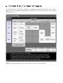
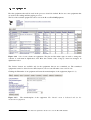
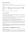
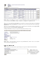
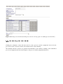
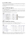
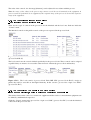
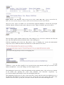
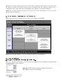
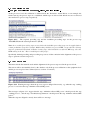
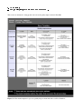
0-0: 9&3 #$&¡ ¢7¢ +M£Q¤¥ #¦$§& 9N +3>0£&¨©&I¥0ª1¨T&§=«+&¬¦0 ¢7¢ At the processes level, the validation is defined inside the “Relations” menu. Below, as an example, the relation among the process steps are established: which steps are allowed and which ones are not allowed after and before a process step respectively. Figure 4.2.1 The required preceding step and the forbidden proceeding steps for the process step “Etch,RIE,SF6,check/ set/read parameters” (ID 90). Note: the re-enabled proceeding steps are used when the forbidden proceeding steps can be applied after a certain preliminary steps. For example: KOH etching should never proceed RIE, except when the cleaning steps are performed beforehand. So at the cleaning step, which should be set after the RIE step, select the KOH etching in the box “The re-enabled proceeding steps”. Specifically defined preceding and proceeding steps can avoid the confusion in the alignment of the process steps to perform a cleanroom process. ®¯±°²0³´q²³ µ$¶N·#³0¸¹ This menu checks the materials used and the alignment of the process steps used in the process block. This action will be automatically done by the database only if the process validations at the equipment level and the process step level were defined (refer to sections 4.1 and 4.2). Figure 4.3.1 Warning message when the process steps are alligned incorrectly, e.g. when the step “etching process” is set before the step “minimize reflected RF power”. The messages at figure 4.3.1 suggest that the step “minimize reflected RF power” should precede the step “etching process” , and the step “check/set/read parameters” should precede the step “minimize reflected RF power”. When the steps are alligned correctly, there will be no message.