1
HSXA15
HSXB15
Corp. 0128−L12
Revised 10−2004
Service Literature
HSXA15 & HSXB15 SERIES UNITS
The HSXA15 and HSXB15 are high efficiency residential
split−system condensing units, which features a scroll compressor and R410A refrigerant. HSXA15 and HSXB15
units are available in sizes ranging from 2 through 5 tons.
The series is designed for use with an expansion valve only
(approved for use with R410A) in the indoor unit.This
manual is divided into sections which discuss the major
components, refrigerant system, charging procedure,
maintenance and operation sequence.
Information contained in this manual is intended for use by
qualified service technicians only. All specifications are
subject to change.
IMPORTANT
Operating pressures of this R410A unit are higher
than pressures in R22 units. Always use service
equipment rated for R410A.
WARNING
Improper installation, adjustment, alteration, service
or maintenance can cause property damage, personal injury or loss of life. Installation and service must
be performed by a qualified installer or service
agency.
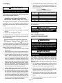
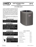
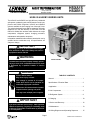
HSXB15 SHOWN
DANGER
TABLE OF CONTENTS
Electric Shock Hazard.
May cause injury or death.
General . . . . . . . . . . . . . . . . . . . . . . . . . . . . . . . . . . . . . . 1
Line voltage is present at all components when unit is not in operation on
units with single pole contactors.
Disconnect all remote electrical power
supplies before opening unit panel.
Specifications / Electrical Data . . . . . . . . . . . . . . . . . . . 2
I Application . . . . . . . . . . . . . . . . . . . . . . . . . . . . . . . . . . 4
II Unit Components . . . . . . . . . . . . . . . . . . . . . . . . . . . . 4
Unit may have multiple power supplies.
III Refrigerant System . . . . . . . . . . . . . . . . . . . . . . . . . . 9
IV Charging . . . . . . . . . . . . . . . . . . . . . . . . . . . . . . . . . . . 10
IMPORTANT
The Clean Air Act of 1990 bans the intentional venting of (CFC’s and HFC’s) as of July 1, 1992. Approved
methods of recovery, recycling or reclaiming must
be followed. Fines and/or incarceration my be levied
for noncompliance.
Page 1
V Service and Recovery . . . . . . . . . . . . . . . . . . . . . . . . 12
VI Maintenance . . . . . . . . . . . . . . . . . . . . . . . . . . . . . . . 13
VII Wiring Diagrams and Operating Sequence . . . . . 15
©2001Lennox Industries Inc.
HSXA15
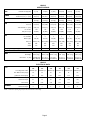
SPECIFICATIONS
General
D t
Data
Model No.
HSXA15−024
HSXA15−030
HSXA15−042
HSXA15−048
HSXA15−060
2 (7.0)
2.5 (8.8)
3 (10.6)
3.5 (12.3)
4 (14.1)
5 (17.6)
Liquid line (o.d.) − in. (mm)
3/8 (9.5)
3/8 (9.5)
3/8 (9.5)
3/8 (9.5)
3/8 (9.5)
3/8 (9.5)
Suction line (o.d.) − in. (mm)
3/4 (19.1)
3/4 (19.1)
3/4 (19.1)
7/8 (22.2)
7/8 (22.2)
1−1/8 (28.6)
Refrigerant
R−410A charge furnished
5 lbs. 1 oz.
(2.28 kg)
5 lbs. 10 oz.
(2.54 kg)
7 lbs. 8 oz.
(3.39 kg)
7 lbs. 13 oz.
(3.53 kg)
7 lbs. 13 oz.
(3.53 kg)
10 lbs.15 oz.
(4.95 kg)
Condenser
Coil
Net face area − sq. ft. (m2) Outer coil
11.9 (1.11)
16 (1.49)
16 (1.49)
16 (1.49)
18.3 (1.70)
21.8 (2.03)
Inner coil
5.5 (0.51)
5.6 (0.52)
13.3 (1.24)
13.3 (1.24)
13.3 (1.24)
21.1 (1.96)
Tube diameter − in. (mm)
5/16 (7.9)
5/16 (7.9)
5/16 (7.9)
5/16 (7.9)
5/16 (7.9)
5/16 (7.9)
1.46
1.35
1.83
1.83
1.73
2
Fins per inch (m)
22 (866)
22 (866)
22 (866)
22 (866)
22 (866)
22 (866)
Diameter − in. (mm)
20 (508)
24 (610)
24 (610)
24 (610)
24 (610)
24 (610)
No. of blades
4
3
3
3
3
3
Motor hp (W)
1/6 (124)
1/6 (124)
1/6 (124)
1/6 (124)
1/4 (187)
1/4 (187)
2450 (1115)
3150 (1485)
3150 (1485)
3150 (1485)
3900 (1840)
4200 (1980)
Rpm
825
825
825
825
820
820
Watts
210
225
225
225
310
350
187 (85)
222 (101)
238 (108)
238 (108)
258 (117)
312 (142)
Connections
(sweat)
Nominal Tonnage (kW)
HSXA15−036
No. of rows
Condenser
Fan
Cfm (L/s)
Shipping Data (1 package)
lbs. (kg)
OPTIONAL ACCESSORIES − MUST BE ORDERED EXTRA
Mounting
Base
Model No.
Net Weight
MB2−S (69J06) MB2−L (69J07) MB2−L (69J07) MB2−L (69J07) MB2−L (69J07) MB2−L (69J07)
6 lbs. (3 kg)
Dimensions − in. (mm) 22−1/4x22−1/4x3
(565 x 565x76)
15 lbs. (7 kg)
15 lbs. (7 kg)
15 lbs. (7 kg)
15 lbs. (7 kg)
15 lbs. (7 kg)
32 x 34 x 3
32 x 34 x 3
32 x 34 x 3
32 x 34 x 3
32 x 34 x 3
(813x864x76) (813x864x76) (813x864x76) (813x864x76) (813x864x76)
HSXA15
ELECTRICAL DATA
General
Data
Compressor
Model No.
HSXA15−024
−230
HSXA15−030
−230
HSXA15−036
−230
HSXA15−042
−230
HSXA15−048
−230
HSXA15−060
−230
Line voltage data − 60hz
208/230v−1ph
208/230v−1ph
208/230v−1ph
208/230v−1ph
208/230v−1ph
208/230v−1ph
Rec. Max fuse size (amps)
30
30
35
40
45
60
Minimum circuit ampacity
17.9
19.6
20.4
25.3
27.5
36.2
Rated load amps
13.5
14.8
15.4
19.3
20.6
27.6
Locked rotor amps
Condenser
Fan Motor
61
73
83
104
109
158
Power factor
0.98
0.98
0.95
0.97
0.97
0.98
Full load amps
1.1
1.1
1.1
1.1
1.7
1.7
2
2
2
2
3.1
3.1
Locked rotor amps
Refer to National or Canadian Electrical Code manual to determine wire, fuse and disconnect size requirements.
NOTE Extremes of operating range are plus 10% and minus 5% of line voltage.
Page 2
HSXB15
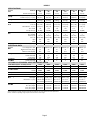
SPECIFICATIONS
Model No.
General
Data
Nominal Tonnage (kW)
Connections
(
(sweat)
t)
Liquid line (o.d.) − in. (mm)
Suction line (o.d.) − in. (mm)
1R−410A
Refrigerant
Condenser
C il
Coil
charge furnished
HSXB15−024
−230
HSXB15−030
−230
HSXB15−036
−230
HSXB15−042
−230
2 (7.0)
3/8 (9.5)
HSXB15−048
−230
HSXB15−060
−230
2.5 (8.8)
3 (10.6)
3.5 (12.3)
4 (14.1)
5 (17.6)
3/8 (9.5)
3/8 (9.5)
3/8 (9.5)
3/8 (9.5)
3/8 (9.5)
3/4 (19.1)
3/4 (19.1)
3/4 (19.1)
7/8 (22.2)
7/8 (22.2)
1−1/8 (28.6)
4 lbs. 10 oz.
(2.10 kg)
5 lbs. 10 oz.
(2.55 kg)
7 lbs. 8 oz.
(3.40 kg)
7 lbs. 13 oz.
(3.54 kg)
7 lbs. 13 oz.
(3.54 kg)
10 lbs. 13 oz.
(4.90 kg)
Net face area − sq. ft. (m2) Outer coil
11.9 (1.11)
16 (1.49)
16 (1.49)
16 (1.49)
18.3 (1.70)
21.8 (2.03)
Inner coil
5.5 (0.51)
5.6 (0.52)
13.3 (1.24)
13.3 (1.24)
13.3 (1.24)
21.1 (1.96)
Tube diameter − in. (mm)
5/16 (7.9)
5/16 (7.9)
5/16 (7.9)
5/16 (7.9)
5/16 (7.9)
5/16 (7.9)
1.46
1.35
1.83
1.83
1.73
2
Fins per inch (m)
22 (866)
22 (866)
22 (866)
22 (866)
22 (866)
22 (866)
Diameter − in. (mm)
24 (610)
No. of rows
Condenser
F
Fan
20 (508)
24 (610)
24 (610)
24 (610)
24 (610)
No. of blades
3
3
3
3
3
3
Motor hp (W)
1/10 (75)
1/6 (124)
1/6 (124)
1/6 (124)
1/4 (187)
1/4 (187)
Cfm (L/s)
Shipping Data
2230 (1050)
3150 (1485)
3150 (1485)
3150 (1485)
3900 (1840)
4100 (1935)
Rpm
825
825
825
825
820
825
Watts
125
225
225
225
310
320
190 (86)
227 (103)
243 (110)
243 (110)
263 (119)
317 (144)
208/230v−1ph
lbs. (kg) 1 pkg.
ELECTRICAL DATA
General
D t
Data
Line voltage data − 60hz
208/230v−1ph
208/230v−1ph
208/230v−1ph
25
30
40
40
45
60
circuit ampacity
16.6
19.6
23.5
25.3
27.5
36.2
Rated load amps
12.8
14.8
17.9
19.3
20.6
27.6
60
73
95
104
109
158
Power factor
0.98
0.98
0.95
0.97
0.97
0.98
Full load amps
0.6
1.1
1.1
1.1
1.7
1.7
Locked rotor amps
1.6
2
2
2
3.1
3.1
Maximum fuse size (amps)
2Minimum
Compressor
p
Locked rotor amps
Condenser
F M
Fan
Motor
t
208/230v−1ph 208/230v−1ph
OPTIONAL ACCESSORIES − MUST BE ORDERED EXTRA
CCB1 EfficiencyPlust Humidity Control
35H00
35H00
35H00
35H00
35H00
35H00
EBR1 Blower Relay Kit (for CCB1)
75H90
75H90
75H90
75H90
75H90
75H90
40 watt
18K20
18K20
18K20
18K20
−−−
−−−
70 watt
67K90
67K90
67K90
67K90
31J20
31J20
Compressor
p
C
Crankcase
k
Heater
H t
Compressor Hard Start Kit
10J42
10J42
10J42
10J42
10J42
81J69
Low Ambient Kit
34M72
34M72
34M72
34M72
34M72
34M72
Mounting
g
B
Base
Refrigerant
g
Li S
Line
Sett
Model No. MB2−S (69J06) MB2−L (69J07) MB2−L (69J07) MB2−L (69J07) MB2−L (69J07) MB2−L (69J07)
Net Weight
15 lbs. (7 kg)
15 lbs. (7 kg)
15 lbs. (7 kg)
15 lbs. (7 kg)
15 lbs. (7 kg)
Dimensions − in. (mm) 22−1/4x22−1/4x3 32 x 34 x 3
(565 x 565x76) (813x864x76)
6 lbs. (3 kg)
32 x 34 x 3
(813x864x76)
32 x 34 x 3
(813x864x76)
32 x 34 x 3
(813x864x76)
32 x 34 x 3
(813x864x76)
15 ft. (4.6 m) length
L15−41−15
L15−41−15
L15−41−15
L15−65−15
L15−65−15
Field Fabricate
30 ft. (9 m) length
L15−41−30
L15−41−30
L15−41−30
L15−65−30
L15−65−30
Field Fabricate
40 ft. (12 m) length
L15−41−40
L15−41−40
L15−41−40
L15−65−40
L15−65−40
Field Fabricate
50 ft. (15 m) length
L15−41−50
L15−41−50
L15−41−50
L15−65−50
L15−65−50
Field Fabricate
1Refrigerant charge sufficient for 15 ft. (4.6 m) length of refrigerant lines.
2Refer to National or Canadian Electrical Code manual to determine wire,
fuse and disconnect size requirements.
NOTE Extremes of operating range are plus 10% and minus 5% of line voltage.
Page 3
I−APPLICATION
All major components (indoor blower and coil) must be
matched according to Lennox recommendations for the
compressor to be covered under warranty. Refer to the Engineering Handbook for approved system matchups. A
misapplied system will cause erratic operation and can result in early compressor failure.
SCROLL FORM
II−Unit Components
The contactor coil, time delay (HSXA15−1 units only) and
Lennox system operation monitor are energized by
24VAC supplied by the indoor unit. All other components
in the outdoor unit are powered by line voltage. Refer to
unit wiring diagram. The HSXA15 and HSXB15 units are
not equipped with an internal line voltage to 24V transformer.
FIGURE 2
CROSS−SECTION OF SCROLLS
DISCHARGE
DISCHARGE
PRESSURE
STATIONARY SCROLL
SUCTION
A−Scroll Compressor (B1)
SCROLL COMPRESSOR
DISCHARGE
TIPS SEALED BY
DISCHARGE PRESSURE
SUCTION
FIGURE 1
The scroll compressors in all units are designed for use
with R410A refrigerant and operation at high pressures.
Compressors are shipped from the factory with 3MA
(32MMMA) P.O.E. oil.. See electrical section in this manual
for compressor specifications.
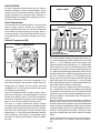
The scroll compressor design is simple, efficient and requires few moving parts. A cutaway diagram of the scroll
compressor is shown in figure 1.The scrolls are located in
the top of the compressor can and the motor is located just
below. The oil level is immediately below the motor.
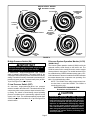
The scroll is a simple compression concept centered
around the unique spiral shape of the scroll and its inherent
properties. Figure 2 shows the basic scroll form. Two identical scrolls are mated together forming concentric spiral
shapes (figure 3 ). One scroll remains stationary, while the
other is allowed to orbit" (figure 4). Note that the orbiting
scroll does not rotate or turn but merely orbits" the stationary scroll.
ORBITING SCROLL
FIGURE 3
The counterclockwise orbiting scroll draws gas into the outer crescent shaped gas pocket created by the two scrolls
(figure 4 − 1). The centrifugal action of the orbiting scroll
seals off the flanks of the scrolls (figure 4 − 2). As the orbiting
motion continues, the gas is forced toward the center of the
scroll and the gas pocket becomes compressed (figure 4
−3). When the compressed gas reaches the center, it is discharged vertically into a chamber and discharge port in the
top of the compressor (figure1). The discharge pressure
forcing down on the top scroll helps seal off the upper and
lower edges (tips) of the scrolls (figure 3 ). During a single
orbit, several pockets of gas are compressed simultaneously providing smooth continuous compression.
The scroll compressor is tolerant to the effects of liquid return. If liquid enters the scrolls, the orbiting scroll is allowed
to separate from the stationary scroll. The liquid is worked
toward the center of the scroll and is discharged. If the compressor is replaced, conventional Lennox cleanup practices must be used.
Due to its efficiency, the scroll compressor is capable of
drawing a much deeper vacuum than reciprocating compressors. Deep vacuum operation can cause internal fusite
arcing resulting in damaged internal parts and will result in
compressor failure. Never use a scroll compressor for evacuating or pumping−down" the system. This type of damage can be detected and will result in denial of warranty
claims.
NOTE − During operation, the head of a scroll compressor
may be hot since it is in constant contact with discharge
gas.
Page 4
HOW A SCROLL WORKS
MOVEMENT OF ORBIT
SUCTION
SUCTION
INTERMEDIATE
PRESSURE
GAS
CRESCENT
SHAPED GAS
POCKET
ORBITING
SCROLL
SUCTION
POCKET
1
2
SUCTION
STATIONARY SCROLL
FLANKS
SEALED BY
CENTRIFUGAL
FORCE
3
SUCTION
4
HIGH
PRESSURE
GAS
DISCHARGE
POCKET
FIGURE 4
B−High Pressure Switch (S4)
D−Lennox System Operation Monitor (A132)
(HSXB15 Only)
IMPORTANT
Pressure switch settings for R410A refrigerant will
be significantly higher than units with R22.
A manual-reset, single-pole/single-throw high pressure
switch is located in the liquid line. This switch shuts off the
compressor when liquid line pressure rises above the factory
setting. The switch is normally closed and is permanently adjusted to trip (open) at 640 + 10 psi and reset (close) at 448 +
10 psi. See figure 5 for switch location.
C−Low Pressure Switch (S87)
An auto-reset, single-pole/single-throw low pressure
switch is located in the suction line. This switch shuts off the
compressor when suction pressure drops below the factory setting. The switch is closed during normal operating
pressure conditions and is permanently adjusted to trip
(open) at 40 + 5 psi. The switch automatically resets when
suction line pressure rises above 90 + 5 psi. See figure 5 for
switch location.
Page 5
The Lennox system operation monitor (LSOM) is a 24 volt
powered module, wired directly to the indoor unit. The
LSOM is located in the control box and is used to trouble
shoot problems in the system. The module has three LED’s
for troubleshooting: GREEN indicates power status, YELLOW indicates an abnormal condition and RED indicates
thermostat demand, but compressor not operating. See
table 1 for troubleshooting codes.
NOTE − The LSOM is not a safety component and cannot shut down or control the HSXB15. The LSOM is a
monitoring device only.
ELECTROSTATIC DISCHARGE (ESD)
Precautions and Procedures
CAUTION
Electrostatic discharge can affect electronic
components. Take precautions during unit installation and service to protect the unit’s electronic
controls. Precautions will help to avoid control
exposure to electrostatic discharge by putting
the unit, the control and the technician at the
same electrostatic potential. Neutralize electrostatic charge by touching hand and all tools on an
unpainted unit surface before performing any
service procedure.
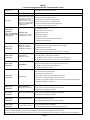
TABLE 1
Lennox System Operation Monitor Troubleshooting Codes
Status LED
Status LED Description
Green Power"
Module has power.
Red Trip"
Thermostat demand signal
Y1 is present, but the compressor is not running.
Heat pump only − Trip light
will be on during defrost
board 5 minute delay with Y
thermostat call.
Status LED Troubleshooting Information
Supply voltage is present at module terminals.
1
Compressor protector is open.
2 Outdoor
unit power disconnect is open.
3 Compressor
4 Broken
5 Low
wire or connector is not making contact.
pressure switch open if present in the system.
6 Compressor
1
circuit breaker or fuse(s) is open.
contactor has failed to close.
Low refrigerant charge.
Yellow Alert"
2 Evaporator
blower is not running.
Flash Code 1
(Does not apply to heat
pump or to two−stage
split systems)
Long Run Time
3 Evaporator
coil is frozen.
Compressor is running
extremely long run cycles
4 Faulty
metering device.
5 Condenser
6 Liquid
7 Thermostat
System Pressure Trip
Yellow Alert"
Flash Code 2
Discharge or suction
pressure out of limits or
compressor overloaded
1
Short Cycling
Compressor is
running only briefly
Flash Code 3
High head pressure.
coil poor air circulation (dirty, blocked, damaged).
3 Condenser
fan is not running.
4 Return
1
Flash Code 4
Locked Rotor
air duct has substantial leakage.
low pressure switch is present, check Flash Code 1 information.
Thermostat demand signal is intermittent.
2 Time
delay relay or control board is defective.
3 If
high pressure switch is present, check Flash Code 2 information.
4 If
low pressure switch is present, check Flash Code 1 information.
1
Yellow Alert"
is malfunctioning.
2 Condenser
5 If
Yellow Alert"
coil is dirty
line restriction (filter drier blocked if present)
Run capacitor has failed.
2 Low
line voltage (contact utility if voltage at disconnect is low).
3 Excessive
liquid refrigerant in the compressor.
4 Compressor
1
Yellow Alert"
Open Circuit
Flash Code 5
Outdoor unit power disconnect is open.
2 Unit
circuit breaker or fuse(s) is open.
3 Unit
contactor has failed to close.
4 High
pressure switch is open and requires manual reset.
5 Open
circuit in compressor supply wiring or connections.
6 Unusually
long compressor protector reset time due to extreme ambient temperature.
7 Compressor
1
Yellow Alert"
Flash Code 6
Yellow Alert"
Open Start Circuit
Current only in run circuit
Welded Contactor
Compressor always runs
Flash Code 9
1
Low Voltage
Control circuit < 17VAC
1
start winding is damaged.
Open circuit in compressor start wiring or connections.
start winding is damaged.
Compressor contactor failed to open.
2 Thermostat
Flash Code 8
Yellow Alert"
circuit in compressor start wiring or connections.
2 Compressor
Flash Code 7
Yellow Alert"
1
windings are damaged.
Run capacitor has failed.
2 Open
3 Compressor
Open Run Circuit
Current only in start circuit
bearings are seized.
demand signal not connected to module.
Control circuit transformer is overloaded
2 Low
line voltage (contact utility if voltage at disconnect is low).
Flash code number corresponds to a number of LED flashes, followed by a pause, and then repeated.
TRIP and ALERT LEDs flashing at the same time indicates that the control circuit voltage is too low for operation.
Reset ALERT flash code by removing 24VAC power from monitor. Last ALERT flash code will display for 1 minute after monitor is powered on.
Page 6
E−TOC Timed Off Control
(HSXA15−1 Units Only)
F−Dual Capacitor (C12)
HSXA15−1 units are equipped with a TOC, (timed off control). The TOC is located in the control box (figure 5). The
TOC is electrically connected between thermostat terminal
Y and the compressor contactor. When thermostat demand
is satisfied, the TOC opens the circuit to the compressor
contactor coil and the compressor is de−energized. Between
cycles, the compressor contactor is delayed for 5 minutes +
2 minutes. At the end of the delay, the compressor is allowed
to energize. Without the time delay it would be possible to
short cycle the compressor.
The compressor and fan in all units use permanent split capacitor motors. A single dual" capacitor is used for both the
fan motor and the compressor (see unit wiring diagram).
The two sides (fan and compressor) of the capacitor have
different mfd ratings and may change with each compressor. The capacitor is located inside the unit control box.
G−Contactor (K1)
The compressor is energized by a contactor located in the
control box. All units are single−phase with single−pole contactors. See figure 5 for location.
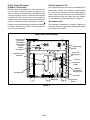
HSXB15 PARTS ARRANGEMENT
condenser fan
(not shown)
top of cabinet
Lennox system
operation
monitor
ground lug
contactor
run capacitor
vapor valve
and gauge port
compressor power
terminals
vapor line
low pressure
switch
liquid line
service valve
and gauge port
discharge line
filter drier
compressor
FIGURE 5
Page 7
high pressure
switch
If oil sample taken from a system that has been exposed to
open air does not test in the dry color range, the filter drier
MUST be replaced.
H−Filter Drier
A filter drier designed for all HSXA15 model units is factory
supplied and must be installed in the liquid line. The filter
drier for the HSXB15 units is factory installed in the liquid
line. The filter drier is designed to remove moisture and foreign matter, which can lead to compressor failure.
IMPORTANT
Replacement filter drier MUST be approved for
Moisture and / or Acid Check
R410A refrigerant and POE application.
Because POE oils absorb moisture, the dryness of the
system must be verified any time the refrigerant sysForeign Matter Check
tem is exposed to open air. A compressor oil sample
must be taken to determine if excessive moisture has been
It is recommended that a liquid line filter drier be replaced
introduced to the oil. Table 2 lists kits available from Lennox
when the pressure drop across the filter drier is greater
to check POE oils.
than 3 psig.
TABLE 2
KIT
CONTENTS
TUBE SHELF LIFE
10N46 − Refrigerant Analysis
Checkmate−RT700
10N45 − Acid Test Tubes
Checkmate−RT750A (three pack)
2 − 3 years @ room temperature. 3+
years refrigerated
10N44 − Moisture Test Tubes
Checkmate − RT751 Tubes (three
pack)
6 − 12 months @ room temperature. 2
years refrigerated
74N40 − Easy Oil Test Tubes
Checkmate − RT752C Tubes (three
pack)
2 − 3 years @ room temperature. 3+
years refrigerated
74N39 − Acid Test Kit
Sporlan One Shot − TA−1
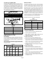
MEASURING FILTER DRIER PRESSURE DROP
1− Shut off power to unit.
2− Remove high pressure switch from fitting next to filter drier.
(A schrader core is located under the high pressure switch).
3− Install high pressure gauge hose onto high pressure switch fitting.
4− Turn power on to unit and turn room thermostat to call for cooling.
5− Record pressure reading on gauge.
6− Remove hose from high pressure fitting and install on liquid line valve.
7− Read liquid line valve pressure.
8− High pressure fitting pressure − liquid line valve pressure = filter drier
pressure drop.
9− If pressure drop is greater than 4 psig replace filter drier. See figure 7.
10− Re−install high pressure switch.
FIGURE 6
REPLACING FILTER DRIER
1− Recover all refrigerant from unit.
2− Remove original filter drier.
3− Install new filter drier in existing location or alternate location as
shown. Proper brazing procedures should be followed.
4− Evacuate system. See section IV− part B−.
5− Recharge system. See section IV− part C−.
FIGURE 7
Page 8
I−Condenser Fan Motor (B4)
B−Service Valves
All units use single−phase PSC fan motors which require a
run capacitor. The FAN" side of the dual capacitor is used
for this purpose. The specifications tables on page 1 and 2
of this manual show the specifications of outdoor fans used
in HSXA15 units. In all units, the outdoor fan is controlled
by the compressor contactor. See figure 8 if condenser fan
motor replacement is necessary.
The liquid line and vapor line service valves and gauge
ports are accessible by removing the compressor access
cover. Full service liquid and vapor line valves are used.
See figures 9 and 10. The service ports are used for leak
testing, evacuating, charging and checking charge. Service valves have a factory−installed schrader valve. A service port cap is supplied to protect the schrader valve from
contamination and assure a leak free seal. Valves are not
rebuildable. If a valve has failed it must be replaced. The
pressure tap fitting has a LIGHT MAROON tag to remind
service technicians that the unit contains R410A.
IMPORTANT
Route fan motor leads away from fan blades when
replacing fan motor. Use wire drip loop as shown
in figure 8.
See table 5 for sevice valve torque requirements.
FAN
GUARD
"A" SEE TABLE 3
Table 5
Torque Requirements
Part
Condenser fan
and motor
Wiring
Drip loop
FIGURE 8
TABLE 3
HSXA/B15 UNIT
"A" DIM. + 1/8"
−024
1 1/4"
−030
2"
−036, −042
1 1/2"
−048
2 1/16"
−060
2 1/16"
−024
−030
−036
3/8 in.
(10 mm)
3/4 in.
(19 mm)
3/8 in.
(10 mm)
−042
−048
3/8 in.
(10 mm)
7/8 in.
(22 mm)
−060
3/8 in.
(10 mm)
1−1/8 in.
(29 mm)
Liquid
Line
Sheet metal screws
16 in.− lb.
2 NM
Machine screws #10
28 in.− lb.
3 NM
Compressor bolts
90 in.− lb.
10 NM
Gauge port seal cap
8 ft.− lb.
11 NM
3 − When testing is complete, replace service port cap.
Tighten finger tight, then an additional 1/6 turn.
To Open Service Valve:
Recommended Line Set
Vapor
Line
11 NM
2 − Connect gauge to the service port.
TABLE 4
Liquid
Line
8 ft.− lb.
1 − Remove service port cap with an adjustable wrench.
Field refrigerant piping consists of liquid and suction lines
from the outdoor unit (sweat connections). Use Lennox
L15 series line sets as shown in table 4 or field−fabricated
refrigerant lines.
Separate discharge and suction service ports are provided
at the compressor for connection of gauge manifold during
charging procedure.
Valve Field Size
Connections
Service valve cap
To Access Schrader Port:
III−REFRIGERANT SYSTEM
A−Plumbing
Model
No.
Recommended Torque
Vapor
Line
1 − Remove the stem cap with an adjustable wrench.
2 − Use a service wrench with a hex−head extension to
back the stem out counterclockwise as far as it will go.
NOTE − Use a 3/16" hex head extension for liquid line
sizes or a 5/16" extension for vapor line sizes.
3 − Replace the stem cap. Tighten finger tight, then tighten
an additional 1/6 turn.
To Close Service Valve:
L15
Line Sets
1 − Remove the stem cap with an adjustable wrench.
3/4 in.
(19 mm)
L15−41
15 ft. − 50 ft.
(4.6 m − 15 m)
2 − Use a service wrench with a hex−head extension to
turn the stem clockwise to seat the valve. Tighten the
stem firmly.
3/8 in.
(10 mm)
7/8 in.
(22 mm)
L15−65
15 ft. − 50 ft.
(4.6 m − 15 m)
NOTE − Use a 3/16" hex head extension for liquid line
sizes or a 5/16" extension for vapor line sizes.
3/8 in.
(10 mm)
1−1/8 in.
(29 mm)
Field
Fabricated
Page 9
3 − Replace the stem cap. Tighten finger tight, then tighten
an additional 1/6 turn.
IV−CHARGING
Service Valve
(Valve Closed)
stem cap
service
port
insert hex
wrench here
to outdoor coil
Units are factory charged with the amount of R410A refrigerant indicated on the unit rating plate. This charge is
based on a matching indoor coil and outdoor coil with 15 ft.
(4.5m) line set. For varying lengths of line set, refer to table
6 for refrigerant charge adjustment.
TABLE 6
Liquid Line Set
Diameter
3/8 in.
(10mm)
service
port cap
to indoor coil
Schrader valve open
to line set when valve is
closed (front seated)
(valve front seated)
insert hex
wrench here
Service Valve
(Valve Open)
stem cap
Ozs. per 5 ft. (grams per 1.5m) adjust
from 15 ft. (4.5m) line set*
3 ounces per 5 feet
(85g per 1.5m)
*If line length is greater than 15 ft. (4.5 m), add this amount.
If line length is less than 15 ft. (4.5m), subtract this amount.
A−Leak Testing
After the line set has been connected to the indoor and
outdoor units, check the line set connections and indoor
unit for leaks.
service
port
WARNING
to outdoor coil
Refrigerant can be harmful if it is inhaled. Refrigerant
must be used and recovered responsibly.
Failure to follow this warning may result in personal
injury or death.
service port
cap
to indoor coil
WARNING
Schrader
valve
Danger of explosion: Can cause
equipment damage, injury or death.
Never use oxygen to pressurize a refrigeration or air conditioning system.
Oxygen will explode on contact with
oil and could cause personal injury.
FIGURE 9
Vapor Line Ball Valve 5 ton Only
Vapor line ball valves function the same way as the other
valves, the difference is in the construction. These valves
are not rebuildable. If a valve has failed, you must replace
it. A ball valve is illustrated in figure 10.
Ball Valve (Valve Open)
Use Adjustable Wrench
To open: rotate Stem Clockwise 90°.
To close: rotate Stem Counter-clockwise 90°.
stem cap
to outdoor coil
stem
to indoor coil
service port
Schrader valve
FIGURE
10
Danger of explosion: Can cause equipment damage,
injury or death. When using a high pressure gas
such as dry nitrogen to pressurize a refrigeration or
air conditioning system, use a regulator that can
control the pressure down to 1 or 2 psig (6.9 to 13.8
kPa).
Using an Electronic Leak Detector or Halide
ball
(shown open)
service port
cap
WARNING
1 − Connect a cylinder of R410A to the center port of the
manifold gauge set.
2 − With both manifold valves closed, open the valve on
the R410A cylinder (vapor only).
3 − Open the high pressure side of the manifold to allow
the R410A into the line set and indoor unit. Weigh in a
trace amount of R410A. [A trace amount is a maximum
of 2 ounces (57 g) or 3 pounds (31 kPa) pressure.]
Close the valve on the R410A cylinder and the valve on
the high pressure side of the manifold gauge set. Disconnect the R410A cylinder.
4 − Connect a cylinder of nitrogen with a pressure regulating valve to the center port of the manifold gauge set.
Page 10
5 − Connect the manifold gauge set high pressure hose to
the vapor valve service port. (Normally, the high pressure hose is connected to the liquid line port; however,
connecting it to the vapor port better protects the manifold gauge set from high pressure damage.)
NOTE − The term absolute pressure means the total
actual pressure within a given volume or system,
above the absolute zero of pressure. Absolute pressure in a vacuum is equal to atmospheric pressure minus vacuum pressure.
6 − Adjust the nitrogen pressure to 150 psig (1034 kPa).
Open the valve on the high side of the manifold gauge
set which will pressurize line set and indoor unit.
6 − When the absolute pressure reaches 23,000 microns
(29.01 inches of mercury), close the manifold gauge
valves, turn off the vacuum pump and disconnect the
manifold gauge center port hose from vacuum pump.
Attach the manifold center port hose to a nitrogen cylinder with pressure regulator set to 150 psig (1034 kPa)
and purge the hose. Open the manifold gauge valves
to break the vacuum in the line set and indoor unit.
Close the manifold gauge valves.
7 − After a few minutes, open a refrigerant port to ensure
the refrigerant you added is adequate to be detected.
(Amounts of refrigerant will vary with line lengths.)
Check all joints for leaks. Purge nitrogen and R410A
mixture. Correct any leaks and recheck.
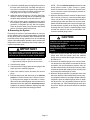
B−Evacuating the System
Evacuating the system of noncondensables is critical for
proper operation of the unit. Noncondensables are defined
as any gas that will not condense under temperatures and
pressures present during operation of an air conditioning
system. Noncondensables and water vapor combine with
refrigerant to produce substances that corrode copper piping and compressor parts.
IMPORTANT
Use a thermocouple or thermistor electronic vacuum
gauge that is calibrated in microns. Use an instrument
that reads from 50 microns to at least 10,000 microns.
1 − Connect manifold gauge set to the service valve ports :
low pressure gauge to vapor line service valve
high pressure gauge to liquid line service valve
2 − Connect micron gauge.
3 − Connect the vacuum pump (with vacuum gauge) to the
center port of the manifold gauge set.
4 − Open both manifold valves and start the vacuum
pump.
5 − Evacuate the line set and indoor unit to an absolute
pressure of 23,000 microns (29.01 inches of mercury). During the early stages of evacuation, it is desirable to close the manifold gauge valve at least once to
determine if there is a rapid rise in absolute pressure.
A rapid rise in pressure indicates a relatively large leak.
If this occurs, repeat the leak testing procedure.
Page 11
CAUTION
Danger of Equipment Damage.
Avoid deep vacuum operation. Do not use compressors to evacuate a system.
Extremely low vacuums can cause internal arcing
and compressor failure.
Damage caused by deep vacuum operation will void
warranty.
7 − Shut off the nitrogen cylinder and remove the manifold
gauge hose from the cylinder. Open the manifold
gauge valves to release the nitrogen from the line set
and indoor unit.
8 − Reconnect the manifold gauge to the vacuum pump,
turn the pump on, and continue to evacuate the line set
and indoor unit until the absolute pressure does not
rise above 500 microns (29.9 inches of mercury) within
a 20−minute period after shutting off the vacuum pump
and closing the manifold gauge valves.
9 − When the absolute pressure requirement above has
been met, disconnect the manifold hose from the vacuum pump and connect it to an upright cylinder of R410A
refrigerant. Open the manifold gauge valves to break
the vacuum from 1 to 2 psig positive pressure in the line
set and indoor unit. Close manifold gauge valves and
shut off the R410A cylinder and remove the manifold
gauge set.
C−Charging
IMPORTANT
Mineral oils are not compatible with R410A. If oil
must be added, it must be a polyol ester oil.
5 − If the values don’t agree with the those in table 7, add
refrigerant to lower the approach temperature or recover refrigerant from the system to increase the approach temperature.
TABLE 7
APPROACH TEMPERATURES
HSXA/B15
Unit
Approach Temperature
Liquid Line Temp. − Outdoor Ambient °F
−024
8±1
−030
8±1
−036
6±1
−042
9±1
−048
8±1
−060
12 ± 1
The compressor is charged with sufficient polyol ester
oil for line set lengths up to 50 ft.
Weighing in the Charge Fixed Orifice or
TXV Systems – Outdoor Temp < 65F (18C)
If the system is void of refrigerant, or if the outdoor ambient
temperature is cool, the refrigerant charge should be
weighed into the unit. Do this after any leaks have been repaired.
NOTE − For best results, the same electronic thermometer
should be used to check both outdoor ambient and liquid
line temperatures.
IMPORTANT
1 − Recover the refrigerant from the unit.
2 − Conduct a leak check, then evacuate as previously
outlined.
REFRIGERANT SHOULD BE ADDED THROUGH
THE SUCTION VALVE IN THE LIQUID STATE.
3 − Weigh in the unit nameplate charge.
D−Oil Charge
If weighing facilities are not available or if you are charging
the unit during warm weather, follow one of the other procedures outlined below.
Refer to compressor nameplate.
Approach and Normal Operating Pressures
TXV Systems – Outdoor Temp. > 65F (18C)
The following procedure is intended as a general guide and
is for use on expansion valve systems only. For best results,
indoor temperature should be 70°F (21°C) to 80°F (26°C).
Monitor system pressures while charging.
1 − Record outdoor ambient temperature using a digital
thermometer.
2 − Attach high pressure gauge set and operate unit for
several minutes to allow system pressures to stabilize.
3 − Compare stabilized pressures with those provided in
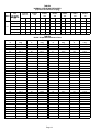
table 8, Normal Operating Pressures." Minor variations in these pressures may be expected due to differences in installations. Significant differences could
mean that the system is not properly charged or that a
problem exists with some component in the system.
Pressures higher than those listed indicate that the
system is overcharged. Pressures lower than those
listed indicate that the system is undercharged. Verify
adjusted charge using the approach method.
4 − Outdoor temperature should be 65°F (18°C) or above.
Use the same digital thermometer used to check outdoor ambient temperature to check liquid line temperature. Verify the unit charge using the approach method.
The difference between the ambient and liquid temperatures should match values given in table 3. Refrigerant must be added to lower approach temperature and
removed to increase approach temperature. Loss of
charge results in low capacity and efficiency.
V−SERVICE AND RECOVERY
WARNING
Polyol ester (POE) oils used with R410A refrigerant
absorb moisture very quickly. It is very important
that the refrigerant system be kept closed as much
as possible. DO NOT remove line set caps or service valve stub caps until you are ready to make
connections.
IMPORTANT
USE RECOVERY MACHINE RATED FOR R410A
REFRIGERANT.
If the system must be opened for any kind of service, such
as compressor or filter drier replacement, you must take
extra precautions to prevent moisture from entering the
system. The following steps will help to minimize the
amount of moisture that enters the system during recovery
of R410A.
1 − Use a regulator−equipped nitrogen cylinder to break
the system vacuum. Do not exceed 5 psi. The dry nitrogen will fill the system, purging any moisture.
2 − Remove the faulty component and quickly seal the
system (using tape or some other means) to prevent
additional moisture from entering the system.
3 − Do not remove the tape until you are ready to install
new component. Quickly install the replacement component.
4 − Evacuate the system to remove any moisture and other non−condensables.
Page 12
The HSXA15 and HSXB15 system MUST be checked
for moisture anytime the sealed system is opened.
Any moisture not absorbed by the polyol ester oil can be removed by triple evacuation. Moisture that has been absorbed by the compressor oil can be removed by replacing
the drier.
NOTE − If owner complains of insufficient cooling, the unit
should be gauged and refrigerant charge checked. Refer
to section on refrigerant charging in this instruction.
Indoor Coil
1 − Clean coil, if necessary.
2 − Check connecting lines and coils for evidence of oil
leaks.
IMPORTANT
Evacuation of system only will not remove moisture from oil. Drier must be replaced to eliminate
moisture from POE oil.
3 − Check the condensate line and clean it if necessary.
Indoor Unit
1 − Clean or change filters.
2 − Adjust blower speed for cooling. Measure the pressure
drop over the coil to determine the correct blower CFM.
Refer to the unit information service manual for pressure
drop tables and procedure.
VI−MAINTENANCE
WARNING
Electric shock hazard. Can cause injury or death. Before attempting to perform any service or maintenance, turn
the electrical power to unit OFF at disconnect switch(es). Unit may have
multiple power supplies.
Maintenance and service must be performed by a qualified
installer or service agency. At the beginning of each cooling
season, the system should be checked as follows:
1 − Clean and inspect the outdoor coil. The coil may be
flushed with a water hose. Ensure the power is turned
off before you clean the coil.
2 − Condenser fan motor is prelubricated and sealed. No
further lubrication is needed.
3 − Visually inspect connecting lines and coils for evidence
of oil leaks.
3 − Belt Drive Blowers − Check belt for wear and proper
tension.
4 − Check all wiring for loose connections
5 − Check for correct voltage at unit (blower operating).
6 − Check amp−draw on blower motor and compressor.
Compressor Replacement
Standard procedures can be followed when replacing the
compressor in the −030 through −060 models. However, the
compressor has minimal clearances in the −024. If compressor replacement is necessary, it may be helpful to raise
the filler panel allowing adequate space for compressor
movement. Follow the steps below using a 5/16" driver.
1− Remove access panel.
2− Remove lower screw in the left side of the control box
and the screw located directly below it in the filler panel.
3− Panels can now be adjusted to remove compressor.
4− Re−install screws after compressor has been replaced.
NOTE − removing condenser fan grill and reaching in
from back side may help re−align panels to original position.
4 − Check wiring for loose connections.
5 − Check for correct voltage at unit (unit operating).
6 − Check amp−draw condenser fan motor.
Page 13
TABLE 8
NORMAL OPERATING PRESSURES
(Liquid ±10 and Suction ±5 psig)
MODE
TXV
OUTDOOR
COIL
ENTERING
AIR TEMP.
TEMP °F
(°C)
LIQ
VAP
LiQ
VAP
LIQ
VAP
LIQ
VAP
LIQ
VAP
LIQ
VAP
LIQ
VAP
65 (18.3)
239
129
253
132
232
130
235
128
241
131
226
130
240
130
75 (23.9)
278
131
288
135
271
132
276
130
282
133
266
132
279
132
85 (29.4)
321
133
330
137
314
135
320
132
326
135
310
135
321
135
95 (35.0)
368
135
376
140
360
137
367
134
373
137
356
137
368
137
105 (40.6)
420
138
425
143
412
140
421
137
424
139
407
139
418
140
HSXA15
−024−1, −2
HSXB15
−024
HSXA15
HSXB15
−030
HSXA15
HSXB15
−036
HSXA15
HSXB15
−042
HSXA15
HSXB15
−048
HSXA15
HSXB15
−060
TABLE 9
R410A Temperature/Pressure Chart
Temperature
°F
Pressure
Psig
Temperature
°F
Pressure
Psig
Temperature
°F
Pressure
Psig
Temperature
°F
Pressure
Psig
32
100.8
63
178.5
94
290.8
125
445.9
33
102.9
64
181.6
95
295.1
126
451.8
34
105.0
65
184.3
96
299.4
127
457.6
35
107.1
66
187.7
97
303.8
128
463.5
36
109.2
67
190.9
98
308.2
129
469.5
37
111.4
68
194.1
99
312.7
130
475.6
38
113.6
69
197.3
100
317.2
131
481.6
39
115.8
70
200.6
101
321.8
132
487.8
40
118.0
71
203.9
102
326.4
133
494.0
41
120.3
72
207.2
103
331.0
134
500.2
42
122.6
73
210.6
104
335.7
135
506.5
43
125.0
74
214.0
105
340.5
136
512.9
44
127.3
75
217.4
106
345.3
137
519.3
45
129.7
76
220.9
107
350.1
138
525.8
46
132.2
77
224.4
108
355.0
139
532.4
47
134.6
78
228.0
109
360.0
140
539.0
48
137.1
79
231.6
110
365.0
141
545.6
49
139.6
80
235.3
111
370.0
142
552.3
50
142.2
81
239.0
112
375.1
143
559.1
51
144.8
82
242.7
113
380.2
144
565.9
52
147.4
83
246.5
114
385.4
145
572.8
53
150.1
84
250.3
115
390.7
146
579.8
54
152.8
85
254.1
116
396.0
147
586.8
55
155.5
86
258.0
117
401.3
148
593.8
56
158.2
87
262.0
118
406.7
149
601.0
57
161.0
88
266.0
119
412.2
150
608.1
58
163.9
89
270.0
120
417.7
151
615.4
59
166.7
90
274.1
121
423.2
152
622.7
60
169.6
91
278.2
122
428.8
153
630.1
61
172.6
92
282.3
123
434.5
154
637.5
62
195.5
93
286.5
124
440.2
155
645.0
Page 14
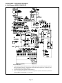
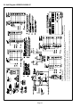
VII−DIAGRAMS / OPERATING SEQUENCE
A− Unit Diagram HSXA15−024/060−2P
Operation Sequence
1 − Cooling demand energizes thermostat terminal Y. Voltage from terminal Y passes through the low pressure
switch, (the timed−off control on −1 units), the high pressure switch and energizes the K1 compressor contactor coil (provided 5−minute delay is satisfied).
2−
K1 closes energizing B1 compressor and B4 outdoor fan.
3−
When cooling demand is satisfied, K1 opens and de−energizes the compressor and outdoor fan. (The timed
off control begins a 5−minute delay on −1 units only).
Page 15
Operating Sequence
/
/
Page 16
3 − When cooling demand is satisfied, K1 opens and de−energizing the compressor and outdoor fan.
2 − K1 closes energizing B1 compressor and B4 outdoor fan.
1 − Cooling demand energizes thermostat terminal Y. Voltage from terminal Y passes through S87 low pressure
switch, S4 high pressure switch and energizes K1 compressor contactor coil.
B− Unit Diagram HSXB15−024/060−1P