1
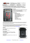
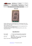
Documnent/File name
Document Type
MANTTT802LE.docx
External
First Revision, Sign and Date
Updated Revision, Sign and Date
Document Status and Sign
Bln 2009-03-29
Bln 2010-04-20
Approved by Lan
Revision
3
Page
1 (4)
Document and Product Description
User Manual TTT802 Gearshift Controller – Spec(L) Firmware
TTT802 Gearshift Controller
Part # 12-620-9
Overview:
Gearshift Controller for 4 or 5 speed sequential operated
gearboxes. With 58 mm large red gear indicator display and
Rpm / shift-light-bar with green, yellow, red white Led lamps.
Key features:
-
Gear Position Indicator
Rpm / Shift-light Led-bar
Closed Loop Flat-shift control
Measuring Gearshift times in 1/1000 sec.
Measuring Gearbox Race time
Rpm limiter
Launch control
Automatic display intensity
Special functions on request
Built in computer port gives easy access to all parameters for
flat-shift and Rpm limiter as well as other functions such as
measured gear change times, gearbox running time, shift
counter etc. We supply an easy to use Windows-application
that supports all these functions. The installation of the
program is done thru our website www.ttt-racing.com
Order # 12-620-9-L
Spec(L) Firmware
The system is completely controlled by the 3 sensors,
“Lever”, “Neutral” and “Gear Change” and there is no need for
any calibration.
Housing:
Black anodized aluminium with polycarbonate front panel
Size:
65 x 110 x 30 mm
Weight:
220 grams
Power Supply:
12-14 Volt DC, Average current 100mA (max. 300mA)
Fuse:
Recommended fuse 0,5 – Max. 1 Amp must be installed
In the power supply line
Connections:
There are 2 connectors located on the rear, one 16 pole, A,
and one 22 pole, B.
www.ttt-racing.com
TTT Racing Products, Sweden
www.flatshift.com
Documnent/File name
Document Type
MANTTT802LE.docx
External
First Revision, Sign and Date
Updated Revision, Sign and Date
Document Status and Sign
Bln 2009-03-29
Bln 2010-04-20
Approved by Lan
Revision
3
Page
2 (4)
Document and Product Description
User Manual TTT802 Gearshift Controller – Spec(L) Firmware
Functions:
Gear Pos Indicator
The sensors are continuously sensed and the controller converts the reading into gear in position. The
7 different possible positions are R - N - 1 - 2 - 3 - 4 - 5. Up until the N sensor has been detected for
the first time after power on the display indicates “ –“.
Rpm- / Shift-light Bar
By measuring the connected ignition pulses the rpm is calculated and compared to the settings for
each level of the bar. The result of the comparison controls how many Leds are lit. The setting for
each bar level can be individually entered for each gear position. It is possible to chose between 3
different “bar types”. One dot from left & right, two dots from left & right or the default one, fill from left
& right.
Rpm Limiter
The Gearshift Controller limits the rpm to the maximum allowed rpm corresponding to the setting for
the particular gear position. The maximum rpm setting can be individually entered for each gear
position.
Launch Control
st
Holding down the Start switch being in 1 gear position limits the rpm to a preset start value. By
connecting a Start Rpm limit adjust potentiometer it can then be used to increase or decrease the
actual start rpm limit. When the Start switch is released the allowed rpm increases with time until it has
st
reach the rpm limit setting for 1 gear. How fast it increases depends on the start ramp time setting.
By connecting a Ramp time adjust potentiometer it can then be used to increase or decrease the
actual start ramp time. The “Quick Trim” unit with part # 12-660-5 have 2 potentiometers and can be
directly connected to the cable harness if the harness is complemented with the QT cable harness
“addon”, part # 12-639-9.
Firmware 1.3: The positions of the Launch Control potentiometers are indicated on the Rpm-bar while
they are adjusted. At the same time the Gear Pos Indicator displays a small “T” when the Ramp time
is adjusted and a “^” is displayed when the Start Rpm limit is adjusted.
Closed Loop Flat-shift Control
The 3 main sensors used by the control continuously informs the controller about any attempt to
change gear. When the controller detects a beginning shift-up it manipulates the ignition pulses and
they are not completely activated again until we are in a safe position to do so. There are user settings
to enable/disable shift-up gear cut on each gear to customize the function to specific ideas and needs.
Thanks to the closed loop system the driver can shift fast or slow, just the way he likes, which is a big
advantage compared to more simple timing controlled flat-shift systems. Shifting fast really means
fast.
Firmware 1.3: In the Windows program TTT802L Manager the user can chose if the Gear Pos
Indicators decimal dot should indicate the flatshift “cut” of the ignition.
There is a choice of using an analog Lever sensor and if so turning this on and setting up the limit for
the sensor etc. is done in the Windows program TTT802L Manager.
Gear Shift counter
Firmware 1.3: The total number of gear shift up, gear 1, 2, 3, 4, (5) is counted and can be read and
cleared using the Windows program TTT802L Manager.
Gear Shift time measurement
Firmware 1.3: The shortest Gear Shift time in 1/1000 sec. between each gear, gearing up and down,
is measured and can be read and cleared using the Windows program TTT802L Manager.
www.ttt-racing.com
TTT Racing Products, Sweden
www.flatshift.com
Documnent/File name
Document Type
MANTTT802LE.docx
External
First Revision, Sign and Date
Updated Revision, Sign and Date
Document Status and Sign
Bln 2009-03-29
Bln 2010-04-20
Approved by Lan
Revision
3
Page
3 (4)
Document and Product Description
User Manual TTT802 Gearshift Controller – Spec(L) Firmware
Gearbox race time
Firmware 1.3: The race time in gear 1, 2, 3, 4, (5), total and on each gear, are measured and can be
read and cleared using the Windows program TTT802L Manager.
Display test / Show Firmware version
Firmware 1.3: When the TTT802L is powered up the display shows “V” “1” “.” “3” (if firmware = 1.3)
and then the display and bar segments are toggled for aprox. 4 second. If there is Rpm input and the
gear position is not “N” the display test will be bypassed.
Oil change Interval
Firmware 1.3: During the first 10-15 seconds after the TTT802L has been powered up the “N” for
Neutral position will be replaced with a “0” if the Oil change interval has been reached. The interval
can be setup and the oil change confirmed using the Windows program TTT802L Manager.
Function test Sensors:
Testing the Gearbox sensor function - “Lever”, “Neutral” & “Gear Change”
To initiate the test procedure just “wave” with a magnet in front of the rpm / shift-light bar. By doing so
the display will indicate the status of the 3 sensors and the dot will flash. The “mid” position indicates
the “Neutral”, the “top” position indicates the “Gear Change” and the “bottom” position indicates the
“Lever” sensor. “Wave” again to turn off the function test.
Note: The Lever sensor has a safety time and if the sensor is active for a longer period than this time,
the sensor will indicate off even if its on. The safety time is normally set to 1 sec.
Related products.
Part # 12-645-2
Part # 12-627-2
Part # 12-639-9
Part # 12-649-8
Part # 12-650-6
Part # 12-660-5
Part # 12-671-3
Part # 12-678-6
Part # 30-515-6
Part # 30-521-9
TTT802 Cable harness type L
TTT802 Cable kit with ”flying wires”
TTT802-QT Cable harness ”add-on” for startrswitch and Quick Trim unit
Communication cable RS232 for TTT802. 1,5m.
Extension cable 500mm 4-pole DR25.
TTT905 Quick Trim unit (Launch Control)
TTT748 Ignition Interface (for carburettor motors with Hal-sensor
distributors)
TTT937 Power Switch, Ignition cut when used with ECU without cut
input. Interrupts ignition coil power (Vbat)
N-sensor and Gear Change sensor
Gear Lever sensor.
www.ttt-racing.com
TTT Racing Products, Sweden
www.flatshift.com
Documnent/File name
Document Type
Revision
MANTTT802LE.docx
External
First Revision, Sign and Date
Updated Revision, Sign and Date
Document Status and Sign
Bln 2009-03-29
Bln 2010-04-20
Approved by Lan
3
Page
4 (4)
Document and Product Description
User Manual TTT802 Gearshift Controller – Spec(L) Firmware
Connections:
A - 16-pole Matching Connector, Molex Microfit 3,0 430251600
A:1
Ground, PC Com interface
A:2
Tx, PC Com interface RS232 level – Transmit data
A:3
Rx, PC Com interface RS232 level – Receive data
A:4
DO1, Digital FET output, 0 – 12 VDC, RPM-out Ignition pulses to RPM-meter
A:5
DI1, Ground
A:6
DI1, Digital input 5 - 15VDC Ignition Pulse
A:7
DO2, Galvanic Isolated ground for output ECU/Ignition Cut
A:8
DO2, Galvanic Isolated output, open collector, for ECU/Ignition Cut
A:9
DO5, Ground
A:10
DO5, Digital FET output, active low (Spare)
A:11
DO4, Ground
A:12
DO4, Digital FET output, active low (Spare)
A:13
DO3, Ground
A:14
DO3, Digital FET output, active low (Spare)
A:15
Powersupply (Ground)
A:16
Powersupply 12 VDC (+) Note!!! Fuse 0,5 – Max.1 Amp. must be installed in the
powerline
B – 22-pole Matching Connector, Molex Microfit 3,0 430252200
B:1
DI5, DI6, DI7 (Gnd)
B:2 (*)
DI7, Digital input 12VDC (Spare)
B:3 (*)
DI6, Digital input 12 VDC Speed sensor
B:4
DI5, Digital input 12 VDC Gear Lever sensor
B:5 (*)
12 VDC for sensors and switches
B:6 (*)
12 VDC for sensors and switches
B:7 (*)
DI4, Digital input 12VDC N-R-Interlock / Start switch
B:8
DI3, Digital input 12VDC Gear Change sensor
B:9
DI2, DI3, DI4, Ground
B:10
DI2, Digital input 12VDC Neutral sensor
B:11
AI4, Analog Ground
B:12
AI4, +5VDC
B:13
AI3, Analog Ground
B:14
AI4, Analog input Start Ramp time adjust potentiometer
B:15
AI3, +5VDC
B:16
AI3, Analog input Start Rpm limit adjust potentiometer
B:17
AI2, Analog Ground
B:18
AI2, Analog input (Spare / Analog Lever sensor)
B:19
AI2, +5VDC
B:20
AI1, Analog input (Spare)
B:21
AI1, Analog Ground
B:22
AI1, +5VDC
(DI6 input on prototypes)
(Gnd on prototypes)
(Gnd on prototypes)
(DI4 input on prototypes)
(Gnd on prototypes)
(*) Different functions compared to prototype units!!!
www.ttt-racing.com
TTT Racing Products, Sweden
www.flatshift.com