1
UEIModbus User Manual
UEIModbus User Manual 2.1
February 2013 Edition
© Copyright 2013 United Electronic Industries, Inc. All rights reserved
No part of this publication may be reproduced, stored in a retrieval system, or transmitted, in any form by any means,
electronic, mechanical, by photocopying, recording, or otherwise without prior written permission.
1
UEIModbus User Manual
Table of contents
1. Introduction ............................................................................................ 3
1.1.
Register tables ..................................................................................................... 3
1.2.
Mapping of PowerDNA I/O layers to MODBUS register tables. ...................... 4
1.2.1.
Digital device representation ...................................................................... 4
1.2.2.
Analog device representation ...................................................................... 5
2. Configuring the UEIModbus from the command line ....................... 6
2.1.
Connecting through the serial port ...................................................................... 6
2.2.
Configuring the IP address.................................................................................. 7
2.3.
Starting/Stopping MODBUS slave service ......................................................... 7
2.4.
Configuring I/O channels .................................................................................... 8
2.4.1.
Configuring an analog input device ............................................................ 8
2.4.2.
Configuring an analog output device .......................................................... 9
2.4.3.
Configuring a digital input device ............................................................ 10
2.4.4.
Configuring a digital output device .......................................................... 10
3. UEIModbus configuration GUI .......................................................... 13
3.1.
3.2.
3.3.
Configure IP address ......................................................................................... 14
Configuring I/O channels .................................................................................. 16
Test I/O channels .............................................................................................. 17
2
UEIModbus User Manual
1. Introduction
MODBUS is a messaging protocol developed by Modicon in 1979, used to establish
master-slave/client-server communication between intelligent devices. It is a de facto
standard, truly open, and the most widely used network protocol in the industrial
manufacturing environment. (Specifications available at http://www.modbus-ida.org).
MODBUS devices communicate using a master-slave technique in which only one
device (the master) can initiate transactions (called queries). The other devices (slaves)
respond by supplying the requested data to the master, or by taking the action requested
in the query.
A slave is any peripheral device (I/O transducer, valve, network drive, or other measuring
device), which processes information and sends its output to the master using MODBUS.
Masters can address individual slaves, or can initiate a broadcast message to all slaves.
Slaves return a response to all queries addressed to them individually, but do not respond
to broadcast queries.
UEIModbus extends the capability of the PowerDNA distributed data acquisition system
by turning it into a MODBUS/TCP slave that can be accessed by any software client that
can act as a MODBUS/TCP master. Most popular HMI software packages support the
MODBUS/TCP protocol.
1.1.
Register tables
The MODBUS specification defines four register tables (or register maps) in which I/Os
can be read or written.
Register
table
0xxxx
1xxxx
3xxxx
4xxxx
Classic Name
Description
Coils
(Read/Write)
Discrete
Inputs (Readonly)
Input
Registers
(Read-only)
Holding
Registers
(Read/Write)
A 0x reference address is used to drive
output data to a digital output channel.
Read Discrete Inputs. The ON/OFF status
of a 1x reference address is controlled by
the corresponding digital input channel.
A 3x reference register contains a 16-bit
number received from an external source
like an analog input signal.
A 4x register is used to store 16-bits of
numerical data (binary or decimal), or to
send the data from the CPU to an output
channel.
Data
representation
1 bit
1 bit
16 bits
16 bits
3
UEIModbus User Manual
For each of those tables, the protocol allows a maximum of 65536 data items to be
accessed. It is slave dependent, in which data items are accessible by a master.
Typically, a slave implements only a small memory area.
UEIModbus only implements memory areas big enough to hold the number of channels
used on each layer.
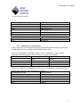
1.2.
Mapping of PowerDNA I/O layers to MODBUS register
tables.
Each PowerDNA I/O layer is addressed using a device number starting with 0 for the top
layer, 1 for the layer below, and so on. This device number is used to calculate the
address of the MODBUS registers associated with each layer by multiplying it by 1000.
Device 0 MODBUS registers will start at address 0
Device 1 MODBUS registers will start at address 1000
…
Device x MODBUS registers will start at address 1000*x
Coils and Discrete Inputs registers can only represent one bit. They are used to hold the
digital output and input line state of digital devices.
Input and Holding registers can represent 16-bit. Each register can represent a digital port
or an analog channel raw value for devices of resolution lesser or equal to 16 bits.
To represent values greater than 16 bits, two Input or Holding registers are needed.
Two registers are also needed to represent the scaled value of analog channels using the
32-bit IEEE floating point representation.
Four registers are needed to represent the scaled values of analog channels using the 64bit IEEE double precision floating point representation.
1.2.1. Digital input/output device representation
Digital I/O devices are always mapped twice:
Each individual line is mapped in the Coil (for output) or Discrete Input(for input)
tables
Each port is mapped in the Holding register (for output) or Input register (for
input) tables.
Here is an example for a 12-bit DI layer at dev. 2.
4
UEIModbus User Manual
Discrete Input table
2001
2002
2003
…
2011
2012
Physical channel
Input port 0 line 0
Input port 0 line 1
Input port 0 line 2
…
Input port 0 line 10
Input port 0 line 11
Input Register table
2001
Physical port
Input port 0
1.2.2. Analog device representation
Analog input devices are mapped in the input register table and the holding register table.
Analog output devices are mapped in the holding register table.
Here is an example for a 16 channels AI layer at dev3 configured to acquire data as
simple precision floating point values (32-bits: two registers per channel):
Input Register table
Holding Register table
Physical channel
3001
3001
channel 0
3003
3003
channel 1
…
…
…
3031
3031
channel 15
Here is an example for an 8 channels AO layer at dev5 configured to use double precision
floating point values (64-bits: 4 registers per channel):
Holding Register table
Physical channel
5001
channel 0
5005
channel 1
…
…
5027
channel 6
5031
channel 7
5
UEIModbus User Manual
2. Configuring the UEIModbus from the command line
You will need to configure the IP address and the I/O channels you wish to make
available to MODBUS/TCP masters.
The IP address must be configured using the serial port.
The I/O channels are configured in the file “/etc/modbusslave.conf”, located on the root
file system.
2.1.
Connecting through the serial port
Connect the serial cable to the serial port on the UEIModbus cube and the serial port on
your PC.
You will need a serial communication program:
Windows: ucon, MTTTY or HyperTerminal.
Linux: minicom or cu (part of the uucp package).
The PowerDNA I/O module uses the serial port settings: 57600 bits/s, 8 data bits, 1 stop
bit and no parity. Run your serial terminal program and configure the serial
communication settings accordingly.
Connect the DC output of the power supply (24VDC) to the “Power In” connector on the
PowerDNA cube and connect the AC input on the power supply to an AC power source.
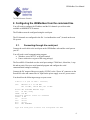
You should see the following message on your screen:
U-Boot 1.1.4 (Jan 10 2006 - 19:20:03)
CPU:
MPC5200 v1.2 at 396 MHz
Bus 132 MHz, IPB 66 MHz, PCI 33 MHz
Board: UEI PowerDNA MPC5200 Layer
I2C:
85 kHz, ready
DRAM: 128 MB
Reserving 349k for U-Boot at: 07fa8000
FLASH: 4 MB
In:
serial
Out:
serial
Err:
serial
Net:
FEC ETHERNET
Type "run flash_nfs" to mount root filesystem over NFS
6
UEIModbus User Manual
Hit any key to stop autoboot:
5
## Booting image at ffc10000 ...
Image Name:
Linux-2.6.16.1
Created:
2006-11-10 16:07:06 UTC
Image Type:
PowerPC Linux Kernel Image (gzip compressed)
Data Size:
917636 Bytes = 896.1 kB
Load Address: 00000000
Entry Point: 00000000
Verifying Checksum ... OK
Uncompressing Kernel Image ... OK
id mach(): done
...
< lots of kernel messages >
...
BusyBox v1.2.2 (2006.11.03-19:16+0000) Built-in shell (ash)
Enter 'help' for a list of built-in commands.
~ #
You can now navigate the file system and enter standard Linux commands such as ls, ps,
cd…
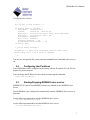
2.2.
Configuring the IP address
Your UEIModbus cube is configured at the factory with the IP address 192.168.100.2 to
be part of a private network.
You can change the IP address for the current session using the command:
setip <new IP address>
2.3.
Starting/Stopping MODBUS slave service
MODBUS/TCP request from MODBUS masters are handled by the MODBUS slave
service.
The UEIModbus is pre-configured to automatically start the MODBUS slave service at
boot time.
Use the following command to stop the MODBUS slave service:
/etc/init.d/modbusslave stop
Use the following command to start the MODBUS slave service:
/etc/init.d/modbusslave start
7
UEIModbus User Manual
Use the following command to restart the MODBUS slave service:
/etc/init.d/modbusslave restart
Use the following command to disable automatic start of MODBUS slave service:
mv /etc/rc.d/S40modbusslave /etc/rc.d/K40modbusslave
Use the following command to enable automatic start of MODBUS slave service:
mv /etc/rc.d/K40modbusslave /etc/rc.d/S40modbusslave
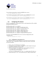
2.4.
Configuring I/O channels
The file /etc/modbusslave.conf describes the devices and channels that will be available
through the MODBUS protocol.
Each line starting with ‘#’ is a comment.
Each line starting with “AI” configures an analog input device.
Each line starting with “AO” configures an analog output device.
Each line starting with “DI” configures a digital input device.
Each line starting with “DO” configures a digital output device.
Each line starting with “CI” configures a counter input device.
Each line starting with “CO” configures a frequency/PWM output device
You must re-start the MODBUS slave service to activate changes made to the
configuration file:
/etc/init.d/modbusslave restart
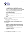
2.4.1. Configuring an analog input device
The configuration line for an analog input device can contain any of the following
“name=value” pairs. If a parameter is omitted, a default value will be used instead.
It is not case sensitive.
Device={X}: the id of the device to configure.
NumChannels={X}: the number of channels to use (first channel is always 0).
InputMode={DIFF|RSE}: the input mode
Gain={X}: the gain, “0” for gain of 1, “1” for next higher gain and so on.
For example AI-207 comes with the following gains:
1,2,4,8,10,20,40,80,100,200,400,800.
Set Gain=6 to configure gain of 40, Gain =7 to configure gain of 80 and so on.
MeasurementType={V|TC}: the measurement type, voltage or thermocouple.
8
UEIModbus User Manual
TCType={E|J|K|S|R|T|B|N|C}: the thermocouple type.
TempScale={C|F|K}: the temperature scale, Celsius, Fahrenheit or Kelvin.
CJCType={BUILTIN|CONSTANT}: the cold-junction compensation type.
“BUILTIN” uses the sensor on the terminal panel, “CONSTANT” uses a constant
value.
CJCConst={X}: the cold-junction compensation temperature to use when
CJCType is set to “CONSTANT”.
DataType={i16|i32|swi32|f32|swf32|f64|swf64}: The data type used to transmit
values between the slave and the master.
f32: single-precision floating point
swf32: single-precision floating point. Upper 16-bits and lower 16-bits are
swapped
f64: double precision floating point.
swf64: double precision floating point. Upper 32-bits and lower 32-bits are
swapped
The following example configures device 2 to acquire temperatures on its first 4 channels
(don’t wrap the line when typing it):
AI device=2 numChannels=4 inputMode=DIFF gain=8 measurementType=TC
TCType=K tempScale=C CJCType=BUILTIN dataType=f32
2.4.2. Configuring an analog output device
The configuration line for an analog output device can contain any of the following
“name=value” pairs. If a parameter is omitted, a default value will be used instead.
It is not case sensitive.
Device={X}: the id of the device to configure.
NumChannels={X}: the number of channels to use (first channel is always 0).
DataType={i16|i32|swi32|f32|swf32|f64|swf64}: The data type used to transmit
values between the master and the slave.
f32: single-precision floating point
swf32: single-precision floating point. Upper 16-bits and lower 16-bits are
swapped
f64: double precision floating point.
swf64: double precision floating point. Upper 32-bits and lower 32-bits are
swapped
The following example configures device 0 to generate on its first 4 channels:
AO device=0 numChannels=4 dataType=f32
9
UEIModbus User Manual
2.4.3. Configuring a digital input device
The configuration line for a digital input device can contain any of the following
“name=value” pairs. If a parameter is omitted, a default value will be used instead.
It is not case sensitive.
Device={X}: the id of the device to configure.
NumChannels={X}: the number of ports to use (first port is always 0).
DataType={i16|i32|swi32|f32|swf32|f64|swf64}: The data type used to transmit
values between the slave and the master.
i16: 16-bits integer
i32: 32-bits integer
swi32: swapped 32-bits integer. Upper 16-bits and lower 16-bits are swapped
The following example configures device 5 to acquire digital signals on its first port:
DI device=5 numChannels=1 dataType=i32
2.4.4. Configuring a digital output device
The configuration line for a digital output device can contain any of the following
“name=value” pairs. If a parameter is omitted, a default value will be used instead.
It is not case sensitive.
Device={X}: the id of the device to configure.
NumChannels={X}: the number of ports to use (first port is always 0).
DataType={i16|i32|swi32|f32|swf32|f64|swf64}: The data type used to transmit
values between the master and the slave.
i16: 16-bits integer
i32: 32-bits integer
swi32: swapped 32-bits integer. Upper 16-bits and lower 16-bits are swapped
The following example configures device 1 to generate digital patterns on its first port:
DO device=1 numChannels=1 dataType=i32
2.4.5. Configuring a counter input device
The configuration line for a counter input device can contain any of the following
“name=value” pairs. If a parameter is omitted, a default value will be used instead.
It is not case sensitive.
Device={X}: the id of the device to configure.
NumChannels={X}: the number of counters/ports to use (first port is always 0).
10
UEIModbus User Manual
DataType={i16|i32|swi32|f32|swf32|f64|swf64}: The data type used to transmit
values between the slave and the master.
i16: 16-bits integer
i32: 32-bits integer
swi32: swapped 32-bits integer. Upper 16-bits and lower 16-bits are swapped
Mode={count|quad|period|pulsewidth}: The mode used to configure the counter
to measure events, quadrature encoder position, period or pulse width
Source={internal|external}: The source signal to count or measure, internal uses
the on-board 66MHz clock, external uses the signal connected to the counter’s
input pin.
Gate={internal|external}: The gate signal to enable/disable the counter, internal
sets the gate automatically when counter starts, external uses a signal connected to
the counter’s gate pin.
InputInverted={0|1}: Set to 1 to invert the input signal.
The following example configures device 2 to measure quadrature encoders position
connected to ports 0,1,2,3:
CI device=2 numChannels=4 dataType=i32 mode=quad source=external
gate=internal inputinverted=0
2.4.6. Configuring a frequency/PWM output device
The configuration line for a frequency output device can contain any of the following
“name=value” pairs. If a parameter is omitted, a default value will be used instead.
It is not case sensitive.
Device={X}: the id of the device to configure.
NumChannels={X}: the number of counters/ports to use (first port is always 0).
DataType={i16|i32|swi32|f32|swf32|f64|swf64}: The data type used to transmit
values between the master and the slave.
i16: 16-bits integer
i32: 32-bits integer
swi32: swapped 32-bits integer. Upper 16-bits and lower 16-bits are swapped
Mode={pulse|train}: The mode used to configure the counter to output pulse(s),
“pulse” will output a single pulse each time a new value is written to the Modbus
register. “train” will continuously output pulses.
lowticks={X}: The initial number of clock ticks used to specify the low state
duration.
highticks={X}: The initial number of clock ticks used to specify the high state
duration.
11
UEIModbus User Manual
The following example configures device 2 to output pulses out of ports 0,1,2,3:
CO device=2 numChannels=4 dataType=i32 mode=train lowticks=1000
highticks=1000
12
UEIModbus User Manual
3. UEIModbus configuration GUI
The UEIModbusConf provides a GUI to ease configuration and test of the UEIModbus.
Connect the serial cable to the serial port on the UEIModbus cube and the serial
port on your PC.
Connect the DC output of the power supply (24VDC) to the “Power In” connector
on the PowerDNA cube and connect the AC input on the power supply to an AC
power source.
Run the UEIModbusConf.exe program
13
UEIModbus User Manual
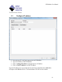
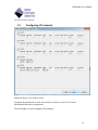
3.1.
Configure IP address
Select the host PC serial port connected to the UEIModbus
Type the IP address of the UEIModbus
Click on Change IP Address to program the new IP address
Click on Test IP Address to test the IP address
Once the IP address test is successful, the list of I/O layers installed in the UEIModbus
will appear in the Devices list box. The button Next> will also become enabled.
14
UEIModbus User Manual
15
UEIModbus User Manual
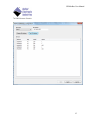
3.2.
Configuring I/O channels
Enable the devices you wish to access.
Configure the parameters for each selected device. Refer to section 2.4 for more
informations about device parameters
Click on Next> to test the configured I/O channels
16
UEIModbus User Manual
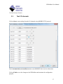
3.3.
Test I/O channels
Click on Start to start reading from the I/O channels using MODBUS/TCP protocol.
Check Automatically start modbus server to start MODBUS slave service at boot time.
Click on Finish to save the changes to the UEIModbus and terminate the configuration
program.
17