1
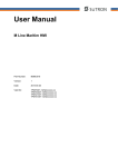
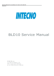
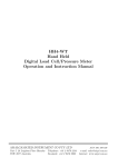
1601
Temperature Controller
r USER'S MANUAL
Issue date
March 2000
1601-0-0C.p65
0037 - 75236
1
5/2/00, 1:45 PM
CONTENTS
OUTLINE AND CUT OUT DIMENSIONS .......... III
MOUNTING REQUIREMENTS .......................... 1
CONNECTION DIAGRAMS ................................ 2
GENERAL OPERATION ..................................... 5
CONFIGURATION HARDWARE SETTINGS ..... 5
CONFIGURATION PARAMETERS .................... 6
OPERATOR MODE .......................................... 10
Indicators ................................................... 10
Pushbutton function ................................... 11
Manual reset of the alarms ......................... 11
SMART algorithm ...................................... 11
Output power OFF ..................................... 12
Direct access to the set point ..................... 12
Display of the set point value ..................... 12
Bargraph operating .................................... 13
Lamp test ................................................... 13
OPERATOR PARAMETERS ............................ 13
ERROR MESSAGES ........................................ 15
GENERAL INFORMATIONS ............................ 17
MAINTENANCE ................................................ 18
DEFAULT PARAMETERS ............................... A.1
II
1601-0-0C.p65
2
5/2/00, 1:45 PM
Model identification
Model
1601
1/16 DIN Temperature Controller, Single Display
Code
Output 1 - Heat or Cool
1
Relay, 3 Amps at 250 Vac (Resistive)
6
SSR Drive, 14 Vdc at 20 mA
Code
1
Output 2 - Alarm
Relay, 1 Amp at 250 Vac (Resistive load)
Code
0
Add to complete model number
Code
Instrument Power
3
100 - 240 Vac
5
24 Vac/dc
Code
1601
6
1
0
3
0
Add to complete model number
0
Typical Model Number
IV
1601-0-0C.p65
3
5/2/00, 1:45 PM
OUTLINE AND CUT OUT DIMENSIONS
V
1601-0-0C.p65
4
5/2/00, 1:45 PM
VI
1601-0-0C.p65
5
5/2/00, 1:45 PM
Screw
MOUNTING REQUIREMENTS
Select a mounting location where there is
minimum vibration and the ambient temperature
range between 0 and 50 °C (32 and 122 °F).
The instrument can be mounted on a panel up to
15 mm thick with a square cutout of 45 x 45 mm.
For outline and cutout dimensions refer to page IV.
The surface texture of the panel must be better
than 6.3 mm.
The instrument is shipped with rubber panel
gasket.
To assure the IP65 and NEMA 4 protection, insert
the panel gasket between the instrument and the
panel as show in fig. 1.
While holding the instrument against the panel
proceed as follows:
1) insert the gasket in the instrument case;
2) insert the instrument in the panel cutout;
3) pushing the instrument against the panel, insert
the mounting bracket;
4) with a screwdriver, turn the screws with a
torque between 2.7 to 3.5 in-lb (0.3 and 0.4
Nm).
bracket
Panel
Gasket
Fig. 1
1
1601-1-0C.p65
1
5/2/00, 1:45 PM
A) MEASURING INPUTS
NOTE: Any external components (like zener
barriers etc.) connected between sensor and input
terminals may cause errors in measurement due
to excessive and/or not balanced line resistance or
possible leakage currents.
CONNECTION DIAGRAMS
Connections are to be made with the instrument
housing installed in its proper location.
TC INPUT
+ 3
_ 2
Shield
+ 3
_ 2
Shield
Fig. 4 THERMOCOUPLE INPUT WIRING
NOTE:
1) Don’t run input wires together with power
cables.
2) For TC wiring use proper compensating cable
(for example, J TC extension wire for J TC)
preferable shielded.
3) when a shielded cable is used, it should be
connected at one point only.
Fig. 2 REAR TERMINAL BLOCK
2
1601-1-0C.p65
2
5/2/00, 1:45 PM
RTD INPUT
B) RELAY OUTPUTS
RTD
RTD
6
OUT 1
7
8
OUT 2
1
2
3
1
2
5
3
4
Fig. 5 RTD INPUT WIRING
NO
C
NO
NOTES 1) To avoid electric shock, connect power
line at the end of the wiring procedure.
2) For power connections use No 16 AWG
or larger wires rated for at last 75 °C
(167°F).
3) Use copper conductors only.
4) Don’t run input wires together with power
cables.
The following recommendations avoid serious
problems which may occur, when using relay
output for driving inductive loads.
3
3
C
Fig. 6 RELAY OUTPUT WIRING
The OUT 1 NO contact and the OUT 2 contact are
protected by varistor against inductive load with
inductive component up to 0.5 A.
The contact rating of the OUT 1 is 3A/250V AC on
resistive load.
The contact rating of the OUT 2 is 1A/250V AC on
resistive load.
The number of operations is 1 x 10⁵ at specified
rating.
NOTE:
1) Don’t run input wires together with power
cables.
2) Pay attention to the line resistance; a high line
resistance may cause measurement errors.
3) When shielded cable is used, it should be
grounded at one side only to avoid ground loop
currents.
4) The resistance of the 3 wires must be the
same. Use the same gauge wire for all three
conductors.
1601-1-0C.p65
NC
5/2/00, 1:45 PM
INDUCTIVE LOADS
High voltage transients may occur when switching
inductive loads.
Through the internal contacts these transients may
introduce disturbances which can affect the
performance of the instrument.
The internal protection (varistor) assures a correct
protection up to 0.5 A of inductive component but
the OUT 1 NC contact is not protected.
The same problem may occur when a switch is
used in series with the internal contacts as shown
in Fig. 7.
VOLTAGE OUTPUTS FOR SSR DRIVE
+
8
OUT 1
SOLID STATE
RELAY
Fig. 8 SSR DRIVE OUTPUT WIRING
It is a time proportioning output.
Logic level 0: Vout < 0.5 V DC.
Logic level 1:
- 14 V + 20 % @ 20 mA
- 24 V + 20 % @ 1 mA.
Maximum current = 20 mA.
NOTE: This output is not isolated.
A double or reinforced Isolation between instrument
output and power supply must be provided by the
external solid state relay.
POWER
LINE
LOAD
Fig. 7 EXTERNAL SWITCH IN SERIES WITH
THE INTERNAL CONTACT
In this cases it is recommended to install an
additional RC network across the external contact
as show in Fig. 7 (Chromalox snubber PN 014901305 is recommended).
The value of capacitor (C) and resistor (R) are
shown in the following table.
R
(W)
P.
(W)
OPERATING
VOLTAGE
<40 mA 0.047 100
0.1
22
<150 mA
0.33 47
<0.5 A
1/2
2
2
260 V AC
260 V AC
260 V AC
LOAD
(mA)
C
(mF)
Anyway the cable involved in relay output wiring
must be as far away as possible from input or
communication cables.
4
1601-1-0C.p65
4
+
_
7
R
C
_
5/2/00, 1:45 PM
A) POWER LINE WIRING
GENERAL OPERATION
Theree are two setup modes for the 1601
- Configuration mode
- Operator mode
In general the configuration mode is the initial
setup of the controller when first installed. Input
type and alarm setup are examples of Configuration mode setting. The operator mode includes
settings that might be adjusted frequently with
daily control operations such as set points and PID
parameters.
N
N
Fig. 3 POWER LINE WIRING
CONFIGURATION MODE
NOTE:
1) Before connecting the instrument to the power
line, make sure that line voltage corresponds to
the description on the identification label.
2) To avoid electric shock, connect power line at the
end of the wiring procedure.
3) For supply connections use No 16 AWG or larger
wires rated for at last 75 °C (167°F).
4) Use copper conductors only.
5) Don’t run input wires together with power cables.
6) For 24 V AC/DC the polarity is not important.
7) The power supply input has NO fuse protection.
Please, provide externally a T type 1A, 250 V fuse.
8) The safety requirements for Permanently Connected Equipment are:
- a switch or circuit-breaker shall be included in the
building installation;
- It shall be in close proximity to the equipment and
within easy reach of the operator;
- it shall be marked as the disconnecting device for
the equipment.
NOTE: a single switch or circuit-breaker can drive
more than one instrument.
PRELIMINARY HARDWARE
SETTINGS FOR CONFIGURATION
1) Remove the instrument from its case.
V2
L3
C5
C6
C7
C10
PZ1
L2
C8
R8
R (S,T)
R (S,T)
B
+
9
POWER LINE
100 V to 240 V AC (50/60Hz)
or 24 V AC/DC
+
10
5
L4
C9
R7
C14
J6
V2
PZ3
C2
1 J5
R4
2
2
R5
K2
3
4
PZ4
Q2
R3
C15
R11
PZ5
2) Set the internal switch V2 in open condition
5
1601-1-0C.p65
PZ2
5/2/00, 1:45 PM
3) If, during configuration procedure, a °C range
has been selected, it is necessary to put the °C
label on the front of the instrument covering the °F
indication. The sticker is located with the gasket in
the shipping box.
CONFIGURATION PARAMETERS
P1 - Input type and standard range
0 = TC type L
range
0 / +800 °C
1 = TC type J
range
0 / +800 °C
2 = TC type K
range
0 / +999 °C
3 = TC type N
range
0 / +999 °C
4 = RTD type Pt 100 range
-199 / +500 °C
5 = RTD type Pt 100 range
-19.9 /+99.9 °C
6 = TCtype
T
range
0 / +400 °C
8 = TC type L
range
0 / +999 °F
9 = TC type J
range
0 / +999 °F
10 = TC type K
range
0 / +999 °F
11 = TC type N
range
0 / +999 °F
12 = RTD type Pt 100 range
-199 / +999 °F
13 = TC type T
range
0 / +752 °F
NOTE: setting a readout with °F as engineering
unit it is necessary to put on the front of the
instrument, the additional label located in the
“INDEX” of this manual.
°C
4) Re-insert the instrument.
6) Power the instrument “ON”.
The display will show CnF.
NOTE : If “CAL” indication is displayed, press
immediately the s pushbutton to return to
the configuration procedure.
7) Push the FUNC pushbutton.
The parameter code and its value are shown
alternately on the display.
P2 = Initial scale value
Not present when P1 = 5
Insert the initial and full scale values which are
going to be used by the PID algorithm to calculate
the input span.
Puscbutton functionality during
configuration procedure.
FUNC = Must be pressed to store the new value
of a selected parameter and increments to the next parameter.
SMART= in configuration mode, scrolls
parameters back (in reverse order)
without storing the new parameter
value.
s
= increases the value of the selected
parameter
t
= decreases the value of the selected
parameter.
P3 = Full scale value
Not present when P1 = 5
Insert the initial and full scale values which are
going to be used by the PID algorithm to calculate
the input span.
NOTES:
1) the minimum input span (P3 - P2) is 300 °C or
600 °F for TC input and 100 °C or 200 °F for
RTD input.
2) Changing P2 and/or P3 parameters, the rL and
rH parameters will be realligned to it.
6
1601-1-0C.p65
6
5/2/00, 1:45 PM
P4 = Main output action
r = reverse action (heating)
d = direct action (cooling)
Reverse
P7 = Alarm action
Available only when P5 is different from 0 or 4.
r = reverse (relay de-energized in alarm condition)
d = direct (relay energized in alarm condition)
Direct
INPUT
P8 = Alarm inhibit
Present only when P5 is different from 0 or 4.
OFF = inhibit disabled
ON = inhibit enabled
NOTE: If the alarm is programmed as band or
deviation alarm, this function disables the alarm
condition after a set point change or at the
controller startup until the process variable passes
the alarm set point plus or minus hysteresis. If the
alarm is programmed as process alarm, this
function disables the alarm condition at controller
start up until the process variable pass the alarm
set point plus hysteresis.
INPUT
t
OUTPUT
t
OUTPUT
t
t
P5 = Output 2 functions
0 = Not provided
1 = Process alarm
2 = Band alarm
3 = Deviation alarm
4 = instrument failure indicator (under or over
range, CJC, or A-D converter failure)
P9 = OFFSET applied to the measured value
This OFFSET is applied along the whole range.
When P1= 5
P9 is programmable from -19.9
to 19.9 °C.
When P1 ¹ 5
P9 is programmable from -199
to 199 °C or °F.
P6 = Output 2 operator mode.
P6 is available only when P5 is different from 0.
When P5 = 1,2 or 3
H.A = high alarm (outside band) with automatic reset
L.A = low alarm (inside band) with automatic reset
H.L= high alarm (outside band) with manual reset
(latching)
L.L= low alarm (inside band) with manual reset
(latching)
Readout
Real curve
adjusted curve
P9
Input
When P5 = 4 the selections H.A and L.A show an
instrument failure indicator with automatic reset while
the H.L and L.L selections show an instrument failure
indicator with manual reset.
7
1601-1-0C.p65
7
5/2/00, 1:45 PM
P12 = Control output maximum rate of rise
Programmable from 1 % to 10 % of the output per
second.
The ramp is applied when the controller changes
the percent of output desired. Above a 10 % the
display will show "InF" meaning that no ramp is
imposed and the output immediatelychanges to
the PID calculated value.
P12 not used if ON/OFF control selected.
P10 = Threshold of the “Soft Start” function.
Enter the threshold value, in °C or °F, for the automatic start of the "Soft Start" function (limiting output
power). If the unit powers up below the threshold
value, the "Soft Start" function is enabled and limits
the power output to "OLH" for "tOL" minutes. "OLH"
and "tOL" are set in operator mode.
P11 = User defined security code
0 = device unlocked. All the parameters can be
modified
1 = device locked. None of the parameters can be
modified except the SP.
2 to 499 = Select the security code. During the
“operator mode”, the “software key”
parameter will show one of the following
figures:
A)
The device is “Unlocked”
and all parameters can be
modified.
To make the device
“Locked” insert a number
different from the “security
code”. Now none of the
parameters can be modified
except the SP.
B)
The device is “locked” and
none of the parameters can
be modified except the SP.
To “Unlock” the device,
insert the “security code”.
500 to 999 = when selecting a security code between
these two numbers, the operation is identical to
a selection from "2 to 499" except that both the
set point and the alarm set point can be modified.
P13 = Not used
ADVANCED CONFIGURATION
The configuration procedure is completed and the
instrument shows " -.-.-. " on both displays.
When it is desired to end the configuration
procedure push the FUNC pushbutton; the display
will show "CnF".
When it is desired to access to the advanced
configuration parameter procede as follows:
1) using s and t pushbutton set to 219.
2) push the FUNC pushbutton.
8
1601-1-0C.p65
8
5/2/00, 1:45 PM
P14 -Display of the operator parameters.
This parameter is available only if P11 is different
from 0.
This parameter allows you to enable/disable the
display of the protected parameters during
"operator mode".
OFF = protected parameters cannot be displayed
ON = protected parameters can be displayed
P20 - Minimum value of integral time settable
by SMART function.
P20 is programmable from 00.1 (10 seconds) to
02.0 (2 minutes).
P21 = Extension of the anti-reset-wind up
Range: from -30 to +30 % of the proportional
band.
NOTE: a positive value encreases the high limit of
the anti-reset-wind up (over set point) while a
negative value decreases the low limit of the antireset-wind up (under set point).
P15 - SMART function enabling/ disabling
0 = The SMART function is disabled
1 = The SMART function enabling/disabling is
NOT protected by the security code (P11).
2 = The SMART function enabling/disabling is
protected by the security code (P11).
The advanced configuration procedure is
completed and the instrument shows " CnF" on
the display.
Pressing the "FUNC" will return the unit to the first
configuration parameter.
P16 - Maximum value of the proportional band
settable by the SMART function
This parameter may be programmed from P17or
P18 value to 99.9.
P17 - Minimum value of the proportional band
settable by the SMART function in heating
control only.
It may be programmed from 1.0% to P16 value.
P18 - Not Available
P19 - Not Available
9
1601-1-0C.p65
9
5/2/00, 1:45 PM
2) The instrument doesn't display all the
parameters.
It selects the parameters in
accordance with:
a) The instrument configuration in
general (see chapter 3),
b) The P14 parameter in particular (see
chapter 3),
c) The proportional band value (see page
4.2).
OPERATOR MODE
PRELIMINARY
To make the instrument operate as a controller the
internal switch V2 located on the input card (see
Fig. 9) must be closed.
It is assumed, at this point, that the instrument has
been correctly configured as detailed in Section 3.
The instrument shows the process value or the set
point value (in this case the SP LED will be
flashing). In order to toggle the indication push the
s pushbutton. (this display condition is defined as
“normal display mode”).
Pressing the FUNC pushbutton it is possible to
scroll all the operator parameters.
Instrument display alternates between parameter
code and its value. During modification, only the
parameter value will be displayed.
To modify a parameter, first select the desired
parameter by the FUNC pushbutton, then set the
new value by s or t pushbuttons. Press FUNC
pushbutton to store the new value and step to the
next parameter.
NOTE: 1) If, during parameter modification, no
pushbutton is pressed for more than
10 seconds, the instrument reverts
automatically to the “normal display
mode” and the new setting of the last
parameter will be lost.
INDICATORS
SMART Flashing when the first part of the
SMART algorithm is active.
Lit when the second part of the SMART
algorithm is active.
OUT
Lit when the OUT 1 is in ON condition.
ALM
Lit when the alarm 1 is in the alarm state.
SP
Flashing when the display shows the
control set point.
10
1601-1-0C.p65
10
5/2/00, 1:45 PM
SMART ALGORITHM
The SMART feature automatically sets the best
control action.
To enable the SMART function, push the SMART
pushbutton for more than 1.5 s, when the
instrument is in normal display mode. The SMART
LED will light continuously or flash according to
the algorithm automatically selected.
When the smart function is enabled, it is possible
to display but not to modify the control parameters
(PB, TI, TD and rC).
When the traditional control (PID) is desired, push
the SMART pushbutton again (for more than 1.5 s)
to turn the "SMART" OFF. The instrument
maintains the "SMART" set of control parameters
but allows parameter modification.
NOTES:
1) The SMART function uses a derivative time equal
to 1/4 of the integral time.
2) The limits of the proportional band set by the
SMART function are programmed by P16, P17
and P18 parameters.
3) The lower limit of the integral time set by
SMART function is programmed by P20
parameter.
4) When ON/OFF control is programmed (PB=0),
the SMART function is disabled.
5) The SMART enabling/disabling can be
protected by the security code (see P15
parameter).
Pushbutton functions:
FUNC = Stores the new value of the selected
parameter and goes to the next
parameter.
SMART = Enables or disables the SMART
function and scrolls back all the
parameters without storing them.
s
= Increases the value of the selected
parameter or toggles the display
between the set point value and the
measured value.
t
= Decreases the value of the selected
parameter.
t + FUNC = Enables/disables the "LAMP TEST"
NOTE: a 10 seconds time out becomes operational during parameter modification.
If, during operator parameter modification, no
pushbutton is pressed for 10 seconds, the
instrument reverts automatically to the “normal
display mode”. The new setting of the last
parameter modified is going to be memorized,
prior to the time out, only if the FUNC pushbutton
was depressed.
MANUAL RESET OF THE ALARMS
If the alarm has been configured as a latched
alarm, the alarm status persists after the alarm
condition disappears.
To reset the alarm, push the FUNC pushbutton
and select the "n.rS" parameter (the display will
show "n.rS" and "OFF"). Using the s and t
pushbuttons select "ON" and push the FUNC
pushbutton again.
The alarm cannot be reset until the alarm
condition has disappeared.
11
1601-1-0C.p65
11
5/2/00, 1:45 PM
OUTPUT POWER OFF
The Output Power OFF feature turns off the
control and alarm output allowing modification of
parameters without affecting the process. With the
output off the 1601 can be used as an indicator.
To turn OFF the output signal, hold the s
pushbutton first and then push FUNC pushbutton.
After maintaining pressure on both of them for
more than 3 seconds, the instrument will show
"OFF" instead of the set point value.
Since the 1601 has only one display, it is possible
to toggle from "OFF" to measured value by
depressing the s pushbutton.
In the output power off condition the alarms are in no
alarm condition (the alarm output status depends on
the type of alarm action programmed) and the parameters can be reviewed and modified.
When it is desired to come back to normal control,
Hold the s pushbutton first and then push the FUNC
pushbutton.
Maintaining pressure on both of them for more
than 3 seconds, the instrument will return in
NORMAL DISPLAY MODE.
NOTES :
1) If the output is turned OFF when the SMART
function was performing the first part of the
algorithm (LED SMART is flashing), the
SMART function will be aborted and when the
instrument comes back to the normal control,
the SMART function will be disabled.
If the output is turned OFF when the SMART
function was performing the second part of the
algorithm (LED SMART is lit), the SMART
function will be stopped and, when the
instrument comes back to the normal control,
the smart function also will be activated.
2) If the instrument is turned OFF with the output
power off function enabled, at the next start up
the instrument will automatically enable this
function again.
DIRECT ACCESS TO THE SET POINT
MODIFICATION
This feature allows the set point value to be
modified without using the FUNC pushbutton.
When direct access to set point modification is
required, proceed as follows:
1) Push, for more than 3 seconds, the s or t
pushbutton; the set point value, will be
displayed and it will start to change.
2) Using the s and t pushbuttons, it is possible
to set the desired value.
3) When the desired value is reached, do not
push any pushbutton for more than 3 second,
the new set point will become operative after
3 seconds.
If, during this procedure, there is no interest in
saving the new value, push the FUNC pushbutton;
the instrument will automatically return to the
normal display mode without having saved the
new set point.
DISPLAY OF THE SET POINT VALUE
To display the programmed set point value push
the s pushbutton.
The display will show the set point value and the
decimal point of the last significant digit will flash
to indicate that the number shown is the set point
value.
To come back to display the measured value,
push the s pushbutton again.
12
1601-1-0C.p65
12
5/2/00, 1:45 PM
LAMP TEST
To verify operation of the display LED, push t
and FUNC together. The instrument LEDs will
flash until the Lamp Test is turned off.
OPERATOR PARAMETERS
The following is a list of all the available control
parameters. Note that some parameters may not
be displayed according to the specific instrument
configuration.
Push the FUNC pushbutton, the 1601 will
alternately show the parameter and its value or the
status (ON or OFF) of the selected parameter.
Using s or t pushbutton it is possible to set the
desired value or the desired status.
By pushing the FUNC pushbutton, the instrument
saves the new value (or the new status) and goes
to the next parameter.
To turn off the Lamp Test, press t and FUNC
together.
No other pushbutton functions are operable during
the Lamp Test.
Param. DESCRIPTION
SP
Set point (in eng. units).
Range: from rL to rH.
n.rS
Manual reset of the alarms.
This parameter is available only when a
latching alarm has been programmed.
Set ON and push the FUNC pusbutton
to reset the alarms.
nnn
Security code for parameter protection.
This parameter is skipped if P11 = 0 or 1
ON = the instrument is in LOCK condition
OFF = the instrument is in UNLOCK condition
When it is desired to switch from LOCK
to UNLOCK condition, set a value equal
to P11 parameter.
When it is desired to switch from
UNLOCK to LOCK condition, set a value
different from P11 parameter.
AL
Alarm set point(in eng. units).
This parameter is present if an alarm is
configured.
13
1601-1-0C.p65
13
5/2/00, 1:45 PM
HSA
Pb
HS
ti
td
Ranges:
- From P2 to P3 for process alarm.
- From 0 to 500 units for band alarm.
- From -199 to 500 units for deviation
alarm.
Alarm hysteresis (in % of P3 - P2 span)
This parameter is present if an alarm is
configured.
Range:From 0.1% to 10.0% of the input
span or 1 LSD.
Note: If the hysteresis of a band alarm is
larger than the alarm band, the
instrument will use an hysteresis value
equal to the programmed band minus 1
digit.
Proportional band (in % of P3 - P2 span)
Range: from 1.0 % to 99.9 % of span for
heating output.
When PB parameter is set to 0, the
instrument performs an ON-OFF control;
the ti, td, C, OLH and tOL parameters
are skipped and SMART function is
disabled.
Hysteresis for ON/OFF control action (in
% of P3 - P2 span)
This parameter is available only when
Pb=0.
Range: from 0.1% to 10.0% of the input
span.
Integral time (in minutes and seconds
[mm.ss]). This parameter is skipped if
Pb=0 (ON/OFF action).
Range: from 00.1 to 20.0 [mm.ss]. Above
this value the display blanks and integral
action is excluded
Derivative time (in minutes and seconds
[mm.ss]). This parameter is skipped if
Pb=0 (ON/OFF action).
IP
C
rL
rH
OLH
tOL
Range: from 1 s to 9 min. and 59 s; if 0 is
set, the derivative action is excluded.
Integral pre-load
This parameter is skipped when PB = 0.
Range:
- from 0 to 100% for one control output
Output 1 (heating) cycle time (in
seconds)
This parameter is present if PB
parameter is different from 0 only.
Range:From 1 to 200 s.
Set point low limit (in eng. units).
Range: from min. range value (P2) to rH.
Note: When P2 has been modified, rL
will be realigned to it.
Set point high limit (in eng. units).
Range:from rL to full scale value (P3).
Note: When P3 has been modified, rH
will be realigned to it
Output high limit (in % of the output).
This parameter is present if PB
parameter is different from 0 only.
Range: from 0.0 to 100.0
Time duration of the output power limiter.
The tOL is a programmable time in which
the output level is limited to OLH value.
This timer starts at instrument power up if
the measured variable is less than the
threshold value programmed (P10
parameter).
This parameter is present if PB
parameter is different from 0.
Range: from 1 minute to 100 minutes.
Above "100", the upper display shows
"InF" and the "OLH" limit will always be
enabled independently from P10
parameter value.
Note: The tOL can be modified but the
new value will become operative only at
14
1601-1-0C.p65
14
5/2/00, 1:45 PM
the next instrument start up.
OVERRANGE, UNDERRANGE AND BURN-OUT
INDICATIONS
The instrument shows the OVERRANGE and
UNDERRANGE conditions with the following
indications:
ERROR MESSAGES
Overrange
Underrange
The sensor leads break can be signalled as:
- for TC input : OVERRANGE or
UNDERRANGE If required see
Chromalox for set up.
- for RTD input : OVERRANGE
Sensor leads short circuit detection:
On RTD input, a special test is provided to signal
OVERRANGE when input resistance is less than
15 ohm (Short circuit sensor detection).
NOTE: When:
- The instrument is set for one output only and an
OVERRANGE is detected, the OUT 1 turns OFF
(if reverse action) or ON (if direct action).
- The instrument is set for one output only and an
UNDERRANGE is detected, the OUT 1 turns
ON (if reverse action) or OFF (if direct action).
NOTE: when an overrange or an underrange is
detected, the alarm operates as if a
maximum or a minimum measurable
value is present.
To eliminate the OUT OF RANGE condition,
proceed as follows:
15
1601-1-0C.p65
15
5/2/00, 1:45 PM
1) Check the input signal source and the
connecting line.
2) Make sure that the input signal is in
accordance with instrument configuration.
Otherwise, modify the input configuration P1
(see chapter 3.2).
3) If no error is detected, send back the
instrument to your supplier for a check.
301
305
307
400
ERRORS
Diagnostics are run at instrument power up and
during normal mode of operation.
If a fault condition (error) is detected the display
will alternately show "Er" and the error number.
The following is a list of possible errors in
numerical order.
Also causes, instrument output conditions and
possible remedies are briefly described.
Some errors reset the instrument; if the error
persist, send back the instrument to your supplier.
500
502
510
The two less significant digit’s show
the number of the wrong configuration parameter.Return to the
configuration procedure and check
the values.
RTD calibration error.
Thermocouple input calibration error.
RJ input calibration error
One or more control parameters are
out of range with respect to the
allowed values.
It may appear at controller power up
after configuration changes.
Push and hold t and s
pushbuttons simultaneously and
load all the default parameters.
This will not change the configuration parameters.
Auto-zero error
RJ error
Error during calibration procedure
ERROR LIST
100
150
200
201 - 219
Write EEPROM error.
General hardware error on the CPU
card.
Protect register memory error.
The controller performs this check
every 2 seconds.
Set the switch V2 in open condition.
Switch on the controller. Set the
switch V2 in closed condition and
power the controller.
Configuration parameter error (2xx.
where xx is the Configuration code).
16
1601-1-0C.p65
16
5/2/00, 1:45 PM
CALIBRATION
WORNING:
Do not attempt calibration without the
recommended simulator or calibrator.
FIg. 11
Dip switch location: To start calibration, V2 must
be OPEN.
C5
C10
+
C6
C7
PZ1
L2
C8
R8
V2
+
B
ACCURACY
1) For TC input: + 0.005% output + 0.001% range
+ 5 mV
2) For RTD input: + 0.02 % + 0.0025 W/decade.
3) For cold junction compensation: better than 0.1
°C
PZ2
L4
C9
R7
C14
For this calibration procedure it is necessary to
use calibrators with the following accuracy and
resolution:
L3
J6
V2
PZ3
C2
1 J5
R4
2
2
R5
K2
3
4
PZ4
Q2
R3
RESOLUTION
1) For TC input: 1 mV
2) For RTD input: 10 mW
3) For cold junction compensation: better than 0.1
°C
C15
PZ5
R11
GENERAL GUIDELINES FOR CALIBRATION
NOTE:
All 1601 are calibrated at the manufacturing
plan. It is not necessary to calibrate the 1601
on receipt.
CALIBRATION PROCEDURE
Calibration parameters are logically divided in
groups of two parameter each (initial and final
scale value). After each group, the calibration
check is provided but it is also possible to bo the
check without calibrating.
For an good calibration it is necessary to proceed
as follows:
1) - The controller under calibration should be
mounted in its case in order to keep the
internal temperature stable.
2) - The ambient temperature should be stable.
Avoid any drift due to air-conditioning, etc.
3) - The relative humidity should not exceed 70%.
4) - Minimum warm-up time must be 20 minutes.
5) - If possible, operate in a noise free environment
6) - During calibration, connect one input at a time
to the rear terminal block.
NOTE:
Pushing the SMART pushbutton goes back to the
previous parameter without modifying the
calibration.
All the controllers are originally calibrated at the
factory by means of calibrators with high accuracy
and resolution.
17
1601-1-0C.p65
17
5/2/00, 1:45 PM
3) Push ▲ or ▼ pushbutton, the display will
change to "tL.n" (where "n" means "On").
4) After 30 seconds, start calibration by pushing
the FUNC pushbutton.
Only the decimal point of the last significant
digit will light to indicate that the controller is
performing the calibration routine.
At the end of this calibration routine, the
controller will go to the next step.
The following is a complete list of calibration
symbols:
Code
tL
tH
t.
rJ
rJ.
PL
PH
P.
Parameter
TC input initial scale value (0 mV)
TC input full scale value (50 mV)
TC input check
Cold junction compensation
Cold junction compensation check
RTD input initial scale value (0 W )
RTD input full scale value (300.00 W )
RTD input check.
Fig. 12
2
Now to proceed
1) to start calibration, V2 must be OPEN (see Fig.
11).
2) Switch on the controller. The display will show
"CnF".
3) Push the s pushbutton, the display will show
"CAL".
4) Push the FUNC pushbutton to display the first
calibration code.
5) Depress FUNC pushbutton in sequence until
the desired calibration code is reached.
_
Millivolt
Generator
3
+
"tH" - TC INPUT - FULL SCALE VALUE
1) After "tL" is calibrated, the 1601will show "tH.F"
for the full scale value.
1) Set the calibrator to 50.000 mV (full scale
value).
2) Push ▲ or ▼ pushbutton, the display will
change to "tH.n".
3) After 30 seconds, start calibration by pushing
FUNC pushbutton. Only the decimal point of the
last significant digit will light to indicate that the
controller is performing the calibration routine.
At the end of this calibration routine, the
controller will go to the next step.
RTD Calibration only:
If only calibrating RTDs, press FUNC until the "PL"
parameter is displayed and proceed to page 19
(PL) for other instructions.
"tL" - TC INPUT- INITIAL SCALE VALUE
1) Provide connections between calibrator and
controller under test as shown in fig. 12.
2) The display will show "tL.F" (where "F" means
"OFF").
2) Set calibrator to 0.000 mV.
18
1601-1-0C.p65
18
5/2/00, 1:45 PM
"t." - TC INPUT CHECK
1) The display will show "t." and the two most
significant digits of the measurement alternately
with the remaining digits as shown in the
following figure:
COLD JUNCTION CALIBRATION
NOTE: make sure that "tL" and "tH" parameters
are correctly calibrated before "rJ" parameter
calibration.
rJ - ACTUAL VALUE
The display will show "rJ.F" (where "F" means
"OFF").
1) Measure the temperature close to terminals 2
and 3 using an instrument with accuracy better
than 0.1 °C (see Fig. 13).
Check symbol MSD (in counts)
remaining three digits
RTD
+ 3
_ 2
The "tH" calibration is correct if the indication
shown is equal to "t.30" and "000" + 10 counts.
1) Check the zero calibration, by setting the
calibrator to 0.000 mV, the read-out must be
equal to "t. 0" and "000" + 10 counts.
2) Check the half scale linearity by setting the
calibrator to 25.000 mV. The read-out must be
"t.15" and "000" + 10 counts.
NOTE: when it is desired to use a different
check point, the following formula describes the
ratio between the signal input and the
instrument read-out (in counts).
Instrument readout (in counts) =
Measuring
device
Fig. 13
2) Wait for a few minutes to allow the temperature
to stabilize over the entire system (sensor,
calibrator and instrument).
3) Using ▲ or ▼ push-button, set a value equal to
the temperature measured by the measuring
device in a tenth of °C.
4) Start the calibration by pushing the FUNC
pushbutton. Only the decimal point of the last
significant digit will light to indicate that the
controller is performing the calibration routine.
At the end of this calibration routine, the
controller will go to the next calibration step.
input value
• 30000
50 (mV)
3) If linearity is incorrect, repeat thermocouple
calibration.
4) Push FUNC pushbutton, the instrument will go
to the next calibration group.
19
1601-1-0C.p65
19
5/2/00, 1:45 PM
4) After 30 seconds, start the calibration by
pushing the FUNC pushbutton. Only the
decimal point of the last significant digit will light
to indicate that the controller is performing the
calibration routine. At the end of this calibration
routine, the controller will go to the next
parameter.
"rJ" - COLD JUNCTION COMPENSATION
CHECK
The "rJ" code and the temperature, in tenths of
°C, measured by the CJ compensator are
shown alternately on the display.
1) Make sure that the cold junction temperature
measured by the controller is equal to the value
measured by the measuring device.
2) Push FUNC pushbutton, the instrument will go
to the next calibration parameter.
"PH" - RTD INPUT - FULL SCALE VALUE
The display will show "PH.F" (where "F" means
"OFF").
1) Set the resistor box to 300.00 W.
3) Push ▲ or ▼ pushbutton, the display will
change to "PH.n" (where "n" means "On").
4) After 30 seconds, start the calibration by
pushing the FUNC pushbutton. Only the
decimal point of the last significant digit will light
to indicate that the controller is performing the
calibration routine.
At the end of this calibration routine, the
instrument will go to the next step.
TC Calibration only:
Thermocouple calibration is now complete, if RTD
calibration is not needed, press FUNC until "CAL"
is displayed see step 5 at page 21
RTD INPUT CALIBRATION
"PL" - RTD INPUT - INITIAL SCALE VALUE
The display will show "PL.F" (where "F" means
"OFF").
1) Connect a resistor box as shown in fig. 14.
"P." - RTD INPUT CHECK
The "P." code followed by the two most
significant digits and the remaining digits of the
measured value are shown alternately on the
display.
3
Check symbol
MSD (in counts)
2
1
Resistor Box
remaining three digits
Fig.14
2) Set 0.00 W on the resistor box.
3) Push ▲ or ▼ pushbutton, the display will
change to "PL.n" (where "n" means "On").
20
1601-1-0C.p65
20
5/2/00, 1:45 PM
1)
2)
3)
4)
The "PH" calibration is correct if the indication is
"P.30" and "000" + 10 counts.
Check the zero calibration, by seting 0.00 W
on the the resistor box.
The result should be "P. 0" and "000" + 10
counts.
Check the linearity by setting 100.00 W on the
the resistor box. The result should be "P.10"
and "153" + 10 counts.
Set 200.00 W on the the resistor box.
The result should be "P.20" and "151" + 10
counts.
Push the FUNC pushbutton.
The calibration procedure is complete and the
display will show "CAL". When it is desired to
go to the configuration procedure, depress the
▲ pushbutton and the display will show "CnF"
and the controller is in configuration mode.
If the previous configuration is correct, switch
the controller OFF and set the switch V2.
21
1601-1-0C.p65
21
5/2/00, 1:45 PM
Installation category: II
Temperature drift: < 200 ppm/°C (RJ excluded)
< 400 ppm/°C for RTD input with -19.9/99.9 °C range
and TC type T.
Reference junction drift: 0.1 °C/°C.
Operative temperature: from 0 to 50 °C (32 to
122°F).
Storage temperature : -20 to +70 °C (-4 to 158°F).
Humidity: from 20 % to 85% RH, non condensing.
Protections:
1) WATCH DOG circuit for automatic restart.
2) DIP SWITCH for protection against tampering
of configuration and calibration parameters.
GENERAL INFORMATION
GENERAL SPECIFICATIONS
Case: ABS grey color (RAL 7043); self-extinguishing degree: V-0 according to UL 94.
Front protection - designed and tested for IP 65 (*)
and NEMA 4X (*) for indoor locations (when panel
gasket is installed).
(*) Test were performed in accordance with CEI 701 and NEMA 250-1991 STD.
Installation: panel mounting by means of mounting
braket. Instrument removable from case.
Rear terminal block:10 screw terminals ( screw
M3, for cables from f 0.25 to f 2.5 mm2 or from
AWG 22 to AWG 14 ) with connection diagrams
and safety rear cover.
Dimensions: 48 x 48 mm, depth 100 mm (DIN
43700).
Weight: 160 g max.
Power supply:
- 100V to 240V AC 50/60Hz (-15% to + 10% of the
nominal value).
- 24 V AC/DC (+ 10 % of the nominal value).
Power consumption: 6 VA max.
Insulation voltage: 2300 V rms according to
EN 61010-1.
Display updating time: 500 ms.
Sampling time: 500 ms.
Resolution: 30000 counts.
Accuracy (@ 25 °C): +0.3% of the input span +1 °C.
Common mode rejection: 120 dB at 50/60 Hz.
Normal mode rejection: 60 dB at 50/60 Hz.
Electromagnetic compatibility and safety
requirements: This instrument is marked CE.
Therefore, it is conforming to council directives
89/336/EEC (reference harmonized standard
EN-50081-2 and EN-50082-2) and to council
directives 73/23/EEC and 93/68/EEC (reference
harmonized standard EN 61010-1).
INPUTS
A) THERMOCOUPLE
Type: L, J, K, N, T programmable by front
pushbuttons.
Line resistance: max. 100 W with error <+0.1% of
the input span.
Engineering unit: °C or °F programmable.
Reference junction: automatic compensation
from 0 to +50 °C.
Reference junction drift : 0.1 °C/°C.
Burn-out: Up or down scale selectable.
Calibration: according to IEC 584-1 and DIN
43710 - 1977 (TC L)
STANDARD RANGES TABLE
TC
Measuring ranges
type
L
0 - +800 °C
0 - +999 °F
J
0 - +800 °C
0 - +999 °F
K
0 - +999 °C
0 - +999 °F
N
0 - +999 °C
0 - +999 °F
T
0 - + 400 °C
0 - +752 °F
22
1601-1-0C.p65
22
5/2/00, 1:45 PM
CONTROL OUTPUTS
B) RTD (Resistance Temperature Detector)
Type: Pt 100 3 wires connection.
Current: 135 mA.
Line resistance: automatic compensation up to
20 W/wire with :
- error <+0.1% of the input span for range -19.9 a
99.9 °C.
- not measurable error for the other ranges.
Engineering units: °C or °F programmable.
Burn-out: up scale. NOTE: a special test is
provided to signal OVERRANGE when input
resistance is less than 15 W.
Calibration: according to DIN 43760
STANDARD RANGES TABLE
RTD
Measuring range
OUTPUT 1 - heating:
a) Relay output with SPDT contact;
contact rating 3A / 250 V ac on resistive load.
b) Logic voltage for SSR drive.
Logic status 1: 24 V +20% @ 1 mA.
14 V +20% @ 20 mA
Logic status 0: <0.5 V
Output action: direct/reverse programmable
OUTPUT 2 - alarm 1:
a) Relay output with SPST contact;
contact rating 1A / 250 V ac on resistive load.
By internal jumper it is possible to select the
NC or NO contact.
TYPE
RTD Pt 100
-199 - +500 °C
-199 - +999 °F
RTD Pt 100
-19.9 - +99.9 °C
-----
MAINTENANCE
1) REMOVE POWER FROM THE POWER
SUPPLY TERMINALS AND FROM RELAY
OUTPUT TERMINALS
2) Remove the instrument from case.
3) Using a vacuum cleaner or a compressed air jet
(max. 3 kg/cm2) remove all deposit of dust and
dirt which may be present on the louvers and
on the internal circuits trying to be careful for
not damage the electronic components.
4) To clean external plastic or rubber parts use
only a cloth moistened with:
- Ethyl Alcohol (pure or denatured) [C2H5OH] or
- Isopropil Alcohol (pure or denatured)
[(CH3)2CHOH] or
- Water (H2O)
5) Verify that there are no loose terminals.
6) Before re-inserting the instrument in its case, be
sure that it is perfectly dry.
7) re-insert the instrument and turn it ON.
CONTROL ACTIONS
Control actions: PID + SMART
Proportional band: from 1.0 % (for heating
action) or 1.5 % (for heating and cooling action) to
99.9 % of the input span.
Setting Pb = 0 an ON/OFF control is performed.
Hysteresis (for ON/OFF control action): from 0.1
% to 10.0 % of the input span.
Integral time: from 10 seconds to 20 minutes;
resolution 10 second. Setting a value upper than
20 minutes the integral action will be excluded.
Derivative time: from 0 to 9 minutes and 59
seconds.
Integral preload:
- from 0 to 100% for one control output.
Heating cycle time: from 1 to 200 s.
NOTE: the PB, TI and TD parameters may be
limited when the SMART function is enabled.
23
1601-1-0C.p65
23
5/2/00, 1:45 PM
This means that the loading procedure has been
initiated. After about 3 seconds the loading
procedure is terminated and the instrument reverts
to NORMAL DISPLAY mode.
DEFAULT PARAMETERS
DEFAULT OPERATOR PARAMETERS
The control parameters can be loaded with
predetermined default values. These data are the
typical values loaded in the instrument prior to
shipment from factory. To load the default values
proceed as follows:
a)
b)
c)
d)
e)
The following is a list of the default operative
parameters loaded during the above procedure:
PARAMETER
DEFAULT VALUE
SP
= minimum range-value
nnn
= OFF
AL
= minimum range-value for process alarms
0 for deviation or band alarms
HSA
= 0.1 %
PB
= 4.0 %
HS
= 0.5 %
ti
= 04.0 (4 minutes)
td
= 1.00 (1 minute)
IP
= 30 % for one control output
0 % for two control outputs
C
= 20 seconds for relay output
2 seconds for SSR output
rL
= initial scale value
rH
= full scale value
OLH
= 100 %
tOL
= infinite
The internal switch should be closed.
The SMART function should be disabled.
The safety lock must be OFF.
The display will show the process variable.
Hold down t pushbutton and press s
pushbutton; the display will show:
d.O F
f)
Within 10 seconds press s or t pushbutton.
The display will show:
d.O n
g) Press FUNC pushbutton; the display will show:
L. d t.
A. 1
1601-A-0C.p65
1
5/2/00, 1:45 PM
f) Press FUNC pushbutton; the display will show:
DEFAULT CONFIGURATION
PARAMETERS
The configuration parameters can be loaded with
predetermined default values. These data are the
typical values loaded in the instrument prior to
shipment from factory. To load the default values
proceed as follows:
a) The internal switch (V2, see fig. 9) should be
open.
b) The display will show:
L. d t.
This means that the loading procedure has been
initiated. After about 3 seconds the loading
procedure is terminated and the instrument reverts
to the "CnF" parameter).
CnF
The following is a list of the default parameters
loaded during the above procedure:
c) Push the t pushbutton; the display will show
the firmware version.
PARAMETER
P1
P2
P3
P4
P5
P6
P7
P8
P9
P10
P11
P12
P13
P14
P15
P16
P17
P18
P19
P20
P21
A. 0 1
d) Mantaining the pressure on the t pushbutton
push the s pushbutton also.
The instrument will show
d.F F
e) Press s pushbutton to select between table 1
(european) or table 2 (american) default
parameter set. The display will show:
t b. 1
TABLE 1
1
0 °C
400 °C
r
0
H
r
OFF
0
0
0
10
2
ON
2
30.0
1.0
--00.3
10
TABLE 2
9
0 °F
999 °F
r
0
H
r
OFF
0
0
0
10
2
ON
2
30.0
1.0
--00.3
10
A. 2
1601-A-0C.p65
2
5/2/00, 1:45 PM
Warranty And Limitation Of Remedy And Reliability
Chromalox warrants only that the Products and parts manufactured by Chromalox, when shipped, and the work performed by
Chromalox when performed, will meet all applicable specification and other specific product and work requirements (including
those of performance), if any, and will be free from defects in material and workmanship under normal conditions of use. All claims
for defective or non conform, (both hereinafter called defective). Products, parts or work under this warranty must be made in
writing immediately upon discovery, and in any event within three (3) years from delivery, provided, however all claims for
defective Products and parts must be made writing no later than three (3) years after shipment by Chromalox. Defective and
nonconforming items must be held by Chromalox’s inspections and returned to the original f.o.b. point upon request. THE
FOREGOING IS EXPRESSLY IN LIEU OF ALL OTHER WARRANTIES WHATSOEVER, EXPRESS, IMPLIED AND STATUTORY, INCLUDING, WITHOUT LIMITATION, THE IMPLIED WARRANTIES OF MERCHANT ABILITY AND FITNESS FOR A
PARTICULAR PURPOSE.
Not withstanding the provisions of this WARRANTY AND LIMITATIONS Clause it is specifically understood that Products and
parts not manufactured and work not performed by Chromalox are warranted only to the extent and in the manner that the same
are warranted to Chromalox by Chromalox’s vendors, and then only to the extent that Chromalox is reasonably able to enforce
such a warranty, it being understood Chromalox shall have no obligation to initiate litigation unless buyer undertakes to pay all
cost and expenses therefore including but not limited to attorney’s fees and indemnifies Chromalox against any liability to
Chromalox’s vendors arising out of such litigation.
Upon buyer’s submission of a claim as provided above and in its substantiation, Chromalox shall at its option either (i) repair or
replace its Products, parts or work at the original f.o.b. point of delivery or (ii) refund an equitable portion of the purchase price.
The foregoing is Chromalox’s only obligation and buyer’s exclusive remedy for breach of warranty, and is buyer’s exclusive
remedy against Chromalox for all claims arising hereunder or relating hereto whether such claims are based on breach of
contract, tort (including negligence and strict liability) or other theories, buyer’s failure to submit a claim as provided above shall
specifically waive all claims for damages or other relief, including but not limited to claims based on latent defects. In no event
shall buyer be entitled to incidental or consequential damages and buyer should hold Chromalox harmless therefrom. Any action
by buyer arising hereunder or relating hereto, whether based on breach of contract, tort (including negligence and strict liability)
or other theories, must be commenced within three (3) years after the date of shipment or it shall be barred.
Returns
Items returned to Chromalox Instruments and Controls must be accompanied by a Return Authorization Number. This number
may be obtained from Chromalox Instruments and Controls, Customer Service Department. Telephone Number (615)793-3900.
It should appear on the exterior of the shipping carton and on the shipping documents. Defective items will be repaired or replaced
at our option, at no charge.
Return the defective part or product, freight prepaid, to:
Chromalox Instruments and Controls
1382 Heil-Quaker Blvd.
LaVergne, TN 37086-3536
A. 3
1601-A-0C.p65
3
5/2/00, 1:45 PM
1601-A-0C.p65
4
5/2/00, 3:37 PM