1
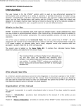
TMS-220 USB to I2C Host Adapter User's Manual Revision A Copyright © 2007 - Triangle Micro Solutions, Inc. All rights reserved. Page 2 of 42 Triangle Micro Solutions, Inc. 25 Oak Hollow Court Louisburg, North Carolina 27549 USA Email: On-line visit: By Phone: Document Revision: Date: Supports: sales@trianglemicr o.com [email protected] http://www.trianglemicro.com (919) 495-0622 A February 2007 TMS-220 Firmware Revision 1.0 Limited Warranty Triangle Micro Solutions, Inc. warrants this product for a period of one year from the original date of purchase. This warranty is extended to the original purchaser only. This warranty only covers defects in material or workmanship for the TMS-220 module only. The interface cables or other accessories are not covered. If the TMS-220 module fails to operate properly within this one year period, it will be repaired or replaced at the discretion of Triangle Micro Solutions, Inc. The consumer is responsible for shipping charges to return products for any reason. The consumer must contact Triangle Micro Solutions and inform us prior to returning any merchandise. This warranty is void if, in the opinion of Triangle Micro Solutions, Inc., the product has become nonfunctional for any of the following reasons: damaged by accident, misuse, or modified in anyway by unauthorized personnel. Statement of Non Compliance This device generates and uses radio frequency (RF) energy and could emit sufficient levels of RF energy to interfere with other devices. An increase in emissions is possible when this device is connected to external equipment. This device is intended to be used in a laboratory environment only. It has not been tested for compliance with the limits for a class A computing device pursuant to subpart J of part 15 of the FCC regulations. It is the user’s responsibility to take corrective action if interference occurs. USE THIS DEVICE AT YOUR OWN RISK! Please read this documentation before using the TMS-220. While the TMS-220 can be a useful tool, it must also be understood that the TMS-220 could render target devices non-functional. If you are using the TMS220 to write data to EEPROM memory devices, be sure to make a back up copy of any data that is critical for the operation of the device. Triangle Micro Solutions is not responsible for any malfunctions, damage, loss of business, or loss of data caused by the TMS-220 regardless of how the damage occurs. These devices are not designed for use in life support appliances, devices, systems or in any application where a malfunction may reasonably be expected to cause personal injury or loss of life. Trademarks Windows is a trademark of Microsoft ® Corporation I2C is a trademark of Philips Corporation Copyright © 2007, Triangle Micro Solutions, Inc. All Rights Reserved. Copyright © 2007 - Triangle Micro Solutions, Inc. All rights reserved. Page 3 of 42 Copyright © 2007 - Triangle Micro Solutions, Inc. All rights reserved. Page 4 of 42 Record of Revisions Revision A Date 28-Feb-07 Section All Change Initial release of document Copyright © 2007 - Triangle Micro Solutions, Inc. All rights reserved. Page 5 of 42 Copyright © 2007 - Triangle Micro Solutions, Inc. All rights reserved. Page 6 of 42 Table of Contents TABLE OF FIGURES ................................ ................................ ................................ ............................ 9 1 INTRODUCTION ................................ ................................ ................................ ......................... 11 1.1 1.2 1.3 1.4 1.5 2 HARDWARE ................................ ................................ ................................ ................................ . 14 2.1 2.2 2.3 2.4 3 DESCRIPTION ................................ ................................ ................................ ............................ 11 SUPPORTING DOCUMENTS ................................ ................................ ................................ ......... 11 FEATURES ................................ ................................ ................................ ................................ 11 SPECIFICATIONS ................................ ................................ ................................ ....................... 12 APPLICATIONS ................................ ................................ ................................ .......................... 13 INTERFACE MODULE ................................ ................................ ................................ ................. 14 TMS-220 INTERFACE CABLE ................................ ................................ ................................ .... 15 CUSTOM INTERFACE SOLUTION ................................ ................................ ................................ . 16 INTERFACE CABLE DATA ................................ ................................ ................................ .......... 17 USING THE TMS-220 ................................ ................................ ................................ .................. 18 3.1 INSTALLING THE TMS-220 INTERFACE MODULE ................................ ................................ ....... 18 3.2 INSTALLING THE USB PORT DRIVER ................................ ................................ ......................... 18 3.2.1 Identifying the Serial Port (COM Port) ................................ ................................ ........... 21 3.2.2 Changing the Serial Port (COM Port) ................................ ................................ ............. 21 3.3 CONNECTION TO I2C BUS ................................ ................................ ................................ .......... 21 3.4 SOFTWARE ................................ ................................ ................................ ............................... 22 3.5 FIRST TIME USAGE ................................ ................................ ................................ ................... 23 3.6 ASCII COMMAND PROTOCOL ................................ ................................ ................................ ... 23 3.6.1 Command Summary ................................ ................................ ................................ ........ 25 3.6.1.1 3.6.1.2 3.6.1.3 3.6.1.4 3.6.1.5 3.6.1.6 3.6.1.7 3.6.1.8 3.6.1.9 3.6.1.10 3.6.1.11 3.6.1.12 3.6.1.13 3.7 3.8 4 Command: /A – Address Configuration ................................ ................................ ....................... 26 Command: /B – Reboot the TMS-220................................ ................................ .......................... 27 Command: /C – Show the Current Configuration ................................ ................................ ......... 28 Command: /D – Discover Network Nodes ................................ ................................ ................... 29 Command: /F – Format Options................................ ................................ ................................ ... 30 Command: /G – General Call Support................................ ................................ .......................... 31 Command: /H - Help Command ................................ ................................ ................................ .. 32 Command /K: Set or Read the Master Clock Rate ................................ ................................ ........ 33 Command /M: Set or Read the Mode ................................ ................................ ........................... 34 Command /X: Radix Control ................................ ................................ ................................ ... 35 Command /R: Read I2C Slave Device ................................ ................................ ...................... 36 Command: /S Serial Number ................................ ................................ ................................ ... 37 Command /W: Write to I2C Slave Device ................................ ................................ ................ 38 I2C MASTER OPERATING MODE ................................ ................................ ................................ 39 I2C SLAVE OPERATING MODE ................................ ................................ ................................ ... 39 TROUBLESHOOTING ................................ ................................ ................................ ................ 41 4.1 4.2 NO PROMPT SEEN WHEN ENTER KEY PRESSED ................................ ................................ .......... 41 ERROR MESSAGES ................................ ................................ ................................ .................... 42 Copyright © 2007 - Triangle Micro Solutions, Inc. All rights reserved. Page 7 of 42 Copyright © 2007 - Triangle Micro Solutions, Inc. All rights reserved. Page 8 of 42 Table of Figures Figure Figure Figure Figure Figure Figure Figure Figure Figure Figure Figure 2-1: TMS-220 I2C Host Adapter (Interface Module) ................................ ................................ ..... 14 2-3: Cable for Custom Applications (option P/N TMS-CBL) ................................ ........................ 16 2-4: RJ-45 Connector on TMS-220 (Front View) ................................ ................................ .......... 17 3-1: Found New Hardwar e Dialog ................................ ................................ ................................ 18 3-2: Choose Installation Mode ................................ ................................ ................................ ...... 19 3-3: Windows ® Logo Test Warning ................................ ................................ .............................. 19 3-4: Software Installation Progress ................................ ................................ ............................... 20 3-5: Final Installation Dialog ................................ ................................ ................................ ........ 20 3-6: Typical I2C Bus Connecti on ................................ ................................ ................................ .. 22 3-7: TMS-220 Slave Response to Write Command ................................ ................................ ....... 39 3-8: TMS-220 Slave Response to Read Command ................................ ................................ ........ 40 Copyright © 2007 - Triangle Micro Solutions, Inc. All rights reserved. Page 9 of 42 Copyright © 2007 - Triangle Micro Solutions, Inc. All rights reserved. Page 10 of 42 1 Introduction 1.1 Description The TMS-220 is an I2C Bus Host Adapter with a USB interface to the host computer . The TMS-220 uses an ASCII protocol and is backward compatible with our TMS-200 and TMS-210 I2C Bus Host Adapters. The TMS-220 connects directly to the USB port of your computer using a standard USB-A Male / USB-B Male cable. The USB port provides power for the TMS-220 therefore no external power supply is required. The TMS-220 serves as an I2C bus master or slave that can be controlled by your computer . In order to make the connection to the I2C bus, an interface cable is provided. The interface cable is terminated with micro grabbers that can be attached directly to pin of an integrated circuit (DIP or SOIC). 1.2 Supporting Documents Reference documents: 1.3 I2C Bus Specification V2.1 (Philips Corporation) Visit http://www.semiconductors.philips.com/buses/i2c to obtain this document. Features Features of the TMS-220 include: Functions as an I2C master Functions as an I2C slave Supports 7-bit and 10-bit addressing modes User selectable I2C bus data rate up to 400 Kbps USB port powered, so external power adapters is not needed. Simple, easy to remember ASCII protocol. Includes USB drivers for the follow operating systems: Windows ® 98, 98SE, 2000, ME, XP, CE (4.2), and Linux (2.40 and greater). USB driver appears a COM port, so the TMS-220 can work with standard software such as Microsoft ® Hyper Terminal Easy to program using scripting or macro or high level languages. Data formatting control including Hex dump mode for reading EEPROM memories. Copyright © 2007 - Triangle Micro Solutions, Inc. All rights reserved. Page 11 of 42 1.4 Specifications The following specifications apply to the TMS-220 Host Adapter: Interface Module Voltage: Current Draw: I2C Bus Speed (Master Mode): USB Baud Rate: I2C Bus Connector: Mechanical Dimensions: Operating Temperature: +5V (supplied by the USB port) TBD 40K, 10K, 40K, 100K, 400K 57.6K RJ-45 3 in. x 1.625 in. x 0.750 in. 0°C (32°F) to TBD °C (70°F) Table 1-1: Specifications Copyright © 2007 - Triangle Micro Solutions, Inc. All rights reserved. Page 12 of 42 1.5 Applications There are many possible applications for the TMS-220. Here are just a few ideas. Product Development: 1. Experiment with new I2C devices to study their behavior. 2. Debugging new circuit board designs. 3. Program I2C serial EEPROM devices during the initial stage of firmware development. 4. Hardware / Software Integration Testing Manufacturing: 1. Production Test Equipment 2. Serial EEPROM initialization and test. The TMS-220 can be used to read or write any EEPROM that supports the I2C protocol. 3. Subassembly testing, especially if the system master is normally contained on a separate circuit board. Electronic Repair and Maintenance: 1. Equipment calibration. 2. Restore factory default data to EEPROM memories. 3. Security code reprogramming. Copyright © 2007 - Triangle Micro Solutions, Inc. All rights reserved. Page 13 of 42 2 Hardware 2.1 Interface Module The hardware consists of a small plastic enclosure, which contains a microcontroller. The microcontroller connects to your computer's serial port through USB port. Located on the bottom of the TMS-220 is the RJ-45 jack, which is used to connect the TMS-220 to the I2C bus. The interface cable plugs into the RJ-45 jack. Image 2.1 shows a TMS-220. Figure 2-1: TMS-220 I2C Host Adapter (Interface Module) Copyright © 2007 - Triangle Micro Solutions, Inc. All rights reserved. Page 14 of 42 2.2 TMS-220 Interface Cable The Interface Cable supplied with the TMS-220 is terminated on one end with a RJ45 plug, which is inserted into the TMS-220 interface module. The other end is terminated with pin receptacles, which can be inserted onto the test hooks supplied. The supplied test hooks are suitable for connecting the TMS-220 directly to target circuits. Copyright © 2007 - Triangle Micro Solutions, Inc. All rights reserved. Page 15 of 42 2.3 Custom Interface Solution If you would like to create your own custom interface solution, you may purchase a cable without terminations on the target side and connect it however you wish. For example, you may want to use a special connector or you may want to wire it directly to your equipment. Spare (non-terminated) cables may be obtained from Triangle Micro Solutions (option P/N TMS-CBL). The cable supplied is approximately 7 ft. (2.1 m) in length and is terminated only at one end with the RJ45 connector. Use the information listed in table 2.1 below to determine how to connect the cable to your hardware. Figure 2-2: Cable for Custom Applications (option P/N TMS-CBL) Copyright © 2007 - Triangle Micro Solutions, Inc. All rights reserved. Page 16 of 42 2.4 Interface Cable Data Information is provided here which may be useful should you decide to create a custom interface solution. Table 2-1 below identifies the function, wire color, and test hook color for both of the cables described in the previous sections. Figure 3.6 (below the table) shows the RJ-45 connector on the TMS-220 with pins 1 and 8 shown as a reference. Modular Connector Pin Number 1 2 3 4 5 6 7 8 Function Wire Color Test Hook Colors I2C Cable Not Used Not Used Ground SCL (clock) Not Used SDA (data) Not Used Not Used Orange Grey Black Green Red Yellow Brown Blue Not Used Not Used Black Green Not Used Yellow Not Used Not Used Table 2-1: Interface Cable Data Pin 1 Pin 8 Figure 2-3: RJ-45 Connector on TMS-220 (Front View) Copyright © 2007 - Triangle Micro Solutions, Inc. All rights reserved. Page 17 of 42 3 Using the TMS-220 3.1 Installing the TMS-220 Interface Module To install the TMS-220 Interface Module, connect a USB cable to the interface module and connect the TBD side of the cable to any available USB port on your computer . The first time that you connect the TMS-220, your computer should indicate “new hardware found”. Your computer will ask for the location of a device driver. 3.2 Installing the USB Port Driver Insert the CD-ROM supplied with the TMS-220 into your CD-ROM drive. Upon connecting the TMS-220 to your computer’s USB port for the first time, you will see the following dialog window. Select “No, not this time” and select “Next”. Figure 3-1: Found New Hardware Dialog In the next dialog window, you will be asked how to install the driver software. Choose “Install the software automatically (recommended)” and click “Next” to continue. Copyright © 2007 - Triangle Micro Solutions, Inc. All rights reserved. Page 18 of 42 Figure 3-2: Choose Installation Mode The next dialog window will indicate that the “USB High Speed Serial Converter” has not passed Windows ® Logo testing. Select “Continue Anyway”. Figure 3-3: Windows ® Logo Test Warning Copyright © 2007 - Triangle Micro Solutions, Inc. All rights reserved. Page 19 of 42 Figure 3-4: Software Installation Progress Figure 3-5: Final Installation Dialog The USB High Speed Serial Converter software that you have installed appears as a standard “Com Port” to your software. Therefore there will be a port number assigned to it once it has been installed (for example COM4). This is a virtual com port but to your software it appears as a real com port. This allows you to use common software that was originally designed to work with RS-232 style COM ports. Copyright © 2007 - Triangle Micro Solutions, Inc. All rights reserved. Page 20 of 42 3.2.1 Identifying the Serial Port (COM Port) When the USB driver is installed, a specific serial port assignment will be made. You will need to know the serial port being used by the TMS-220 so that your application software (i.e. Microsoft ® Hyper Terminal) can be configured to communicate with the TMS-220. To determine the serial port selection under Windows ® XP, follow these steps: 1. Click the “Start” button in the lower left corner of (Windows ® Task Bar). 2. Select “Settings” 3. Select “Control Panel”. 4. From the Control Panel select “System”. 5. In the “System Properties” dialog box, select the “Hardware” tab 6. Select “Device Manager”; within the “Device Manager” dialog box, there should be a tree diagram of all devices installed on the system. 7. Find the branch labeled “Ports (COM and LPT)”. Expand this branch to find the port labeled “USB Serial Port”. This is the port used the TMS-220. The COM port in use will be listed. 3.2.2 Changing the Serial Port (COM Port) The port chosen by the installation software may not be the port that you want to use because it may not be supported by your software. If you want to change the 3.3 Connection to I2C Bus Connecting the TMS-220 to the I2C bus can be accomplished in a number of ways. The most direct method is shown below in image 3.1, which shows a TMS-200 connected to a I2C EEPROM. Consult the chip documentation for I2C bus connections on other chips and packages. Note that Image 3.1 shows a TMS-200 connection. A TMS-210 connection must have the RED test clip attached to a suitable voltage source (i.e.: the Vcc pin of the target I2C device). Copyright © 2007 - Triangle Micro Solutions, Inc. All rights reserved. Page 21 of 42 Clock (SCL) Data (SDA) Target I2C Device Vss (GND) Figure 3-6: Typical I2C Bus Connection WARNING: Only connect the TMS220 to target circuits when power is shut off. Take care not to inadvertently allow probes to come in contact with adjacent pins once power is applied. 3.4 Software There is no application software supplied with the TMS-220. To use the TMS-220 you will need either Terminal Emulation Software or custom software that create you self. You may have terminal emulation software installed on your computer (such as Microsoft ® Hyper Terminal). If you do not have terminal emulation software and you are using the Microsoft ® OS, you can download the TeraTerm program from the URL listed here. http://hp.vector.co.jp/authors/VA002416/teraterm.html The TeraTerm program has a built-in macro language that is easy to learn and is ideal for creating simple utilities for use with the TMS-220. Copyright © 2007 - Triangle Micro Solutions, Inc. All rights reserved. Page 22 of 42 3.5 First Time Usage Once the TMS-220 has been installed and you have it connected to the I2C bus, start your terminal emulation software. Pressing the Enter key (CR) should cause the prompt (TMS-220>) to be displayed in your terminal window. If you do not see the prompt, consult the Troubleshooting section at the end of this manual. Once you have the prompt, just enter commands as described in section 3.5. 3.6 ASCII Command Protocol The TMS-220 uses a pure ASCII command protocol. All commands begin with the forward slash "/", followed by a letter of the alphabet (case insensitive). Then additional bytes may follow as defined by the specific command. Command arguments may be provided in hexadecimal (0x7F) or decimal (127) notation. Data output will default to hexadecimal format, but the radix (/X) command permits the user to change the format to decimal. All of the symbols that make up output messages from the TMS-220 are shown in Table 3-1 below. Symbol S P A N [ ] 00 - FF Meaning I2C Bus Start Condition I2C Bus Stop Condition I2C ACK I2C NAK Square brackets surround the slave address Data shown in HEX (no leading 0x) Table 3-1: Output data symbols and their meanings The default output is structured in a similar manner as an actual I2C bus transmission with the START condition represented by the 'S'. Next is the slave address of the I2C device that we are sending the message to, surrounded by square brackets. After that, the ACK, is shown (represented by the 'A'). Then the data follows along with ACK’s shown as 'A's and NAK’s shown as the 'N'. Finally, 'P' indicates the stop condition. This format can be modified using the Display Mode Configuration Command. Enter commands at the prompt ("TMS-220>" or "TMS-220<"). Note that the prompt indicates the current mode of the TMS-220 with either the greater than symbol (>) when in slave mode and the less than symbol (<) when in the slave mode. The TMS-220 supports the backspace key to delete characters from the command line. To execute the command, press the <Enter> key. In all of the examples presented in this manual, text entered by the user is shown in BLUE. All Copyright © 2007 - Triangle Micro Solutions, Inc. All rights reserved. Page 23 of 42 commands are terminated with the "Enter" or "Carriage Return" shown like this <CR>. Address and data may be entered as hex or decimal. If entered in hex, use the "0x" to denote that the data is hex. Example Command: TMS-220> /R 0xA0 0x05 <CR> Example Response: I2C Read: S [A1] A 55 A 55 A 55 A 55 A 55 N P NOTE: This space not required TMS-220> Each command description shows the command syntax. The command syntax field uses angle brackets like <arg> to indicate that the argument is required. Optional command arguments are shown enclosed in square brackets like this [arg]. Copyright © 2007 - Triangle Micro Solutions, Inc. All rights reserved. Page 24 of 42 3.6.1 Command Summary Table of commands recognized by the TMS-220: Command Arguments /A [address] /B None /C None /D None /F [mode] /G /H /K /M /R /S /W [0|1] None [0|1|2|3|4] [0|1|2] <address><num> None <address><data> /X [0|1] Purpose Read or write the slave address for TMS-220 to use when in slave mode. Reset or reboot the TMS-220 Display TMS-220 configuration (current state of all module parameters) Discovery command. This command polls to bus to determine what I2C devices are attached Read or write the format control byte. The format control is applied to displayed data in the master mode. Read or write the general call support control Display help Read or write the master clock rate Read or write the mode Master mode read command Display the serial number Master mode write command Read of write the radix (supports decimal or hexadecimal) Table 3-2: Summary of Commands Copyright © 2007 - Triangle Micro Solutions, Inc. All rights reserved. Page 25 of 42 3.6.1.1 Command: /A – Address Configuration Use this command to view the current slave address setting or change the slave address setting of the TMS-220. This command sets slave address values for both 7-bit and 10-bit modes. When there are no arguments supplied, the TMS-220 will return the current setting. When one argument is supplied, the TMS-220 will write a 7-bit address. When two arguments are supplied, the TMS-220 will write a 10bit address. Command Syntax: /A [address ] Arguments: address – (optional): When supplied, the address argument is configured as the new slave address. The address argument may be supplied as an 8-bit argument in the range of 0 – 255 decimal (0x00 – 0xFF Hex), or as a 16-bit value (for 10-bit addressing modes). Example 1: Read the current slave address setting. TMS-220> /A <CR> Slave address (7-bit): 50 Slave address (10-bit): FF50 TMS-220> Example 2: Write a 7-bit address. TMS-220> /A A0 <CR> Slave address (7-bit): 50 Slave address (10-bit): FF50 Setting 7-bit slave address to: A0 TMS-220> Example 3: Write 10-bit address. TMS-220> /A F0 10 <CR> Slave address (7-bit): 00 Slave address (10-bit): FF00 Setting 10-bit slave address to: F010 TMS-220> Copyright © 2007 - Triangle Micro Solutions, Inc. All rights reserved. Page 26 of 42 3.6.1.2 Command: /B – Reboot the TMS-220 Use this command to reboot the TMS-220. Command Syntax: /b Arguments: None Example: Reboot the TMS-220 TMS-220> /B <CR> Rebooting... TMS-220 I2C Host Adapter V0.0.0 Built Nov 06 2006 at 22:42:25. Copyright(c)2005 Triangle Micro Solutions, All rights reserved. www.TriangleMicro.com TMS-220> Copyright © 2007 - Triangle Micro Solutions, Inc. All rights reserved. Page 27 of 42 3.6.1.3 Command: /C – Show the Current Configuration This command is used to show the current configuration of the TMS-220. Once issued, the TMS-220 displays current settings which as stored in non-volitile memory. Command Syntax: /C Arguments: None Example: Display the current TMS-220 configuration. TMS-220> /C <CR> TMS-220 Configuration ============================= Serial number .......... Operational Mode ....... Show NAK ............... Show ACK ............... Show START ............. Show STOP .............. Memory dump mode ....... Master clock rate ...... Radix .................. Slave Address (7-bit)... Slave Address (10-bit).. General call support ... 12345 I2C Master ON ON ON ON OFF 100K HEX 50 FF50 DISABLED TMS-220> Copyright © 2007 - Triangle Micro Solutions, Inc. All rights reserved. Page 28 of 42 3.6.1.4 Command: /D – Discover Network Nodes Use the discover command to identify all slave devices attached to an I2C bus. The command will poll 0x00 – 0xFC will be polled to determine which devices are active. Command Syntax: /D Arguments: None Example: Poll addresses and show ACK / NAK result. Note, to save space only the first two and last two are shown in this example. TMS-220> /D <CR> Polling the network... Polled 00 got NAK. Polled 02 got NAK. …… Polled FA got NAK. Polled FC got NAK. Done. TMS-220> Copyright © 2007 - Triangle Micro Solutions, Inc. All rights reserved. Page 29 of 42 3.6.1.5 Command: /F – Format Options The data output format may be altered using this command. When setting the display mode, one argument is supplied. The display configuration data is bitwise encoded as described in table 3.3 below. Command Syntax: /F [mode] Arguments: mode - (optional): When not supplied, the current value is displayed. To write a new display mode, send the command with the mode argument. Encode the bits as shown in the table. The default value at power-up is 0x0F. Example: Configure the TMS-220 to output data in "memory dump" format. In this format, data is displayed in columns with the left most column containing the address. TMS-220> /F 0x10 <CR> Memory dump mode enabled. Format options = 0x10 TMS-220> BIT 0 1 2 3 4 5 6 7 Control Byte - FORMAT_OPTIONS Show NAK responses (Default = 1 - Enabled) Show ACK responses (Default = 1 - Enabled) Show START condition (Default = 1 - Enabled) Show STOP condition (Default = 1 - Enabled) Enable memory dump format for output. (Bits 0 - 3 must be 0 in this mode) (Defaul t = 0 - Disabled) Not Used - Leave as 0 Not Used - Leave as 0 Not Used - Leave as 0 Table 3.3: Display Mode Output Copyright © 2007 - Triangle Micro Solutions, Inc. All rights reserved. Page 30 of 42 3.6.1.6 Command: /G – General Call Support This command is used to enable the general call support feature to be enabled or disabled. Command Syntax: /G [mode] Argument: mode – (optional): When supplied, the mode condition is updated and saved. When mode is supplied as 0, the general call option is disabled. When mode is supplied as 1, the general call support is disabled. Example 1: This example shows the current general call support configuration TMS-220> /G <CR> General call support: DISABLED TMS-220> Example 2: This example enables the General Call support feature. TMS-220> /G 1 <CR> General call support: DISABLED Enabling General Call Support General call mode successfully updated TMS-220> Copyright © 2007 - Triangle Micro Solutions, Inc. All rights reserved. Page 31 of 42 3.6.1.7 Command: /H - Help Command The help command provides a list of all commands available, the syntax for each command , and the arguments for each command. Arguments shown in [ ] brackets are optional. Arguments shown in < > brackets are required. In addition, the current firmware version is also shown. Command Syntax: /H or Arguments: None Example: Display help screen. /h or /? TMS-220> /H <CR> TMS-220 I2C Host Adapter V0.0.0 Built Nov 06 2006 at 22:42:25. Copyright(c)2005 Triangle Micro Solutions, All rights reserved. www.TriangleMicro.com Help command Usage: /A [address] /B /C /D - /F [mode] - /G [0|1] - /H /K [0|1|2|3|4] - /M [0|1|2] - /R <addr> <num> - /S /W <addr> <d1..dn> /X [0|1] - Write slave address (0x50 is default) (slave mode only) Reset (reboot) the TMS-220 Show current TMS-220 configuration Poll all I2C addresses to discover what devices are available Format output data (0x0F is default) Argument [mode] is bit mapped as follows: Bit 0 - Show NAK Bit 1 - Show ACK Bit 2 - Show START Bit 3 - Show STOP Bit 4 - Memory dump mode Bits 5 - 7 are not used General call support (slave mode only) 0 - Disabled (default) 1 - Enabled Show this HELP screen (also /?) Set the master mode clock 0 - 40K bits 1 - 80K bits 2 - 100K bits 3 - 200K bits 4 - 400K bits Show or set the mode 0 - I2C Master Mode (Default) 1 - I2C 7-bit slave 2 - I2C 10-bit slave Read from slave I2C device addr - I2C Device Address num - Number of bytes to read from addr Display the TMS-220 serial number Write data to slave I2C device Set radix 0=Hex (default) 1=Decimal Square brackets [ ] indicate optional arguments. Angle brackets < > indicate required arguments. TMS-220> Copyright © 2007 - Triangle Micro Solutions, Inc. All rights reserved. Page 32 of 42 3.6.1.8 Command /K: Set or Read the Master Clock Rate Use this command to set the master mode clock rate to one of the following values: 40Kbps, 80Kbps, 100Kbps, 200Kbps or 400Kbps. The command may also be used to read the current clock rate. The clock rate being set or read is relevant to the master mode of operation only. Command Syntax: /K [rate] Arguments: rate – (optional): When supplied, the bit rate for the I2C bus clock is updated to the value represented by rate (0-4). Example 1: Read the current I2C bus clock rate. TMS-220> /K <CR> Current I2C master clock rate is: 100K Example 2: Set master clock rate to 400K. TMS-220> /K 4 <CR> Current I2C master clock rate is: 100K Requested I2C master clock rate is: 400K I2C master clock successfully updated. Copyright © 2007 - Triangle Micro Solutions, Inc. All rights reserved. Page 33 of 42 3.6.1.9 Command /M: Set or Read the Mode The command is used to set the mode of the TMS-220. The TMS-200 can be operated in one of three modes: bus master, slave (7-bit addressing) or slave (10bit addressing.) The mode can be determined by observing the prompt. Command Syntax: /M [mode] Arguments: mode – (optional): When supplied, this specifies the desired operating mode as follows: 0 = Master Mode (default) 1 = Slave Mode (7-bit addressing) 2 = Slave Mode (10-bit addressing) Example 1: Show the current mode. TMS-220> /M <CR> Current mode is: I2C Master TMS-220> Example 2: Set the mode to slave mode with 7-bit addressing . TMS-220> /M 1 <CR> Current mode is: I2C Master New mode selection: I2C 7-Bit Slave Mode successfully updated. TMS-220< Example 3: Set the mode to slave mode with 10-bit addressing . TMS-220> /M 2 <CR> Current mode is: I2C Master New mode selection: I2C 10-Bit Slave Mode successfully updated. TMS-220<< Example 4: Set the mode to master mode. TMS-220<< /M 0 Current mode is: I2C 10-Bit Slave New mode selection: I2C Master Mode successfully updated. TMS-220> Copyright © 2007 - Triangle Micro Solutions, Inc. All rights reserved. Page 34 of 42 3.6.1.10 Command /X: Radix Control Use this command to view and modify the current radix for output data. The default value is 1, which indicates the radix is base 16 (HEX). Setting the value to 0 makes the radix base 10 (decimal). This affects the data fields in the output from both the read or writes commands. Command Syntax: /X [radix] Arguments: radix - (optional): When not supplied, the command responds with the current radix setting. When supplied, it should only be 0 or 1. 1 = Format data in hex (default) 0 = Format data in decimal. Example 1: Set the radix to base 10, decimal. TMS-220> /X 0 <CR> Radix is DEC Example 2: Set the radix to base 16, hexadecimal. TMS-220> /X 1 <CR> Radix is: HEX Setting radix to: DEC Configurati on successfully updated TMS-220> Copyright © 2007 - Triangle Micro Solutions, Inc. All rights reserved. Page 35 of 42 3.6.1.11 Command /R: Read I2C Slave Device This command initiates a write operation to a device on the I2C bus. There are two required arguments. The first argument is the slave device address. The second is the number of bytes that you want to read. The format of the output from this command may be altered by using the /F (format control) command. Command Syntax: /R <address> <num_bytes> Arguments: address (required) - The address of the slave device that the read command is intended for. num_bytes (required) - The number of bytes to be read from the slave device. Example 1: Read 5 bytes from the current address of a 24C04 EEPROM. TMS-220> /R 0xA0 0x05 <CR> I2C Read: S [A1] A FF A FF A FF A FF A FF N P TMS-220> Copyright © 2007 - Triangle Micro Solutions, Inc. All rights reserved. Page 36 of 42 3.6.1.12 Command: /S Serial Number Display the serial number of the TMS-220. Command Syntax: /S Arguments: None Example: Read the TMS-220 serial number. TMS-220> /S <CR> TMS-220 Serial Number: 1234 TMS-220> Copyright © 2007 - Triangle Micro Solutions, Inc. All rights reserved. Page 37 of 42 3.6.1.13 Command /W: Write to I2C Slave Device This command performs a write operation to an I2C device on the bus. This command can be supplied with a variable number of data arguments. An optional repeat start condition is allowed with this command. The use of the repeat stop is shown in the second example. Command Syntax: /W <address> <data> … <data> [S] Arguments: address (required): The address of the device that you are writing to. data (required): The data to be written. At least one data byte is required. The maximum number of data bytes is limited by the size of the command line buffer and depends on how data is entered. For example, using ‘5F’ instead of ‘0x5F’ will permit more data to be entered into the buffer. S [optional]: This argument enables the repeat start condition. Example 1: Write the address byte of a 24C04 EEPROM to 0x00. TMS-220> /W 0xA0 0x00 <CR> I2C Write: S [A0] A 00 A P TMS-220> Example 2: Perform a random read from a 24C256 serial EEPROM. This example shows how to use the repeat start feature. This operation must be performed in two steps. First, setup the address registers using the /W command terminated with a repeat start condition. Next, read data from the EEPROM using the /R command. TMS-220> /W 0xA0 0x00 0x00 S <CR> I2C Write: S [A0] A 00 A 00 A S TMS-220> /R 0xA0 0x05 <CR> I2C Read: S [A1] A 00 A 00 A 00 A 00 A 00 N P TMS-220> Copyright © 2007 - Triangle Micro Solutions, Inc. All rights reserved. Page 38 of 42 3.7 I2C Master Operating Mode When the TMS-220 is in I2C Master Mode, the following prompt is displayed: TMS-220> Enter commands at the prompt. The <BACKSPACE> key can be used to correct mistakes. Press the <ENTER> (or <CR>) key to execute a command. In master mode, I2C slave devices can be read using the read command as shown below: /R <address> <num_bytes> See the document ation in the previous section for examples . In order to use the read command, the slave address must be known. The data sheet for the device that you wish to read data from should be consulted to determine the address. Some devices may respond to multiple addresses, depending on pin programming or register programming. 3.8 I2C Slave Operating Mode When the TMS-220 is in I2C Slave Mode, the following prompt is displayed: TMS-220< When an I2C master addresses the TMS-220 operating in slave mode for the purpose of writing data to it, the TMS-220 will display an exclamation mark to indicate that it is receiving data from a bus master. The TMS-220 will then display its address followed by all of the data received from the slave. The following example illustrated the process: Master Sends: Address: Data Byte 1: Data Byte 2: Data Byte 3: Data Byte 4: TMS-220 Slave (address = 0x50) Output: 0x50 0xAA 0x55 0xAA 0x55 TMS-220< ! 50 AA 55 AA 55 Figure 3-7: TMS-220 Slave Response to Write Command Copyright © 2007 - Triangle Micro Solutions, Inc. All rights reserved. Page 39 of 42 When an I2C master addresses the TMS-220 operating in slave mode for the purpose of reading data from it, the TMS-220 will display a question mark prompt, and wait for data to be supplied. The following example illustrated the process: Read 5 bytes from the slave device who’s TMS-220 Slave (at address = 0x50) address is 50 hex. Master Sends: Address: Data Byte 1: 0x50 0x05 Output: TMS-220< ? AA Enter ? 55 Enter ? AA Enter ? 55 Enter ? AA Enter data at ‘?’ prompt data at ‘?’ prompt data at ‘?’ prompt data at ‘?’ prompt data at ‘?’ prompt Figure 3-8: TMS-220 Slave Response to Read Command Copyright © 2007 - Triangle Micro Solutions, Inc. All rights reserved. Page 40 of 42 4 Troubleshooting This section is provided to assist users of the TMS-220 to troublesh oot and fix problems that might arise. Should you encounter a problem that can not be solved using the information that is contained here, contact [email protected] for assistance. 4.1 No Prompt Seen when Enter Key Pressed If you do not see the TMS-220 prompt, follow the check list below. 1. Verify that you have the correct communications port selected for the software that you are using, and that the TMS-220 is connected to the port that you have selected. 2. If you are using terminal emulation software (such as TeraTerm), verify that the proper communications port has been selected in the applications configuration dialog. 3. Verify that your software is configured for the correct serial port, and that the communications parameters are set as shown in table 4.1 below. Parameter Baud Rate Data Bits Parity Stop Bits Flow Control TMS-220 57,600 8 None 1 None Table 4.1: Serial Port Parameters 4. Verify that the target circuit is powered. 5. After checking all of these things, if you still are having difficulty, try disconnecting the TMS-220 from the host, wait 10 seconds and then reconnect it to the host. The boot up message should appear on the terminal window. Copyright © 2007 - Triangle Micro Solutions, Inc. All rights reserved. Page 41 of 42 4.2 Error Messages The following table summarizes the various error messages that may be displayed by the TMS-220 along with the probable cause and the commands that are capable of generating them. No. Error Message 1 ERROR: Failed to save mode 2 ERROR: No change in value 3 ERROR: Syntax error 4 ERROR: Too many arguments 5 ERROR: Failed to save configuration change 6 ERROR: Invalid rate (use: 0=40K, 1=80K, 2=100K, 3=200K, 4=400K) 7 ERROR: Invalid mode requested 8 ERROR: Invalid radix (0=HEX, 1=DEC) 9 Syntax error - Invalid slave address. 10 Command not available in slave mode. 11 ERROR: Upper byte of 10-bit slave address must be B'1111.0XX[R/W]' Cause Commands Configuration data not saved to internal memory. Supplied argument is the same as current configuration. No change made. The command was not formatted properly or the command is not a valid or supported command. There were more arguments than expected supplied with the command. Consult the section of this document for the command to see the required and optional arguments. Configuration data not saved to internal memory. Rate requested is not available. Choose another rate from the selection. Requested mode is not available. Choose another mode. Radix code is not available. Choose a radix code from the list supplied (0 or 1). The slave address is not valid. Choose a valid address. The read command is not supported when the TMS-220 is configured as a slave device. The slave 10-bit slave address was not correct. Try another address that follows the supplied pattern. /F End of Document Copyright © 2007 - Triangle Micro Solutions, Inc. All rights reserved. Page 42 of 42 /F, /G, /K, /M, /X /F, /G, /K /X, /A /F, /G, /K, /X, /R, /A /G, /K, /M, /X /K /M /X /R, /A /R, /W /A