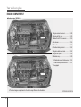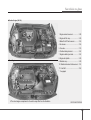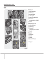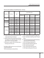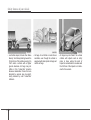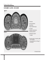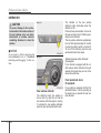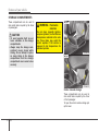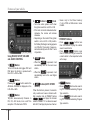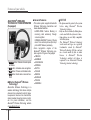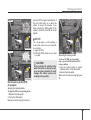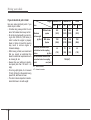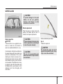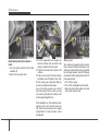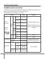
1
Introduction
How to use this manual / 1-2
Fuel requirements / 1-2
Vehicle break-in process / 1-6
Indicator symbols on the instrument cluster / 1-7
1
Introduction
FUEL REQUIREMENTS
HOW TO USE THIS MANUAL
We want to help you get the greatest
possible driving pleasure from your vehicle. Your Owner’s Manual can assist you
in many ways. We strongly recommend
that you read the entire manual. In order
to minimize the chance of death or injury,
you must read the WARNING and CAUTION sections in the manual.
Illustrations complement the words in this
manual to best explain how to enjoy your
vehicle. By reading your manual, you
learn about features, important safety
information, and driving tips under various road conditions.
The general layout of the manual is provided in the Table of Contents. Use the
index when looking for a specific area or
subject; it has an alphabetical listing of all
information in your manual.
Sections: This manual has eight sections
plus an index. Each section begins with a
brief list of contents so you can tell at a
glance if that section has the information
you want.
1 2
You will find various WARNINGs,
CAUTIONs, and NOTICEs in this manual. These WARNINGs were prepared to
enhance your personal safety.You should
carefully read and follow ALL procedures
and recommendations provided in these
WARNINGs, CAUTIONs and NOTICEs.
WARNING
A WARNING indicates a situation in
which harm, serious bodily injury or
death could result if the warning is
ignored.
CAUTION
A CAUTION indicates a situation in
which damage to your vehicle could
result if the caution is ignored.
✽ NOTICE
A NOTICE indicates interesting or helpful information is being provided.
Gasoline engine
Unleaded
For Europe
For the optimal vehicle performance, we
recommend you to use unleaded gasoline which complies with EN 228 and has
an octane rating of RON (Research
Octane Number) 95 / AKI (Anti Knock
Index) 91 or higher.
You may use unleaded gasoline with an
octane rating of RON 91~94 / AKI 87~90
but it may result in slight performance
reduction of the vehicle.
Except Europe
Your new Kia vehicle is designed to use
only unleaded fuel having an Octane
Rating of RON (Research Octane
Number) 91 / AKI (Anti-Knock Index) 87
or higher.
Your new vehicle is designed to obtain
maximum performance with UNLEADED
FUEL, as well as minimize exhaust emissions and spark plug fouling.
Introduction
CAUTION
NEVER USE LEADED FUEL. The
use of leaded fuel is detrimental to
the catalytic converter and will
damage the engine control system’s oxygen sensor and affect
emission control.
Never add any fuel system cleaning
agents to the fuel tank other than
what has been specified. (We recommend that you consult an authorized Kia dealer.)
WARNING
• Do not "top off" after the nozzle
automatically shuts off when
refueling.
• Always check that the fuel cap is
installed securely to prevent fuel
spillage in the event of an accident.
Leaded (if equipped)
For some countries, your vehicle is
designed to use leaded gasoline. When
you are going to use leaded gasoline, we
recommend that you ask an authorized
Kia dealer.
Octane Rating of leaded gasoline is
same with unleaded one.
Gasoline containing alcohol and
methanol
Gasohol, a mixture of gasoline and
ethanol (also known as grain alcohol), and
gasoline or gasohol containing methanol
(also known as wood alcohol) are being
marketed along with or instead of leaded
or unleaded gasoline.
Do not use gasohol containing more than
10% ethanol, and do not use gasoline or
gasohol containing any methanol. Either
of these fuels may cause drivability problems and damage to the fuel system.
Discontinue using gasohol of any kind if
drivability problems occur.
Vehicle damage or drivability problems
may not be covered by the manufacturer’s
warranty if they result from the use of:
1. Gasohol containing more than 10%
ethanol.
2. Gasoline or gasohol containing
methanol.
3. Leaded fuel or leaded gasohol.
CAUTION
Never use gasohol which contains
methanol. Discontinue use of any
gasohol product which impairs drivability.
1 3
Introduction
Use of MTBE
Kia recommends avoiding fuels containing MTBE (Methyl Tertiary Butyl Ether)
over 15.0% vol. (Oxygen Content 2.7%
weight) in your vehicle.
Fuel containing MTBE over 15.0% vol.
(Oxygen Content 2.7% weight) may
reduce vehicle performance and produce
vapor lock or hard starting.
CAUTION
Your New Vehicle Limited Warranty
may not cover damage to the fuel
system and any performance problems that are caused by the use of
fuels containing methanol or fuels
containing MTBE (Methyl Tertiary
Butyl Ether) over 15.0% vol. (Oxygen
Content 2.7% weight.)
Do not use methanol
Fuels containing methanol (wood alcohol) should not be used in your vehicle.
This type of fuel can reduce vehicle performance and damage components of
the fuel system.
Fuel Additives
Kia recommends that you use good quality gasolines meet Europe Fuel standards (EN228) or equivalents.
For customers who do not use good
quality gasolines including fuel additives
regularly, and have problems starting or
the engine does not run smoothly, one
bottle of additives added to the fuel tank
at every 15,000km (For Europe)/
5,000km (Except Europe). Additives are
available from your authorized Kia dealer
along with information on how to use
them. Do not mix other additives.
Operation in foreign countries
If you are going to drive your vehicle in
another country, be sure to:
• Observe all regulations regarding registration and insurance.
• Determine that acceptable fuel is available.
1 4
Diesel engine
Diesel fuel
Diesel engine must be operated only on
commercially available diesel fuel that
complies with EN 590 or comparable
standard. (EN stands for "European
Norm"). Do not use marine diesel fuel,
heating oils, or non-approved fuel additives, as this will increase wear and
cause damage to the engine and fuel
system. The use of non-approved fuels
and / or fuel additives will result in a limitation of your warranty rights.
Diesel fuel of above cetane 51 is used in
your vehicle. If two types of diesel fuel
are available, use summer or winter fuel
properly according to the following temperature conditions.
• Above -5°C (23°F) ... Summer type
diesel fuel.
• Below -5°C (23°F) ... Winter type diesel
fuel.
Watch the fuel level in the tank very carefully : If the engine stops through fuel failure, the circuits must be completely
purged to permit restarting.
Introduction
CAUTION
Do not let any gasoline or water
enter the tank. This would make it
necessary to drain it out and to
bleed the lines to avoid jamming the
injection pump and damaging the
engine.
CAUTION - Diesel Fuel
(if equipped with DPF)
It is recommended to use the regulated automotive diesel fuel for
diesel vehicle equipped with the
DPF system.
If you use diesel fuel including high
sulfur (more than 50 ppm sulfur)
and unspecified additives, it can
cause the DPF system to be damaged and white smoke can be emitted.
Biodiesel
Commercially supplied Diesel blends of
no more than 7% biodiesel, commonly
known as "B7 Diesel" may be used in
your vehicle if Biodiesel meets EN 14214
or equivalent specifications. (EN stands
for "European Norm"). The use of biofuels exceeding 7% made from rapeseed
methyl ester (RME), fatty acid methyl
ester (FAME), vegetable oil methyl ester
(VME) etc. or mixing diesel exceeding
7% with biodiesel will cause increased
wear or damage to the engine and fuel
system. Repair or replacement of worn or
damaged components due to the use of
non approved fuels will not be covered by
the manufactures warranty.
Biodiesel (for New Zealand)
Commercially supplied Diesel blends of
no more than 7% biodiesel, commonly
known as "B7 Diesel" may be used in
your vehicle if Biodiesel meets EN 14214
or equivalent specifications. (EN stands
for "European Norm"). The use of biofuels exceeding 7%, made from rapeseed
methyl ester (RME), vegetable oil methyl
ester (VME) etc. or mixing diesel exceeding 7% with biodiesel will cause
increased wear or damage to the engine
and fuel system. Repair or replacement
of worn or damaged components due to
the use of non approved fuels will not be
covered by the manufactures warranty.
CAUTION
CAUTION
• Never use any fuel, whether
diesel, B7 biodiesel or otherwise,
that fails to meet the latest petroleum industry specification.
• Never use any fuel additives or
treatments that are not recommended or approved by the vehicle manufacturer.
• Never use any fuel, whether
diesel or B7 biodiesel or otherwise that fails to meet the latest
petroleum industry specification.
• Never use any fuel additives or
treatments that are not recommended or approved by the vehicle manufacturer.
1 5
Introduction
VEHICLE BREAK-IN PROCESS
No special break-in period is needed. By
following a few simple precautions for the
first 1,000 km (600 miles) you may add to
the performance, economy and life of
your vehicle.
• Do not race the engine.
• While driving, keep your engine speed
(rpm, or revolutions per minute)
between 2,000 rpm and 4,000 rpm.
• Do not maintain a single speed for long
periods of time, either fast or slow.
Varying engine speed is needed to
properly break-in the engine.
• Avoid hard stops, except in emergencies, to allow the brakes to seat properly.
• Don't let the engine idle longer than 3
minutes at one time.
• Don't tow a trailer during the first 2,000
km (1,200 miles) of operation.
1 6
Introduction
INDICATOR SYMBOLS ON THE INSTRUMENT CLUSTER
Electric power steering
(EPS) system warning light*
Air bag warning light*
Tailgate open ajar warning light
ABS warning light*
Door ajar warning light
Auto stop for ISG system
indicator*
Seat belt warning light
Immobilizer indicator
Glow indicator (Diesel only)
Turn signal indicator
Shift pattern indicator*
Fuel filter warning light (Diesel only)
High beam indicator
Manual transaxle shift indicator*
Low tire pressure telltale* /
TPMS malfunction indicator*
Low beam indicator
Low fuel level warning light
Tail light indicator
Malfunction indicator light
Cruise SET indicator*
Front fog light indicator*
ESP indicator*
Speed limit indicator*
Rear fog light indicator*
ESP OFF indicator*
Engine oil pressure warning light
Parking brake & Brake
fluid warning light
Charging system warning light
EPS
Cruise control indicator*
CRUISE
ECO ECO indicator*
EPB Electric parking brake (EPB)
* : if equipped
AUTO
HOLD
AUTO HOLD indicator*
❈ For more detailed explanations, refer
to “Instrument cluster” in section 4.
120
Overspeed warning light*
malfunction indicator*
km/h
1 7
kia, the company
Thank you for becoming the owner of a new Kia vehicle.
As a global car manufacturer focused on building high-quality, value for
money prices, Kia Motors is dedicated to providing you with a customer
service experience that exceeds your expectations.
At all of our Kia dealerships you will be treated with warmth, hospitality
and professionalism by people who care based on our “Family-like Care”
promise.
All information contained in this Owner’s Manual is accurate at the
time of publication. However, Kia reserves the right to make changes
at any time so that our policy of continual product improvement can be
carried out.
This manual applies to all models of this vehicle and includes descriptions and explanations of optional as well as standard equipment. As a
result, you may encounter material in this manual that is not applicable
to your specific Kia vehicle.
Enjoy your vehicle and Kia’s “Family-like Care” experience!
Foreword
Thank you for choosing a Kia vehicle.
This manual will familiarize you with operational, maintenance and safety information about your new vehicle. It is
supplemented by a Warranty and Maintenance book that provides important information on all warranties regarding
your vehicle. Kia urges you to read these publications carefully and follow the recommendations to help assure
enjoyable and safe operation of your new vehicle.
Kia offers a great variety of options, components and features for its various models. Therefore, some of the equipment described in this manual, along with the various illustrations, may not be applicable to your particular vehicle.
The information and specifications provided in this manual were accurate at the time of printing. Kia reserves the
right to discontinue or change specifications or design at any time without notice and without incurring any obligation. If you have questions, always check with your authorized Kia dealer.
Kia assures you of our continuing interest in your motoring pleasure and satisfaction in your Kia vehicle.
© 2012 Kia MOTORS Corp.
All rights reserved. Reproduction by any means, electronic or mechanical, including photocopying, recording, or by
any information storage and retrieval system or translation in whole or part is not permitted without written authorization from Kia MOTORS Corporation.
Printed in Korea
i
table of contents
Introduction
1
Your vehicle at a glance
2
Safety features of your vehicle
3
Features of your vehicle
4
Driving your vehicle
5
What to do in an emergency
6
Maintenance
7
Specifications & Consumer information
8
Index
I
ii
Index
I
Index
A
B
Active ECO system .......................................................5-56
Air bags..........................................................................3-41
Air bag warning label..................................................3-63
Air bag warning light ..................................................3-44
Curtain air bag .............................................................3-55
Driver's and passenger's front air bag .........................3-48
Side impact air bag......................................................3-53
Air cleaner .....................................................................7-55
Air conditioner compressor label ....................................8-9
Alarm system .................................................................4-12
Anti-lock brake system (ABS) ......................................5-33
Appearance care...........................................................7-105
Exterior care ..............................................................7-105
Interior care................................................................7-110
Armrest ..........................................................................3-13
Ashtray.........................................................................4-135
Automatic climate control system ...............................4-118
Air conditioning ........................................................4-124
Automatic heating and air conditioning ....................4-119
Manual heating and air conditioning.........................4-120
Automatic transaxle .......................................................5-22
Ignition key interlock system ......................................5-27
Paddle shifter ...............................................................5-25
Shift lock system .........................................................5-26
Sports mode .................................................................5-24
Base curb weight ...........................................................5-82
Battery............................................................................7-62
Battery saver function....................................................4-93
Before driving..................................................................5-3
Bottle holders, see cup holders....................................4-136
Brake system..................................................................5-29
Anti-lock brake system (ABS) ....................................5-33
Electronic stability program (ESP) .............................5-43
Electric parking brake (EPB) ......................................5-35
Parking brake...............................................................5-30
Power brakes ...............................................................5-29
Brakes/clutch fluid.........................................................7-50
Bulb replacement ...........................................................7-95
Bulb wattage ....................................................................8-2
Button start/stop, see engine start/stop button.................5-9
I 2
C
Capacities (Lubricants)....................................................8-4
Care
Exterior care ..............................................................7-105
Interior care................................................................7-110
Tire care.......................................................................7-65
Cargo weight..................................................................5-82
Center console storage.................................................4-132
Index
Central door lock switch................................................4-16
Chains
Tire chains ...................................................................5-71
Changing tires..................................................................6-9
Checking tire inflation pressure.....................................7-66
Child restraint system ....................................................3-30
Child-protector rear door lock .......................................4-18
Cigarette lighter ...........................................................4-135
Climate control air filter...................................4-116, 4-127
Climate control air filter ................................................7-57
Climate control system (Automatic)............................4-118
Air conditioning ........................................................4-124
Automatic heating and air conditioning ....................4-119
Manual heating and air conditioning.........................4-120
Climate control system (Manual) ................................4-109
Air conditioning.........................................................4-114
Climate control air filter ............................................4-116
Heating and air conditioning .....................................4-110
Clock (Digital) .............................................................4-138
Clothes hanger .............................................................4-139
Combined instrument, see instrument cluster ......4-45, 4-46
Compact spare tire replacement ....................................7-70
Coolant...........................................................................7-47
Cooling fluid, see engine coolant ..................................7-47
Crankcase emission control system .............................7-111
Cruise control system ....................................................5-49
Cup holder ...................................................................4-136
Curtain air bag ...............................................................3-55
D
Dashboard illumination, see instrument panel illumination....4-47
Dashboard, see instrument cluster .......................4-45, 4-46
Day time running light...................................................4-93
Defogging (Windshield) ..............................................4-128
Defogging logic (Windshield) .....................................4-130
Defroster (Rear window) .............................................4-108
Defrosting (Windshield) ..............................................4-128
Digital clock.................................................................4-138
Dimensions ......................................................................8-2
Display illumination, see instrument panel illumination .....4-47
Displays, see instrument cluster...........................4-45, 4-46
Door locks......................................................................4-15
Central door lock switch .............................................4-16
Child-protector rear door lock.....................................4-18
Drinks holders, see cup holders...................................4-136
Driver position memory system ....................................4-36
Driver's air bag...............................................................3-48
Driving at night..............................................................5-67
Driving in flooded areas ................................................5-69
Driving in the rain .........................................................5-68
I 3
Index
E
ECO system (active)......................................................5-56
Economical operation ....................................................5-64
Electric chromic mirror (ECM) .....................................4-41
Electric parking brake (EPB).........................................5-35
Electronic stability program (ESP)................................5-43
Emergency commodity ..................................................6-30
Emergency starting ..........................................................6-5
Jump starting .................................................................6-5
Push starting ..................................................................6-6
Emergency towing .........................................................6-27
Emergency while driving.................................................6-3
Emission control system ..............................................7-111
Crankcase emission control system...........................7-111
Evaporative emission control System .......................7-111
Exhaust emission control system ..............................7-112
Engine compartment ................................................2-4, 7-2
Engine coolant ...............................................................7-47
Engine number.................................................................8-8
Engine oil.......................................................................7-45
Engine overheats..............................................................6-7
Engine start/stop button ...................................................5-9
Engine temperature gauge .............................................4-49
Engine will not start.........................................................6-4
Evaporative emission control System..........................7-111
I 4
Exhaust emission control system.................................7-112
Explanation of scheduled maintenance items ...............7-42
Exterior care.................................................................7-105
F
Flat tire.............................................................................6-8
Changing tires................................................................6-9
Jack and tools ................................................................6-8
Removing and storing the spare tire .............................6-9
Floor mat anchor(s) .....................................................4-138
Fluid
Washer fluid.................................................................7-53
Brakes/clutch fluid ......................................................7-50
Power steering fluid.....................................................7-51
Front seat adjustment - manual .......................................3-4
Front seat adjustment - power .........................................3-5
Fuel filler lid ..................................................................4-29
Fuel gauge......................................................................4-48
Fuel requirements ............................................................1-2
Fuses ..............................................................................7-74
Fuse/relay panel description........................................7-79
Instrument panel fuse ..................................................7-76
Multi fuse ....................................................................7-78
Memory fuse................................................................7-76
Main fuse .....................................................................7-78
Button starting/EPB fuse .............................................7-78
Index
G
Gauge
Engine temperature gauge ...........................................4-49
Fuel gauge ...................................................................4-48
Glassroof, see panorama sunroof ..................................4-32
Glove box.....................................................................4-133
H
Hazard warning flasher..................................................4-92
Hazardous driving conditions........................................5-66
Headlight escort function...............................................4-93
Headlight leveling device ..............................................4-98
Headlight washer ...........................................................4-99
Headrest ..................................................................3-7, 3-11
Height adjustment..........................................................3-20
Highway driving ............................................................5-69
Hood...............................................................................4-27
Horn ...............................................................................4-40
How to use this manual ...................................................1-2
I
Ignition key interlock system ........................................5-27
Immobilizer system .........................................................4-4
Indicator symbols on the instrument cluster ...................1-7
Indicators and warnings.................................................4-57
Inside rearview mirror ...................................................4-41
Instrument cluster.................................................4-45, 4-46
Instrument panel illumination .....................................4-47
Speedometer ................................................................4-47
Engine temperature gauge ...........................................4-49
Tachometer ..................................................................4-47
Fuel gauge ...................................................................4-48
Odometer .....................................................................4-50
Trip computer ..............................................................4-49
Maintenance system ....................................................4-55
User setting..................................................................4-54
Warning and indicators................................................4-57
Instrument panel illumination........................................4-47
Instrument panel overview ..............................................2-3
Interior care..................................................................7-110
Interior features............................................................4-135
Ashtray ......................................................................4-135
Cigarette lighter .........................................................4-135
Clothes hanger ...........................................................4-139
Cup holder .................................................................4-136
Digital clock ..............................................................4-138
Power outlet...............................................................4-137
Sunvisor .....................................................................4-137
Floor mat anchor(s) ...................................................4-138
Interior light .................................................................4-104
Interior overview .............................................................2-2
Interlock system.............................................................5-26
I 5
Index
J
M
Jack and tools...................................................................6-8
Jump starting....................................................................6-5
Main fuse .......................................................................7-78
Maintenance
Explanation of scheduled maintenance items .............7-42
Maintenance services.....................................................7-4
Maintenance under severe usage conditions...7-18, 7-29, 7-40
Normal maintenance schedule....................7-9, 7-20, 7-31
Owner maintenance .......................................................7-6
Scheduled maintenance service.....................................7-8
Tire maintenance .........................................................7-70
Maintenance schedule......................................................7-6
Normal maintenance schedule....................7-9, 7-20, 7-31
Maintenance under severe usage conditions....7-18, 7-29, 7-40
Maintenance services.......................................................7-4
Maintenance system.......................................................4-55
Manual climate control system....................................4-109
Air conditioning.........................................................4-114
Climate control air filter ............................................4-116
Heating and air conditioning .....................................4-110
Manual transaxle............................................................5-19
Memory fuse..................................................................7-76
Mirrors ...........................................................................4-41
Day/night rearview mirror...........................................4-41
Electric chromic mirror (ECM).....................................4-1
Inside rearview mirror .................................................4-41
Outside rearview mirror ..............................................4-42
K
Key positions ...................................................................5-5
Keys .................................................................................4-3
L
Label
Air bag warning label..................................................3-63
Tire specification and pressure label .............................8-8
Vehicle certification label..............................................8-7
Lap belt ..........................................................................3-22
Lap/shoulder belt ...........................................................3-20
Light bulbs .....................................................................7-94
Lighting..........................................................................4-93
Battery saver function .................................................4-93
Headlight escort function ............................................4-93
Day time running light ................................................4-93
Smart conering lamp ...................................................4-93
Headlight leveling device............................................4-98
Headlight washer .........................................................4-99
Lubricants and capacities.................................................8-4
Lumbar support................................................................3-7
I 6
Index
Moonroof, see panorama sunroof..................................4-32
Multi fuse.......................................................................7-78
N
Neck restraints, see headrest ..................................3-7, 3-11
O
Odometer .......................................................................4-50
Oil (Engine) ...................................................................7-45
Outside rearview mirror.................................................4-42
Overheats .........................................................................6-7
Owner maintenance .........................................................7-6
P
Paddle shifter .................................................................5-25
Panorama sunroof ..........................................................4-32
Parking assist system .....................................................4-77
Parking brake .................................................................5-30
Parking brake inspect.....................................................7-54
Passenger's front air bag ................................................3-48
Power brakes..................................................................5-29
Power outlet .................................................................4-137
Power steering ...............................................................4-38
Power steering fluid.......................................................7-51
Power window lock button............................................4-25
Push starting.....................................................................6-6
R
Rear seat.........................................................................3-11
Rearview camera ...........................................................4-91
Recommended cold tire inflation pressures ..................7-65
Recommended lubricants and capacities.........................8-4
Recommended SAE viscosity number..........................8-6
Remote keyless entry.......................................................4-7
Road warning...................................................................6-2
Rocking the vehicle .......................................................5-66
S
Scheduled maintenance service .......................................7-8
Normal maintenance schedule....................7-9, 7-20, 7-31
Maintenance under severe usage conditions...7-18, 7-29, 7-40
Seat belts........................................................................3-17
Height adjustment........................................................3-20
Lap/shoulder belt .........................................................3-20
Lap belt........................................................................3-22
Pre-tensioner seat belt .................................................3-24
Seat warmer............................................................3-9, 3-16
Seatback pocket .............................................................3-11
Seats .................................................................................3-2
Front seat adjustment - manual .....................................3-4
Front seat adjustment - power .......................................3-5
Lumbar support .............................................................3-7
I 7
Index
Seatback pocket ...........................................................3-11
Headrest................................................................3-7, 3-11
Rear seat ......................................................................3-11
Seat warmer........................................................3-10, 3-16
Armrest ........................................................................3-13
Shift lock system ...........................................................5-26
Side impact air bag ........................................................3-53
Smart key .......................................................................4-10
Smart parking assist system...........................................4-80
Smooth cornering...........................................................5-67
Snow tires ......................................................................5-70
Special driving conditions .............................................5-66
Driving at night ...........................................................5-67
Driving in flooded areas..............................................5-69
Driving in the rain .......................................................5-68
Hazardous driving conditions......................................5-66
Highway driving..........................................................5-69
Rocking the vehicle .....................................................5-66
Smooth cornering ........................................................5-67
Speedometer...................................................................4-47
Sports mode ...................................................................5-24
Starting difficulties, see engine will not start ..................6-4
Starting the engine..................................................5-7, 5-12
I 8
Steering wheel................................................................4-38
Horn .............................................................................4-40
Power steering .............................................................4-38
Tilt steering..................................................................4-39
Storage compartment ...................................................4-132
Center console storage...............................................4-132
Glove box ..................................................................4-133
Sunglass holder..........................................................4-134
Sunglass holder............................................................4-134
Sunroof, see panorama sunroof .....................................4-32
Sunvisor .......................................................................4-137
T
Tachometer.....................................................................4-47
Theft-alarm system ........................................................4-12
Tilt steering ....................................................................4-39
Tire pressure ..................................................................7-66
Tire specification and pressure label ...............................8-8
Tires and wheels ............................................................7-65
Recommended cold tire inflation pressures ................7-65
Checking tire inflation pressure ..................................7-66
Wheel alignment and tire balance ...............................7-68
Compact spare tire replacement ..................................7-70
Wheel replacement ......................................................7-70
Index
Tires and wheels ..............................................................8-3
Towing ...........................................................................6-26
Emergency towing.......................................................6-26
Transaxle
Automatic transaxle.....................................................5-22
Manual transaxle .........................................................5-19
Trip computer ................................................................4-49
Trunk..............................................................................4-19
V
Vehicle break-in process..................................................1-6
Vehicle certification label ................................................8-7
Vehicle identification number (VIN)...............................8-7
Vehicle weight ...............................................................5-82
Base curb weight .........................................................5-82
Cargo weight ...............................................................5-82
GAW (Gross axle weight) ...........................................5-82
GAWR (Gross axle weight rating) ..............................5-82
GVW (Gross vehicle weight) ......................................5-82
GVWR (Gross vehicle weight rating).........................5-82
W
Warnings and indicators ................................................4-56
Washer fluid...................................................................7-53
Waste tray, see ashtray.................................................4-135
Weight ............................................................................5-82
Base curb weight .........................................................5-82
Cargo weight ...............................................................5-82
GAW (Gross axle weight) ...........................................5-82
GAWR (Gross axle weight rating) ..............................5-82
GVW (Gross vehicle weight) ......................................5-82
GVWR (Gross vehicle weight rating).........................5-82
Welcome system ..........................................................4-107
Wheel replacement ........................................................7-70
Windows ........................................................................4-22
Auto up/down window ................................................4-24
Power window lock button..........................................4-25
Windshield defrosting and defogging..........................4-128
Defogging logic .........................................................4-130
Winter driving................................................................5-70
Snow tires ....................................................................5-70
Tire chains ...................................................................5-71
Wiper blades ..................................................................7-59
Wipers and washers .....................................................4-100
I 9
Your vehicle at a glance
Interior overview / 2-2
Instrument panel overview / 2-3
Engine compartment / 2-4
2
Your vehicle at a glance
INTERIOR OVERVIEW
1. Driver's position memory system* ......4-36
2. Door lock/unlock button ......................4-16
3. Outside rearview mirror folding
switch*.................................................4-44
4. Outside rearview mirror control
switch ..................................................4-43
5. Central door lock switch* ....................4-16
6. Power window lock button ..................4-25
7. Power window switches ......................4-22
8. Headlight leveling device*...................4-98
9. Instrument panel illumination control
switch ..................................................4-47
10. ESP OFF button* ..............................5-43
11. Idle Stop and Go (ISG) OFF button*...5-15
12. Smart parking assist system button*..4-84
13. Lane keeping assist system (LKAS)
button*...............................................5-57
14. Parking assist system button* ..........4-76
15. Steering wheel ..................................4-38
16. Steering wheel tilt control* ................4-39
17. Fuse box ...........................................7-76
18. Hood release lever............................4-27
19. Fuel filler lid release button...............4-29
20. Trunk lid release button.....................4-19
21. Seat ....................................................3-2
❈ The actual shape may differ from the illustration.
2 2
* : if equipped
OTFS012001
Your vehicle at a glance
INSTRUMENT PANEL OVERVIEW
1. Instrument cluster ....................4-45/4-46
2. Light control/Turn signals .................4-94
3. Wiper/Washer.................................4-100
4. Horn .................................................4-40
5. Steering wheel audio control* ........4-140
6. Auto cruise control* ..........................5-49
7. Driver’s front air bag* .......................3-48
8. Ignition switch* or
ENGINE START/STOP button* ....5-5, 5-9
9. Audio*.............................................4-140
10. Digital clock ..................................4-138
11. Hazard warning flasher switch .....4-92/6-2
12. Climate control system* .....4-109/4-118
13. AUX, USB and iPod port*.............4-141
14. Power outlet* ................................4-137
15. Shift lever* ..............................5-19/5-22
16. Seat warmer* ....................................3-9
17. Accelerator pedal .....................5-7/5-12
18. Brake pedal ..............................5-7/5-12
19. Parking brake pedal* ......................5-30
20. Passenger’s front air bag* ..............3-48
21. Glove box .....................................4-133
* : if equipped
OTF010002
2 3
Your vehicle at a glance
ENGINE COMPARTMENT
■ Gasoline Engine (THETA 2.0L)
1. Engine coolant reservoir ...................7-48
2. Engine oil filler cap ...........................7-45
3. Brake/Clutch* fluid reservoir .............7-50
4. Air cleaner.........................................7-55
5. Fuse box ...........................................7-76
6. Positive battery terminal ...................7-62
7. Negative battery terminal..................7-62
■ Gasoline Engine (THETA 2.4L)
8. Engine oil dipstick .............................7-45
9. Radiator cap .....................................7-49
10. Windshield washer fluid reservoir ...7-53
11. Power steering fluid reservoir*........7-51
* : if equipped
❈ The actual engine compartment in the vehicle may differ from the illustration.
2 4
OTF070001L/OTF070072L
Your vehicle at a glance
■ Gasoline Engine (NU 2.0L)
1. Engine coolant reservoir ...................7-48
2. Engine oil filler cap ...........................7-45
3. Brake/Clutch* fluid reservoir .............7-50
4. Air cleaner.........................................7-55
5. Fuse box ...........................................7-76
6. Positive battery terminal ...................7-62
7. Negative battery terminal..................7-62
8. Engine oil dipstick .............................7-45
■ Diesel Engine
9. Radiator cap .....................................7-49
10. Windshield washer fluid reservoir ...7-53
11. Fuel filter*.......................................7-52
* : if equipped
❈ The actual engine compartment in the vehicle may differ from the illustration.
OYF072208/OTFS070001
2 5
Seats / 3-2
Seat belts / 3-17
Child restraint system / 3-30
Air bag - supplemental restraint system / 3-41
Safety features of your vehicle
3
Safety features of your vehicle
SEATS
Driver’s seat
(1) Forward and rearward
(2) Seatback angle
(3) Seat cushion height
(4) Lumbar support
(5) Driver position memory system*
(6) Seat warmer*/
Seat warmer (with air ventilation)*
(7) Headrest
Front passenger’s seat
(8) Forward and rearward
(9) Seatback angle
(10) Seat warmer*/
Seat warmer (with air ventilation)*
(11) Headrest
Rear seat
(12)
(13)
(14)
(15)
Seat warmer*
Armrest
Headrest
Seatback folding lever*
* : if equipped
OTFS032001
3 2
Safety features of your vehicle
WARNING - Loose objects
Loose objects in the driver’s foot
area could interfere with the operation of the foot pedals, possibly
causing an accident. Do not place
anything under the front seats.
WARNING - Uprighting
seat
When you return the seatback to its
upright position, hold the seatback
and return it slowly and be sure
there are no other occupants
around the seat. If the seatback is
returned without being held and
controlled, the back of the seat
could spring forward resulting in
accidental injury to a person struck
by the seatback.
WARNING - Driver responsibility for passengers
Riding in a vehicle with the seatback reclined could lead to serious
or fatal injury in an accident. If a
seat is reclined during an accident,
the occupant’s hips may slide
under the lap portion of the seat
belt, applying great force to the
unprotected abdomen. Serious or
fatal internal injuries could result.
The driver must advise the passenger to keep the seatback in an
upright position whenever the vehicle is in motion.
WARNING
Do not use a sitting cushion that
reduces friction between the seat
and passenger. The passenger's
hips may slide under the lap portion of the seat belt during an accident or a sudden stop. Serious or
fatal internal injuries could result
because the seat belt can't operate
normally.
WARNING - Driver’s seat
• Never attempt to adjust the seat
while the vehicle is moving. This
could result in loss of control,
and an accident causing death,
serious injury, or property damage.
• Do not allow anything to interfere
with the normal position of the
seatback. Storing items against a
seatback or in any other way
interfering with proper locking of
a seatback could result in serious
or fatal injury in a sudden stop or
collision.
• Always drive and ride with your
seatback upright and the lap portion of the seat belt snug and low
across the hips. This is the best
position to protect you in case of
an accident.
• In order to avoid unnecessary
and perhaps severe air bag
injuries, always sit as far back as
possible from the steering wheel
while maintaining comfortable
control of the vehicle. We recommend that your chest be at least
250 mm (10 inches) away from
the steering wheel.
3 3
Safety features of your vehicle
WARNING - Rear seatbacks
• The rear seatback must be
securely latched. If not, passengers and objects could be thrown
forward resulting in serious
injury or death in the event of a
sudden stop or collision.
• Luggage and other cargo should
be laid flat in the cargo area. If
objects are large, heavy, or must
be piled, they must be secured.
Under no circumstances should
cargo be piled higher than the
seatbacks. Failure to follow these
warnings could result in serious
injury or death in the event of a
sudden stop, collision or rollover.
• No passenger should ride in the
cargo area or sit or lie on folded
seatbacks while the vehicle is
moving. All passengers must be
properly seated in seats and
restrained properly while riding.
• When resetting the seatback to
the upright position, make sure it
is securely latched by pushing it
forward and backwards.
• To avoid the possibility of burns,
do not remove the carpet in the
cargo area. Emission control
devices beneath this floor generate high temperatures.
3 4
WARNING
After adjusting the seat, always
check that it is securely locked into
place by attempting to move the
seat forward or backward without
using the lock release lever.
Sudden or unexpected movement
of the driver's seat could cause you
to lose control of the vehicle resulting in an accident.
OTF030002
WARNING
• Use extreme caution so that
hands or other objects are not
caught in the seat mechanisms
while the seat is moving.
• Do not put a cigarette lighter on
the floor or seat. When you operate the seat, gas may gush out of
the lighter and cause fire.
Front seat adjustment
Forward and rearward
To move the seat forward or rearward:
1. Pull the seat slide adjustment lever up
and hold it.
2. Slide the seat to the position you
desire.
3. Release the lever and make sure the
seat is locked in place.
Adjust the seat before driving, and make
sure the seat is locked securely by trying
to move forward and rearward without
using the lever. If the seat moves, it is not
locked properly.
Safety features of your vehicle
Automatic adjustment (if equipped)
The front seat can be adjusted by using
the control switches located on the outside of the seat cushion. Before driving,
adjust the seat to the proper position so
as to easily control the steering wheel,
pedals and switches on the instrument
panel.
WARNING
OTF030003
OTF030004
Seatback angle
To recline the seatback:
1. Lean forward slightly and lift up on the
seatback recline lever.
2. Carefully lean back on the seat and
adjust the seatback of the seat to the
position you desire.
3. Release the lever and make sure the
seatback is locked in place. (The lever
MUST return to its original position for
the seatback to lock.)
Seat cushion height (for driver’s seat)
To change the height of the seat cushion,
push the lever that is located on the outside of the seat cushion upwards or
downwards.
• To lower the seat cushion, push the
lever down several times.
• To raise the seat cushion, pull the lever
up several times.
The power seat is operable with the
ignition OFF.
Therefore, children should never be
left unattended in the car.
3 5
Safety features of your vehicle
CAUTION
• The power seat is driven by an
electric motor. Stop operating
once the adjustment is completed. Excessive operation may
damage the electrical equipment.
• When in operation, the power
seat consumes a large amount of
electrical power. To prevent
unnecessary charging system
drain, don’t adjust the power seat
longer than necessary while the
engine is not running.
• Do not operate two or more power
seat control switches at the same
time. Doing so may result in
power seat motor or electrical
component malfunction.
3 6
OTF030006
OTF030007
Forward and backward
1. Push the control switch forward or
backward to move the seat to the
desired position.
2. Release the switch once the seat
reaches the desired position.
Seatback angle
1. Push the control switch forward or
backward to move the seatback to the
desired angle.
2. Release the switch once the seat
reaches the desired position.
Safety features of your vehicle
OTF030008
OTF030009
Seat cushion height (if equipped)
1. Pull the front portion of the control
switch up to raise or down to lower the
front part of the seat cushion. Pull the
rear portion of the control switch up to
raise or down to lower the rear part of
the seat cushion.
2. Release the switch once the seat
reaches the desired position.
Lumbar support (if equipped)
The lumbar support can be adjusted by
pressing the lumbar support switch on
the side of the seat.
1. Press the front portion of the switch to
increase support, or the rear portion of
the switch, to decrease support.
2. Release the switch once it reaches the
desired position.
OMG038400
Headrest
The driver's and front passenger's seats
are equipped with a headrest for the
occupant's safety and comfort.
The headrest not only provides comfort
for the driver and front passenger, but
also helps to protect the head and neck
in the event of a collision.
3 7
Safety features of your vehicle
WARNING
• For maximum effectiveness in
case of an accident, the headrest
should be adjusted so the middle
of the headrest is at the same
height as the center of gravity of
an occupant's head. Generally,
the center of gravity of most people's head is similar with the
height of the top of their eyes.
Also, adjust the headrest as close
to your head as possible. For this
reason, the use of a cushion that
holds the body away from the
seatback is not recommended.
• Do not operate the vehicle with
the headrests removed as severe
injury to the occupants may
occur in the event of an accident.
Headrests may provide protection against neck injuries when
properly adjusted.
• Do not adjust the headrest position of the driver's seat while the
vehicle is in motion.
3 8
OTF030010
OTF030011
Adjusting the height up and down
To raise the headrest, pull it up to the
desired position (1). To lower the headrest, push and hold the release button (2)
on the headrest support and lower the
headrest to the desired position (3).
Removal and installation
To remove the headrest, raise it as far as
it can go then press the release button (1)
while pulling upward (2).
To reinstall the headrest, put the headrest poles (3) into the holes while pressing the release button (1). Then adjust it
to the appropriate height.
WARNING
Make sure the headrest locks in
position after adjusting it to properly protect the occupants.
Safety features of your vehicle
OTF030013N
OTF030012
HNF2041-1
Forward and backward adjustment
The headrest may be adjusted forward to
4 different positions by pulling the headrest forward to the desired detent. To
adjust the headrest to it’s furthest backwards position, pull it fully forward to the
farthest position and release it. Adjust the
headrest so that it properly supports the
head and neck.
Active headrest
The active headrest is designed to move
forward and upward during a rear impact.
This helps prevent the driver's and front
passenger’s heads from moving backward and thus helps minimize neck
injuries.
WARNING
A gap between the seat and the
headrest release button may
appear when seating on the seat or
when you push or pull the seat. Be
careful not to get your finger, etc.
caught in the gap.
OTF030045N
Seat warmer (if equipped)
Type A
The seat warmer is provided to warm the
front seats during cold weather. With the
ignition switch in the ON position, push
either of the switches to warm the driver's
seat or the front passenger's seat.
3 9
Safety features of your vehicle
During mild weather or under conditions
where the operation of the seat warmer
is not needed, keep the switches in the
"OFF" position.
• Each time you press the button, the
temperature setting of the seat will
change as follows :
→
OFF → HIGH(
) → LOW(
✽ NOTICE
With the seat warmer switch in the ON
position, the heating system in the seat
turns off or on automatically depending
on the seat temperature.
→
HIGH(
)
→
LOW(
)
→
OFF
• The seat warmer (with air ventilation)
defaults to the OFF position whenever
the ignition switch is turned on.
)
• The seat warmer defaults to the OFF
position whenever the ignition switch is
turned on.
3 10
• Each time you press the button, the
airflow will change as follows:
CAUTION
OTF030014
Type B (with air ventilation)
The climate control seat is provided to
cool or warm the front seats during hot or
cold weather by blowing air through small
vent hole on the surface of the seats and
seatbacks.
While the engine is running, push the rear
portion of the switch or the left side of the
switch to cool the seat, and push the front
portion of the switch or the right side of the
switch to warm the seat.
When the operation of the climate control
seat is not needed, keep the switches in
the OFF position.
• When cleaning the seats, do not
use an organic solvent such as
paint thinner, benzene, alcohol and
petrol. Doing so may damage the
surface of the heater or seats.
• To prevent overheating the seat
warmer, do not place anything on
the seats that insulates against
heat, such as blankets, cushions
or seat covers whilst the seat
warmer is in operation.
• Do not place heavy or sharp objects
on seats equipped with seat warmers. Damage to the seat warming
components could occur.
Safety features of your vehicle
WARNING - Seat warmer
burns
Passengers should use extreme
caution when using seat warmers
due to the possibility of excess
heating or burns. The occupants
must be able to feel if the seat is
becoming too warm and to turn the
seat warmer off. The seat warmer
may cause burns even at low temperatures, especially if used for
long periods of time.
In particular, the driver must exercise extreme care for the following
types of passengers:
1. Infants, children, elderly or disabled persons, or hospital outpatients
2. Persons with sensitive skin or
those that burn easily
3. Fatigued individuals
4. Intoxicated individuals
5. Individuals taking medication
that can cause drowsiness or
sleepiness (sleeping pills, cold
tablets, etc.)
OTF030016
Seatback pocket (if equipped)
The seatback pocket is provided on the
back of the front passenger’s and driver’s
seatbacks.
WARNING - Seatback
pockets
Do not put heavy or sharp objects
in the seatback pockets. In an accident they could come loose from
the pocket and injure vehicle occupants.
OMG038401
Rear seat adjustment
Headrest (if equipped)
The rear seat is equipped with headrests
for the occupant's safety and comfort.
The headrest not only provides comfort
for passengers, but also helps to protect
the head and neck in the event of a collision.
3 11
Safety features of your vehicle
WARNING
• For maximum effectiveness in
case of an accident, the headrest
should be adjusted so the middle
of the headrest is at the same
height as the center of gravity of
an occupant's head. Generally,
the center of gravity of most people's head is similar with the
height of the top of their eyes.
Also adjust the headrest as close
to your head as possible. For this
reason, the use of a cushion that
holds the body away from the
seatback is not recommended.
• Do not operate the vehicle with
the headrests removed. Severe
injury to an occupant may occur
in the event of an accident.
Headrests may provide protection against severe neck injuries
when properly adjusted.
OTF030017
OTF030018
Adjusting the height up and down
(if equipped)
To raise the headrest, pull it up to the
desired position (1). To lower the headrest, push and hold the release button (2)
on the headrest support and lower the
headrest to the desired position (3).
Removal and installation (if equipped)
To remove the headrest, raise it as far as
it can go then press the release button
(1) while pulling upward (2).
To reinstall the headrest, put the headrest poles (3) into the holes while pressing the release button (1). Then adjust it
to the appropriate height.
WARNING
Make sure the headrest locks in
position after adjusting it to properly protect the occupants.
3 12
Safety features of your vehicle
Folding the rear seat (if equipped)
The rear seatbacks may be folded to
facilitate carrying long items or to
increase the luggage capacity of the
vehicle.
■ Type A
■ Type A
WARNING
OTF030023
■ Type B
OTFS032023
Armrest
To use the armrest, pull it forward from
the seatback.
The purpose of the fold-down rear
seatbacks is to allow you to carry
longer objects than could not otherwise be accommodated.
Never allow passengers to sit on
top of the folded down seatback
while the car is moving as this is
not a proper seating position and
no seat belts are available for use.
This could result in serious injury
or death in case of an accident or
sudden stop. Objects carried on the
folded down seatback should not
extend higher than the top of the
front seats. This could allow cargo
to slide forward and cause injury or
damage during sudden stops.
OTF030021
■ Type B
OTFS032021
To fold down the rear seatback:
1. Make sure the rear seat belt webbing
is in the guide to prevent the seat belt
from being damaged.
2. Set the front seatback to the upright
position and if necessary, slide the
front seat forward.
3. Lower the rear headrests to the lowest
position.
3 13
Safety features of your vehicle
5. To use the rear seat, lift and pull the
seatback backward. Pull the seatback
firmly until it clicks into place. Make
sure the seatback is locked in place.
6. Return the rear seat belt to the proper
position.
WARNING
OTF030020
OTF030022N
4. Pull out the seatback locking knob(1)
in the trunk, then fold the seat toward
the front of the vehicle.
3 14
After folding the rear seat, unless
the driver’s position is properly set
according to the driver’s physical
figure, do not fold the rear seat. It
may increase body injuries in a
sudden stop or collision.
WARNING - Uprighting
seat
When you return the seatback to its
upright position, hold the seatback
and return it slowly. If the seatback
is returned without holding it, the
back of the seat could spring forward resulting in injury caused by
being struck by the seatback.
Safety features of your vehicle
WARNING
When you return the rear seatback
to its upright position after being
folded down:
Be careful not to damage the seat
belt webbing or buckle. Do not
allow the seat belt webbing or
buckle to get caught or pinched in
the rear seat. Ensure that the seatback is completely locked into its
upright position by pushing on the
top of the seatback. Otherwise, in
an accident or sudden stop, the
seat could fold down and allow
cargo enter the passenger compartment, which could result in
serious injury or death.
CAUTION - Rear seat belts
When returning the rear seatbacks
to the upright position, remember
to return the rear shoulder belts to
their proper position.
WARNING - Cargo
Cargo should always be secured to
prevent it from being thrown about
the vehicle in a collision and causing injury to the vehicle occupants.
Do not place objects in the rear
seats, since they cannot be properly secured and may hit the front
seat occupants in a collision.
WARNING - Cargo loading
Make sure the engine is off, the
automatic transaxle is in P (Park)
or the manual transaxle is in 1st,
and the parking brake is securely
applied whenever loading or
unloading cargo. Failure to take
these steps may allow the vehicle
to move if the shift lever is inadvertently moved to another position.
CAUTION - Damaging rear
seat belt buckles
When you fold the rear seatback,
insert the buckle between the rear
seatback and cushion. Doing so
can prevent the buckle from being
damaged by the rear seatback.
3 15
Safety features of your vehicle
• The seat warmer defaults to the OFF
position whenever the ignition switch is
turned on.
✽ NOTICE
With the seat warmer switch in the ON
position, the heating system in the seat
turns off or on automatically depending
on the seat temperature.
CAUTION
OTF030025
Seat warmer (if equipped)
The seat warmer is provided to warm the
front seats during cold weather. With the
ignition switch in the ON position, push
either of the switches to warm the driver's
seat or the front passenger's seat.
During mild weather or under conditions
where the operation of the seat warmer
is not needed, keep the switches in the
"OFF" position.
• Each time you press the button, the
temperature setting of the seat will
change as follows :
→
OFF
3 16
→
LOW(
)
• When cleaning the seats, do not
use an organic solvent such as
paint thinner, benzene, alcohol
and gasoline. Doing so may damage the surface of the heater or
seats.
• To prevent overheating the seat
warmer, do not place anything on
the seats that insulates against
heat, such as blankets, cushions
or seat covers while the seat
warmer is in operation.
• Do not place heavy or sharp
objects on seats equipped with
seat warmers. Damage to the seat
warming components could occur.
WARNING - Seat warmer
burns
Passengers should use extreme
caution when using seat warmers
due to the possibility of excess
heating or burns. The occupants
must be able to feel if the seat is
becoming too warm and to turn the
seat warmer off. The seat warmer
may cause burns even at low temperatures, especially if used for
long periods of time.
In particular, the driver must exercise extreme care for the following
types of passengers:
1. Infants, children, elderly or disabled persons, or hospital outpatients
2. Persons with sensitive skin or
those that burn easily
3. Fatigued individuals
4. Intoxicated individuals
5. Individuals taking medication
that can cause drowsiness or
sleepiness (sleeping pills, cold
tablets, etc.)
Safety features of your vehicle
SEAT BELTS
Seat belt restraint system
WARNING
• For maximum restraint system
protection, the seat belts must
always be used whenever the car
is moving.
• Seat belts are most effective
when seatbacks are in the
upright position.
• Children age 12 and younger
must
always
be
properly
restrained in the rear seat. Never
allow children to ride in the front
passenger seat. If a child over 12
must be seated in the front seat,
he/she must be properly belted
and the seat should be moved as
far back as possible.
• Never wear the shoulder belt
under your arm or behind your
back. An improperly positioned
shoulder belt can cause serious
injuries in a crash. The shoulder
belt should be positioned midway
over your shoulder across your
collarbone.
(Continued)
(Continued)
• Avoid wearing twisted seat belts.
A twisted belt can't do its job as
well. In a collision, it could even
cut into you. Be sure the belt
webbing is straight and not twisted.
• Be careful not to damage the belt
webbing or hardware. If the belt
webbing or hardware is damaged, replace it.
WARNING
Seat belts are designed to bear
upon the bony structure of the
body, and should be worn low
across the front of the pelvis or the
pelvis, chest and shoulders, as
applicable; wearing the lap section
of the belt across the abdominal
area must be avoided.
Seat belts should be adjusted as
firmly as possible, consistent with
comfort, to provide the protection
for which they have been designed.
A slack belt will greatly reduce the
protection afforded to the wearer.
(Continued)
(Continued)
Care should be taken to avoid contamination of the webbing with polishes, oils and chemicals, and particularly battery acid. Cleaning may
safely be carried out using mild
soap and water. The belt should be
replaced if webbing becomes
frayed, contaminated or damaged.
It is essential to replace the entire
assembly after it has been worn in
a severe impact even if damage to
the assembly is not obvious. Belts
should not be worn with straps
twisted. Each belt assembly must
only be used by one occupant; it is
dangerous to put a belt around a
child being carried on the occupant's lap.
3 17
Safety features of your vehicle
WARNING
• No modifications or additions
should be made by the user
which will either prevent the seat
belt adjusting devices from operating to remove slack, or prevent
the seat belt assembly from being
adjusted to remove slack.
• When you fasten the seat belt, be
careful not to latch the seat belt in
buckles of other seat. It's very dangerous and you may not be protected by the seat belt properly.
• Do not unfasten the seat belt and
do not fasten and unfasten the
seat belt repeatedly while driving.
This could result in loss of control, and an accident causing
death, serious injury, or property
damage.
• When fastening the seat belt,
make sure that the seat belt does
not pass over objects that are
hard or can break easily.
• Make sure there is nothing in the
buckle. The seat belt may not be
fastened securely.
3 18
1GQA2083
OTFR030051
Seat belt warning
Type A
As a reminder to the driver, the seat belt
warning light will blink for approximately
6 seconds each time you turn the ignition
switch ON regardless of belt fastening.
If the driver’s seat belt is unfastened after
the ignition switch is ON, the seat belt
warning light blinks again for approximately 6 seconds.
If the driver's seat belt is not fastened
when the ignition switch is turned ON or
if it is unfastened after the ignition switch
is ON, the seat belt warning chime will
sound for approximately 6 seconds. At
this time, if the seat belt is fastened, the
chime will stop at once. (if equipped)
Type B
(1) Driver’s seat belt warning light
(2) Front passenger’s seat belt warning
light
As a reminder to the driver and front passenger, the driver’s and front passenger’s
seat belt warning lights will illuminate for
approximately 6 seconds each time you
turn the ignition switch ON regardless of
belt fastening.
If the driver’s or front passenger’s seat
belt is not fastened when the ignition
switch is turned ON or if it is disconnected after the ignition switch is turned ON,
the corresponding seat belt warning light
will illuminate until the belt is fastened.
Safety features of your vehicle
If the rear seat belt is disconnected when
you drive over the 20km/h, the corresponding seat belt warning light will blink
and warning chime will sound for 35 seconds.
But, if the rear passenger's seat belt
is/are connected and disconnected twice
within 9 seconds after the belt is fastened, the corresponding seat belt warning light will not operate.
If you continue not to fasten the seat belt
and you drive over 9 km/h (5 mph), the
illuminated warning light will start to blink
until you drive under 6 km/h (3 mph).
If you continue not to fasten the seat belt
and you drive over 20 km/h (12 mph) the
seat belt warning chime will sound for
approximately 100 seconds and the corresponding warning light will blink.
✽ NOTICE
• You can find the front passenger’s
seat belt warning light on the center
fascia panel.
• Although the front passenger seat is
not occupied, the seat belt warning
light will illuminate for 6 seconds.
• The front passenger's seat belt warning may operate when luggage is
placed on the front passenger seat.
OTFR030052
Rear (if equipped)
If the ignition switch is turned ON(engine
is not running) when the rear passenger's seat belt is not fastened, the corresponding seat belt warning light will illuminate until the belt is fastened.
And then, the rear corresponding seat
belt warning light will illuminate for
approximately 35 seconds, if any of following occurs;
- You start the engine when the rear belt
is not fastened.
- You drive over 9km/h when the rear belt
is not fastened.
- The rear belt is disconnected when you
diver under 20km/h.
If the rear seat belt is fastened, the warning light will turn off immediately.
3 19
Safety features of your vehicle
To raise the height adjuster, pull it up (1).
To lower it, push it down (3) while pressing the height adjuster button (2).
Release the button to lock the anchor
into position. Try sliding the height
adjuster to make sure that it has locked
into position.
Front seat
WARNING
OTF030026
Height adjustment (front seat)
You can adjust the height of the shoulder
belt anchor to one of the 4 positions for
maximum comfort and safety.
The height of the adjusting seat belt
should not be too close to your neck. The
shoulder portion should be adjusted so
that it lies across your chest and midway
over your shoulder near the door and not
your neck.
To adjust the height of the seat belt
anchor, lower or raise the height adjuster
into an appropriate position.
3 20
• Verify the shoulder belt anchor is
locked into position at the appropriate height. Never position the
shoulder belt across your neck or
face. Improperly positioned seat
belts can cause serious injuries
in an accident.
• Failure to replace seat belts after
an accident could leave you with
damaged seat belts that will not
provide protection in the event of
another collision leading to personal injury or death. Replace
your seat belts after being in an
accident as soon as possible.
B180A01NF-1
Lap/shoulder belt
To fasten your seat belt:
To fasten your seat belt, pull it out of the
retractor and insert the metal tab (1) into
the buckle (2). There will be an audible
"click" when the tab locks into the buckle.
The seat belt automatically adjusts to the
proper length only after the lap belt portion is adjusted manually so that it fits
snugly around your hips. If you lean forward in a slow, easy motion, the belt will
extend and let you move around. If there
is a sudden stop or impact, however, the
belt will lock into position. It will also lock
if you try to lean forward too quickly.
Safety features of your vehicle
✽ NOTICE
If you are not able to pull out the seat
belt from the retractor, firmly pull the
belt out and release it. Then you will be
able to pull the belt out smoothly.
B200A02NF
WARNING
You should place the lap belt portion as low as possible and snugly
across your hips, not on your waist.
If the lap belt is located too high on
your waist, it may increase the
chance of injury in the event of a
collision. Both arms should not be
under or over the belt. Rather, one
should be over and the other under,
as shown in the illustration.
Never wear the seat belt under the
arm nearest the door.
OBH038023N
When using the rear center seat belt, the
buckle with the “CENTER” mark must be
used. (if equipped)
3 21
Safety features of your vehicle
OHM039105N
B210A01NF-1
OVI039066
To release the seat belt:
The seat belt is released by pressing the
release button (1) on the locking buckle.
When it is released, the belt should automatically draw back into the retractor.
If this does not happen, check the belt to
be sure it is not twisted, then try again.
Lap belt (if equipped)
To fasten your seat belt:
To fasten a 2-point static type belt, insert
the metal tab (1) into the locking buckle
(2). There will be an audible "click" when
the tab locks into the buckle. Check to
make sure the belt is properly locked and
that the belt is not twisted.
Too high
Correct
Shorten
220B01NF/H
With a 2-point static type seat belt, the
length must be adjusted manually so it
fits snugly around your body. Fasten the
belt and pull on the loose end to tighten.
The belt should be placed as low as possible on your hips, not on your waist. If
the belt is too high, it could increase the
possibility of your being injured in an
accident.
3 22
Safety features of your vehicle
WARNING
The center lap belt latching mechanism is different from those for the
rear seat shoulder belts. When fastening the rear seat shoulder belts
or the center lap belt, make sure
they are inserted into the correct
buckles to obtain maximum protection from the seat belt system and
assure proper operation.
OAM039023
B210A02NF-1
When using the rear center seat belt, the
buckle with the “CENTER” mark must be
used.
To release the seat belt:
When you want to release the seat belt,
press the button (1) in the locking buckle.
3 23
Safety features of your vehicle
OED030300
Pre-tensioner seat belt
(if equipped)
Your vehicle is equipped with driver's and
front passenger's pre-tensioner seat
belts. The purpose of the pre-tensioner is
to make sure that the seat belts fit tightly
against the occupant's body in certain
frontal collisions. The pre-tensioner seat
belts may be activated in crashes where
the frontal collision is severe enough.
3 24
When the vehicle stops suddenly, or if
the occupant tries to lean forward too
quickly, the seat belt retractor will lock
into position. In certain frontal collisions,
the pre-tensioner will activate and pull
the seat belt into tighter contact against
the occupant's body.
If the system senses excessive tension
on the driver or passenger's seat belt
when the pre-tensioner activates, the
load limiter inside the pre-tensioner will
release some of the pressure on the
affected seat belt. (if equipped)
WARNING
For your safety, be sure that the
belt webbing is not loose or twisted
and always sit properly on your
seat.
8KMB3311
The seat belt pre-tensioner system consists mainly of the following components.
Their locations are shown in the illustration:
1. SRS air bag warning light
2. Retractor pre-tensioner assembly
3. SRS control module
Safety features of your vehicle
WARNING
To obtain maximum benefit from a
pre-tensioner seat belt:
1. The seat belt must be worn correctly and adjusted to the proper
position. Please read and follow
all of the important information
and precautions about your vehicle’s occupant safety features –
including seat belts and air bags –
that are provided in this manual.
2. Be sure you and your passengers
always wear seat belts properly.
✽ NOTICE
• Both the driver's and front passenger's pre-tensioner seat belts will be
activated in certain frontal collisions.
The pre-tensioner seat belts can be
activated, where the frontal collision
is severe enough, together with the air
bags.
• When the pre-tensioner seat belts are
activated, a loud noise may be heard
and fine dust, which may appear to be
smoke, may be visible in the passenger
compartment. These are normal operating conditions and are not hazardous.
• Although it is harmless, the fine dust
may cause skin irritation and should
not be breathed for prolonged periods.
Wash all exposed skin areas thoroughly after an accident in which the pretensioner seat belts were activated.
• Because the sensor that activates the
SRS air bag is connected with the pretensioner seat belt, the SRS air bag
warning light
on the instrument
panel will illuminate for approximately 6 seconds after the ignition switch
has been turned to the ON position,
and then it should turn off.
CAUTION
If the pre-tensioner seat belt is not
working properly, this warning light
will illuminate even if there is no
malfunction of the SRS air bag. If
the SRS air bag warning light does
not illuminate when the ignition
switch is turned to ON, or if it
remains illuminated after illuminating for approximately 6 seconds, or
if it illuminates while the vehicle is
being driven, we recommend that
the system be inspected by an
authorized Kia dealer.
3 25
Safety features of your vehicle
WARNING
• Pre-tensioners are designed to
operate only one time. After activation, pre-tensioner seat belts
must be replaced. All seat belts,
of any type, should always be
replaced after they have been
worn during a collision.
• The pre-tensioner seat belt
assembly mechanisms become
hot during activation. Do not
touch the pre-tensioner seat belt
assemblies for several minutes
after they have been activated.
• Do not attempt to inspect or
replace the pre-tensioner seat
belts yourself. We recommend
that the system be serviced by an
authorized Kia dealer.
• Do not strike the pre-tensioner
seat belt assemblies.
• Do not attempt to service or
repair the pre-tensioner seat belt
system in any manner.
(Continued)
3 26
(Continued)
• Improper handling of the pre-tensioner seat belt assemblies, and
failure to heed the warnings not
to strike, modify, inspect, replace,
service or repair the pre-tensioner seat belt assemblies may lead
to improper operation or inadvertent activation and serious injury.
• Always wear the seat belts when
driving or riding in a motor vehicle.
• If the vehicle or pre-tensioner
seat belt must be discarded, we
recommend that you contact an
authorized Kia dealer.
Seat belt precautions
WARNING
All occupants of the vehicle must
wear their seat belts at all times.
Seat belts and child restraints
reduce the risk of serious or fatal
injuries for all occupants in the
event of a collision or sudden stop.
Without a seat belt, occupants could
be shifted too close to a deploying
air bag, strike the interior structure
or be thrown from the vehicle.
Properly worn seat belts greatly
reduce these hazards.
Always follow the precautions about
seat belts, air bags and occupant
safety contained in this manual.
Safety features of your vehicle
Infant or small child
You should be aware of the specific
requirements in your country. Child
and/or infant seats must be properly
placed and installed in the rear seat. For
more information about the use of these
restraints, refer to “Child restraint system” in this section.
WARNING
Every person in your vehicle needs
to be properly restrained at all
times, including infants and children. Never hold a child in your
arms or lap when riding in a vehicle. The violent forces created during a crash will tear the child from
your arms and throw the child
against the interior. Always use a
child restraint appropriate for your
child's height and weight.
✽ NOTICE
Small children are best protected from
injury in an accident when properly
restrained in the rear seat by a child
restraint system that meets the requirements of the Safety Standards of your
country. Before buying any child
restraint system, make sure that it has a
label certifying that it meets Safety
Standards of your country. The restraint
must be appropriate for your child's
height and weight. Check the label on
the child restraint for this information.
Refer to “Child restraint system” in this
section.
Larger children
Children who are too large for child
restraint systems should always occupy
the rear seat and use the available
lap/shoulder belts. The lap portion should
be fastened and snugged on the hips
and as low as possible. Check if belt fits
periodically. A child's squirming could put
the belt out of position. Children are
given the most safety in the event of an
accident when they are restrained by a
proper restraint system in the rear seat. If
a larger child (over age 12) must be seated in the front seat, the child should be
securely restrained by the available
lap/shoulder belt and the seat should be
placed in the rearmost position. Children
age 12 and under should be restrained
securely in the rear seat. NEVER place a
child age 12 and under in the front seat.
NEVER place a rear facing child seat in
the front seat of a vehicle.
3 27
Safety features of your vehicle
If the shoulder belt portion slightly touches the child’s neck or face, try placing the
child closer to the center of the vehicle. If
the shoulder belt still touches their face
or neck they need to be returned to a
child restraint system.
WARNING - Shoulder belts
on small children
• Never allow a shoulder belt to be
in contact with a child’s neck or
face while the vehicle is in
motion.
• If seat belts are not properly worn
and adjusted on children, there is
a risk of death or serious injury.
3 28
Pregnant women
The use of a seat belt is recommended
for pregnant women to lessen the chance
of injury in an accident. When a seat belt
is used, the lap belt portion should be
placed as low and snugly as possible on
the hips, not across the abdomen. For
specific recommendations, consult a
physician.
WARNING - Pregnant
women
Pregnant women must never place
the lap portion of the safety belt
over the area of the abdomen
where the fetus is located or above
the abdomen where the belt could
crush the fetus during an impact.
Injured person
A seat belt should be used when an
injured person is being transported.
When this is necessary, you should consult a physician for recommendations.
One person per belt
Two people (including children) should
never attempt to use a single seat belt.
This could increase the severity of
injuries in case of an accident.
Do not lie down
To reduce the chance of injuries in the
event of an accident and to achieve maximum effectiveness of the restraint system, all passengers should be sitting up
and the front and rear seats should be in
an upright position when the vehicle is
moving. A seat belt cannot provide proper protection if the person is lying down in
the rear seat or if the front and rear seats
are in a reclined position.
Safety features of your vehicle
Care of seat belts
WARNING
Riding with a reclined seatback
increases your chance of serious
or fatal injuries in the event of a collision or sudden stop. The protection of your restraint system (seat
belts and air bags) is greatly
reduced by reclining your seat.
Seat belts must be snug against
your hips and chest to work properly. The more the seatback is
reclined, the greater the chance
that an occupant's hips will slide
under the lap belt causing serious
internal injuries or the occupant's
neck could strike the shoulder belt.
Drivers and passengers should
always sit well back in their seats,
properly belted, and with the seatbacks upright.
Seat belt systems should never be disassembled or modified. In addition, care
should be taken to assure that seat belts
and belt hardware are not damaged by
seat hinges, doors or other abuse.
WARNING
When you return the rear seatback
to its upright position after the rear
seatback has been folded down, be
careful not to damage the seat belt
webbing or buckle. Be sure that the
webbing or buckle does not get
caught or pinched in the rear seat.
A seat belt with damaged webbing
or buckle could possibly fail during
a collision or sudden stop, resulting in serious injury. If the webbing
or buckles are damaged, get them
replaced immediately.
Periodic inspection
All seat belts should be inspected periodically for wear or damage of any kind.
Any damaged parts should be replaced
as soon as possible.
Keep belts clean and dry
Seat belts should be kept clean and dry.
If belts become dirty, they can be
cleaned by using a mild soap solution
and warm water. Bleach, dye, strong
detergents or abrasives should not be
used because they may damage and
weaken the fabric.
When to replace seat belts
Entire in-use seat belt assembly or
assemblies should be replaced if the vehicle has been involved in an accident. This
should be done even if no damage is visible. Additional questions concerning seat
belt operation, we recommend that you
consult an authorized Kia dealer.
3 29
Safety features of your vehicle
CHILD RESTRAINT SYSTEM
Children riding in the car should sit in the
rear seat and must always be properly
restrained to minimize the risk of injury in
an accident, sudden stop or sudden
maneuver. According to accident statistics, children are safer when properly
restrained in the rear seats than in the
front seat. Larger children not in a child
restraint should use one of the seat belts
provided.
You should be aware of the specific
requirements in your country. Child
and/or infant safety seats must be properly placed and installed in the rear seat.
You must use a commercially available
child restraint system that meets the
requirements of the Safety Standards of
your country. Child restraint systems are
designed to be secured in vehicle seats
by lap belts or the lap belt portion of a
lap/shoulder belt, or by a tether anchor
and/or ISOFIX anchors (if equipped).
Children could be injured or killed in a
crash if their restraints are not properly
secured. For small children and babies, a
child seat or infant seat must be used.
Before buying a particular child restraint
system, make sure it fits your car seat
and seat belts, and fits your child. Follow
all the instructions provided by the manufacturer when installing the child
restraint system.
3 30
WARNING
• A child restraint system must be
placed in the rear seat. Never
install a child or infant seat on the
front passenger's seat. Should an
accident occur and cause the
passenger side air bag to deploy,
it could severely injure or kill an
infant or child seated in an infant
or child seat. Thus only use a
child restraint in the rear seat of
your vehicle.
• A seat belt or child restraint system can become very hot if it is
left in a closed vehicle on a sunny
day, even if the outside temperature does not feel hot. Be sure to
check the seat cover and buckles
before placing a child there.
• When the child restraint system
is not in use, store it in the luggage area or fasten it with a seat
belt so that it will not be thrown
forward in the case of a sudden
stop or an accident.
• Children may be seriously injured
or killed by an inflating air bag.
All children, even those too large
for child restraints, must ride in
the rear seat.
WARNING
To reduce the chance or serious or
fatal injuries:
• Children of all ages are safer
when restrained in the rear seat.
A child riding in the front passenger seat can be forcefully struck
by an inflating air bag resulting in
serious or fatal injuries.
• Always follow the child restraint
system manufacturer’s instructions for installation and use of
the child restraint.
• Always make sure the child seat
is secured properly in the car and
your child is securely restrained
in the child seat.
• Never hold a child in your arms or
lap when riding in a vehicle. The
violent forces created during a
crash will tear the child from your
arms and throw the child against
the car’s interior.
• Never put a seat belt over yourself and a child. During a crash,
the belt could press deep into the
child causing serious internal
injuries.
(Continued)
Safety features of your vehicle
(Continued)
• Never leave children unattended
in a vehicle – not even for a short
time. The car can heat up very
quickly, resulting in serious
injuries to children inside. Even
very young children may inadvertently cause the vehicle to move,
entangle themselves in the windows, or lock themselves or others inside the vehicle.
• Never allow two children, or any
two persons, to use the same
seat belt.
• Children often squirm and reposition themselves improperly.
Never let a child ride with the
shoulder belt under their arm or
behind their back. Always properly position and secure children
in rear seat.
• Never allow a child to stand-up or
kneel on the seat or floorboard of
a moving vehicle. During a collision or sudden stop, the child
can be violently thrown against
the vehicles interior, resulting in
serious injury.
(Continued)
(Continued)
• Never use an infant carrier or a
child safety seat that "hooks"
over a seatback, it may not provide adequate security in an accident.
• Seat belts can become very hot,
especially when the car is parked
in direct sunlight. Always check
seat belt buckles before fastening them over a child.
• After an accident, we recommend
that the system be checked by an
authorized Kia dealer.
• If there is not enough space to
place the child restraint system
because of the driver's seat,
install the child restraint system
in the rear right seat.
• Always store or secure a child
seat, even when it is not in use.
During a collision or sudden
stop, the child seat could be
thrown inside the vehicle.
Rearward-facing child restraint system
Forward-facing child restraint system
■ Type A
■ Type B
CBGQ0706/OTF030028/OTFS032028
3 31
Safety features of your vehicle
Using a child restraint system
For small children and babies, the use of
a child seat or infant seat is required. This
child seat or infant seat should be of
appropriate size for the child and should
be installed in accordance with the manufacturer's instructions.
For safety reasons, we recommend that
the child restraint system be used in the
rear seats.
WARNING
Never place a rear-facing child
restraint in the front passenger
seat, because of the danger that an
inflating passenger-side air bag
could impact the rear-facing child
restraint and kill the child.
3 32
WARNING - Child seat
installation
• A child can be seriously injured
or killed in a collision if the child
restraint is not properly anchored
to the car and the child is not
properly restrained in the child
restraint. Before installing the
child restraint system, read the
instructions supplied by the child
restraint system manufacturer.
• If the seat belt does not operate
as described in this section, we
recommend that the system be
checked by an authorized Kia
dealer.
• Failure to observe this manual's
instructions regarding child
restraint systems and the instructions provided with the child
restraint system could increase
the chance and/or severity of
injury in an accident.
E2MS103005
Installing a child restraint system by
lap/shoulder belt
To install a child restraint system on the
outboard or center rear seats, do the following:
1. Place the child restraint system in the
seat and route the lap/shoulder belt
around or through the restraint, following the restraint manufacturer’s
instructions. Be sure the seat belt webbing is not twisted.
Safety features of your vehicle
E2BLD310
MMSA3030
2. Fasten the lap/shoulder belt latch into
the buckle. Listen for the distinct “click”
sound.
Position the release button so that it is
easy to access in case of an emergency.
3. Buckle the seat belt and allow the seat
belt to take up any slack. After installation of the child restraint system, try to
move it in all directions to be sure the
child restraint system is securely
installed.
If you need to tighten the belt, pull more
webbing toward the retractor. When you
unbuckle the seat belt and allow it to
retract, the retractor will automatically
revert back to its normal seated passenger emergency locking usage condition.
WARNING
A child can be seriously injured or
killed in a collision if the child
restraint is not properly anchored
to the car and the child is not properly restrained in the child restraint.
Always follow the child seat manufacturer’s instructions for installation and use.
E2BLD347
Installing a child restraint system by
lap belt (on the center rear seat)
(if equipped) - Except Europe
To install a child restraint system on the
center rear seats, do the following:
1. Place the child restraint system on the
center rear seat.
2. Extend the latch plate tongue of the
lap belt.
3. Route the lap belt through the restraint
according to the seat manufacturer’s
instructions.
4. Buckle the seat belt and adjust the lap
belt for a snug hold on the child
restraint by pulling on the loose end of
the belt. After installation of the child
restraint system, try to move it in all
directions to be sure the child restraint
system is securely installed.
3 33
Safety features of your vehicle
■ Ty p e A
WARNING - Tether strap
*
OTF030029N
■ Ty p e B
OTF030030N
OTFS032029
* : if equipped
Securing a child restraint seat with
“Tether Anchor” system
(if equipped)
Child restraint hook holders are located
on the shelf behind the rear seats.
3 34
1. Route the child restraint seat strap
over the seatback.
For vehicles with adjustable headrest,
route the tether strap under the headrest and between the headrest posts,
otherwise route the tether strap over
the top of the seatback.
2. Connect the tether strap hook to the
appropriate child restraint hook holder
and tighten to secure the child restraint
seat.
• A child can be seriously injured
or killed in a collision if the child
restraint is not properly anchored
to the car and the child is not
properly restrained in the child
restraint. Always follow the child
seat manufacturer’s instructions
for installation and use.
• Never mount more than one child
restraint to a single tether or to a
single lower anchorage point. The
increased load caused by multiple seats may cause the tethers
or anchorage points to break,
causing serious injury or death.
WARNING - Child restraint
check
Check that the child restraint system is secure by pushing and
pulling it in different directions.
Incorrectly fitted child restraints
may swing, twist, tip or separate
causing death or serious injury.
Safety features of your vehicle
WARNING
- Child restraint anchorage
• Child restraint anchorages are
designed to withstand only those
loads imposed by correctly fitted
child restraints. Under no circumstances are they to be used for
adult seat belts or harnesses or
for attaching other items or
equipment to the vehicle.
• The tether strap may not work
properly if attached somewhere
other than the correct tether
anchor.
ISOFIX Anchor
Position Indicator
ISOFIX Anchor
B230D01NF
OTF030031
Securing a child restraint system
with “ISOFIX” system and “Tether
Anchorage” system (if equipped)
ISOFIX is a standardised method of fitting child seats that eliminates the need
to use the standard adult seat belt to
secure the seat in the vehicle. This
enables a much more secure and positive location with the added benefit of
easier and quicker installation.
An ISOFIX-seat can only be installed if it
has vehicle-specific approval in accordance with the requirements of ECER44.
There is a child restraint symbol located
on the lower portion of each side of the
rear seatbacks. These symbols indicate
the position of the lower anchors for child
restraints so equipped.
3 35
Safety features of your vehicle
Both rear outboard seats are equipped
with a pair of ISOFIX anchorages as well
as a corresponding top tether anchorage
on the back side of the back rest. The
ISOFIX anchorages are located between
seat cushion and back rest, marked with
the ISOFIX icon.
For installation, CRS ISOFIX connecters
have to engage with the vehicles ISOFIX
anchorages (listen for a CLICK, check
potential visual indicators on the CRS
and cross-check by pulling).
CRS with universal approval to ECE-R
44 need to be fixed additionally with a top
tether strap connected to the corresponding top tether anchorage point in the
back rest.
The installing and the use of a child-seat
has to be done according to the
installing-manual, which is added to the
ISOFIX-seat.
3 36
WARNING
Install the child restraint seat fully
rearward against the seatback with
the seatback in a vertical position,
not reclined.
To secure the child restraint seat
1. To engage the child restraint seat to
the ISOFIX anchor, insert the child
restraint seat latch into the ISOFIX
anchor. Listen for the audible “click”
sound.
CAUTION
WARNING
• When using the vehicle's
"ISOFIX" system to install a child
restraint system in the rear seat,
all unused vehicle rear seat belt
metal latch plates or tabs must be
latched securely in their seat belt
buckles and the seat belt webbing must be retracted behind
the child restraint to prevent the
child from reaching and taking
hold of unretracted seat belts.
Unlatched metal latch plates or
tabs may allow the child to reach
the unretracted seat belts which
may result in strangulation and a
serious injury or death to the
child in the child restraint.
• Do not place anything around the
lower anchors. Also make sure
that the seat belt is not caught in
the lower anchors.
Do not allow the rear seat belt webbing to get scratched or pinched by
the ISOFIX-seat latch and ISOFIX
anchor during the installation.
2. Connect the tether strap hook to the
child restraint hook holder and tighten
to secure the seat. (Refer to the previous page.)
Safety features of your vehicle
WARNING
• Do not install a child restraint
seat at the center of the rear seat
using the vehicle's ISOFIX
anchors. The ISOFIX anchors are
only provided for the left and
right outboard rear seating positions. Do not misuse the ISOFIX
anchors by attempting to attach a
child restraint seat in the middle
of the rear seat to the ISOFIX
anchors.
In a crash, the child restraint seat
ISOFIX attachments may not be
strong enough to secure the child
restraint seat properly in the center of the rear seat and may
break, causing serious injury or
death.
• Do not mount more than one
child restraint to a child restraint
lower anchorage point. The
improper increased load may
cause the anchorage points or
tether anchor to break, causing
serious injury or death.
(Continued)
(Continued)
• Attach the ISOFIX or ISOFIX-compatible child restraint seat only to
the appropriate locations shown
in the illustration.
• Always follow the installation and
use instructions provided by the
manufacturer of the child restraint.
3 37
Safety features of your vehicle
Child Seat Restraint Suitability For Seat Position using the Seat Belt
- For Europe
Use child safety seats that have been officially approved and are appropriate for your
children. When using the child safety seats, refer to the following table.
Front passenger
Seating Position
Rear outboard
Rear center
0 : Up to 10 kg
(0 - 9 months)
X
U
U
0+ : Up to 13 kg
(0 - 2 years)
X
U
U
X
U
U
X
U
U
Age Group
I
: 9 kg to 18 kg
(9 months - 4 years)
II & III : 15 kg to 36 kg
(4 - 12 years)
U : Suitable for "universal" category restraints approved for use in this mass group
X : Seat position not suitable for children in this mass group
3 38
WARNING
We recommend that a child
restraint seat be installed in the
rear seat, even if the front passenger's air bag ON/OFF switch is set
to the OFF position. To ensure the
safety of your child, the front passenger’s air bag must be deactivated when it should be necessary to
install a child restraint seat on the
front passenger seat in exceptional
circumstances.
Safety features of your vehicle
Child seat restraint suitability for vehicle ISOFIX positions - For Europe
vehicle ISOFIX positions
Mass Group
Carrycot
0 : UP to 10kg
0+ : UP to 13kg
I : 9 to 18kg
Size Class
F
G
E
E
D
C
D
C
B
B1
A
Fixture
Front Passenger
Rear Outboard
(Driver side)
Rear Outboard
(Passenger side)
Rear Center
-
X
X
IUF
IUF
IUF
IUF
IUF
IUF
IUF
IUF
IUF
X
X
IUF
IUF
IUF
IUF
IUF
IUF
IUF
IUF
IUF
-
ISO/L1
ISO/L2
ISO/R1
ISO/R1
ISO/R2
ISO/R3
ISO/R2
ISO/R3
ISO/F2
ISO/F2X
ISO/F3
IUF = Suitable for ISOFIX forward child restraints systems of universal
category approved for use in the mass group.
IL = Suitable for particular ISOFIX child restraints systems (CRS) given
in the attached list. These ISOFIX CRS are those of the "specific
vehicle", "restricted" or "semi-universal" categories.
X = ISOFIX position not suitable for ISOFIX child restraint system in
this mass group and/or this size class.
* Both ISO/R2 and ISO/R3 are able to be set up only at the foremost
position of the passenger seat.
* ISOFIX child restraint system size classes and fixtures
A - ISO/F3: Full-Height Forward-Facing toddler CRS (height 720mm)
B - ISO/F2: Reduced-Height Forward-Facing toddler CRS (height
650mm)
B1 - ISO/F2X: Reduced-Height Second Version Back Surface Shape
Forward-Facing toddler CRS (height 650mm)
C - ISO/R3: Full-Size Rearward-Facing toddler CRS
D - ISO/R2: Reduced-Size Rearward-Facing toddler CRS
E - ISO/R1: Infant-Size Rearward-Facing CRS
F - ISO/L1: Left Lateral Facing position CRS (carry-cot)
G - ISO/L2: Right Lateral Facing position CRS (carry-cot)
3 39
Safety features of your vehicle
Recommended child restraint systems – For Europe
Mass Group
Name
Manufacturer
Type of Fixation
ECE-R44
Approval No.
Bimbo G 0/1 S
Fair
Rearward facing with vehicle
Specific ISOFIX platform type “C”
E4 03443416(seat)
E4 04443718(platform)
baby-Safe Plus II
Britax Römer
Rearward facing with ISOFIX Adapter
E1 04301146
Bimbo G 0/1 S
Fair
Rearward facing with vehicle
Specific ISOFIX platform type “I”
E4 03443416(seat)
E4 04443718(platform)
Duo plus
Britax Römer
Forward facing with vehicle ISOFIX
lower anchorage + Top tether
E1 04301133
Group 0-1
(0 ~ 18kg)
Group 1
(9 ~ 18kg)
CRS Manufacturer information
FAIR
http://www.fairbimbofix.com
Britax Römer
http://www.britax.com
3 40
Safety features of your vehicle
AIR BAG - SUPPLEMENTAL RESTRAINT SYSTEM (IF EQUIPPED)
(1) Driver’s front air bag*
(2) Passenger’s front air bag*
(3) Side impact air bag*
(4) Curtain air bag*
(5) Front passenger’s air bag ON/OFF
switch*
* : if equipped
WARNING
Even in vehicles with air bags, you
and your passengers must always
wear the safety belts provided in
order to minimize the risk and
severity of injury in the event of a
collision or rollover.
❈ The actual air bags in the vehicle may differ from the illustration.
OYF039050/OUB031021
3 41
Safety features of your vehicle
How does the air bag system
operate
• Air bags are activated (able to inflate if
necessary) only when the ignition
switch is turned to the ON or START
position.
• Air bags inflate instantly in the event of
a serious frontal or side collision (if
equipped with side air bag or curtain
air bag) in order to help protect the
occupants from serious physical injury.
• There is no single speed at which the
air bags will inflate.
Generally, air bags are designed to
inflate based upon the severity of a collision and its direction. These two factors determine whether the sensors
produce an electronic deployment/
inflation signal.
• Air bag deployment depends on a
number of factors including vehicle
speed, angles of impact and the density and stiffness of the vehicles or
objects which your vehicle hits in the
collision. The determining factors are
not limited to those mentioned above.
• The front air bags will completely
inflate and deflate in an instant.
It is virtually impossible for you to see
the air bags inflate during an accident.
3 42
It is much more likely that you will simply see the deflated air bags hanging
out of their storage compartments after
the collision.
• In order to help provide protection in a
severe collision, the air bags must
inflate rapidly. The speed of air bag
inflation is a consequence of the
extremely short time in which a collision
occurs and the need to inflate the air
bag between the occupant and the
vehicle structures before the occupant
impacts those structures. This speed of
inflation reduces the risk of serious or
life-threatening injuries in a severe collision and is thus a necessary part of air
bag design.
However, air bag inflation can also
cause injuries which can include facial
abrasions, bruises and broken bones
because the inflation speed also causes the air bags to expand with a great
deal of force.
• There are even circumstances
under which contact with the steering wheel air bag can cause fatal
injuries, especially if the occupant
is positioned excessively close to
the steering wheel.
WARNING
• To avoid severe personal injury
or death caused by deploying air
bags in a collision, the driver
should sit as far back from the
steering wheel air bag as possible (at least 250 mm (10 inches)
away). The front passengers
should always move their seats
as far back as possible and sit
back in their seat.
• Air bags inflate instantly in the
event of collision, and passengers may be injured by the air bag
expansion force if they are not in
a proper position.
• Air bag inflation may cause
injuries including facial or bodily
abrasions, injuries from broken
glasses or burns.
Safety features of your vehicle
Noise and smoke
When the air bags inflate, they make a
loud noise and they leave smoke and
powder in the air inside of the vehicle.
This is normal and is a result of the ignition of the air bag inflator. After the air
bag inflates, you may feel substantial discomfort in breathing due to the contact of
your chest with both the seat belt and the
air bag, as well as from breathing the
smoke and powder. Open your doors
and/or windows as soon as possible
after impact in order to reduce discomfort and prevent prolonged exposure to the smoke and powder.
Though the smoke and powder are nontoxic, they may cause irritation to the skin
(eyes, nose and throat, etc). If this is the
case, wash and rinse with cold water
immediately and consult a doctor if the
symptom persists.
WARNING
When the air bags deploy, the air
bag related parts in the steering
wheel and/or instrument panel
and/or in both sides of the roof rails
above the front and rear doors are
very hot. To prevent injury, do not
touch the air bag storage area’s
internal components immediately
after an air bag has inflated.
WARNING
1JBH3051
Do not install a child restraint on the
front passenger’s seat.
Never place a rear-facing child restraint
in the front passenger’s seat. If the air
bag deploys, it would impact the rear-facing child restraint, causing serious or
fatal injury.
In addition, do not place a front-facing
child restraints in the front passenger’s
seat. If the front passenger air bag
inflates, it could cause serious or fatal
injuries to the child.
If your vehicle is equipped with the passenger’s front air bag ON/OFF switch,
you can activate or deactivate the front
passenger’s air bag when necessary.
• Extreme Hazard! Do not use a
rearward facing child restraint on
a seat protected by an air bag in
front of it!
• Never put a child restraint in the
front passenger’s seat. If the front
passenger air bag inflates, it can
cause serious or fatal injuries.
• When children are seated in the
rear outboard seats of a vehicle
equipped with side and/or curtain
air bags, be sure to install the
child restraint system as far away
from the door side as possible,
and securely lock the child
restraint system in position.
Inflation of side and/or curtain air
bags could cause serious injury
or death to an infant or child.
3 43
Safety features of your vehicle
OTFR030053
W7-147
Air bag warning light
The purpose of the air bag warning light
in your instrument panel is to alert you of
a potential problem with your air bag Supplemental Restraint System (SRS).
When the ignition switch is turned ON,
the warning light should illuminate for
approximately 6 seconds, then go off.
Have the system checked if:
• The light does not turn on briefly when
you turn the ignition ON.
• The light stays on after illuminating for
approximately 6 seconds.
• The light comes on while the vehicle is
in motion.
• The light blinks when the ignition
switch is in ON position.
3 44
OTFR030054
Passenger’s front air bag
ON indicator (if equipped)
Passenger’s front air bag
OFF indicator (if equipped)
The passenger's front air bag ON indicator illuminates for approximately 4 seconds after the ignition switch is turned to
the ON position.
The passenger's front air bag ON indicator also comes on when the passenger's
front air bag ON/OFF switch is set to the
ON position and goes off after approximately 60 seconds.
The passenger’s front air bag OFF indicator illuminates for about 4 seconds
after the ignition switch is turned to the
ON position.
The passenger’s front air bag OFF indicator also comes on when the passenger’s front air bag ON/OFF switch is set
to the OFF position and goes off when
the passenger’s front air bag ON/OFF
switch is set to the ON position.
Safety features of your vehicle
The SRSCM continually monitors all
SRS components while the ignition
switch is ON to determine if a crash
impact is severe enough to require air
bag deployment or pre-tensioner seat
belt deployment.
The SRS air bag warning light " " on
the instrument panel will illuminate for
about 6 seconds after the ignition switch
is turned to the ON position, after which
the SRS air bag warning light " "
should go out.
CAUTION
If the passenger’s front air bag
ON/OFF switch malfunctions, the
passenger’s front air bag OFF indicator will not illuminate (The passenger's front air bag ON indicator
comes on and goes off after
approximately 60 seconds) and the
passenger’s front air bag will inflate
in a frontal impact even if the passenger’s front air bag ON/OFF
switch is set to the OFF position.
If this occurs, we recommend that
the system be inspected by an
authorized Kia dealer.
OTF030053L/Q
SRS components and functions
The SRS consists of the following components:
1. Driver's front air bag module*
2. Passenger's front air bag module*
3. Side impact air bag modules*
4. Curtain air bag modules*
5. Retractor pre-tensioner assemblies*
6. Air bag warning light
7. SRS control module (SRSCM)
8. Front impact sensors
9. Side impact sensors*
10. Passenger’s front air bag OFF indicator (front passenger's seat only)*
11. Passenger’s front air bag ON/OFF
switch*
* : if equipped
WARNING
If any of the following conditions
occurs, this indicates a malfunction
of the SRS. We recommend that the
system be inspected by an authorized Kia dealer.
• The light does not turn on briefly
when you turn the ignition ON.
• The light stays on after illuminating for approximately 6 seconds.
• The light comes on while the
vehicle is in motion.
• The light blinks when the ignition
switch is in ON position.
3 45
Safety features of your vehicle
Driver’s front air bag (1)
Driver’s front air bag (2)
Driver’s front air bag (3)
B240B01L
B240B02L
B240B03L
The air bag modules are located both in
the center of the steering wheel and in
the front passenger's panel above the
glove box. When the SRSCM detects a
sufficiently severe impact to the front of
the vehicle, it will automatically deploy
the front air bags.
Upon deployment, tear seams molded
directly into the pad covers will separate
under pressure from the expansion of the
air bags. Further opening of the covers
then allows full inflation of the air bags.
A fully inflated air bag, in combination
with a properly worn seat belt, slows the
driver's or the passenger's forward
motion, reducing the risk of head and
chest injury.
3 46
After complete inflation, the air bag
immediately starts deflating, enabling the
driver to maintain forward visibility and
the ability to steer or operate other controls.
Safety features of your vehicle
Passenger’s front air bag
WARNING
B240B05L
WARNING
• Do not install or place any accessories (drink holder, sticker, etc.)
on the front passenger's panel
above the glove box in a vehicle
with a passenger's air bag. Such
objects may become dangerous
projectiles and cause injury if the
passenger's air bag inflates.
• When installing a container of liquid air freshener inside the vehicle, do not place it near the
instrument cluster nor on the
instrument panel surface.
It may become a dangerous projectile and cause injury if the passenger's air bag inflates.
• If an air bag deploys, there may
be a loud noise followed by a fine
dust released in the vehicle.
These conditions are normal and
are not hazardous - the air bags
are packed in this fine powder.
The dust generated during air
bag deployment may cause skin
or eye irritation as well as aggravate asthma for some persons.
Always wash all exposed skin
areas thoroughly with lukewarm
water and a mild soap after an
accident in which the air bags
were deployed.
• The SRS can function only when
the ignition switch is in the ON
position. If the SRS "
" warning
light does not illuminate, or continuously remains on after illuminating for about 6 seconds when
the ignition switch is turned to
the ON position, or after the
engine is started, comes on while
driving, the SRS is not working
properly. If this occurs, we recommend that the system be inspected by an authorized Kia dealer.
(Continued)
(Continued)
• Before you replace a fuse or disconnect a battery terminal, turn
the ignition switch to the LOCK
position and remove the ignition
key. Never remove or replace the
air bag related fuse(s) when the
ignition switch is in the ON position. Failure to heed this warning
will cause the SRS “
” warning
light to illuminate.
3 47
Safety features of your vehicle
Driver’s front air bag
Passenger’s front air bag
WARNING
OTF030033
OTF030034
Driver's and passenger's front air
bag (if equipped)
The purpose of the SRS is to provide the
vehicle's driver and/or the front passenger with additional protection than that
offered by the seat belt system alone in
case of a frontal impact of sufficient
severity.
Your vehicle is equipped with a
Supplemental Restraint (Air Bag) System
and lap/shoulder belts at both the driver
and passenger seating positions.
The indications of the system's presence
are the letters "AIR BAG" engraved on the
air bag pad cover in the steering wheel
and the passenger's side front panel pad
above the glove box.
The SRS consists of air bags installed
under the pad covers in the center of the
steering wheel and the passenger's side
front panel above the glove box.
3 48
Always use seat belts and child
restraints – every trip, every time,
everyone! Air bags inflate with considerable force and in the blink of
an eye. Seat belts help keep occupants in proper position to obtain
maximum benefit from the air bag.
Even with air bags, improperly belted and unbelted occupants can be
severely injured when the air bag
inflates. Always follow the precautions about seat belts, air bags and
occupant safety contained in this
manual.
To reduce the chance of serious or
fatal injuries and receive the maximum safety benefit from your
restraint system:
• Never place a child in any child or
booster seat in the front seat.
• ABC – Always Buckle Children in
the back seat. It is the safest
place for children of any age to
ride.
• Front and side air bags can injure
occupants improperly positioned
in the front seats.
(Continued)
Safety features of your vehicle
(Continued)
• Move your seat as far back as
practical from the front air bags,
while still maintaining control of
the vehicle.
• You and your passengers should
never sit or lean unnecessarily
close to the air bags. Improperly
positioned drivers and passengers can be severely injured by
inflating air bags.
• Never lean against the door or
center console – always sit in an
upright position.
• Do not allow a passenger to ride
in the front seat when the passenger’s front air bag OFF indicator is illuminated, because the air
bag will not deploy in the event of
a moderate or severe frontal
crash.
(Continued)
(Continued)
• No objects should be placed over
or near the air bag modules on
the steering wheel, instrument
panel and the front passenger's
panel above the glove box,
because any such object could
cause harm if the vehicle is in a
crash severe enough to cause
the air bags to deploy.
• Do not tamper with or disconnect
SRS wiring or other components
of the SRS system. Doing so
could result in injury, due to accidental deployment of the air bags
or by rendering the SRS inoperative.
• If the SRS air bag warning light
“
”remains illuminated while
the vehicle is being driven, we
recommend that the system be
inspected by an authorized Kia
dealer.
(Continued)
(Continued)
• Air bags can only be used once –
we recommend that the system
be replaced by an authorized Kia
dealer.
• The SRS is designed to deploy
the front air bags only when an
impact is sufficiently severe and
when the impact angle is less
than 30° from the forward longitudinal axis of the vehicle.
Additionally, the air bags will only
deploy once. Seat belts must be
worn at all times.
• Front air bags are not intended to
deploy in side-impact, rear-impact
or rollover crashes. In addition,
front air bags will not deploy in
frontal crashes below the deployment threshold.
(Continued)
3 49
Safety features of your vehicle
(Continued)
• A child restraint system must
never be placed in the front seat.
The infant or child could be
severely injured or killed by an air
bag deployment in case of an
accident.
• Children age 12 and under must
always be properly restrained in
the rear seat. Never allow children to ride in the front passenger seat. If a child over 12 must
be seated in the front seat, he or
she must be properly belted and
the seat should be moved as far
back as possible.
(Continued)
3 50
(Continued)
• For maximum safety protection in
all types of crashes, all occupants including the driver should
always wear their seat belts
whether or not an air bag is also
provided at their seating position
to minimize the risk of severe
injury or death in the event of a
crash. Do not sit or lean unnecessarily close to the air bag while
the vehicle is in motion.
• Sitting improperly or out of position can result in serious or fatal
injury in a crash. All occupants
should sit upright with the seat
back in an upright position, centered on the seat cushion with
their seat belt on, legs comfortably extended and their feet on
the floor until the vehicle is
parked and the ignition key is
removed.
(Continued)
(Continued)
• The SRS air bag system must
deploy very rapidly to provide
protection in a crash. If an occupant is out of position because of
not wearing a seat belt, the air
bag may forcefully contact the
occupant causing serious or fatal
injuries.
Safety features of your vehicle
To reactivate the passenger’s front air
bag, insert the master key into the passenger’s front air bag ON/OFF switch
and turn it to the ON position. The passenger’s front air bag OFF indicator will
go out and the passenger’s front air bag
ON indicator ( ) will illuminate for
approximately 60 seconds.
OTFR030053
OTF030054L
Passenger’s front air bag ON/OFF
switch (if equipped)
The passenger’s front air bag can be
deactivated by the passenger’s front air
bag ON/OFF switch if a child restraint is
installed on the front passenger's seat or
if the front passenger's seat is unoccupied by a person.
To ensure the safety of your child, the
passenger’s front air bag must be deactivated when it should be necessary to
install a rearward facing child seat on the
front passenger seat in exceptional circumstances.
WARNING
The front air bag ON/OFF switch
could turn by using a similar small
rigid device. Always check the status of the front air bag ON/OFF
switch and passenger's front air
bag ON/OFF indicator.
✽ NOTICE
OTFR030054
To deactivate or reactivate the passenger’s front air bag:
To deactivate the passenger’s front air
bag, insert the master key into the passenger’s front air bag ON/OFF switch
and turn it to the OFF position. The passenger’s front air bag OFF indicator ( )
will illuminate and stay on until the passenger’s front air bag is reactivated.
• When the passenger’s front air bag
ON/OFF switch is set to the ON position,
the passenger’s front air bag is activated
and child or infant seat should not be
installed on the front passenger seat.
• When the passenger’s front air bag
ON/OFF switch is set to the OFF position, the passenger’s front air bag is
deactivated.
3 51
Safety features of your vehicle
CAUTION
• If the passenger’s front air bag
ON/OFF switch is not working
properly, the air bag warning light
( )on the instrument panel will
illuminate.
And, the passenger's front air bag
OFF indicator ( ) will not illuminate (The passenger's front air
bag ON indicator comes on and
goes off after approximately 60
seconds), the SRS Control
Module reactivate the passenger’s front air bag and the passenger’s front air bag will inflate
in frontal impact crashes even if
the passenger’s front air bag
ON/OFF switch is set to the OFF
position.
If this occurs, we recommend that
the system be inspected by an
authorized Kia dealer.
(Continued)
3 52
(Continued)
• If the SRS air bag warning light
blinks or does not illuminate
when the ignition switch is turned
to the ON position, or if it illuminates while the vehicle is being
driven, we recommend that the
system be inspected by an
authorized Kia dealer.
WARNING
• The driver is responsible for the
proper position of the passenger’s front air bag ON/OFF switch.
• Deactivate the passenger's front
air bag only when the ignition
switch is switched off, or the malfunction may occur in the SRS
Control Module.
And there may be a danger that
the driver's and/or front passenger’s and/or side and curtain air
bag may fail to trigger, or not trigger correctly during a collision.
• Never install a rearward facing
child seat on the front passenger's seat unless the passenger's
front air bag has been deactivated. The infant or child could be
severely injured or killed by an air
bag deployment in case of an
accident.
(Continued)
Safety features of your vehicle
(Continued)
• Even though your vehicle is
equipped with the passenger's
front air bag ON/OFF switch, do
not install a child restraint system in the front passenger's seat.
A child restraint system must
never be placed in the front seat.
Children who are too large for
child restraint systems should
always occupy the rear seat and
use the available lap/shoulder
belts. Children are afforded the
most safety in the event of an
accident
when
they
are
restrained by a proper restraint
system in the rear seat.
• As soon as the child seat is no
longer needed on the front passenger's seat, reactivate the front
passenger's air bag.
The side impact air bags are designed to
deploy only during certain side-impact
collisions, depending on the crash severity, angle, speed and point of impact. The
side impact air bags are not designed to
deploy in all side impact situations.
Front
WARNING
OTF030035
Do not allow the passengers to lean
their heads or bodies onto doors,
put their arms on the doors, stretch
their arms out of the window, or
place objects between the doors
and passengers when they are
seated on seats equipped with side
and/or curtain air bags.
OTF030036
Side impact air bag (if equipped)
Your vehicle is equipped with a side
impact air bag in each front seat. The
purpose of the air bag is to provide the
vehicle's driver and the front passenger
with additional protection than that
offered by the seat belt alone.
3 53
Safety features of your vehicle
WARNING
• The side impact air bag is supplemental to the seat belt systems and is not a substitute for
them. Therefore your seat belts
must be worn at all times while
the vehicle is in motion. The air
bags deploy only in certain side
impact conditions severe enough
to cause significant injury to the
vehicle occupants.
• For best protection from the side
impact air bag system and to
avoid being injured by the
deploying side impact air bag,
both front and all rear (if
equipped) seat occupants should
sit in an upright position with the
seat belt properly fastened. The
driver's hands should be placed
on the steering wheel at the 9:00
and 3:00 positions. The passenger’ arms and hands should be
placed on their laps.
• Do not use any accessory seat
covers.
(Continued)
3 54
(Continued)
• Use of seat covers could reduce
or prevent the effectiveness of
the system.
• Do not install any accessories on
the side or near the side impact
air bag. (include the side impact
air bag label)
• Do not place any objects over the
air bag or between the air bag
and yourself.
• Do not place any objects (an
umbrella, bag, etc.) between the
front door and the front seat.
Such objects may become dangerous projectiles and cause
injury if the supplemental side
impact air bag inflates.
• To prevent unexpected deployment of the side impact air bag
that may result in personal injury,
avoid impact to the side impact
sensor when the ignition switch
is on.
(Continued)
(Continued)
• If the seat or seat cover is damaged, we recommend that the
system be serviced by an authorized Kia dealer.
Safety features of your vehicle
The curtain air bags are designed to
deploy only during certain side impact
collisions, depending on the crash severity, angle, speed and impact. The curtain
air bags are not designed to deploy in all
side impact situations, collisions from the
front or rear of the vehicle or in most
rollover situations.
WARNING
OTF030037-1
OTF030038
Curtain air bag (if equipped)
Curtain air bags are located along both
sides of the roof rails above the center
pillar.
They are designed to help protect the
heads of the front seat occupants and
the rear outboard seat occupants in certain side impact collisions.
• In order for side and curtain air
bags to provide their best protection, front seat occupants and
outboard rear occupants should
sit in an upright position with the
seat belts properly fastened.
Importantly, children should sit in
a proper child restraint system in
the rear seat.
• When children are seated in the
rear outboard seats, they must be
seated in the proper child
restraint system. Make sure to
position the child restraint system as far away from the door
side as possible, and secure the
child restraint system in a locked
position.
(Continued)
(Continued)
• Do not allow the passengers to
lean their heads or bodies onto
doors, put their arms on the
doors, stretch their arms out of
the window, or place objects
between the doors and passengers when they are seated on
seats equipped with side and/or
curtain air bags.
• Never try to open or repair any
components of the side curtain
air bag system. We recommend
that the system be serviced by an
authorized Kia dealer.
Failure to follow the above instructions can result in injury or death to
the vehicle occupants in an accident.
3 55
Safety features of your vehicle
Why didn’t my air bag go off in a
collision? (Inflation and non-inflation conditions of the air bag)
There are many types of accidents in
which the air bag would not be expected to provide additional protection.
These include rear impacts, second or
third collisions in multiple impact
accidents, as well as low speed
impacts.
1
2
3
OTF030039/OTF030040/OTF030041/OVG039042
Air bag collision sensors
(1) SRS control module
(2) Front impact sensor
(3) Side impact sensor (if equipped)
3 56
Safety features of your vehicle
WARNING
• Do not hit or allow any objects to
impact the locations where air
bags or sensors are installed.
This may cause unexpected air
bag deployment, which could
result in serious personal injury
or death.
• If the installation location or
angle of the sensors is altered in
any way, the air bags may deploy
when they should not or they may
not deploy when they should,
causing severe injury or death.
Therefore, do not try to perform
maintenance on or around the air
bag sensors. We recommend
that the system be serviced by an
authorized Kia dealer.
(Continued)
(Continued)
• Problems may arise if the sensor
installation angles are changed
due to the deformation of the
front bumper, body or B pillars
where side collision sensors are
installed. We recommend that the
system be serviced by an authorized Kia dealer.
• Your vehicle has been designed
to absorb impact and deploy the
air bag(s) in certain collisions.
Installing bumper guards or
replacing a bumper with improper parts may adversely affect
your vehicle’s collision and air
bag deployment performance.
1JBA3513
Air bag inflation conditions
Front air bags
Front air bags are designed to inflate in a
frontal collision depending on the intensity, speed or angles of impact of the front
collision.
3 57
Safety features of your vehicle
1JBA3514
OTF030042
Side impact and curtain air bags
(if equipped)
Side impact and curtain air bags are
designed to inflate when an impact is
detected by side collision sensors
depending on the strength, speed or
angles of impact resulting from a side
impact collision.
3 58
Although the front air bags (driver’s and
front passenger’s air bags) are designed
to inflate only in frontal collisions, they
also may inflate in other types of collisions if the front impact sensors detect a
sufficient impact. Side impact and curtain
air bags are designed to inflate only in
side impact collisions, but they may
inflate in other collisions if the side
impact sensors detect a sufficient
impact.
If the vehicle chassis is impacted by
bumps or objects on unimproved roads,
the air bags may deploy. Drive carefully
on unimproved roads or on surfaces not
designed for vehicle traffic to prevent
unintended air bag deployment.
1JBA3515
Air bag non-inflation conditions
• In certain low-speed collisions the air
bags may not deploy. The air bags are
designed not to deploy in such cases
because they may not provide benefits
beyond the protection of the seat belts
in such collisions.
Safety features of your vehicle
OBH038058
1JBA3516
OBH038060
• Frontal air bags are not designed to
inflate in rear collisions, because occupants are moved backward by the
force of the impact. In this case, inflated air bags would not be able to provide any additional benefit.
• Front air bags may not inflate in side
impact collisions, because occupants
move to the direction of the collision,
and thus in side impacts, frontal air bag
deployment would not provide additional occupant protection.
However, side impact and curtain air
bags may inflate depending on the
intensity, vehicle speed and angles of
impact.
• In an angled collision, the force of
impact may direct the occupants in a
direction where the air bags would not
be able to provide any additional benefit, and thus the sensors may not
deploy any air bags.
3 59
Safety features of your vehicle
1JBA3517
1JBA3522
1JBA3518
• Just before impact, drivers often brake
heavily. Such heavy braking lowers the
front portion of the vehicle causing it to
“ride” under a vehicle with a higher
ground clearance. Air bags may not
inflate in this "under-ride" situation
because deceleration forces that are
detected by sensors may be significantly reduced by such “under-ride”
collisions.
• Air bags do not inflate in most rollover
accidents, even though the vehicle is
equipped with side impact air bags and
curtain air bags.
• Air bags may not inflate if the vehicle
collides with objects such as utility
poles or trees, where the point of
impact is concentrated to one area and
the full force of the impact is not delivered to the sensors.
3 60
Safety features of your vehicle
SRS Care
The SRS is virtually maintenance-free
and so there are no parts you can safely
service by yourself. If the SRS air bag
warning light
does not illuminate
when you turn the ignition ON, or if it continuously remains on, we recommend
that the system be inspected by an
authorized Kia dealer.
WARNING
• Modification to SRS components
or wiring, including the addition
of any kind of badges to the pad
covers or modifications to the
body structure, can adversely
affect SRS performance and lead
to possible injury.
• For cleaning the air bag pad covers, use only a soft, dry cloth or
one which has been moistened
with plain water. Solvents or
cleaners could adversely affect
the air bag covers and proper
deployment of the system.
• No objects should be placed over
or near the air bag modules on the
steering wheel, instrument panel,
and the front passenger's panel
above the glove box, because any
such object could cause harm if the
vehicle is in a crash severe enough
to cause the air bags to inflate.
(Continued)
(Continued)
• If the air bags inflate,we recommend that the system be replaced
by an authorized Kia dealer.
• Do not tamper with or disconnect
SRS wiring, or other components
of the SRS system. Doing so
could result in injury, due to accidental inflation of the air bags or
by rendering the SRS inoperative.
• If components of the air bag system must be discarded, or if the
vehicle must be scrapped, certain
safety precautions must be
observed. An authorized Kia dealer knows these precautions and
can give you the necessary information. Failure to follow these
precautions and procedures
could increase the risk of personal injury.
• If your car was flooded and has
soaked carpeting or water on the
flooring, you shouldn't try to start
the engine; we recommend that
you contact an authorized Kia
dealer.
3 61
Safety features of your vehicle
Additional safety precautions
• Never let passengers ride in the
cargo area or on top of a foldeddown back seat. All occupants should
sit upright, fully back in their seats with
their seat belts on and their feet on the
floor.
• Passengers should not move out of
or change seats while the vehicle is
moving. A passenger who is not wearing a seat belt during a crash or emergency stop can be thrown against the
inside of the vehicle, against other
occupants, or out of the vehicle.
• Each seat belt is designed to
restrain one occupant. If more than
one person uses the same seat belt,
they could be seriously injured or killed
in a collision.
• Do not use any accessories on seat
belts. Devices claiming to improve
occupant comfort or reposition the seat
belt can reduce the protection provided
by the seat belt and increase the
chance of serious injury in a crash.
• Passengers should not place hard
or sharp objects between themselves and the air bags. Carrying
hard or sharp objects on your lap or in
your mouth can result in injuries if an
air bag inflates.
3 62
• Keep occupants away from the air
bag covers. All occupants should sit
upright, fully back in their seats with
their seat belts on and their feet on the
floor. If occupants are too close to the
air bag covers, they could be injured if
the air bags inflate.
• Do not attach or place objects on or
near the air bag covers. Any object
attached to or placed on the front or
side air bag covers could interfere with
the proper operation of the air bags.
• Do not modify the front seats.
Modification of the front seats could
interfere with the operation of the supplemental restraint system sensing
components or side air bags.
• Do not place items under the front
seats. Placing items under the front
seats could interfere with the operation
of the supplemental restraint system
sensing components and wiring harnesses.
• Never hold an infant or child on your
lap. The infant or child could be seriously injured or killed in the event of a
crash. All infants and children should
be properly restrained in appropriate
child safety seats or seat belts in the
rear seat.
WARNING
• Sitting improperly or out of position can cause occupants to be
shifted too close to a deploying
air bag, strike the interior structure or be thrown from the vehicle
resulting in serious injury or
death.
• Always sit upright with the seatback in an upright position, centered on the seat cushion with
your seat belt on, legs comfortably extended and your feet on
the floor.
Adding equipment to or modifying
your air bag-equipped vehicle
If you modify your vehicle by changing
your vehicle's frame, bumper system,
front end or side sheet metal or ride
height, this may affect the operation of
your vehicle's air bag system.
Safety features of your vehicle
Note that these government warnings
focus on the risk of children. We also
want you to be aware of the risks which
adults are exposed to. Those have been
described in previous pages.
*
OTF030043-1
OTF030044-1
* : if equipped
Air bag warning label
(if equipped)
Air bag warning labels are attached to
alert the driver and passengers of potential risk of air bag system.
3 63
Keys / 4-3
Remote keyless entry / 4-7
Smart key / 4-10
Theft-alarm system / 4-12
Door locks / 4-15
Trunk / 4-19
Windows / 4-22
Hood / 4-27
Features of your vehicle
Fuel filler lid / 4-29
Sunroof / 4-32
Driver position memory system / 4-36
Steering wheel / 4-38
Mirrors / 4-41
Instrument cluster / 4-45
Parking assist system / 4-77
Smart parking assist system / 4-80
Rearview camera / 4-91
Hazard warning flasher / 4-92
Lighting / 4-93
Wipers and washers / 4-100
Interior light / 4-104
Welcome system / 4-107
Defroster / 4-108
4
Manual climate control system / 4-109
Automatic climate control system / 4-118
Windshield defrosting and defogging / 4-128
Storage compartments / 4-132
Interior features / 4-135
Audio system / 4-140
4
Features of your vehicle
Features of your vehicle
KEYS
Record your key number
■ Type B
■ Type A
The key code number is
stamped on the bar
code tag attached to the
key set. Should you lose
your keys, we recommend that you contact an authorized Kia
dealer. Remove the bar code tag and
store it in a safe place. Also, record the
code number and keep it in a safe place
(not in the vehicle).
OFD047002-A/
OAM049096L
Type A
Used to start the engine, lock and unlock
the doors.
Type B
To unfold the key, press the release button then the key will unfold automatically.
To fold the key, fold the key manually
while pressing the release button.
Key operations
CAUTION
Do not fold the key without pressing the release button. This may
damage the key.
4 3
Features of your vehicle
■ Type C
WARNING - Ignition key
OTA040001
Type C
To remove the mechanical key, press and
hold the release button and remove the
mechanical key.
To reinstall the mechanical key, put the
key into the hole and push it until a click
sound is heard.
4 4
Leaving children unattended in a
vehicle with the ignition key is dangerous even if the key is not in the
ignition switch. Children copy
adults and they could place the key
in the ignition switch. The ignition
key would enable children to operate power windows or other controls, or even make the vehicle
move, which could result in serious
bodily injury or even death. Never
leave the keys in your vehicle with
unsupervised children.
WARNING
We recommend that you use parts
for replacement from an authorized
Kia dealer. If an aftermarket key is
used, the ignition switch may not
return to ON after START. If this
happens, the starter will continue
to operate causing damage to the
starter motor and possible fire due
to excessive current in the wiring.
OFD047002-A
Immobilizer system (if equipped)
Your vehicle may be equipped with an
electronic engine immobilizer system to
reduce the risk of unauthorized vehicle
use.
Your immobilizer system is comprised of
a small transponder in the ignition key
and electronic devices inside the vehicle.
Features of your vehicle
Vehicles without smart key system
With the immobilizer system, whenever
you insert your ignition key into the ignition switch and turn it to ON, it checks
and determines and verifies if the ignition
key is valid or not.
If the key is valid, the engine will start.
If the key is invalid, the engine will not
start.
To deactivate the immobilizer system:
Insert the ignition key into the key cylinder and turn it to the ON position.
To activate the immobilizer system:
Turn the ignition key to the OFF position.
The immobilizer system activates automatically. Without a valid ignition key for
your vehicle, the engine will not start.
Vehicles with smart key system
Whenever the engine start/stop button is
changed to the ON position, the immobilizer system checks and verifies if the key
is valid or not.
If the key is valid, the engine will start.
If the key is invalid, the engine will not
start.
To deactivate the immobilizer system
Change the engine start/stop button to
the ON position.
To activate the immobilizer system
Change the engine start/stop button to
the OFF position. The immobilizer system activates automatically. Without a
valid smart key for your vehicle, the
engine will not start.
WARNING
In order to prevent theft of your vehicle, do not leave spare keys anywhere in your vehicle. Your immobilizer password is a customer unique
password and should be kept confidential. Do not leave this number
anywhere in your vehicle.
✽ NOTICE
When starting the engine, do not use the
key with other immobilizer keys around.
Otherwise the engine may not start or
may stop soon after it starts. Keep each
key separate in order to avoid a starting
malfunction.
CAUTION
Do not put metal accessories near
the ignition switch. Metal accessories may interrupt the transponder signal and may prevent the
engine from being started.
4 5
Features of your vehicle
✽ NOTICE
If you need additional keys or lose your
keys, we recommend that you consult an
authorized Kia dealer.
CAUTION
The transponder in your ignition
key is an important part of the
immobilizer system. It is designed
to give years of trouble-free service,
however you should avoid exposure to moisture, static electricity
and rough handling. Immobilizer
system malfunction could occur.
4 6
CAUTION
Do not change, alter or adjust the
immobilizer system because it
could cause the immobilizer system to malfunction and we recommend that the system be serviced
by an authorized Kia dealer.
Malfunctions caused by improper
alterations, adjustments or modifications to the immobilizer system
are not covered by your vehicle
manufacturer warranty.
Features of your vehicle
REMOTE KEYLESS ENTRY (IF EQUIPPED)
Remote keyless entry system
operations
■ Type A
OAM049096L
■ Type B
OTA040002
Lock (1)
All doors (and trunk) are locked if the lock
button is pressed while all doors are
closed.
The hazard warning lights will blink once
to indicate that all doors are locked.
However, if any door, engine hood or
trunk remains open, the hazard warning
lights will not operate. If all doors, engine
hood and trunk are closed after the lock
button is pressed, the hazard warning
lights will blink once.
Trunk unlock (3) (if equipped)
The trunk is unlocked if the button is
pressed for more than 1 second.
The hazard warning lights will blink twice
to indicate that the trunk is unlocked.
However, after pressing this button, the
trunk will lock automatically unless you
open the trunk within 30 seconds.
Also, once the trunk is opened and then
closed, the trunk will lock automatically.
❈ The word “HOLD” is written on the button to inform you that you must press
and hold the button for 1 second.
Unlock (2)
All doors (and trunk) are unlocked if the
unlock button is pressed.
The hazard warning lights will blink twice
to indicate that all doors are unlocked.
After pressing this button, the doors will
lock automatically unless you open any
door within 30 seconds.
4 7
Features of your vehicle
Transmitter precautions
✽ NOTICE
The transmitter will not work if any of
following occur:
• The ignition key is in ignition switch.
• You exceed the operating distance
limit (about 10 m [30 feet]).
• The battery in the transmitter is
weak.
• Other vehicles or objects may be
blocking the signal.
• The weather is extremely cold.
• The transmitter is close to a radio
transmitter such as a radio station or
an airport which can interfere with
normal operation of the transmitter.
When the transmitter does not work
correctly, open and close the door with
the ignition key. If you have a problem
with the transmitter, we recommend that
you contact an authorized Kia dealer.
(Continued)
4 8
(Continued)
• If the transmitter is in close proximity
to your cell phone or smart phone, the
signal from the transmitter could be
blocked by normal operation of your
cell phone or smart phone. This is
especially important when the phone
is active such as making call, receiving
calls, text messaging, and/or sending/receiving emails. Avoid placing
the transmitter and your cell phone or
smart phone in the same pants or
jacket pocket and maintain adequate
distance between the two devices.
CAUTION
Keep the transmitter away from
water or any liquid. If the keyless
entry system is inoperative due to
exposure to water or liquids, it will
not be covered by your manufacturer vehicle warranty.
CAUTION
Changes or modifications not
expressly approved by the party
responsible for compliance could
void the user’s authority to operate
the equipment. If the keyless entry
system is inoperative due to
changes or modifications not
expressly approved by the party
responsible for compliance, it will
not be covered by your manufacturer’s vehicle warranty.
Features of your vehicle
2. Replace the battery with a new battery
(CR2032 for Type A and B, CR1632 for
Type C). When replacing the battery,
make sure the battery positon.
3. Install the battery in the reverse order
of removal.
■ Type A
For transmitter replacement, we recommend that you contact an authorized Kia
dealer.
OED039003A
■ Type B
CAUTION
• The transmitter or smart key is
designed to give you years of
trouble-free use, however it can
malfunction if exposed to moisture or static electricity. If you are
unsure how to use or replace the
battery, we recommend that you
contact an authorized Kia dealer.
• Using the wrong battery can
cause the transmitter or smart
key to malfunction. Be sure to use
the correct battery.
• To avoid damaging the transmitter or smart key, don't drop it, get
it wet, or expose it to heat or sunlight.
CAUTION
OSL040005
Battery replacement
The transmitter uses a 3 volt lithium battery which will normally last for several
years. When replacement is necessary,
use the following procedure.
1. Insert a slim tool into the slot and gently
pry open the transmitter center cover.
An inappropriately disposed battery can be harmful to the environment and human health.
Dispose the battery according to
your local law(s) or regulation.
4 9
Features of your vehicle
SMART KEY (IF EQUIPPED)
OTA040003
With a smart key, you can lock or unlock
a door (and trunk) and even start the
engine without inserting the key.
The functions of buttons on a smart key
are similar to the remote keyless entry.
(Refer to the “Remote keyless entry” in this
section.)
OTF040008
Smart key functions
Carrying the smart key, you may lock and
unlock the vehicle doors (and trunk).
Also, you may start the engine. Refer to
the following, for more details.
Locking
Pressing the button of the front outside
door handles with all doors (and trunk)
closed and any door unlocked, locks all
the doors (and trunk). If all doors (and
trunk) and engine hood are closed, the
hazard warning lights will blink once to
indicate that all doors (and trunk) are
locked.
4 10
The button will only operate when the
smart key is within 0.7~1 m (28~40 in.)
from the outside door handle. If you want
to make sure that a door has locked or
not, you should check the door lock button inside the vehicle (except Europe) or
pull the outside door handle.
Even though you press the outside door
handle buttons, the doors will not lock
and the chime will sound for 3 seconds if
any of following occur:
• The smart key is in the vehicle.
• The ENGINE START/STOP button is in
the ACC or ON position.
• Any door except the trunk is open.
Unlocking
Pressing the button of the front outside
door handles with all doors (and trunk)
closed and locked, unlocks all the doors
(and trunk). The hazard warning lights
blink twice to indicate that all doors (and
trunk) are unlocked.
The button will only operate when the
smart key is within 0.7~1 m (28~40 in.)
from the outside door handle.
When the smart key is recognized in the
area of 0.7~1 m (28~40 in.) from the front
outside door handle, other people can
also open the door without possession of
the smart key.
Features of your vehicle
After pressing the button, the doors will
lock automatically unless you open any
door within 30 seconds.
Trunk unlocking
If you are within 0.7 m ~ 1 m (28 ~ 40 in.)
from the outside trunk handle, with your
smart key in possession, the trunk will
unlock and open when you press the
trunk handle switch.
The hazard warning lights will blink twice
to indicate that the trunk is unlocked.
Also, once the trunk is opened and then
closed, the trunk will lock automatically.
Start-up
You can start the engine without inserting
the key. For detailed information refer to
“Starting the engine with a smart key” in
section 5.
Smart key precautions
✽ NOTICE
• If, for some reason, you happen to lose
your smart key, you will not be able to
start the engine. Tow the vehicle, if
necessary, we recommend that you
contact an authorized Kia dealer.
• A maximum of 2 smart keys can be
registered to a single vehicle. If you
lose a smart key, we recommend that
you contact an authorized Kia dealer.
• The smart key will not work if any of
following occur:
- The smart key is close to a radio
transmitter such as a radio station or
an airport which can interfere with
normal operation of the smart key.
- You keep the smart key near a
mobile two-way radio system or a
cellular phone.
- Another vehicle’s smart key is being
operated close to your vehicle.
When the smart key does not work correctly, open and close the door with the
mechanical key. If you have a problem
with the smart key, we recommend that
you contact an authorized Kia dealer.
(Continued)
(Continued)
• If the smart key is in close proximity
to your cell phone or smart phone, the
signal from the smart key could be
blocked by normal operation of your
cell phone or smart phone. This is
especially important when the phone
is active such as making call, receiving
calls, text messaging, and/or sending/receiving emails. Avoid placing
the smart key and your cell phone or
smart phone in the same pants or
jacket pocket and maintain adequate
distance between the two devices.
CAUTION
Keep the smart key away from
water or any liquid. If the keyless
entry system is inoperative due to
exposure to water or liquids, it will
not be covered by your manufacturer’s vehicle warranty.
4 11
Features of your vehicle
THEFT-ALARM SYSTEM (IF EQUIPPED)
Armed stage
Armed
stage
Disarmed
stage
Theft-alarm
stage
OJC040170
Vehicles equipped with a theft alarm system will have a label attached to the vehicle with the following words:
1. WARNING
2. SECURITY SYSTEM
4 12
This system is designed to provide protection from unauthorized entry into the
car. This system is operated in three
stages: the first is the "Armed" stage, the
second is the "Theft-alarm" stage, and
the third is the "Disarmed" stage. If triggered, the system provides an audible
alarm with blinking of the hazard warning
lights.
Using the smart key
Park the vehicle and stop the engine.
Arm the system as described below.
1. Turn off the engine.
2. Make sure that all doors (and trunk)
and the engine hood are closed and
latched.
3. • Lock the doors by pressing the button
of the front outside door handle with
the smart key in your possession.
After completion of the steps above,
the hazard warning lights operate
once to indicate that the system is
armed.
If any door remains open, the doors
won't lock and the chime will sound
for 3 seconds. Close the door and try
again to lock the doors.
If trunk or engine hood remains open,
the hazard warning lights won't operate and theft-alarm will not arm. After
this, if the trunk and engine hood are
closed, the hazard warning lights will
blink once.
Features of your vehicle
• Lock the doors by pressing the lock
button on the smart key.
After completion of the steps above,
the hazard warning lights will operate
once to indicate that the system is
armed.
If any door (and trunk) or engine hood
remains open, the hazard warning
lights won't operate and theft-alarm
will not arm. After this, if all doors
(and trunk) and engine hood are
closed, the hazard warning lights
blink once.
Using the transmitter
Park the vehicle and stop the engine.
Arm the system as described below.
1. Turn off the engine and remove the
ignition key from the ignition switch.
2. Make sure that all doors (and trunk),
the engine hood are closed and
latched.
3. Lock the doors by pressing the lock
button on the transmitter.
After completion of the steps above,
the hazard warning lights will blink
once to indicate that the system is
armed.
If any door (and trunk) or engine hood
remains open, the hazard warning
lights won't operate and theft-alarm will
not arm. After this, if all doors (and
trunk) and engine hood are closed, the
hazard warning lights blink once.
• Do not arm the system until all passengers have left the vehicle. If the
system is armed while a passenger(s) remains in the vehicle, the
alarm may be activated when the
remaining passenger(s) leave the
vehicle. If any door, trunk or engine
hood is opened within 30 seconds
after entering the armed stage, the
system is disarmed to prevent
unnecessary alarm.
Theft-alarm stage
The alarm will be activated if any of the
following occurs while the system is
armed.
• A door is opened without using the
transmitter (or smart key).
• The trunk is opened without using the
transmitter (or smart key).
• The engine hood is opened.
The horn will sound and the hazard
warning lights will blink continuously for
approximately 30 seconds. To turn off the
system, unlock the doors with the transmitter (or smart key).
4 13
Features of your vehicle
Disarmed stage
The system will be disarmed when:
Transmitter
- The door unlock button is pressed.
- The engine is started.
- The ignition switch is in the “ON” position for 30 seconds or more.
Smart key
- The door unlock button is pressed.
- The button of the front outside door is
pressed while carrying the smart key.
- The engine is started.
After the doors are unlocked, the hazard
warning lights will blink twice to indicate
that the system is disarmed.
After pressing the unlock button, if any
door (or trunk) is not opened within 30
seconds, the system will be rearmed.
4 14
✽ NOTICE - Non-immobilizer
system
• Avoid trying to start the engine while
the alarm is activated. The vehicle
starting motor is disabled during the
theft-alarm stage.
If the system is not disarmed with the
transmitter, insert the key into the
ignition switch, turn the ignition
switch to the ON position and wait for
30 seconds. Then the system will be
disarmed.
• If you lose your keys, we recommend
that you consult an authorized Kia
dealer.
✽ NOTICE - Immobilizer system
• If the system is not disarmed with the
transmitter, insert the key into the
ignition switch and start the engine.
Then the system will be disarmed.
• If you lose your keys, we recommend
that you consult an authorized Kia
dealer.
CAUTION
Do not change, alter or adjust the
theft-alarm system because it could
cause the theft-alarm system to malfunction and we recommend that
the system be serviced by an
authorized Kia dealer.
Malfunctions caused by improper
alterations, adjustments or modifications to the theft-alarm system
are not covered by your vehicle
manufacturer warranty.
Features of your vehicle
DOOR LOCKS
Unlock
Lock
OTF040009
Operating door locks from outside the vehicle
Mechanical key
• Turn the key toward the rear of the
vehicle to unlock and toward the front
of the vehicle to lock.
• If you lock/unlock the door with a key,
the doors will lock/unlock.
• If you lock/unlock the driver’s door with
a key, all vehicle doors will lock/unlock
automatically. (if equipped)
• Once the doors are unlocked, they may
be opened by pulling the door handle.
• When closing the door, push the door
by hand. Make sure that doors are
closed securely.
Transmitter/Smart key
• Doors can be locked and unlocked with
the transmitter (or smart key). (if
equipped)
• Doors can be locked and unlocked
pressing the button of the outside door
handle with the smart key in your possession.
• Once the doors are unlocked, they may
be opened by pulling the door handle.
• When closing the door, push the door
by hand. Make sure that doors are
closed securely.
✽ NOTICE
• In cold and wet climates, door locks
and door mechanisms may not work
properly due to freezing conditions.
• If the door is locked/unlocked multiple times in rapid succession with
either the vehicle key or door lock
switch, the system may stop operating
temporarily in order to protect the
circuit and prevent damage to system
components.
WARNING
• If you don't close the door
securely, the door may open
again.
• Be careful that someone's body
and hands are not trapped when
closing the door.
4 15
Features of your vehicle
• If the inner door handle of the front
door/all doors (if equipped) is pulled
when the door lock button is in the lock
position, the button is unlocked and the
door will open. (if equipped)
• Front doors cannot be locked if the
ignition key is in the ignition switch and
any front door is open.
Lock
Unlock
Driver's door
WARNING - Door lock malfunction
OTF040011
Operating door locks from inside
the vehicle
With the door button
• To unlock a door, push the door lock
button (1) to the “Unlock” position. The
red mark (2) on the button will be visible.
• To lock a door, push the door lock button (1) to the “Lock” position. If the door
is locked properly, the red mark (2) on
the door lock button will not be visible.
• To open a door, pull the door handle
(3) outward.
4 16
If a power door lock ever fails to
function while you are in the vehicle, try one or more of the following
techniques to exit:
• Operate the door unlock feature
repeatedly (both electronic and
manual) while simultaneously
pulling on the door handle.
• Operate the other door locks and
handles, front and rear.
• Lower a front window and use the
key to unlock the door from outside.
OTF040012
With central door lock switch
Operate by depressing the central door
lock switch.
• When pressing the front portion (1) of
the switch, all vehicle doors will lock.
• When pressing the rear portion (2) of
the switch, all vehicle doors will unlock.
• If the key is in the ignition switch and
any front door is opened, the doors will
not lock when the front portion (1) of
the central door lock switch is pressed.
Features of your vehicle
WARNING - Doors
• The doors should always be fully
closed and locked while the vehicle is in motion to prevent accidental opening of the door.
Locked doors will also discourage potential intruders when the
vehicle stops or slows.
• Be careful when opening doors
and watch for vehicles, motorcycles, bicycles or pedestrians
approaching the vehicle in the
path of the door. Opening a door
when something is approaching
can cause damage or injury.
✽ NOTICE
Once the trunk is closed when the power
door lock switch does not operate electrically, you will not be able to open the
trunk.
WARNING - Unlocked
vehicles
Leaving your vehicle unlocked can
invite theft or possible harm to you
or others from someone hiding in
your vehicle while you are gone.
Always remove the ignition key,
engage the parking brake, close all
windows and lock all doors when
leaving your vehicle unattended.
Impact sensing door unlock system (if equipped)
All doors will automatically unlock after
an impact causes the air bags to deploy.
Speed sensing door lock system
(if equipped)
All doors will be automatically locked
after the vehicle speed exceeds 15 km/h.
And all doors will be automatically
unlocked when you turn the engine off
and when you remove the ignition key. (if
equipped)
WARNING - Unattended
children
An enclosed vehicle can become
extremely hot, causing death or
severe injury to unattended children or animals who cannot escape
the vehicle. Furthermore, children
might operate features of the vehicle that could injure them, or they
could encounter other harm, possibly from someone gaining entry to
the vehicle. Never leave children or
animals unattended in your vehicle.
4 17
Features of your vehicle
Deadlocks (if equipped)
Some vehicles are equipped with a
deadlock system. Deadlocks prevent
opening of a door from either inside or
outside the vehicle once the deadlocks
have been activated providing an additional measure of vehicle security.
To lock the vehicle using the deadlock
function, the doors must be locked by
using the transmitter or smart key. To
unlock the vehicle, the transmitter or
smart key must be used again.
WARNING
Do not lock the doors with the
transmitter or the smart key with
anybody left in the vehicle. The passenger in the vehicle cannot unlock
the doors with the door lock button.
For example, if the door is locked
with the transmitter, the passenger
in the vehicle cannot unlock the
door without the transmitter.
4 18
3. Close the rear door.
To open the rear door, pull the outside
door handle.
Even though the doors may be unlocked,
the rear door will not open by pulling the
inner door handle until the rear door child
safety lock is unlocked.
WARNING - Rear door
locks
OTF040014
Child-protector rear door lock
The child safety lock is provided to help
prevent children from accidentally opening the rear doors from inside the vehicle.
The rear door safety locks should be
used whenever children are in the vehicle.
1. Open the rear door.
2. Insert a key (or screwdriver) into the
hole (1) and turn it to the lock (
)
position. When the child safety lock is
in the lock position, the rear door will
not open even though the inner door
handle is pulled.
If children accidentally open the
rear doors while the vehicle is in
motion, they could fall out and be
severely injured or killed. To prevent children from opening the rear
doors from the inside, the rear door
safety locks should be used whenever children are in the vehicle.
Features of your vehicle
TRUNK
WARNING
The trunk swings upward. Make
sure no objects or people are near
the rear of the vehicle when opening the trunk.
CAUTION
OTF040016
OTF040015
Opening the trunk
• Press the trunk unlock button for more
than 1 second on the transmitter (or
smart key).
• Press the button on the trunk handle
with the smart key in your possession.
• Insert the mechanical key into the lock
and turn it clockwise.
Once the trunk is opened and then
closed, the trunk locks automatically.
• To open the trunk from inside the vehicle, pull the trunk lid release button.
Once the trunk is opened and then
closed, the trunk locks automatically.
Make certain that you close the
trunk before driving your vehicle.
Possible damage may occur to the
trunk lift cylinders and attached
hardware if the trunk is not closed
prior to driving.
✽ NOTICE
In cold and wet climates, trunk lock and
trunk mechanisms may not work properly due to freezing conditions.
4 19
Features of your vehicle
CAUTION
OTF040017
Emergency trunk open release
cable
1. Take the cover out by putting the driver
or key at left side.
2. Pull the hook of cable.
3. After use, securely close the cover.
4 20
• While driving the vehicle, Don’t
use it. Unexpected problems
could occur.
• When you open the cover, use
certainly the driver or key. If you
open the cover by your hand, this
could result in damage or injury
to your hand and finger.
And then, when the cover is
opened, keep the cover certainly.
• If there is the problem with trunk,
we recommend that the system
be serviced by an authorized Kia
dealer.
Closing the trunk
To close, lower the trunk lid, then press
down on it until it locks. To be sure the
trunk lid is securely fastened, always
check by trying to pull it up again.
WARNING
The trunk lid should be always kept
completely closed while the vehicle
is in motion. If it is left open or ajar,
poisonous exhaust gases may
enter the car and serious illness or
death may result.
✽ NOTICE
If the trunk is closed with the smart key
in it, the chime will sound for approximately 3 seconds and the trunk will
reopen.
Features of your vehicle
WARNING - Exhaust
WARNING
fumes
If you drive with the trunk open, you
will draw dangerous exhaust fumes
into your vehicle which can cause
serious injury or death to vehicle
occupants.
If you must drive with the trunk
open, keep the air vents and all windows open so that additional outside air comes into the vehicle.
OTF040018
WARNING - Rear cargo
area
Occupants should never ride in the
rear cargo area where no restraints
are available. To avoid injury in the
event of an accident or sudden
stops, occupants should always be
properly restrained.
Emergency trunk safety release
(if equipped)
Your vehicle is equipped with an emergency trunk release lever located inside
the trunk. If someone is inadvertently
locked in the trunk, moving the handle in
the direction of the arrow will release the
trunk latch mechanism and open the
trunk.
• For emergencies, be fully aware
of the location of the emergency
trunk safety release lever in this
vehicle and how to open the
trunk if you are accidentally
locked in the trunk.
• No one should be allowed to
occupy the trunk at any time. The
trunk is a very dangerous location in the event of a crash.
• Use the release lever for emergencies only. Use extreme caution, especially while the vehicle
is in motion.
4 21
Features of your vehicle
WINDOWS
(1) Driver’s door power window switch
(2) Front passenger’s door power window switch
(3) Rear door (left) power window switch
(4) Rear door (right) power window
switch
(5) Window opening and closing
(6) Automatic power window up*/down*
(7) Power window lock switch
* : if equipped
✽ NOTICE
In cold and wet climates, power windows
may not work properly due to freezing
conditions.
OTF040019N
4 22
Features of your vehicle
Power windows (if equipped)
✽ NOTICE
The ignition switch must be in the ON
position for power windows to operate.
Each door has a power window switch
that controls the door's window. The driver
has a power window lock switch which
can block the operation of passenger windows. The power windows can be operated for approximately 30 seconds after the
ignition key is removed or turned to the
ACC or LOCK position. However, if the
front doors open, the power windows cannot be operated within the 30 second period after ignition key removal (if equipped).
While driving with the rear windows
down or with the sunroof (if equipped)
in an open (or partially open position),
your vehicle may demonstrate a wind
buffeting or pulsation noise. This noise
is a normal occurrence and can be
reduced or eliminated by taking the following actions. If the noise occurs with
one or both of the rear windows down,
partially lower both front windows
approximately one inch. If you experience the noise with the sunroof open,
slightly reduce the size of the sunroof
opening.
OTF040020
Window opening and closing
The driver’s door has a master power
window switch that controls all the windows in the vehicle.
To open or close a window, press down
or pull up the front portion of the corresponding switch to the first detent position (5).
4 23
Features of your vehicle
OTF040021
OTF040022
OUN026013
Auto down window (if equipped)
(Driver’s window)
Depressing the power window switch
momentarily to the second detent position (6) completely lowers the driver’s
window even when the switch is
released. To stop the window at the
desired position while the window is in
operation, pull up the switch momentarily
to the opposite direction of the window
movement.
Auto up/down window (if equipped)
Pressing or pulling up the power window
switch momentarily to the second detent
position (6) completely lowers or lifts the
window even when the switch is released.
To stop the window at the desired position
while the window is in operation, pull up
or press and release the switch to the
opposite direction of the movement.
If the power window is not operated correctly, the automatic power window system must be reset as follows:
1. Turn the ignition switch to the ON position.
2. Close the window and continue pulling
up on the driver’s power window switch
for at least 1 second after the window is
completely closed.
Automatic reversal
If the upward movement of the window is
blocked by an object or part of the body,
the window will detect the resistance and
will stop upward movement. The window
will then lower approximately 30 cm (11.8
in.) to allow the object to be cleared.
If the window detects the resistance
while the power window switch is pulled
up continuously, the window will stop
upward movement then lower approximately 2.5 cm (1 in.). And if the power
window switch is pulled up continuously
again within 5 seconds after the window
is lowered by the automatic window
reversal feature, the automatic window
reversal will not operate.
4 24
Features of your vehicle
✽ NOTICE
CAUTION
The automatic reverse feature for the
driver’s window is only active when the
“auto up” feature is used by fully
pulling up the switch. The automatic
reverse feature will not operate if the
window is raised using the halfway position on the power window switch.
WARNING
Always check for obstructions
before raising any window to avoid
injuries or vehicle damage. If an
object less than 4 mm (0.16 in.) in
diameter is caught between the
window glass and the upper window channel, the automatic reverse
window may not detect the resistance and will not stop and reverse
direction.
OTF040023
Power window lock button
(if equipped)
• The driver can disable the power window switches on the passenger doors
by pressing the power window lock button located on the driver’s door to the
LOCK position (pressed).
• When the power window lock button
is in the LOCK position (pressed),
the driver’s master control cannot
operate the rear passenger power
windows. (For Europe)
• When the power window lock button
is in the LOCK position (pressed),
the driver’s master control cannot
operate the front and rear passenger door power windows. (Except
Europe)
• To prevent possible damage to
the power window system, do not
open or close two windows or
more at the same time. This will
also ensure the longevity of the
fuse.
• Never try to operate the main
switch on the driver's door and
the individual door window
switch in opposite directions at
the same time. If this is done, the
window will stop and cannot be
opened or closed.
4 25
Features of your vehicle
WARNING - Windows
• NEVER leave the ignition key in
the vehicle.
• NEVER leave any child unattended in the vehicle. Even very
young children may inadvertently
cause the vehicle to move, entangle themselves in the windows,
or otherwise injure themselves or
others.
• Always double check to make
sure all arms, hands, head and
other obstructions are safely out
of the way before closing a window.
• Do not allow children to play with
the power windows. Keep the driver’s door power window lock
button in the LOCK position
(pressed). Serious injury can
result from unintentional window
operation by the child.
• Do not extend a face or arms outside through the window opening
while driving.
4 26
Features of your vehicle
HOOD
WARNING
Open the hood after turning off the
engine on a flat surface, shifting
the shift lever to the P(Park) position for automatic transaxle and to
the 1st(First) gear or R(Reverse) for
manual transaxle, and setting the
parking brake.
OUB041021
Opening the hood
1. Pull the release lever to unlatch the
hood. The hood should pop open
slightly.
OTF040025
2. Go to the front of the vehicle, raise the
hood slightly, push the secondary latch
(1) inside of the hood center and lift
the hood (2).
3. Raise the hood. It will raise completely
by itself after it has been raised about
halfway.
4 27
Features of your vehicle
Closing the hood
1. Before closing the hood, check the following:
• All filler caps in engine compartment
must be correctly installed.
• Gloves, rags or any other combustible material must be removed
from the engine compartment.
2. Lower the hood halfway and push
down to securely lock in place.
WARNING
• Before closing the hood, ensure
that all obstructions are removed
from the hood opening. Closing
the hood with an obstruction
present in the hood opening may
result in property damage or
severe personal injury.
• Do not leave gloves, rags or any
other combustible material in the
engine compartment. Doing so
may cause a heat-induced fire.
4 28
WARNING
• Always double check to be sure
that the hood is firmly latched
before driving away. If it is not
latched, the hood could fly open
while the vehicle is being driven,
causing a total loss of visibility,
which might result in an accident.
• Do not move the vehicle with the
hood raised. The view will be
blocked and the hood could fall
or be damaged.
Features of your vehicle
FUEL FILLER LID
Closing the fuel filler lid
1. To install the cap, turn it clockwise until
it “clicks”. This indicates that the cap is
securely tightened.
2. Close the fuel filler lid and push it lightly and make sure that it is securely
closed.
WARNING - Refueling
OTF040026
Opening the fuel filler lid
The fuel filler lid must be opened from
inside the vehicle by pushing the fuel
filler lid opener button.
✽ NOTICE
If the fuel filler lid will not open because
ice has formed around it, tap lightly or
push on the lid to break the ice and
release the lid. Do not pry on the lid. If
necessary, spray around the lid with an
approved de-icer fluid (do not use radiator anti-freeze) or move the vehicle to a
warm place and allow the ice to melt.
OTF040027
1. Stop the engine.
2. To open the fuel filler lid, push the fuel
filler lid opener button.
3. Pull the fuel filler lid (1) out to fully
open.
4. To remove the cap, turn the fuel tank
cap (2) counterclockwise.
5. Refuel as needed.
• If pressurized fuel sprays out, it
can cover your clothes or skin
and thus subject you to the risk
of fire and burns. Always remove
the fuel cap carefully and slowly.
If the cap is venting fuel or if you
hear a hissing sound, wait until
the condition stops before completely removing the cap.
• Do not "top off" after the nozzle
automatically shuts off when
refueling.
• Always check that the fuel cap is
installed securely to prevent fuel
spillage in the event of an accident.
4 29
Features of your vehicle
WARNING - Refueling dangers
Automotive fuels are flammable
materials. When refueling, please
note the following guidelines carefully. Failure to follow these guidelines may result in severe personal
injury, severe burns or death by fire
or explosion.
• Read and follow all warnings at
the gas station facility.
• Before refueling note the location
of the Emergency Gasoline ShutOff, if available, at the gas station
facility.
• Before touching the fuel nozzle,
you should eliminate potentially
dangerous static electricity discharge by touching another metal
part of the vehicle, a safe distance away from the fuel filler
neck, nozzle, or other gas source.
(Continued)
4 30
(Continued)
• Do not get back into a vehicle
once you have begun refueling
since you can generate static
electricity by touching, rubbing
or sliding against any item or fabric (polyester, satin, nylon, etc.)
capable of producing static electricity. Static electricity discharge
can ignite fuel vapors resulting in
rapid burning. If you must reenter the vehicle, you should
once again eliminate potentially
dangerous static electricity discharge by touching a metal part
of the vehicle, away from the fuel
filler neck, nozzle or other gasoline source.
• When
using
an
approved
portable fuel container, be sure to
place the container on the
ground prior to refueling. Static
electricity discharge from the
container can ignite fuel vapors
causing a fire. Once refueling has
begun, contact with the vehicle
should be maintained until the
filling is complete.
(Continued)
(Continued)
Use only approved portable plastic fuel containers designed to
carry and store gasoline.
• Do not use cellular phones while
refueling. Electric current and/or
electronic interference from cellular phones can potentially
ignite fuel vapors causing a fire.
• When refueling, always shut the
engine off. Sparks produced by
electrical components related to
the engine can ignite fuel vapors
causing a fire. Once refueling is
complete, check to make sure the
filler cap and filler door are
securely closed, before starting
the engine.
• DO NOT use matches or a lighter
and DO NOT SMOKE or leave a lit
cigarette in your vehicle while at
a gas station especially during
refueling. Automotive fuel is
highly flammable and can, when
ignited, result in fire.
(Continued)
Features of your vehicle
(Continued)
• If a fire breaks out during refueling, leave the vicinity of the vehicle, and immediately contact the
manager of the gas station and
then contact the local fire department. Follow any safety instructions they provide.
CAUTION
• Make sure to refuel your vehicle
according to the "Fuel requirements" suggested in section 1.
• If the fuel filler cap requires
replacement, please make sure
that you use parts designed for
replacement in your vehicle. An
incorrect fuel filler cap can result
in a serious malfunction of the
fuel system or emission control
system. For more detailed information, we recommend that you
contact an authorized Kia dealer.
• Do not spill fuel on the exterior
surfaces of the vehicle. Any type
of fuel spilled on painted surfaces
may damage the paint.
• After refueling, make sure the fuel
cap is installed securely to prevent fuel spillage in the event of
an accident.
OTF040031
Emergency fuel filler lid release
If the fuel filler lid does not open using
the remote fuel filler lid release, you can
open it manually by pulling the handle
outward slightly.
CAUTION
Do not pull the handle excessively,
otherwise the luggage area trim or
release handle may be damaged.
4 31
Features of your vehicle
SUNROOF (IF EQUIPPED)
✽ NOTICE
✽ NOTICE
• In cold and wet climates, the sunroof
may not work properly due to freezing conditions.
• After a vehicle is washed or in a rainstorm be sure to wipe off any water
that is on the sunroof before operating
it.
The sunroof cannot slide when it is in
the tilt position nor can it be tilted while
in an open or slide position.
CAUTION
OVG049031
If your vehicle is equipped with a sunroof,
you can slide or tilt your sunroof with the
sunroof control lever located on the overhead console.
The sunroof can only be opened, closed,
or tilted when the ignition switch is in the
ON position.
4 32
• Do not continue to move the sunroof control lever after the sunroof is fully opened, closed, or tilted. Damage to the motor or system components could occur.
• Make sure the sunroof is closed
fully when leaving your vehicle.
If the sunroof is open, rain or
snow may leak through the sunroof and wet the interior as well
as cause theft.
WARNING
• Never adjust the sunroof or sunshade while driving. This could
result in loss of control and an
accident that may cause death,
serious injury, or property damage.
• Do not allow children to operate
the sunroof.
Features of your vehicle
OYF049214
OVG049032
OYF049201
Sunshade
Sliding the sunroof
Tilting the sunroof
• To open the sunshade, pull the sunroof
control lever backward to the first
detent position.
• To close the sunshade when the sunroof glass is closed, push the sunroof
control lever forward.
To stop the sliding at any point, pull or
push the sunroof control lever momentarily.
When the sunshade is closed
If you pull the sunroof control lever backward to the second detent position, the
sunshade will slide all the way open then
the sunroof glass will slide all the way
open. To stop the sunroof movement at
any point, pull or push the sunroof control
lever momentarily.
When the sunshade is closed
If you push the sunroof control lever
upward, the sunshade will slide all the
way open then the sunroof glass will tilt.
To stop the sunroof movement at any
point, pull or push the sunroof control
lever momentarily.
✽ NOTICE
It is normal for wrinkles to form on the
blind because of its material characteristic.
When the sunshade is opened
If you pull the sunroof control lever backward, the sunroof glass will slide all the
way open. To stop the sunroof movement
at any point, pull or push the sunroof control lever momentarily.
When the sunshade is opened
If you push the sunroof control lever
upward, the sunroof glass will tilt.
To stop the sunroof movement at any
point, pull or push the sunroof control
lever momentarily.
4 33
Features of your vehicle
Closing the sunroof
WARNING - Sunroof
To close the sunroof glass only
Push the sunroof control lever forward to
the first detent position or pull the lever
downward.
• Be careful that someone’s head,
hands and body are not trapped
by a closing sunroof.
• Do not extend the face, neck,
arms or body outside through the
sunroof opening while driving.
• Make sure your hands and face
are safely out of the way before
closing a sunroof.
OYF049215
Automatic reversal
If an object or part of the body is detected while the sunroof is closing automatically, it will reverse the direction, and then
stop.
The auto reverse function does not work
if a tiny obstacle is between the sliding
glass and the sunroof sash. You should
always check that all passengers and
objects are away from the sunroof before
closing it.
4 34
To close the sunroof glass with the
sunshade
Push the sunroof control lever forward to
the second detent position. The sunroof
glass will close then the sunshade close
automatically.
To stop the sunroof movement at any
point, pull or push the sunroof control
lever momentarily.
Features of your vehicle
CAUTION
• Periodically remove any dirt that
may accumulate on the guide rail.
• If you try to open the sunroof
when the temperature is below
freezing or when the sunroof is
covered with snow or ice, the
glass or the motor could be damaged.
• While using sunroof for a long
time, a dust between sunroof and
roof panel can make a noise.
Open the sunroof and remove
regularly the dust using clean
cloth.
• The sunroof is made to slide
together with sunshade. Do not
leave the sunshade closed while
the sunroof is open.
Resetting the sunroof
Whenever the vehicle battery is disconnected or discharged, or related fuse is
blown, you must reset your sunroof system as follows:
1. Turn the ignition switch to the ON position and close the sunroof completely.
2. Release the control lever.
3. Push and hold the control lever forward (for more than 10 seconds) until
the sunroof tilts and slightly moves.
Then, release the lever.
4. Push the sunroof control lever forward
in the direction of close until the sunroof operates as follows;
CAUTION
If the sunroof is not reset when the
vehicle battery is disconnected or
discharged, or related fuse is
blown, the sunroof may operate
improperly.
SUNSHADE OPEN → TILT OPEN →
SLIDE OPEN → SLIDE CLOSE →
SUNSHADE CLOSE
Then, release the control lever.
When this is complete, the sunroof system is reset.
4 35
Features of your vehicle
DRIVER POSITION MEMORY SYSTEM (IF EQUIPPED)
WARNING
Never attempt to operate the driver
position memory system while the
vehicle is moving.
This could result in loss of control,
and an accident causing death,
serious injury, or property damage.
OTF040035
A driver position memory system is provided to store and recall the driver seat
position with a simple button operation.
By saving the desired position into the
system memory, different drivers can
reposition the driver seat based upon
their driving preference. If the battery is
disconnected, the position memory will
be erased and the driving position should
be restored in the system.
4 36
Storing positions into memory
using the buttons on the door
Storing driver’s seat positions
1. Change the ignition switch to the ON
position.
2. Adjust the driver’s seat comfortable for
the driver.
3. Press SET button on the control panel.
The system will beep once.
4. Press one of the memory buttons (1 or
2) within 5 seconds after pressing the
SET button. The system will beep
twice when memory has been successfully stored.
Features of your vehicle
Recalling positions from memory
1. Change the ignition switch to the ON
position.
2. To recall the position in the memory,
press the desired memory button (1 or
2). The system will beep once, then the
driver’s seat will automatically adjust to
the stored position.
Adjusting the control switch for the driver’s seat while the system is recalling
the stored position will cause the movement to stop and move in the direction
that the control switch is moved.
WARNING
Use caution when recalling the
adjustment memory while sitting in
the vehicle. Push the seat position
control switch to the desired position immediately if the seat moves
too far in any direction.
Easy access function
(if equipped)
The system will move the driver's seat
automatically as follows:
• Without smart key system
- It will move the driver’s seat rearward
when the ignition key is removed.
- It will move the driver’s seat forward
when the ignition key is inserted.
• With smart key system
- It will move the driver’s seat rearward
when the engine start/stop button is
changed to the OFF position.
- It will move the driver’s seat forward
when the engine start/stop button is
changed to the ACC or START position.
You can activate or deactivate this feature.
Refer to "User setting" in this section.
4 37
Features of your vehicle
STEERING WHEEL
Electric power steering
Power steering uses the motor to assist
you in steering the vehicle. If the engine
is off or if the power steering system
becomes inoperative, the vehicle may
still be steered, but it will require
increased steering effort.
The motor driven power steering is controlled by the power steering control unit
which senses the steering wheel torque,
steering wheel position and vehicle
speed to command the motor.
The steering wheel becomes heavier as
the vehicle’s speed increases and
becomes lighter as the vehicle’s speed
decreases for better control of the steering wheel.
Should you notice any change in the
effort required to steer during normal
vehicle operation, we recommend that
the system be checked by an authorized
Kia dealer.
✽ NOTICE
The following symptoms may occur during normal vehicle operation:
• The EPS warning light does not illuminate.
(Continued)
4 38
(Continued)
• The steering effort is high immediately
after turning the ignition switch on.
This happens as the system performs
the EPS system diagnostics. When the
diagnostics is completed, the steering
wheel will return to its normal condition.
• A click noise may be heard from the
EPS relay after the ignition switch is
turned to the ON or LOCK position.
• Motor noise may be heard when the
vehicle is at a stop or at a low driving
speed.
• If the Electric Power Steering System
does not operate normally, the warning
light will illuminate on the instrument
cluster. The steering wheel may become
difficult to control or operate abnormally. We recommend that you contact
an authorized Kia dealer.
• The steering effort increases if the steering wheel is rotated continuously when
the vehicle is not in motion. However,
after a few minutes, it will return to its
normal conditions.
• When you operate the steering wheel in
low temperature, abnormal noise could
occur. If temperature rises, the noise
will disappear. This is a normal condition.
Power steering (if equipped)
Power steering uses energy from the
engine to assist you in steering the vehicle. If the engine is off or if the power
steering system becomes inoperative,
the vehicle may still be steered, but it will
require increased steering effort.
Should you notice any change in the
effort required to steer during normal
vehicle operation, we recommend that
the system be checked by an authorized
Kia dealer.
CAUTION
Never hold the steering wheel to the
extreme right or left for more than 5
seconds with the engine running.
Holding the steering wheel for more
than 5 seconds in either position
may cause damage to the power
steering pump.
Features of your vehicle
✽ NOTICE
Tilt steering (if equipped)
If the power steering drive belt breaks
or if the power steering pump malfunctions, the steering effort will greatly
increase.
Tilt steering allows you to adjust the
steering wheel before you drive. You can
also raise it to give your legs more room
when you exit and enter the vehicle.
✽ NOTICE
If the vehicle is parked for extended
periods outside in cold weather (below
-10°C/14°F), the power steering may
require increased effort when the engine
is first started. This is caused by
increased fluid viscosity due to the cold
weather and does not indicate a malfunction.
When this happens, increase the engine
RPM by depressing accelerator until the
RPM reaches 1,500 rpm then release or
let the engine idle for two or three minutes to warm up the fluid.
The steering wheel should be positioned
so that it is comfortable for you to drive,
while permitting you to see the instrument panel warning lights and gauges.
WARNING
• Never adjust the angle of the
steering wheel while driving. You
may lose steering control and
cause severe personal injury,
death or accidents.
• After adjusting, push the steering
wheel both up and down to be
certain it is locked in position.
OTF040037
To change the steering wheel angle, pull
down the lock release lever (1), adjust
the steering wheel to the desired angle
(2) and height (3, if equipped), then pull
up the lock-release lever to lock the
steering wheel in place. Be sure to adjust
the steering wheel to the desired position
before driving.
4 39
Features of your vehicle
CAUTION
OTF040038
Heated steering wheel
(if equipped)
When the ignition switch is in the ON
position, pressing the heated steering
wheel button warms the steering wheel.
The indicator on the button will illuminate.
To turn the steering wheel off, press the
button once again. The indicator on the
button will turn off.
It will turn off automatically approximately 30 minutes after the heated steering
wheel is turned on.
If you turn on the ignition again after turn
off your engine in half an hour (after
operating heater button), the heating system will be maintained in its 'on' condition.
4 40
• Do not install any grip to operate
the steering wheel. This causes
damage to the heated steering
wheel system.
• When cleaning the heated steering
wheel, do not use an organic solvent such as paint thinner, benzene, alcohol and gasoline. Doing
so may damage the surface of the
steering wheel.
• If the surface of steering wheel is
damaged by sharp object, damage
to the heated steering wheel components could occur.
OTF040039
Horn
To sound the horn, press the horn symbols on your steering wheel. Check the
horn regularly to be sure it operates
properly.
✽ NOTICE
To sound the horn, press the area indicated by the horn symbol on your steering wheel (see illustration). The horn will
operate only when this area is pressed.
CAUTION
Do not strike the horn severely to
operate it, or hit it with your fist. Do
not press on the horn with a sharppointed object.
Features of your vehicle
MIRRORS
Inside rearview mirror
Adjust the rearview mirror to center on
the view through the rear window. Make
this adjustment before you start driving.
Night
WARNING - Rear visibility
Do not place objects in the rear
seat or cargo area which would
interfere with your vision through
the rear window.
Day
OTF040040
WARNING
Do not adjust the rearview mirror
while the vehicle is moving. This
could result in loss of control, and
an accident which could cause
death, serious injury or property
damage.
WARNING
Do not modify the inside mirror and
do not install a wide mirror. It could
result in injury, during an accident
or deployment of the air bag.
Day/night rearview mirror
Make this adjustment before you start
driving and while the day/night lever is in
the day position.
Pull the day/night lever toward you to
reduce the glare from the headlights of
the vehicles behind you during night driving.
Remember that you lose some rearview
clarity in the night position.
Electric chromic mirror (ECM)
(if equipped)
The electric rearview mirror automatically controls the glare from the headlights
of the car behind you in nighttime or low
light driving conditions. The sensor
mounted in the mirror senses the light
level around the vehicle, and automatically controls the headlight glare from
vehicles behind you.
When the engine is running, the glare is
automatically controlled by the sensor
mounted in the rearview mirror.
Whenever the shift lever is shifted into
reverse (R), the mirror will automatically go
to the brightest setting in order to improve
the drivers view behind the vehicle.
CAUTION
When cleaning the mirror, use a
paper towel or similar material
dampened with glass cleaner. Do
not spray glass cleaner directly on
the mirror as that may cause the liquid cleaner to enter the mirror housing.
4 41
Features of your vehicle
• Press the ON/OFF button (1) to turn
the automatic dimming function off.
The mirror indicator light will turn off.
Press the ON/OFF button (1) to turn
the automatic dimming function on.
The mirror indicator light will illuminate.
■ Type A
Indicator
Sensor
Outside rearview mirror
Be sure to adjust mirror angles before
driving.
Your vehicle is equipped with both lefthand and right-hand outside rearview
mirrors. The mirrors can be adjusted
remotely with the remote switch. The mirror heads can be folded back to prevent
damage during an automatic car wash or
when passing in a narrow street.
OVG049039
■ Type B
WARNING - Rearview mirrors
Rearview display
Indicator
Sensor
OVG049039-1
To operate the electric rearview mirror:
• The mirror defaults to the ON position
whenever the ignition switch is turned
on.
4 42
• The outside rearview mirror is
convex. Objects seen in the mirror are closer than they appear.
• Use your interior rearview mirror
or direct observation to determine the actual distance of following vehicles when changing
lanes.
Features of your vehicle
CAUTION
CAUTION
Do not scrape ice off the mirror
face; this may damage the surface
of the glass. If ice should restrict
movement of the mirror, do not
force the mirror for adjustment. To
remove ice, use a deicer spray, or a
sponge or soft cloth with very warm
water.
CAUTION
If the mirror is jammed with ice, do
not adjust the mirror by force. Use
an approved spray de-icer (not radiator antifreeze) to release the
frozen mechanism or move the
vehicle to a warm place and allow
the ice to melt.
WARNING
Do not adjust or fold the outside
rearview mirrors while the vehicle
is moving. This could result in loss
of control, and an accident which
could cause death, serious injury
or property damage.
• The mirrors stop moving when
they reach the maximum adjusting angles, but the motor continues to operate while the switch is
pressed. Do not press the switch
longer than necessary, the motor
may be damaged.
• Do not attempt to adjust the outside rearview mirror by hand.
Doing so may damage the parts.
OTF040044
Remote control
The electric remote control mirror switch
allows you to adjust the position of the
left and right outside rearview mirrors. To
adjust the position of either mirror, the
ignition switch should be in the ACC position.
Move the lever (1) to R or L to select the
right side mirror or the left side mirror,
then press a corresponding point on the
mirror adjustment control to position the
selected mirror up, down, left or right.
After the adjustment, put the lever into
the neutral (center) position to prevent
inadvertent adjustment.
4 43
Features of your vehicle
CAUTION
The electric type outside rearview
mirror operates even though the
ignition switch is in the OFF position. However, to prevent unnecessary battery discharge, do not
adjust the mirrors longer than necessary while the engine is not running.
OTF040046
Folding the outside rearview mirror
Electric Type (if equipped)
To fold the outside rearview mirror,
depress the button.
To unfold it, depress the button again.
4 44
CAUTION
In case it is an electric type outside
rearview mirror, don’t fold it by
hand. It could cause motor failure.
OTF040045
Manual type
To fold outside rearview mirror, grasp the
housing of mirror and then fold it toward
the rear of the vehicle.
Features of your vehicle
INSTRUMENT CLUSTER - EXCEPT EUROPE
■ Type A
1. Tachometer
2. Turn signal indicators
3. Speedometer
4. Engine temperature gauge
5. Fuel gauge
6. Warning and indicator lights
■ Type B
7. Shift position indicator*
8. Odometer/Trip computer
* : if equipped
❈ The actual cluster in the vehicle may differ
from the illustration.
For more details refer to the "Gauges" in
the next pages.
OTFS042050/OTFS042051
4 45
Features of your vehicle
INSTRUMENT CLUSTER - FOR EUROPE
■ Type A
1. Tachometer
2. Turn signal indicators
3. Speedometer
4. Engine temperature gauge
5. Fuel gauge
6. Warning and indicator lights
■ Type B
7. Shift position indicator*
8. Odometer/Trip computer
* : if equipped
❈ The actual cluster in the vehicle may differ
from the illustration.
For more details refer to the "Gauges" in
the next pages.
OTFS043050/OTFS043051
4 46
Features of your vehicle
■ Type A
OTF040052
■ Type B
■ Type A
■ Type B
■ Type C
■ Type D
OTF040055/OTF040056
OTF040053/OTF040054
Instrument panel illumination
Gauges
The instrument panel illumination intensity can be adjusted as follows:
• Ignition switch in the ON position
• Parking light or headlight on
• Pushing the control switch up or down
Speedometer
The speedometer indicates the vehicle
speed.
The speedometer is calibrated in kilometers per hour and/or miles per hour.
The illumination intensity is shown on the
instrument cluster LCD display.
OTFS042055/OTFS042056
Tachometer
The tachometer indicates the approximate number of engine revolutions per
minute (rpm).
4 47
Features of your vehicle
Use the tachometer to select the correct
shift points and to prevent lugging and/or
over-revving the engine.
The tachometer pointer may move slightly when the ignition switch is in ACC or
ON position with the engine OFF. This
movement is normal and will not affect
the accuracy of the tachometer once the
engine is running.
■ Type A
■ Type B
WARNING - Fuel gauge
Running out of fuel can expose
vehicle occupants to danger.
You must stop and obtain additional fuel as soon as possible after the
warning light comes on or when the
gauge indicator comes close to the
E/0 level.
CAUTION
Do not operate the engine within
the tachometer's RED ZONE. This
may cause severe engine damage.
4 48
OTFS042058
Fuel gauge
The fuel gauge indicates the approximate amount of fuel remaining in the fuel
tank. The fuel tank capacity is given in section 8. The fuel gauge is supplemented by
a low fuel warning light, which will illuminate when the fuel tank is nearly empty.
On inclines or curves, the fuel gauge
pointer may fluctuate or the low fuel
warning light may come on earlier than
usual due to the movement of fuel in the
tank.
CAUTION
Avoid driving with a extremely low
fuel level. Running out of fuel could
cause the engine to misfire, damaging the catalytic converter.
Features of your vehicle
■ Type A
■ Type B
CAUTION
If the gauge pointer moves beyond
the normal range area toward the
“H” position, it indicates overheating that may damage the engine.
WARNING
OTF040057
Engine coolant temperature gauge
This gauge shows the temperature of the
engine coolant when the ignition switch
is ON.
Do not continue driving with an overheated engine. If your vehicle overheats, refer
to “If the engine overheats” in section 6.
Never remove the radiator cap
when the engine is hot. The engine
coolant is under pressure and
could cause severe burns. Wait
until the engine is cool before
adding coolant to the reservoir.
OTF040059
Tripmeter/Trip computer (if equipped)
The trip computer is a microcomputercontrolled driver information system that
displays information related to driving,
when the ignition switch is in the ON
position. All stored driving information
(except Odometer) resets if the battery is
disconnected.
4 49
Features of your vehicle
■ Type A
■ Type B
■ Type A
TRIP A
TRIP A
TRIP B
TRIP B
Distance to empty
Distance to empty
Average fuel consumption
Average fuel consumption
■ Type B
OTF040060C
Instant fuel consumption
Instant fuel consumption
Average speed
Average speed
Elapsed time
Elapsed time
Outside
Outside
ECO driving*
ECO driving*
Distance to service*
* : if equipped
4 50
Odometer (km or mi.)
The odometer indicates the total distance the vehicle has been driven.
You will also find the odometer useful to
determine when periodic maintenance
should be performed.
The odometer is always displayed until
the display is turned off.
Features of your vehicle
■ Type A
■ Type B
■ Type A
■ Type B
■ Type A
■ Type B
OTF040061C
OTF040062L
OTF040064L
Tripmeter (km or mi.)
TRIP A : Tripmeter A
TRIP B : Tripmeter B
This mode indicates the distance of individual trips selected since the last tripmeter reset.
The meter's working range is from 0.0 to
999.9 km (0.0 to 9999.9 miles).
Pressing the RESET button for more
than 1 second, when the tripmeter (TRIP
A or TRIP B) is being displayed, clears
the tripmeter to zero (0.0).
Distance to empty (km or mi.)
(if equipped)
This mode indicates the estimated distance to empty based on the current fuel
in the fuel tank and the amount of fuel
delivered to the engine. When the
remaining distance is below 50 km (30
miles), “---” will be displayed.
The meter’s working range is from 50 to
999 km (30 to 999 miles).
Average fuel consumption (if equipped)
(L/100 km or MPG)
This mode calculates the average fuel
consumption from the total fuel used and
the distance since the last average consumption reset. The total fuel used is calculated from the fuel consumption input.
For an accurate calculation, drive more
than 50 m (0.03 miles).
• User setting - Auto reset, Manual reset
Pressing the RESET button for more than
1 second, when the average fuel consumption is being displayed, clears the
average fuel consumption to zero (---).
• User setting - Auto reset
If the vehicle speed exceeds 1 km/h after
refueled more than 6 l, the average fuel
consumption will be cleared to zero (---).
4 51
Features of your vehicle
■ Type A
■ Type B
■ Type A
■ Type B
■ Type A
■ Type B
OTF040065L
OTF040066L
OTF040067L
Instant fuel consumption (if equipped)
(L/100 km or MPG)
This mode calculates the instant fuel
consumption every 0.6 seconds from the
driving distance and quantity of fuel
injection.
Average speed (km/h or MPH)
This mode calculates the average speed
of the vehicle since the last average
speed reset.
Even if the vehicle is not in motion, the
average speed keeps going while the
engine is running.
Pressing the RESET button for more
than 1 second, when the average speed
is being displayed, clears the average
speed to zero (---).
Elapsed time
This mode indicates the total time traveled since the last driving time reset.
Even if the vehicle is not in motion, the
driving time keeps going while the engine
is running.
The meter’s working range is from
0:00~99:59.
Pressing the RESET button for more
than 1 second, when the driving time is
being displayed, clears the driving time to
zero (0:00).
4 52
Features of your vehicle
■ Type A
■ Type B
✽ NOTICE
■ Type A
■ Type B
OTF040068C
OTF041069N
Outside temperature (if equipped)
This mode indicates the outside temperature around the vehicle.
The meter's working range is from -40°C
to 60°C (-40°F to 140°F).
ECO ON/OFF mode (if equipped)
You can turn the ECO indicator on/off on
the instrument cluster in this mode.
If you push the RESET button more than
1 second in the ECO ON mode, ECO
OFF is displayed in the screen and the
ECO indicator turns off while driving.
If you want to display the Gear Shift indicator again, press the RESET button
more than 1 second in the ECO OFF
mode and then ECO ON mode is displayed in the screen.
When you press the TRIP button less
than 1 second in the ECO mode, the
mode is changed to Distance to service.
To change the outside temperature display unit (°C ↔ °F), press the RESET
button more than 1 second in this mode.
• If the vehicle is not on level ground or
the battery power has been interrupted, the “Distance to empty” function
may not operate correctly.
The trip computer may not register
additional fuel if less than 6 liters (1.6
gallons) of fuel are added to the vehicle.
• The fuel consumption (if equipped)
and distance to empty values may
vary significantly based on driving
conditions, driving habits, and condition of the vehicle.
• The distance to empty value is an estimate of the available driving distance.
This value may differ from the actual
driving distance available.
4 53
Features of your vehicle
■ Type A
Door
• Auto Door Lock
Off - The auto door lock operation will be
canceled.
Speed - All doors will be automatically
locked when the vehicle speed
exceeds 15km/h (9.3mph).
■ Type B
OTFS042077
User setting (if equipped)
1. When the vehicle is at a standstill, pressing the TRIP button for more than 2 seconds with the ENGINE START/STOP
button in the ON position or engine running, the LCD display on the cluster will
change to the "User Setting" mode.
You can move to items by pressing the
TRIP button and select the item by
pressing the RESET button.
2. In the "User Setting" mode, select
"Vehicle Option".
3. Move (TRIP button) to the desired item
and select (RESET button).
4 54
• Auto Door Unlock
Off - The auto door unlock operation will
be canceled.
Key Out - All doors will be automatically
unlocked when the ignition key
is removed from ignition switch
(or smart key is in the OFF
position).
Door (if equipped) All doors will be automatically unlocked if
the driver’s doors is unlock.
LKAS Mode (for instrument cluster
type B) (if equipped)
LKA - The Lane Keeping Assistance
System (LKAS) will be activated.
LDW - The Lane Departure Warning
System (LDWS) will be activated.
For more details, refer to LKAS in section 5.
Seat Easy Access (only for Driver
Position Memory System equipped
vehicle)
On - The driver's seat will automatically
move forward or rearward for the
driver to enter or exit the vehicle
comfortably.
Off - The Seat Easy Access function will
be inactivated.
Headlamp Escort (if equipped)
On - The Headlamp Escort and Escort
Welcome function will be activated.
Off - The Headlamp Escort and Escort
Welcome function will be inactivated.
Welcome Light (if equipped)
On - The Welcome Light function will be
activated.
Off - The Welcome Light function will be
inactivated.
Welcome Sound (if equipped)
On - The Welcome Sound function will
be activated.
Off - The Welcome Sound function will
be inactivated.
Features of your vehicle
Auto Triple Turn (One-touch triple
turn signal)
On - The lane change signals will blink 3
times when the turn signal lever is
moved slightly.
Off - The Auto Triple Turn function will be
inactivated.
Maintenance system (if equipped)
The Maintenance system informs the
driver when to replace engine oil and
rotate tires.
AVG fuel economy
Auto Reset - The average fuel economy
will reset automatically
when you drive after refueling.
Manual Reset - The average fuel economy will not reset automatically when you drive
after refueling.
OTF040074N
OTF040075N
■ Type A
■ Type B
Maintenance
1. When the vehicle is at a standstill,
pressing the TRIP button for more than
2 seconds with the ENGINE START/
STOP button in the ON position or
engine running, the LCD display on
the cluster will change to the "User
Setting" mode.
You can move to the items by pressing
the TRIP button and select the item by
pressing the RESET button.
2. In the "User Setting" mode select
"Maintenance".
3. Select the desired engine oil (tire rotation) maintenance schedule.
4. If finished, you can come out of the
Maintenance mode by pressing the
TRIP button for more than 2 seconds.
OTF043076C-1/OTFS042076-1
4 55
Features of your vehicle
OTF040071N
OTF040071AC
OTF040073N
Distance to Service
To enter the "Distance to Service" mode,
press the TRIP button for less than 1 second.
2. If you would like to reset or inactivate
the maintenance system press the
RESET button for more than 1 second.
The display will change to "Engine Oil
Service Message" mode.
You can move to items by pressing the
TRIP button and select the desired
item by pressing the RESET button.
OTF040072N
Engine Oil(Tire Rotation) Service
Required
1. If service is required, the message will
be displayed.
4 56
Features of your vehicle
Warnings and indicators
ECO indicator (if equipped)
All warning lights are checked by turning
the ignition switch ON (do not start the
engine). If any light that does not illuminate, we recommend that the system be
checked by an authorized Kia dealer.
After starting the engine, check to make
sure that all warning lights are off. If any
are still on, this indicates a situation that
needs attention. When releasing the
parking brake, the brake system warning
light should go off. The fuel warning light
will stay on if the fuel level is low.
ECO ON/OFF mode
(if equipped)
ECO
When the active ECO is operating the
ECO indicator is green.
For more detailed information, refer to
“Active ECO” in chapter 5.
Air bag warning light
(if equipped)
This warning light will illuminate for
approximately 6 seconds each time you
turn the ignition switch to the ON position.
This light also comes on when the
Supplemental Restraint System (SRS) is
not working properly. If the SRS air bag
warning light
does not come on, or
continuously remains on after operating
for about 6 seconds when you turned the
ignition switch to the ON position or started the engine, or if it comes on while driving, we recommend that the system be
inspected by an authorized Kia dealer.
4 57
Features of your vehicle
Anti-lock brake system
(ABS) warning light
(if equipped)
This warning light illuminates if the ignition switch is turned ON and goes off in
approximately 3 seconds if the system is
operating normally.
If the ABS warning light remains on,
comes on while driving, or does not come
on when the ignition switch is turned to
the ON position, this indicates that there
may be a malfunction with the ABS.
If this occurs, we recommend that the
system be checked by an authorized Kia
dealer. The normal braking system will
still be operational, but without the assistance of the anti-lock brake system.
4 58
Electronic brake force distribution (EBD)
system warning light
■ Type A
■ Type B
If both warning lights illuminate at the
same time while driving, your vehicle
may have a malfunction with the ABS
and EBD system.
In this case, your ABS and regular brake
system may not work normally. We recommend that the system be checked by
an authorized Kia dealer.
WARNING
If the both ABS and brake warning
lights are on and stay on, your vehicle’s brake system will not work
normally during sudden braking. In
this case, avoid high speed driving
and abrupt braking. We recommend
that the system be checked by an
authorized Kia dealer.
Parking brake
& brake fluid
warning light
■ Type A
■ Type B
Parking brake warning
This warning light is illuminated when the
parking brake is applied with the ignition
switch in the START or ON position. The
warning light should go off when the
parking brake is released while the
engine is running.
Low brake fluid level warning
If the warning light remains on, it may
indicate that the brake fluid level in the
reservoir is low.
If the warning light remains on:
1. Drive carefully to the nearest safe
location and stop your vehicle.
2. With the engine stopped, check the
brake fluid level immediately and add
fluid as required. Then check all brake
components for fluid leaks.
3. Do not drive the vehicle if leaks are
found, the warning light remains on or
the brakes do not operate properly. We
recommend that you contact an
authorized Kia dealer.
Features of your vehicle
Your vehicle is equipped with dual-diagonal braking systems. This means you still
have braking on two wheels even if one
of the dual systems should fail. With only
one of the dual systems working, more
than normal pedal travel and greater
pedal pressure are required to stop the
car. Also, the car will not stop in as short
a distance with only a portion of the
brake system working. If the brakes fail
while you are driving, shift to a lower gear
for additional engine braking and stop the
car as soon as it is safe to do so.
To check bulb operation, check whether
the parking brake and brake fluid warning
light illuminates when the ignition switch
is in the ON position.
WARNING
Driving the vehicle with a warning
light on is dangerous. If the brake
warning light remains on, we recommend that the system be serviced by an authorized Kia dealer.
Seat belt warning and
chime (if equipped)
High beam indicator
Seat belt warning light
As a reminder to the driver, the seat belt
warning light will blink or illuminate for
approximately 6 seconds each time you
turn the ignition switch ON regardless of
belt fastening.
For details, refer to the seat belt on chapter 3.
This indicator illuminates when the headlights are on and in the high beam position or when the turn signal lever is pulled
into the Flash-to-Pass position.
Turn signal indicator
This indicator illuminates when the tail
lights are on.
Tail light indicator
The blinking green arrows on the instrument panel show the direction indicated
by the turn signals. If the arrow comes on
but does not blink, blinks more rapidly
than normal, or does not illuminate at all,
a malfunction in the turn signal system is
indicated. Your dealer should be consulted for repairs.
4 59
Features of your vehicle
Front fog light indicator
(if equipped)
This indicator illuminates when the front
fog lights are ON.
Rear fog light indicator
(if equipped)
This indicator illuminates when the rear
fog lights are ON.
Low Beam Indicator Light
This indicator light illuminates when the
headlights are on.
4 60
Engine oil pressure
warning light
This warning light indicates the engine oil
pressure is low.
If the warning light illuminates while driving:
1. Drive safely to the side of the road and
stop.
2. With the engine off, check the engine
oil level. If the level is low, add oil as
required.
If the warning light remains on after
adding oil or if oil is not available, we recommend that you call an authorized Kia
dealer.
CAUTION
If the engine is not stopped immediately after the engine oil pressure
warning light is illuminated, severe
damage could result.
CAUTION
If the oil pressure warning light
stays on while the engine is running, serious engine damage may
result. The oil pressure warning
light comes on whenever there is
insufficient oil pressure. In normal
operation, it should come on when
the ignition switch is turned on,
then go out when the engine is
started. If the oil pressure warning
light stays on while the engine is
running, there is a serious malfunction.
If this happens, stop the car as
soon as it is safe to do so, turn off
the engine and check the oil level. If
the oil level is low, fill the engine oil
to the proper level and start the
engine again. If the light stays on
with the engine running, turn the
engine off immediately. In any
instance where the oil light stays on
when the engine is running, we recommend that the system be checked
by an authorized Kia dealer.
Features of your vehicle
Automatic transaxle shift indicator
(if equipped)
The indicator displays which automatic
transaxle shift position is selected.
Manual transaxle shift
indicator (if equipped)
This indicator informs you which gear is
desired while driving to save fuel.
For example
: Indicates that shifting up to the 3rd
gear is desired (currently the shift
lever is in the 2nd gear).
: Indicates that shifting down to the
3rd gear is desired (currently the
shift lever is in the 4th gear).
Charging system warning
light
Trunk open warning light
This warning light indicates a malfunction
of either the generator or electrical
charging system.
If the warning light comes on while the
vehicle is in motion:
1. Drive to the nearest safe location.
2. With the engine off, check the generator drive belt for looseness or breakage.
3. If the belt is adjusted properly, a problem
exists somewhere in the electrical
charging system. We recommend that
the system be checked by an authorized
Kia dealer.
This warning light illuminates when a
trunk is not closed securely.
Door ajar warning light
This warning light illuminates when a
door is not closed securely.
✽ NOTICE
When the system is not working properly, up & down arrow indicator and Gear
are not displayed.
4 61
Features of your vehicle
Immobilizer indicator
(if equipped)
Without smart key system
This light illuminates when the immobilizer key is inserted and turned to the ON
position to start the engine.
At this time, you can start the engine. The
light goes out after the engine is running.
If this light blinks when the ignition switch
is in the ON position before starting the
engine, we recommend that the system
be checked by an authorized Kia dealer.
With smart key system
If any of the following occurs in a vehicle
equipped with the smart key, the immobilizer indicator illuminates, blinks or goes
off.
• When the smart key is in the vehicle, if
the ENGINE START/STOP button is in
the ACC or ON position, the indicator
will illuminate for approximately 30
seconds to indicate that you are able to
start the engine. However, when the
smart key is not in the vehicle, if the
ENGINE START/STOP button is
pressed, the indicator will blink for a
few seconds to indicate that you are
not be able to start the engine.
4 62
• If the indicator illuminates only for 2
seconds and goes out when the
ENGINE START/STOP button is
turned to ON position with the smart
key in the vehicle, we recommend that
the system be checked by an authorized Kia dealer.
• When the battery is weak, if the
ENGINE START/STOP button is
pressed, the indicator blinks, you are
not able to start the engine. However,
you are able to start the engine by
pressing the ENGINE START/STOP
button directly with the smart key. Also,
if the smart key system related parts
have a problem, the indicator will blink.
Low fuel level warning light
This warning light indicates the fuel tank
is nearly empty. When it comes on, you
should add fuel as soon as possible.
Driving with the fuel level warning light on
or with the fuel level below “E” can cause
the engine to misfire and damage the
catalytic converter.
Features of your vehicle
EPS (Electronic
Power Steering)
system warning
light
■ Type A
■ Type B
Malfunction indicator light
(MIL) (check engine light)
EPS
This indicator light comes on after the
ignition key is turned to the ON position
and then it will go out.
This light also comes on when the EPS
has some problems. If it comes on while
driving, we recommend that the system
be checked by an authorized Kia dealer.
This indicator light is part of the Engine
Control System which monitors various
emission control system components. If
this light illuminates while driving, it indicates that a potential malfunction has
been detected somewhere in the emission control system.
This light will also illuminate when the
ignition switch is turned to the ON position, and will go out in a few seconds
after the engine is started.
If it illuminates while driving, or does not
illuminate when the ignition switch is
turned to the ON position, we recommend that you contact an authorized Kia
dealer.
Generally, your vehicle will continue to be
drivable, but we recommend that the system be checked by an authorized Kia
dealer.
CAUTION
Prolonged
driving
with
the
Malfunction Indicator Light illuminated may cause damage to the
emission control systems which
could effect drivability and/or fuel
economy.
CAUTION
If the Malfunction Indicator Light
illuminates, potential catalytic converter damage is possible which
could result in loss of engine
power. We recommend that the system be inspected by an authorized
Kia dealer.
4 63
Features of your vehicle
CAUTION - Diesel engine
Fuel filter warning light
(Diesel engine)
Glow indicator
(Diesel engine)
This warning light illuminates for 3 seconds after the ignition switch is set to the
ON position and then it will go out. If it
lights up while the engine is running, it
indicates that water has accumulated
inside the fuel filter. If this happens,
remove the water from the fuel filter.
For more details, refer to “Fuel filter” in
section 7.
The indicator light illuminates when the
ignition switch is placed at the ON position. The engine can be started after the
preheat indicator light goes off. The illuminating time varies with the water temperature, air temperature and battery
condition.
(if equipped with DPF)
When the malfunction indicator
light blinks, it may stop blinking
after driving the vehicle at more
than 60km/h (37 mph) or at more
than second gear with 1500 ~ 2000
engine rpm for a certain time (for
about 25 minutes).
If the malfunction indicator light
continues to blink in spite of the
procedure, we recommend that the
system be checked by an authorized Kia dealer.
If you continue to drive with the
malfunction indicator light blinking
for a long time, the DPF system can
be damaged and fuel consumption
can worsen.
4 64
CAUTION
When the fuel filter warning light
illuminates, engine power (vehicle
speed & idle speed) may decrease.
If you keep driving with the warning
light on, you can damage your vehicle's engine parts and injection system of the Common Rail. If this
occurs, we recommend that the system be checked by an authorized
Kia dealer.
✽ NOTICE
If the engine does not start within 10
seconds after the preheating is completed, turn the ignition key once more to
the LOCK/OFF position for 10 seconds,
and then to the ON position, in order to
preheat again.
CAUTION
If the preheat indicator light continues to illuminate or flash on and off
after the engine has warmed up or
while driving, we recommend that
the system be checked by an
authorized Kia dealer
Features of your vehicle
ESP indicator (Electronic
Stability Program)
(if equipped)
ESP OFF indicator
(if equipped)
Overspeed warning
(if equipped)
The ESP indicator will illuminate when
the ignition switch is turned ON, but
should go off after approximately 3 seconds. When the ESP is on, it monitors the
driving conditions. Under normal driving
conditions, the ESP indicator will remain
off. When a slippery or low traction condition is encountered, the ESP will operate, and the ESP indicator will blink to
indicate the ESP is operating.
But, if the ESP system malfunctions the
indicator illuminates and stays on. We
recommend that you contact an authorized Kia dealer.
The ESP OFF indicator will illuminate
when the ignition switch is turned ON,
but should go off after approximately 3
seconds. To switch to ESP OFF mode,
press the ESP OFF button. The ESP
OFF indicator will illuminate indicating
the ESP is deactivated.
Overspeed warning light
If you drive with the speed of 120 km/h or
more, the overspeed warning light will
blink. This is to prevent you from driving
your vehicle with overspeed.
120
km/h
Overspeed warning chime (if equipped)
If you drive with the speed of 120 km/h or
more, the overspeed warning chime will
sound for about 5 seconds. This is to prevent you from driving your vehicle with
overspeed.
4 65
Features of your vehicle
EPB (Electric Parking
Brake) malfunction indicator
EPB
The EPB malfunction indicator will illuminate when the ignition switch is turned
ON, but should go off after approximately 3 seconds. If the warning light does not
come on, or continuously remains on, we
recommend that you contact an authorized Kia dealer.
Also, the EPB malfunction indicator may
illuminate when the ESP indicator comes
on to indicate that the ESP is not working
properly, but if this occurs, it does not
indicate the EPB has malfunctioned.
For more details, refer to "EPB" in section 5.
4 66
AUTO HOLD indicator
(if equipped)
AUTO
HOLD
If you press the AUTO HOLD switch, the
AUTO HOLD indicator on the cluster
comes on white. And when you stop the
vehicle completely by pressing the brake
pedal, the indicator changes from white
to green.
If the AUTO HOLD malfunction indicator
lights up yellow, the AUTO HOLD is not
working properly. We recommend that
you contact an authorized Kia dealer.
For more details, refer to “AUTO HOLD”
in section 5.
Key reminder warning chime
(if equipped)
Without smart key system
If the driver’s door is opened while the
ignition key is left in the ignition switch
(ACC or LOCK position), the key
reminder warning chime will sound. This
is to prevent you from locking your keys
in the vehicle. The chime sounds until the
key is removed from the ignition switch or
the driver’s door is closed.
With smart key system
If the driver’s door is opened while the
smart key is in the vehicle with the
engine start/stop button in ACC, the key
reminder warning chime will sound.
The chime sounds until the driver’s door
is closed.
Features of your vehicle
Cruise indicator (if equipped)
■ Type B
CRUISE indicator ■ Type A
Speed limiter indicator (if equipped)
■ Type A
■ Type A
■ Type B
■ Type B
CRUISE
The indicator illuminates when the cruise
control system is enabled by pressing
/CRUISE button on the steering
wheel. The indicator goes off when the
/CRUISE button is pressed again to
deactivate the system.
Cruise SET indicator
SET
The indicator illuminates when the cruise
control switch (-SET or RES+) is pressed.
The cruise SET indicator does not illuminate when the cruise control switch
(CANCEL) is pushed or the system is
disengaged.
OTFR050054/OTF050053L_Q
OTFR050054/OTF050053L_Q
The indicator illuminates when the
speed limit control system is enabled by
pressing
button on the steering
wheel. The indicator goes off when the
button is pressed again to deactivate
the system.
If there is a problem with the speed limit
control system, the “OFF” indicator will
blink.
If this occurs, we recommend that the
system be checked by an authorized Kia
dealer.
For more details, refer to “Speed limit
control system” in section 5.
The speed limiter indicators illuminates
on the LCD display.
For more details, refer to "Cruise control
system" in section 5.
The cruise indicators illuminates on the
LCD display.
4 67
Features of your vehicle
Auto stop indicator
(if equipped)
This indicator will illuminate when
engine enters the Idle Stop mode of
ISG (Idle Stop and Go) system.
When the automatic starting occurs,
auto stop indicator on the cluster
blink for 5 seconds.
Low tire pressure indicator
/ TPMS malfunction indicator (if equipped)
the
the
Low tire pressure position telltale
■ Type A
■ Type B
the
will
For more details, refer to the ISG (Idle
Stop and Go) system in chapter 5.
✽ NOTICE
When the engine automatically starts by
the ISG system, some warning lights
(ABS, ESP, ESP OFF, EPS or Parking
brake warning light) may turn on for a
few seconds.
This happens because of the low battery
voltage. It does not mean the system is
malfunctioning.
4 68
WARNING - Safe stopping
OTF060013N
The low tire pressure telltale comes on
for 3 seconds after the ignition switch is
turned to the "ON" position.
The low tire pressure and position telltales illuminate when one or more of your
tires is significantly underinflated.
The low tire pressure telltale will illuminate after it blinks for approximately one
minute when there is a problem with the
Tire Pressure Monitoring System.
If this occurs, we recommend that the
system be checked by an authorized Kia
dealer.
For details, refer to the TPMS on chapter 6.
• The TPMS cannot alert you to
severe and sudden tire damage
caused by external factors.
• If you feel any vehicle instability,
immediately take your foot off the
accelerator, apply the brakes
gradually and with light force,
and slowly move to a safe position off the road.
Features of your vehicle
LCD display warning (if equipped)
Key is not detected
Key is not in vehicle
■ Type A
■ Type B
■ Type A
Low key battery
■ Type B
■ Type A
■ Type B
OTF040081N
OTF040082N
OTF040083N
If the smart key is not in the vehicle and
if any door is opened or closed with the
engine start/stop button in the ACC, ON,
or START position, the warning illuminates on the LCD display. Also, the chime
sounds for 5 seconds when the smart
key is not in the vehicle and the door is
closed.
Always have the smart key with you.
If the smart key is not in the vehicle or is
not detected and you press the engine
start/stop button, the warning illuminates
on the LCD display for 10 seconds. Also,
the immobilizer indicator blinks for 10
seconds.
If the engine start/stop button changes to
the OFF position when the smart key in
the vehicle discharges, the warning illuminates on the LCD display for about 10
seconds. Also, the warning chime
sounds once.
Replace the battery with a new one.
4 69
Features of your vehicle
Press brake pedal to start engine
(for automatic transaxle)
■ Type A
Press clutch pedal to start engine
(for manual transaxle)
■ Type A
■ Type B
■ Type B
Shift to "P" position
(for automatic transaxle)
■ Type A
■ Type B
OTF040084N
OTF040090N
OTF040085N
If the engine start/stop button changes to
the ACC position twice by pressing the
button repeatedly without depressing the
brake pedal, the warning illuminates on
the LCD display for about 10 seconds to
indicate that you should depress the
brake pedal to start the engine.
If the engine start/stop button turns to the
ACC position twice by pressing the button repeatedly without depressing the
clutch pedal, the warning illuminates on
the LCD display for about 10 seconds to
indicate that you should depress the
clutch pedal to start the engine.
If you try to turn off the engine without the
shift lever in the P (Park) position, the
engine start/stop button will turn to the
ACC position. If the button is pressed
once more it will turn to the ON position.
The warning illuminates on the LCD display for about 10 seconds to indicate that
you should press the engine start/stop
button with the shift lever in the P (Park)
position to turn off the engine.
Also, the warning chime sounds for about
10 seconds. (if equipped)
4 70
Features of your vehicle
Shift to "P" or "N" to start the engine
(for automatic transaxle)
Press start button again
■ Type A
■ Type B
■ Type A
■ Type A
■ Type B
■ Type B
OTF040088N
If you can not operate the engine
start/stop button when there is a problem
with the engine start/stop button system,
the warning illuminates for 10 seconds
and the chime sounds continuously to
indicate that you could start the engine
by pressing the engine start/stop button
once more.
The chime will stop if the engine
start/stop button system works normally
or the theft alarm system is armed.
If the warning illuminates each time you
press the engine start/stop button, we
recommend that you contact an authorized Kia dealer.
Press start button while turn steering
OTF040181N
OTF040089N
If you try to start the engine with the shift
lever not in the P(Park) or N(Neutral)
position, the warning illuminates for
about 10 seconds on the LCD display.
You can also start the engine with the
shift lever in the N(Neutral) position, but
for your safety start the engine with the
shift lever in the P(Park) position.
If the steering wheel does not unlock normally when the engine start/stop button
is pressed, the warning illuminates for 10
seconds on the LCD display. Also, the
warning chime sounds once and the
engine start/stop button light blinks for 10
seconds.
When you are warned, press the engine
start/stop button while turning the steering wheel right and left.
4 71
Features of your vehicle
Check steering wheel lock system
■ Type A
■ Type B
Insert key
■ Type A
Remove key
■ Type B
■ Type A
■ Type B
OTF040180N
OTF040087N
OTF040086N
If the steering wheel does not lock normally when the engine start/stop button
changes to the OFF position, the warning
illuminates for 10 seconds on the LCD
display. Also, the warning chime sounds
for 3 seconds and the engine start/stop
button light blinks for 10 seconds.
If you press the ENGINE START/STOP
button while "Key is not detected" illuminates on the LCD display, the warning
“Insert key” illuminates for about 10 seconds. Also, the immobilizer indicator and
the key holder light blinks for about 10
seconds.
When you turn off the engine with the
smart key in the smart key holder, the
warning illuminates on the LCD display
for about 10 seconds. Also, the smart key
holder light blinks for about 10 seconds.
To remove the smart key push the smart
key once and pull it out from the smart
key holder.
4 72
Features of your vehicle
Check brake switch fuse (if equipped)
■ Type A
■ Type B
Low washer liquid (if equipped)
■ Type A
Door open! (if equipped)
■ Type A
■ Type B
■ Type B
OTF042207N
OTF040100N
OTF040096N
When the brake switch fuse is disconnected, the warning illuminates for 10
seconds on the LCD display.
Replace the fuse with a new one. If that
is not possible you can start the engine
by pressing the engine start/stop button
for 10 seconds in ACC.
This warning is displayed for 10 seconds
when the washer fluid reservoir is nearly
empty. If you press the TRIP button while
the warning light is being displayed, LCD
display mode is changed to the trip mode
for 4 seconds and then will return to the
low washer liquid mode. Refill the washer
fluid as soon as possible.
It displays the corresponding door or
trunk that is not closed securely.
Low tire pressure
■ Type A
■ Type B
OTF060013N
When one or more of your tires is significantly underinflated, the warning light
comes on.
4 73
Features of your vehicle
Rear parking assist warning (if equipped)
■ Type A
Align steering wheel (if equipped)
Align steering wheel (if equipped)
■ Type B
OTF040099N
OTF040092N
OTF040093N
It displays the area an obstacle is detected while moving rearward.
For details, refer to “Rear parking assist
system” in section 4.
If you start the engine when the steering
wheel is turned 90 degrees to the left
after a couple of seconds, “Align steering
wheel” illuminates on the LCD display for
5 seconds.
Turn the steering wheel to the right and
make it turned to the left less than 30
degrees.
If you start the engine when the steering
wheel is turned 90 degrees to the right
after a couple of seconds, “Align steering
wheel” illuminates on the LCD display for
5 seconds.
Turn the steering wheel to the left and
make it turned to the right less than 30
degrees.
4 74
Features of your vehicle
Illumination
■ Type A
Engine oil level warning light (if equipped)
Ice warning
■ Type A
■ Type B
OTF040098N
■ Type A
■ Type B
■ Type B
The illumination intensity of the instrument panel is shown when adjusting it
with the illumination control switch.
OTFS042068
OTFS042208
When the outside temperature is below
4 °C (39.2 °F) , the temperature digits and
ice symbol will blink 10 times and warning
chime will sound 3 times.
If the outside temperature is above 6 °C
(41 °F), turn off.
To change the outside temperature display unit (°C↔°F), press RESET button
more than 1 second in this mode.
The engine oil level warning message
will be displayed when the engine oil
level should be checked.
If the warning message comes on, check
the engine oil level as soon as possible
and add engine oil as required.
Slowly pour the recommended oil little by
little into a funnel. (Oil refill capacity :
approximately 0.6 ~ 1.0 l)
Use only the specified engine oil. (Refer
to "Recommended lubricants and capacities" in section 8.)
Do not overfill the engine oil to ensure
the oil level is not above F mark on the
dipstick.
4 75
Features of your vehicle
✽ NOTICE
• If you travel approximately 50
km~100 km after the engine warms
up, after adding the engine oil, the
warning light will go off.
• Cycle the ignition from OFF to ON 3
times within 10 seconds, the warning
light will go off immediately. However,
when you turn off the warning light
without adding the engine oil, the light
will come on again after traveling
approximately 50 km ~ 100 km after
the engine warms up.
4 76
CAUTION
If the light comes on continuously
after adding the engine oil and traveling approximately 50 km~100 km
after the engine warms up, we recommend that you contact an
authorized Kia dealer.
Even if this light doesn't come on
after the engine has started, the
engine oil should be checked and
supplied periodically.
Features of your vehicle
PARKING ASSIST SYSTEM (IF EQUIPPED)
■ Rear sensors
This system is a supplemental system
and it is not intended to nor does it
replace the need for extreme care and
attention of the driver.
The sensing range and objects
detectable by the sensors are limited.
Whenever getting forward or backing-up,
pay as much attention to what is front or
behind you as you would in a vehicle
without a parking assist system.
Sensors
OTF040101
WARNING
■ Front sensors
Front Sensors
OTF043301
This is the parking assist system to warn
the driver of object which are detected by
front and rear sensors with range of distance of sensors operation as warning
sound or indicator (LCD) when the vehicle is moved back or forward.
The parking assist system should
only be considered as a supplementary function. The driver must
check the front and rear view. The
operational function of the parking
assist system can be affected by
many factors and conditions of the
surroundings and can not be operated normally, so the responsibility
rests always with the driver.
OTFC040207
Rear parking assist system type
(if equipped)
The rear sensor detects the distance
between vehicle and object. The rear
parking assist system assists the driver
during backward movement of the vehicle by chiming if any object is sensed
within a distance of 120 cm behind the
vehicle. This system is a supplemental
system and it is not intended to nor does
it replace the need for extreme care and
attention of the driver. The sensing range
and objects detectable by the back sensors are limited. Whenever backing-up,
pay as much attention to what is behind
you as you would in a vehicle without a
rear parking assist system.
4 77
Features of your vehicle
WARNING
The rear parking assist system is a
supplementary function only. The
operation of the rear parking assist
system can be affected by several
factors (including environmental
conditions). It is the responsibility
of the driver to always check the
area behind the vehicle before and
while backing up.
4 78
Operating condition
• This system will activate when backing
up with the ignition switch ON.
If the vehicle is moving at a speed over
10 km/h (6 mph), the system may not
be activated correctly.
• This system will activate when the indicator on the rear parking assist OFF
button is not illuminated. If you desire
to deactivate the rear parking assist
system, press the rear parking assist
OFF button again. (The indicator on
the button will illuminate.) To turn the
system on, press the button again.
(The indicator on the button will go off.)
• The sensing distance while the rear
parking assist system is in operation is
approximately 120 cm.
• When more than two objects are
sensed at the same time, the closest
one will be recognized first.
Types of warning sound
• When an object is 120 cm ~ 81 cm (47
in. to 32 in.) from the rear bumper:
Cluster beeps intermittently.
• When an object is 80 cm ~ 41 cm (31
in. to 16 in.) from the rear bumper:
Cluster beeps more frequently.
• When an object is within 40 cm (15 in.)
of the rear bumper:
Cluster sounds continuously.
Features of your vehicle
✽ NOTICE
This system can only sense objects within the range and location of the sensors;
It can not detect objects in other areas
where sensors are not installed. Also,
small or slim objects, such as poles or
objects located between sensors may not
be detected by the sensors.
Always visually check behind the vehicle when backing up.
Be sure to inform any drivers of the
vehicle that may be unfamiliar with the
system regarding the systems capabilities and limitations.
WARNING
Pay close attention when the vehicle is driven close to objects on the
road, particularly pedestrians, and
especially children. Be aware that
some objects may not be detected
by the sensors, due to the object’s
distance, size or material, all of
which can limit the effectiveness of
the sensor. Always perform a visual inspection to make sure the vehicle is clear of all obstructions
before moving the vehicle in any
direction.
Self-diagnosis
If you don’t hear an audible warning
sound or if the cluster sounds intermittently when shifting the gear to the R
(Reverse) position, this may indicate a
malfunction in the rear parking assist
system. If this occurs, we recommend
that the system be checked by an authorized Kia dealer.
WARNING
Your new vehicle warranty does not
cover any accidents or damage to
the vehicle or injuries to its occupants due to a rear parking assist
system malfunction. Always drive
safely and cautiously.
4 79
Features of your vehicle
SMART PARKING ASSIST SYSTEM (SPAS) (IF EQUIPPED)
✽ NOTICE
OMD040151
The Smart Parking Assist System helps
drivers park their vehicle by using sensors to measure parallel parking spaces,
control the steering wheel to semi-automatically park the car and provide
instruction on the LCD display to help
through parking.
4 80
• The vehicle will not stop for pedestrians or objects that may be in its path,
so the driver must monitor the
maneuver.
• Use the system only in parking lots
and places used for parking.
• The system does not work if there is
no car parked in front of the parking
space you are planning to park or if it
is a diagonal parking space.
• After parking your vehicle using the
system, the vehicle may not be parked
at the exact spot you have wished. For
example, the space between your vehicle and wall may not be the distance
you have desired.
• Deactivate the system and park your
vehicle manually, when the situation
requires parking manually.
• The Parking Assist System's front and
rear warning sound activates when
the Smart Parking Assist System is
activated.
• After searching for a parking space is
completed, the Smart Parking Assist
System will be canceled if the Parking
Assist System is cancelled by pressing
the button to the OFF position.
WARNING
• The Smart Parking Assist System
should only be considered as a
supplementary function. The driver must check the front and rear
view for objects. The operational
function of the Smart Parking
Assist System can be affected by
many factors and conditions of the
surroundings, so the responsibility rests always with the driver.
• The system may not operate normally if the vehicle needs wheel
alignment adjustment. We recommend that the system be checked
by an authorized Kia dealer.
• If you use a different tire or wheel
size rather than the size recommended by the Kia dealer, the system may not work properly.
Always use the same size tire and
wheel.
Features of your vehicle
■ Right side
- parallel mode
■ Left side
-parallel mode
OMD040171
Operating condition
The system will help park the vehicle in
the middle or back of a parked vehicle.
Use the system when all the below conditions are met.
• When the parking space is a straight
line
• When parallel parking is required
• When there is a parked vehicle
• When there is enough space to move
the vehicle
Non-operating condition
Never use the Smart Parking Assist
System in the below conditions.
• Curved parking space
• Inclined roads
• A vehicle loaded with longer or wider
cargo compared to the vehicle
• Diagonal parking space
• Parking space with trash, grass or barriers
• Heavy snow or rain
• A pole close to the parking line
• Bumpy roads
• A vehicle equipped with a snow chain
or spare tire
• Tire pressure lower or higher than the
standard tire pressure
• A trailer connected to the vehicle
• Slippery or uneven road
• Big vehicles such as buses or trucks
parked
• Sensor covered with foreign matter,
such as snow or water
• Moisture frozen on the sensor.
• A motorcycle or bicycle parked
• A trash can or obstacle near
• Heavy wind
• Wheel changed to an unauthorized
size
• A problem with the wheel alignment
• Next to a garden or bush
4 81
Features of your vehicle
WARNING
Do not use the Smart Parking
Assist System in the following conditions for unexpected results may
occur and cause a serious accident.
1. Parking on inclines
(Continued)
2. Parking in snow
(Continued)
3. Parking in narrow space
OMD040159
OMD040152
The driver must apply the accelerator and brake pedal when parking
on inclines. If the driver is unfamiliar with applying the accelerator
and brake pedal, a car accident may
occur.
(Continued)
4 82
Snow may interfere with sensor
operation or the system may cancel
if the road is slippery while parking.
Also, if the driver is unfamiliar with
applying the accelerator and brake
pedal, a car accident may occur.
(Continued)
OSL040144
The system may not search for
parking spaces if the space is too
narrow. Even if it operates always
be careful.
(Continued)
Features of your vehicle
(Continued)
4. Parking diagonal
(Continued)
5. Parking in uneven road
OMD040154
The system is a supplemental for
parallel parking. Diagonal line parking is not available. Even if the vehicle is able to enter the space, do
not operate the Smart Parking
Assist System. The system will
attempt parallel parking.
(Continued)
(Continued)
6. Parking behind a truck
OMD040155
Parking in uneven roads, the driver
needs to properly apply the pedal
(clutch, accelerator or brake). If not,
the system may cancel when the
vehicle slips or an accident may
occur.
(Continued)
OMD040157
An accident may occur when parking behind a vehicle higher than
yours. For example, bus, truck, etc.
(Continued)
4 83
Features of your vehicle
(Continued)
7. Obstacle in parking space
OTFS042222
The system may search for a parking space even though an obstacle
is in the parking space. An accident
may occur if you continue to park
the vehicle with the system.
Do not solely rely on the Smart
Parking Assist System.
4 84
How the system works
1. Activate the Smart Parking Assist
System
2. Select parking assist mode
3. Search for parking space (slowly move
forward.)
4. Search complete (automatic search by
sensor.)
5. Steering wheel control
(1) Shift according to the instruction on
the LCD display.
(2) Drive slowly with the brake pedal
applied.
6. Smart Parking Assist System complete
7. If necessary, manually adjust position
of vehicle.
■ Type A
OTFS042209
■ Type B
✽ NOTICE
• Before activating the system check if
the conditions are possible to use the
system.
• For your safety, always apply the
brake pedal except for when driving.
OTFS042221
1. Activate Smart Parking Assist
System
• Press the Smart Parking Assist
System button (the button indicator will
illuminate).
Features of your vehicle
• The Parking Assist System will be activated (the button indicator will illuminate).
A warning sound will be heard if an
obstacle is detected.
• Press the Smart Parking Assist
System button again for more than 2
seconds to turn off the system.
• The Smart Parking Assist System
defaults to the OFF position whenever
the ignition switch is turned on.
■ Right side
- parallel mode
■ Left side
-parallel mode
■ Right side
- parallel mode
■ Left side
-parallel mode
OTFS042211
OTFS042212
2. Select parking assist mode
• Select the parking assist mode by
pressing the Smart Parking Assist
System button with the shift lever in N
(Neutral) or D(Drive) and the brake
pedal depressed.
• The right side parallel mode is selected automatically when the Smart
Parking Assist System is activated.
• To select the left side parallel mode
press the Smart Parking Assist System
button once more.
• If the button is pressed again, the system will turn off.
3. Search for parking space
• Slowly drive forward maintaining the
distance of approximately 50cm ~
150cm (19.6in.~59.0in.) with the
parked vehicles. The side sensors will
search for a parking space.
• If the vehicle speed is over 30km/h
(18.6mph), a message will appear to
notify to reduce speed.
• If the vehicle speed is over 40km/h
(24.8mph), the system will cancel.
4 85
Features of your vehicle
✽ NOTICE
• Turn on the hazard warning flasher if
it is crowded with other vehicles.
• If the parking lot is small, slowly drive
more nearer to the parking space.
• The search for a parking space will be
completed only when there is enough
space for the vehicle to move to park.
50~150 cm
✽ NOTICE
• When searching for a parking space,
the system may not be able to find a
parking space if there is no vehicle
parked, a parking space is available
after driving by or a parking space is
available before driving by.
• The system may not operate normally
in the following conditions:
(1) When the sensors are frozen
(2) When the sensors are dirty
(3) When it snows or rains heavily
(4) When a pillar or object is near
✽ NOTICE
Slowly drive forward maintaining the
distance of approximately 50cm ~
150cm (19.6in.~59.0in.) with the parked
vehicles. If not within the distance, the
system may not be able to search for a
parking space.
CAUTION
After searching for a parking space
is completed, continue using the
system after checking the surrounding area.
4 86
OTFS042213
OMD040166
CAUTION
While using the Smart Parking
Assist System if the Auto Hold activates the above message will
appear. Turn the Auto Hold operation off. When you cancel the Auto
Hold operation by depressing the
accelerator pedal, always check the
surrounding area near your vehicle.
Features of your vehicle
■ Right side
- parallel mode
■ Left side
-parallel mode
CAUTION
• Always drive slowly with the
brake pedal applied.
• Always check for objects around
your vehicle before driving.
• If the vehicle does not move even
though the brake pedal is not
depressed, check the surrounding before depressing the accelerator pedal. Be sure not to speed
over 7km/h(4.3mph).
OTFS042214
OTFS042215
4. Search complete
While driving forward to search for a
parking space, the above message will
appear with a beep sound if the search is
complete. Stop the vehicle and shift to
the R (Reverse) position.
5. Steering wheel control
• The above message will appear if the
shift lever is in R (Reverse). The steering wheel will be controlled automatically.
• The system will be cancelled if you
firmly hold the steering wheel while it is
controlled automatically.
• The system will be cancelled if vehicle
speed is over 7km/h(4.3mph).
CAUTION
• Always drive slowly with the
brake pedal applied.
• If the parking space is too small
the system may be cancelled at
the Steering wheel control stage.
Do not park your vehicle if the
space is too small.
WARNING
Do not put your hands between the
steering wheel while it is being
automatically controlled.
✽ NOTICE
• If you do not follow the instructions
provided, you may fail to park your
vehicle.
However, if the Parking Assist System
warning sound (distance from object
is within 30cm: continuous beep)
occurs, slowly drive the vehicle to the
reverse direction of the detected
object after checking the surrounding.
• Always check the surrounding before
driving your vehicle if the Parking
Assist System warning sound (distance from object is within 30cm: continuous beep) is heard for the object is
close to your vehicle.
4 87
Features of your vehicle
To cancel the system while parking
Press the Smart Parking Assist System
button or turn the steering wheel to the
left or right.
■ Manual transaxle
CAUTION
Always check the surrounding
before releasing the brake pedal.
WARNING
Always be careful while parking for
other vehicles or pedestrians.
OTFS042216
■ Automatic transaxle
OTFS042217
Gear shift while steering wheel control
When the above message appears with a
beep sound, shift the gear and drive the
vehicle with the brake pedal depressed.
4 88
Features of your vehicle
The system may be cancelled in the below
conditions:
• Ignoring the gear shift message and
drive the vehicle approximately 150cm
(59in).
• The front and rear Parking Assist
System warning sound (distance from
object is within 30cm: continuous
beep) is heard at the same time.
• The shift lever is changed to the P
(Park) or R (Reverse) position while
searching for parking space.
OTFS042218
OTFS042219
6. Smart Parking Assist System completed
Complete parking your vehicle according
to the instructions on the LCD display. If
required, manually control the steering
wheel and complete parking your vehicle.
Additional instructions(messages)
✽ NOTICE
When the Smart Parking Assist System
is operating, a message may appear
regardless of the parking order.
The messages will appear according to
the circumstances. Follow the instructions provided while parking your vehicle
with the Smart Parking Assist System.
The brake pedal must be depressed by
the driver while parking your vehicle.
4 89
Features of your vehicle
✽ NOTICE
• In the below conditions the system
will be cancelled. Park your vehicle
manually.
1. Search for parking space
- When the ABS/ESP is activated
- When the vehicle speed is over
40km/h (24.8mph)
- When you press the Smart Parking
Assist System button (the front and
rear Parking Assist System operates)
- When you shift the shift lever to R
(Reverse)
2. Steering wheel control
- When the ABS/ESP is activated
- When the vehicle speed is over
7km/h (4.3 mph)
- When you press the Smart Parking
Assist System button (the front and
rear Parking Assist System operates)
- When you shift the shift lever to D
(Drive) before entering the parking
space
- When you hold the steering wheel
firmly
4 90
OTFS042220
System malfunction
• If there is a problem with the system,
when the system is turned on, the
above message will appear. Also, the
indicator on the button will not light up
and a beep sound will be heard 3
times.
• If there is a problem with only the
Smart Parking Assist System, the
Parking Assist System will operate
after 2 seconds.
If you notice any problem, we recommend that the system be checked by
an authorized Kia dealer.
Features of your vehicle
REARVIEW CAMERA (IF EQUIPPED)
WARNING
OTF040102
• This system is a supplementary
function only. It is the responsibility of the driver to always
check the inside/outside rearview
mirror and the area behind the
vehicle before and while backing
up because there is a dead zone
that can't be seen through the
camera.
• Always keep the camera lens
clean. If lens is covered with foreign matter, the camera may not
operate normally.
OTF040103L
The rearview camera will activate when
the back-up light is ON with the ignition
switch ON and the shift lever in the R
(Reverse) position.
This system is a supplemental system
that shows behind the vehicle through
the navigation display while backing-up.
4 91
Features of your vehicle
HAZARD WARNING FLASHER
The hazard warning lights are turned on
by pushing in the hazard switch. This
causes all turn signal lights to blink. The
hazard warning lights will operate even
though the key is not in the ignition
switch.
To turn the hazard warning lights off,
push the switch a second time.
■ Type A
OTF040105
■ Type B
OTF040104
The hazard warning flasher should be
used whenever you find it necessary to
stop the car in a hazardous location.
When you must make such an emergency stop, always pull off the road as far
as possible.
4 92
Features of your vehicle
LIGHTING
Battery saver function
• The purpose of this feature is to prevent the battery from being discharged. The system automatically
turns off the parking lights when the
driver removes the ignition key (smart
key: turns off the engine) and opens
the driver-side door.
• With this feature, the parking lights will
be turned off automatically if the driver
parks on the side of road at night.
If necessary, to keep the lights on
when the ignition key is removed,
(smart key: turns off the engine) perform the following:
1) Open the driver-side door.
2) Turn the parking lights OFF and ON
again using the light switch on the
steering column.
Headlight escort function
(if equipped)
Smart conering lamp
(if equipped)
The headlights (and/or taillights) will
remain on for approximately 20 minutes
after the ignition key is removed when
the engine is turned off. However, if the
driver’s door is opened and closed, the
headlights are turned off after 30 seconds.
The headlights can be turned off by
pressing the lock button on the transmitter (or smart key) twice or turning off the
light switch from the headlight or Auto
light position.
While driving the corner, for your sight
and safety, the smart cornering lamp is
turned on automatically. The system will
operate automatically as follows.
• When turning the headlight on
• When the angle of steering wheel is
over 25~35 (it is differed from vehicle
speed)
• When the vehicle speed is over 3 km/h
• When driving forward
CAUTION
If the driver gets out of the vehicle
through other doors (except driver's door), the battery saver function does not operate and the headlight escort function does not turn
off automatically. Therefore, It causes the battery to be discharged. In
this case, make sure to turn off the
lamp before getting out of the vehicle.
Daytime running light
(if equipped)
Daytime Running Lights (DRL) can make
it easier for others to see the front of your
vehicle during the day. DRL can be helpful in many different driving conditions,
and it is especially helpful after dawn and
before sunset.
The DRL system will make the headlights light turn OFF when:
1. The position or head light switch is ON.
2. Engine off or ACC.
4 93
Features of your vehicle
■ Type A
■ Type A
OED040045
■ Type B
OED040046
■ Type B
OBK049045
Lighting control
The light switch has a Headlight and a
Parking light position.
To operate the lights, turn the knob at the
end of the control lever to one of the following positions:
(1) Off position
(2) Parking light position
(3) Headlight position
(4) Auto light position (if equipped)
4 94
■ Type A
OED040800
■ Type B
OAM049041
OAM049042
Parking light position (
)
When the light switch is in the parking
light position (1st position), the tail position, license and instrument panel lights
will turn ON.
Headlight position ( )
When the light switch is in the headlight
position (2nd position), the head, tail,
position, license and instrument panel
lights are ON.
✽ NOTICE
The ignition switch must be in the ON
position to turn on the headlights.
Features of your vehicle
■ Type A
CAUTION
OTF040106L
■ Type B
• Never place anything over sensor
(1) located on the instrument
panel, this will ensure better autolight system control.
• Don’t clean the sensor using a
window cleaner, the cleanser may
leave a light film which could
interfere with sensor operation.
• If your vehicle has window tint or
other types of metallic coating on
the front windshield, the Auto
light system may not work properly.
■ Type A
OED040801
■ Type B
OAM049044
High beam operation
OVG049181
Auto light position (if equipped)
When the light switch is in the AUTO light
position, the taillights and headlights will
be turned ON or OFF automatically
depending on the amount of light outside
the vehicle.
To turn on the high beam headlights,
push the lever away from you. Pull it back
for low beams.
The high beam indicator will light when
the headlight high beams are switched
on. To prevent the battery from being discharged, do not leave the lights on for a
prolonged time while the engine is not
running.
4 95
Features of your vehicle
WARNING
■ Type A
■ Type A
Do not use high beam when there
are other vehicles. Using high
beam could obstruct the other driver's vision.
OED040802
■ Type B
OED040804
■ Type B
OAM049043
To flash the headlights, pull the lever
towards you. It will return to the normal
(low beam) position when released. The
headlight switch does not need to be on
to use this flashing feature.
OAM049045
Turn signals and lane change signals
The ignition switch must be on for the
turn signals to function. To turn on the
turn signals, move the lever up or down
(A). The green arrow indicators on the
instrument panel indicate which turn signal is operating. They will self-cancel
after a turn is completed.
4 96
Features of your vehicle
If the indicator continues to flash after a
turn, manually return the lever to the off
position.
To signal a lane change, move the turn
signal lever slightly and hold it in position
(B). The lever will return to the off position
when released.
If an indicator stays on and does not
flash or if it flashes abnormally, one of the
turn signal bulbs may be burned out and
will require replacement.
One-touch lane change function
(if equipped)
To activate an one-touch lane change
function, move the turn signal lever
slightly and then release it. The lane
change signals will blink 3 times.
■ Type A
✽ NOTICE
If an indicator flash is abnormally quick
or slow, a bulb may be burned out or
have a poor electrical connection in the
circuit.
OYN049200
■ Type B
OAM049046
Front fog light (if equipped)
Fog lights are used to provide improved
visibility when visibility is poor due to fog,
rain or snow, etc. The fog lights will turn
on when the fog light switch (1) is turned
on after the parklight is turned on.
To turn off the fog lights, turn the fog light
switch (1) to the O (Off) position.
CAUTION
When in operation, the fog lights
consume large amounts of vehicle
electrical power. Only use the fog
lights when visibility is poor.
4 97
Features of your vehicle
✽ NOTICE
■ Type A
Rear fog light is only on the driver’s side.
OAM049046L
■ Type B
OTF040177N
Headlight leveling device
(if equipped)
OAM049046L-1
Rear fog light
To turn the rear fog lights on, turn the
rear fog light switch (1) to the on position
when the headlight is turned on.
Also, the rear fog lights turn on when the
rear fog light switch is turned on after the
front fog light switch (if equipped) is
turned on and the headlight switch is in
the parklight position.
To turn the rear fog lights off, turn the rear
fog light switch to the on position again.
4 98
To adjust the headlight beam level
according to the number of the passengers and loading weight in the luggage
area, turn the beam leveling switch.
The higher the number of the switch
position, the lower the headlight beam
level. Always keep the headlight beam at
the proper leveling position, or headlights
may dazzle other road users.
Listed below are the examples of proper
switch settings. For loading conditions
other than those listed below, adjust the
switch position so that the beam level
may be the nearest as the condition
obtained according to the list.
Features of your vehicle
Loading condition
Driver only
Driver + Front passenger
Switch position
0
0
Full passengers
(including driver)
1
Full passengers (including
driver) + Maximum permissible loading
2
Driver + Maximum permissible loading
3
Automatic type
It is automatically adjusted the headlight
beam level according to the number of
the passengers and the loading weight in
the luggage area.
And it offers the proper headlight beam
under the various conditions.
WARNING
If it is not working properly even
though your car is inclined backward according to passenger's
posture, or the headlight beam is
irradiated to the high or low position, we recommend that the system be inspected by an authorized
Kia dealer.
Don't attempt to inspect or replace
the wiring yourself to prevent malfunction.
Headlight washer (if equipped)
If your vehicle is equipped with the headlight washer it will be operating at the
same time when you operate the windshield washer. It will operate when the
headlight switch is in the first or second
position and the engine start/stop button
is in the ON position.
The washer fluid will be sprayed on to the
headlights.
✽ NOTICE
Check the headlight washers periodically to confirm that the washer fluid is
being sprayed properly onto the headlight lenses.
4 99
Features of your vehicle
WIPERS AND WASHERS
A : Wiper speed control (front)
· 2/HI – High wiper speed
· 1/LO – Low wiper speed
· ---/INT – Intermittent wipe
· AUTO* – Automatic control wipe
· O/OFF – Off
·
/MIST – Single wipe
■ Type A
■ Type A
B : Intermittent control wipe time
adjustment
C : Wash with brief wipes (front)
■ Type B
■ Type B
* : if equipped
OAM049047L/OAM049100L
4 100
OYF049102/OTF040200L
Features of your vehicle
To vary the speed setting, turn the speed
control knob (1).
If the wiper switch is set in AUTO mode
when the ignition switch is ON, the wiper
will operate once to perform a self-check
of the system. Set the wiper to off position when the wiper is not in use.
Windshield wipers (front)
Operates as follows when the ignition
switch is turned ON.
: For a single wiping cycle, move the
lever to this position and release it.
The wipers will operate continuously if
the lever is held in this position.
O : Wiper is not in operation
--- : Wiper operates intermittently at the
same wiping intervals. Use this mode
in light rain or mist. To vary the speed
setting, turn the speed control knob.
1 : Normal wiper speed
2 : Fast wiper speed
Rain sensor
OYF049103
✽ NOTICE
If there is heavy accumulation of snow
or ice on the windshield, defrost the
windshield for about 10 minutes, or
until the snow and/or ice is removed
before using the windshield wipers to
ensure proper operation.
Rain sensor
OTFR040207
AUTO (Automatic) control
(if equipped)
The rain sensor located on the upper end
of the windshield glass senses the
amount of rainfall and controls the wiping
cycle for the proper interval. The more it
rains, the faster the wiper operates. When
the rain stops, the wiper stops.
CAUTION
When the ignition switch is ON and
the windshield wiper switch is
placed in the AUTO mode, use caution in the following situations to
avoid any injury to the hands or
other parts of the body:
• Do not touch the upper end of the
windshield glass facing the rain
sensor.
• Do not wipe the upper end of the
windshield glass with a damp or
wet cloth.
• Do not put pressure on the windshield glass.
4 101
Features of your vehicle
CAUTION
When washing the vehicle, set the
wiper switch in the off position to
stop the auto wiper operation.
The wiper may operate and be damaged if the switch is set in the AUTO
mode while washing the vehicle.
Do not remove the sensor cover
located on the upper end of the passenger side windshield glass.
Damage to system parts could
occur and may not be covered by
your vehicle warranty.
When starting the vehicle in winter,
set the wiper switch in the off position. Otherwise, wipers may operate
and ice may damage the windshield
wiper blades. Always remove all
snow and ice and defrost the windshield properly prior to operating
the windshield wipers.
4 102
CAUTION
To prevent possible damage to the
washer pump, do not operate the
washer when the fluid reservoir is
empty.
WARNING
OXM049048E
Windshield washers (front)
In the O (Off) position, pull the lever gently toward you to spray washer fluid on
the windshield and to run the wipers 1-3
cycles.
Use this function when the windshield is
dirty.
The spray and wiper operation will continue until you release the lever.
If the washer does not work, check the
washer fluid level. If the fluid level is not
sufficient, you will need to add appropriate non-abrasive windshield washer fluid
to the washer reservoir.
The reservoir filler neck is located in the
front of the engine compartment on the
passenger side.
Do not use the washer in freezing
temperatures without first warming
the windshield with the defrosters;
the washer solution could freeze on
the windshield and obscure your
vision.
Features of your vehicle
CAUTION
• To prevent possible damage to
the wipers or windshield, do not
operate the wipers when the
windshield is dry.
• To prevent damage to the wiper
blades, do not use gasoline,
kerosene, paint thinner, or other
solvents on or near them.
• To prevent damage to the wiper
arms and other components, do
not attempt to move the wipers
manually.
4 103
Features of your vehicle
INTERIOR LIGHT
(2) OFF
In the OFF position, the light stays off at
all times, even when a door is open.
CAUTION
Do not use the interior lights for
extended periods when engine is
not running.
It may cause battery discharge.
WARNING
Do not use the interior lights when
driving in the dark. Accidents could
happen because the view may be
obscured by interior lights.
Interior lamp AUTO cut
• When all entrances are closed, if you
lock the vehicle by using the transmitter or the smart key, all interior lamp
will be off within 5 seconds.
• If you do not operate anything in the
vehicle after turning off the engine, the
lights will turn off after 20 minutes.
OTF040107
Room lamp
(1) Map lamp (if equipped)
Push the switch to turn the light on or off.
This light produces a spot beam for convenient use as a map lamp at night or as
a personal lamp for the driver and the
front passenger.
(2) DOOR
The light comes on when any door (or
trunk) is opened regardless of the ignition
switch position. When doors are unlocked
by the transmitter or the key is removed
from the ignition switch, the light comes on
for approximately 30 seconds as long as
any door is not opened.
The light goes out gradually after approximately 30 seconds if the door is closed.
However, if the ignition switch is ON or all
doors are locked, the light will turn off
immediately.
If a door is opened with the ignition
switch in the ACC or LOCK position, the
light stays on for about 20 minutes.
However, if a door is opened with the
ignition switch in the ON position, the
light stays on continuously.
(2) ON
In the ON position, the light stays on at all
times.
CAUTION
Do not leave the switch in this position for an extended period of time
when the vehicle is not running.
4 104
Features of your vehicle
■ Type B
OFF
In the OFF position, the light stays off at
all times, even when a door is open.
■ Type A
OTF040108
■ Type B
OTF040109
Room lamp
■ Type A
Map lamp (if equipped)
Push the switch to turn the light on or off.
This light produces a spot beam for convenient use as a map lamp at night or as
a personal lamp for the driver and the
front passenger.
DOOR
The light comes on when any door (or
trunk) is opened regardless of the ignition
switch position. When doors are unlocked
by the transmitter or the key is removed
from the ignition switch, the light comes on
for approximately 30 seconds as long as
any door is not opened.
The light goes out gradually after approximately 30 seconds if the door is closed.
However, if the ignition switch is ON or all
doors are locked, the light will turn off
immediately.
If a door is opened with the ignition
switch in the ACC or LOCK position, the
light stays on for about 20 minutes.
However, if a door is opened with the
ignition switch in the ON position, the
light stays on continuously.
OTF040110
Trunk room lamp (if equipped)
The trunk room lamp comes on when the
trunk is opened.
CAUTION
The trunk room lamp comes on as
long as the trunk lid opens. To prevent unnecessary charging system
drain, close the trunk lid securely
after using the trunk room.
ON
In the ON position, the light stays on at all
times.
4 105
Features of your vehicle
OTF040111
Door courtesy lamp
(if equipped)
The door courtesy lamp comes ON when
the door is opened to assist entering or
exiting the vehicle. It also serves as a
warning to passing vehicles that the vehicle door is open.
OLM049105
Vanity mirror lamp (if equipped)
Glove box lamp (if equipped)
Push the switch to turn the light on or off.
•
: The lamp will turn on if this button
is pressed.
•
: The lamp will turn off if this button
is pressed.
The glove box lamp comes on when the
glove box is opened.
CAUTION
- Vanity mirror lamp
Always have the switch in the off
position when the vanity mirror
lamp is not in use. If the sunvisor is
closed without the lamp off, it may
discharge the battery or damage
the sunvisor.
4 106
OTF040112
CAUTION
To prevent unnecessary charging
system drain, close the glove box
securely after using the glove box.
Features of your vehicle
WELCOME SYSTEM (IF EQUIPPED)
OTF040113N
Welcome light (if equipped)
When all the doors (and trunk) are locked
and closed, the room lamp will come on
for about 15 seconds if any of the below
is performed.
• Without smart key system
- When the door unlock button is
pressed on the transmitter.
• With the smart key system
- When the vehicle is approached with
the smart key in possession.
Escort welcome (if equipped)
Interior light
When the headlight(light switch in the
headlight or AUTO position) is on and all
doors (and trunk) are locked and closed,
the position light and headlight will come
on for 15 seconds if any of the below is
performed.
• Without smart key system
- When the door unlock button is
pressed on the transmitter.
• With the smart key system
- When the door unlock button is
pressed on the smart key.
When the interior light switch is in the
DOOR position and all doors (and trunk)
are locked and closed, the room lamp will
come on for 30 seconds if any of the
below is performed.
• Without smart key system
- When the door unlock button is
pressed on the transmitter.
• With the smart key system
- When the door unlock button is
pressed on the smart key.
- When the button of the outside door
handle is pressed.
At this time, if you press the door lock or
unlock button, the position light and
headlight will turn off immediately.
At this time, if you press the door lock or
unlock button, the room lamp will turn off
immediately.
4 107
Features of your vehicle
DEFROSTER
CAUTION
■ Type A
To prevent damage to the conductors bonded to the inside surface of
the rear window, never use sharp
instruments or window cleaners
containing abrasives to clean the
window.
✽ NOTICE
If you want to defrost and defog the
front windshield, refer to “Windshield
defrosting and defogging” in this section.
OTF040114
■ Type B
The indicator on the rear window
defroster button illuminates when the
defroster is ON.
If there is heavy accumulation of snow on
the rear window, brush it off before operating the rear defroster.
The rear window defroster automatically
turns off after approximately 20 minutes
or when the ignition switch is turned off.
To turn off the defroster, press the rear
window defroster button again.
Outside rearview mirror defroster
(if equipped)
If your vehicle is equipped with the outside rearview mirror defrosters, they will
operate at the same time you turn on the
rear window defroster.
Front windshield deicer
(if equipped)
OTF040115
Rear window defroster
The defroster heats the window to
remove frost, fog and thin ice from the
rear window, while the engine is running.
To activate the rear window defroster,
press the rear window defroster button.
4 108
If your vehicle is equipped with the front
windshield deicer, it will be operating at
the same time you operate the rear window defroster.
Features of your vehicle
MANUAL CLIMATE CONTROL SYSTEM (IF EQUIPPED)
1. Fan speed control knob
2. Front windshield defroster button
3. Rear window defroster button
4. Temperature control knob
5. Air conditioning button
6. Mode selection button
7. Air intake control button
OTF040120
4 109
Features of your vehicle
Heating and air conditioning
1. Start the engine.
2. Set the mode to the desired position.
For improving the effectiveness of
heating and cooling;
- Heating:
- Cooling:
3. Set the temperature control to the
desired position.
4. Set the air intake control to the outside
(fresh) air position.
5. Set the fan speed control to the
desired speed.
6. If air conditioning is desired, turn the air
conditioning (if equipped) system on.
OTF040122
4 110
Features of your vehicle
Face-Level (B, C, D, E, F)
Air flow is directed toward the upper body
and face. Additionally, each outlet can be
controlled to direct the air discharged
from the outlet.
Floor/Defrost-Level (A, C, D, E)
Most of the air flow is directed to the floor
and the windshield with a small amount
directed to the side window defrosters.
Defrost-Level (A, D)
Bi-Level (B, C, D, E, F)
OTF040121
Mode selection
The mode selection knob controls the
direction of the air flow through the ventilation system.
Air can be directed to the floor, dashboard outlets, or windshield. Five symbols are used to represent Face, BiLevel, Floor, Floor-Defrost and Defrost
air position.
Air flow is directed towards the face and
the floor.
Most of the air flow is directed to the
windshield with a small amount of air
directed to the side window defrosters.
Floor-Level (A, C, D, E)
Most of the air flow is directed to the
floor, with a small amount of the air being
directed to the windshield and side window defrosters.
4 111
Features of your vehicle
OTF040123
OTF040124
OTF040125
MAX A/C-Level (B, D) (if equipped)
The MAX A/C mode is used to cool the
inside of the vehicle faster.
In this mode, the air conditioning and the
recirculated air position will be selected
automatically.
Instrument panel vents
The outlet vents can be opened or closed
separately using the thumbwheel. To
close the vent, rotate it downward to the
maximum position.
Also, you can adjust the direction of air
delivery from these vents using the vent
control lever as shown.
Temperature control
The temperature control knob allows you
to control the temperature of the air flowing from the ventilation system. To
change the air temperature in the passenger compartment, turn the knob to
the right position for warm and hot air or
left position for cooler air.
4 112
Features of your vehicle
Recirculated air position
With the recirculated air
position selected, air from
the passenger compartment will be drawn through
the heating system and
heated or cooled according
to the function selected.
OTF040126
Air intake control
The air intake control is used to select
the outside (fresh) air position or recirculated air position.
To change the air intake control position,
press the control button.
Outside (fresh) air position
With the outside (fresh) air
position
selected,
air
enters the vehicle from outside and is heated or
cooled according to the
function selected.
✽ NOTICE
Prolonged operation of the heater in the
recirculated air position (without air
conditioning selected) may cause fogging
of the windshield and side windows and
the air within the passenger compartment may become stale.
In addition, prolonged use of the air conditioning with the recirculated air position selected will result in excessively dry
air in the passenger compartment.
WARNING
• Continue using the climate control system in the recirculated air
position may allow humidity to
increase inside the vehicle which
may fog the glass and obscure
visibility.
• Do not sleep in a vehicle with the
air conditioning or heating system on. It may cause serious
harm or death due to a drop in the
oxygen level and/or body temperature.
• Continue using the climate control system in the recirculated air
position can cause drowsiness or
sleepiness, and loss of vehicle
control. Set the air intake control
to the outside (fresh) air position
as much as possible while driving.
4 113
Features of your vehicle
System operation
Ventilation
1. Set the mode to the
position.
2. Set the air intake control to the outside
(fresh) air position.
3. Set the temperature control to the
desired position.
4. Set the fan speed control to the
desired speed.
OTF040127
OTF040128
Fan speed control
The ignition switch must be in the ON
position for fan operation.
The fan speed control knob allows you to
control the fan speed of the air flowing
from the ventilation system. To change
the fan speed, turn the knob to the right
for higher speed or left for lower speed.
Setting the fan speed control knob to the
“0” position turns off the fan.
Air conditioning (A/C)
Press the A/C button to turn the air conditioning system on (indicator light will
illuminate). Press the button again to turn
the air conditioning system off.
4 114
Heating
1. Set the mode to the
position.
2. Set the air intake control to the outside
(fresh) air position.
3. Set the temperature control to the
desired position.
4. Set the fan speed control to the
desired speed.
5. If dehumidified heating is desired, turn
the air conditioning system (if
equipped) on.
• If the windshield fogs up, set the mode
to the
or
position.
Features of your vehicle
Operation Tips
• To keep dust or unpleasant fumes from
entering the vehicle through the ventilation system, temporarily set the air
intake control to the recirculated air
position. Be sure to return the control
to the fresh air position when the irritation has passed to keep fresh air in the
vehicle. This will help keep the driver
alert and comfortable.
• Air for the heating/cooling system is
drawn in through the grilles just ahead
of the windshield. Care should be
taken that these are not blocked by
leaves, snow, ice or other obstructions.
• To prevent interior fog on the windshield, set the air intake control to the
fresh air position and fan speed to the
desired position, turn on the air conditioning system, and adjust the temperature control to desired temperature.
Air conditioning
Kia Air Conditioning Systems are filled
with
environmentally
friendly
R-134a refrigerant which does not damage the ozone layer.
1. Start the engine. Press the air conditioning button.
2. Set the mode to the
position.
3. Set the air intake control to the outside
air or recirculated air position.
4. Adjust the fan speed control and temperature control to maintain maximum
comfort.
• When maximum cooling is desired, set
the temperature control to the extreme
left position, then set the fan speed
control to the highest speed.
✽ NOTICE
• When using the air conditioning system, monitor the temperature gauge
closely while driving up hills or in
heavy traffic when outside temperatures are high. Air conditioning system operation may cause engine overheating. Continue to use the blower
fan but turn the air conditioning system off if the temperature gauge indicates engine overheating.
• When opening the windows in humid
weather air conditioning may create
water droplets inside the vehicle.
Since excessive water droplets may
cause damage to electrical equipment,
air conditioning should only be used
with the windows closed.
4 115
Features of your vehicle
Air conditioning system operation tips
• If the vehicle has been parked in direct
sunlight during hot weather, open the
windows for a short time to let the hot
air inside the vehicle escape.
• To help reduce moisture inside of the
windows on rainy or humid days,
decrease the humidity inside the vehicle by operating the air conditioning
system.
• During air conditioning system operation, you may occasionally notice a
slight change in engine speed as the
air conditioning compressor cycles.
This is a normal system operation
characteristic.
• Use the air conditioning system every
month only for a few minutes to ensure
maximum system performance.
4 116
• When using the air conditioning system, you may notice clear water dripping (or even puddling) on the ground
under the passenger side of the vehicle. This is a normal system operation
characteristic.
• Operating the air conditioning system
in the recirculated air position provides
maximum cooling, however, continual
operation in this mode may cause the
air inside the vehicle to become stale.
• During cooling operation, you may
occasionally notice a misty air flow
because of rapid cooling and humid air
intake. This is a normal system operation characteristic.
• If you operate air conditioner excessively, the difference between the temperature of the outside air and that of
the windshield could cause the outer
surface of the windshield to fog up,
causing loss of visibility. In this case,
set the mode selection knob or button
to the
position and fan speed control to the lower speed.
Outside air
Recirculated
air
Blower Evaporator core
Climate control air filter
Heater core
OHM048209
Climate control air filter
(if equipped)
The climate control air filter installed
behind the glove box filters the dust or
other pollutants that come into the vehicle from the outside through the heating
and air conditioning system. If dust or
other pollutants accumulate in the filter
over a period of time, the air flow from the
air vents may decrease, resulting in
moisture accumulation on the inside of
the windshield even when the outside
(fresh) air position is selected. If this happens, we recommend that the climate
control air filter be replaced by an authorized Kia dealer.
Features of your vehicle
✽ NOTICE
• Replace the filter according to the
Maintenance Schedule.
If the vehicle is being driven in severe
conditions such as dusty or rough
roads, more frequent air conditioner
filter inspections and changes are
required.
• When the air flow rate suddenly
decreases, we recommend that the
system be checked by an authorized
Kia dealer.
Checking the amount of air conditioner refrigerant and compressor lubricant
When the amount of refrigerant is low,
the performance of the air conditioning is
reduced. Overfilling also has a negative
impact on the air conditioning system.
Therefore, if abnormal operation is
found, we recommend that the system be
inspected by an authorized Kia dealer.
✽ NOTICE
It is important that the correct type and
amount of oil and refrigerant is used.
Otherwise, damage to the compressor
and abnormal system operation may
occur.
WARNING
We recommend that the system be
serviced by an authorized Kia dealer.
Improper service may cause serious
injury to the person performing the
service.
4 117
Features of your vehicle
AUTOMATIC CLIMATE CONTROL SYSTEM (IF EQUIPPED)
■ Type A
1. Fan speed control switch
2. Driver’s temperature control knob
3. Outside air position button
4. Air conditioning button
5. Front windshield defroster button
6. Mode selection button
7. Passenger's temperature control knob
■ Type B
8. Dual temperature control selection button
9. Rear window defroster button
10. OFF button
11. Recirculated air position button (Type A)
Air intake control button (Type B)
12. AUTO (automatic control) button
13. Climate control display
14. Climate information screen selection button
OTFR043129/OTF040175N
4 118
Features of your vehicle
OTF040131
OTF040135
Automatic heating and air conditioning
2. Turn the temperature control knob to
set the desired temperature.
1. Push the AUTO button. The modes,
fan speeds, air intake and air-conditioning will be controlled automatically
by temperature setting.
✽ NOTICE
• To turn the automatic operation off,
select any button or switch of the following:
- Mode selection button
- Air conditioning button
- Front windshield defroster button
- Air intake control button
- Fan speed control knob
The selected function will be controlled manually while other functions
operate automatically.
• For your convenience and to improve
the effectiveness of the climate control, use the AUTO button and set the
temperature to 23°C (73°F).
OTF040132
✽ NOTICE
Never place anything over the sensor
located on the instrument panel to
ensure better control of the heating and
cooling system.
4 119
Features of your vehicle
Manual heating and air conditioning
The heating and cooling system can be
controlled manually by pushing buttons
other than the AUTO button. In this case,
the system works sequentially according
to the order of buttons selected.
When pressing any button (or turning
any knob) except the AUTO button while
using automatic operation, the functions
not selected will be controlled automatically.
1. Start the engine.
2. Set the mode to the desired position.
To improve the effectiveness of heating and cooling:
- Heating:
- Cooling:
3. Set the temperature control to the
desired position.
4. Set the air intake control to the outside
(fresh) air position.
5. Set the fan speed control to the
desired speed.
6. If air conditioning is desired, turn the
air conditioning system on.
Press the AUTO button in order to convert to full automatic control of the system.
4 120
Floor & Defrost (A, C, D, E)
Most of the air flow is directed to the floor
and the windshield with a small amount
directed to the side window defrosters.
Face-Level (B, C, D, E, F)
OTF040133N
Mode selection
The mode selection button controls the
direction of the air flow through the ventilation system.
The air flow outlet port is converted as
follows:
Air flow is directed toward the upper body
and face. Additionally, each outlet can be
controlled to direct the air discharged
from the outlet.
Bi-Level (B, C, D, E, F)
Air flow is directed towards the face and
the floor.
Floor-Level (C, A, D, E)
Refer to the illustration in the “Manual climate control system”.
Most of the air flow is directed to the
floor, with a small amount of the air being
directed to the windshield and side window defrosters.
Features of your vehicle
OTF040134N
OTF040124
OTF040135
Defrost mode
When you select the defrost mode, the
following system settings will be made
automatically:
• The air conditioning system will be
turned on.
• The outside(fresh) air position will be
selected.
• The fan speed will be set to the high
speed.
To turn the defrost mode off, press the
mode button or defrost button again or
AUTO button.
Instrument panel vents
The outlet port can be opened or closed
separately using the horizontal thumbwheel. To close the vent, rotate it downward to the maximum position. To open
the vent, rotate it upward to the desired
position.
Also, you can adjust the direction of air
delivered from these vents using the vent
control lever as shown.
Temperature control
The temperature will increase to the
maximum (HI) by turning the knob to the
right extremely.
The temperature will decrease to the
minimum (Lo) by turning the knob to the
left extremely.
When turning the knob, the temperature
will increase or decrease by 0.5°C/1°F.
When set to the lowest temperature setting, the air conditioning will operate continuously.
4 121
Features of your vehicle
Adjusting the driver and passenger side
temperature equally
1. Press the DUAL button again to deactivate DUAL mode. The passenger
side temperature will be set to the
same temperature as the driver side
temperature.
2. Operate the driver side temperature
control switch. The driver and passenger side temperature will be adjusted
equally.
OTF040137
Adjusting the driver and passenger side
temperature individually
1. Press the DUAL button to operate the
driver and passenger side temperature
individually. Pressing the right temperature control button will automatically
switch to the DUAL mode as well.
2. Operate the left temperature control to
adjust the driver side temperature.
Operate the right temperature control
to adjust the passenger side temperature.
When the driver side temperature is set
to the highest (HIGH) or lowest (LOW)
temperature setting, the DUAL mode is
deactivated for maximum heating or
cooling.
4 122
Temperature conversion
You can switch the temperature mode
between Centigrade to Fahrenheit as follows:
While pressing the MODE button, press
the DUAL button for 3 seconds or more.
The display will change from Centigrade
to Fahrenheit, or from Fahrenheit to
Centigrade.
If the battery has been discharged or disconnected, the temperature mode display will reset to Centigrade.
Features of your vehicle
■ Type A
Recirculated air position
With the recirculated air
position selected, air from
the passenger compartment will be drawn through
the heating system and
heated or cooled according
to the function selected.
■ Type B
OTF040138N
Air intake control
This is used to select the outside (fresh)
air position or recirculated air position.
To change the air intake control position,
press the control button.
Outside (fresh) air position
■ Type A
With the outside (fresh) air
position selected, air enters
the vehicle from outside
and is heated or cooled
according to the function
■ Type B
selected.
✽ NOTICE
Prolonged operation of the
heater in the recirculated
air position (without air conditioning
selected) may cause fogging of the windshield and side windows and the air
within the passenger compartment may
become stale.
In addition, prolonged use of the air conditioning with the recirculated air position selected will result in excessively dry
air in the passenger compartment.
WARNING
• Continued climate control system
operation in the recirculated air
position may allow humidity to
increase inside the vehicle which
may fog the glass and obscure
visibility.
• Do not sleep in a vehicle with the
air conditioning or heating system on. It may cause serious
harm or death due to a drop in the
oxygen level and/or body temperature.
• Continued climate control system
operation in the recirculated air
position can cause drowsiness or
sleepiness, and loss of vehicle
control. Set the air intake control
to the outside (fresh) air position
as much as possible while driving.
4 123
Features of your vehicle
■ Type A
■ Type B
■ Type A
■ Type B
■ Type A
■ Type B
OTF040139N
OTF040140N
OTF040141N
Fan speed control
The fan speed can be set to the desired
speed by operating the fan speed control
switch.
The higher the fan speed is, the more air
is delivered.
Pressing the OFF button turns off the
fan.
Air conditioning (A/C)
Press the A/C button to turn the air conditioning system on (indicator light will
illuminate).
Press the button again to turn the air
conditioning system off.
OFF mode
Press the OFF button to turn off the air
climate control system. However, you can
still operate the air intake buttons as long
as the ignition switch is in the ON position.
4 124
Features of your vehicle
System operation
Ventilation
1. Set the mode to the
position.
2. Set the air intake control to the outside
(fresh) air position.
3. Set the temperature control to the
desired position.
4. Set the fan speed control to the
desired speed.
OTF040142
Climate information screen selection
(if equipped)
Press the climate information screen
selection button to display climate information on the screen.
Heating
1. Set the mode to the
position.
2. Set the air intake control to the outside
(fresh) air position.
3. Set the temperature control to the
desired position.
4. Set the fan speed control to the
desired speed.
5. If dehumidified heating is desired, turn
the air conditioning system (if
equipped) on.
• If the windshield fogs up, set the mode
to the
or
position.
Operation Tips
• To keep dust or unpleasant fumes from
entering the vehicle through the ventilation system, temporarily set the air
intake control to the recirculated air
position. Be sure to return the control
to the fresh air position when the irritation has passed to keep fresh air in the
vehicle. This will help keep the driver
alert and comfortable.
• Air for the heating/cooling system is
drawn in through the grilles just ahead
of the windshield. Care should be
taken that these are not blocked by
leaves, snow, ice or other obstructions.
• To prevent interior fog on the windshield, set the air intake control to the
fresh air position and fan speed to the
desired position, turn on the air conditioning system, and adjust the temperature control to desired temperature.
4 125
Features of your vehicle
Air conditioning
Kia Air Conditioning Systems are filled
with
environmentally
friendly
R-134a refrigerant which does not damage the ozone layer.
1. Start the engine. Press the air conditioning button.
2. Set the mode to the
position.
3. Set the air intake control to the outside
air or recirculated air position.
4. Adjust the fan speed control and temperature control to maintain maximum
comfort.
• When maximum cooling is desired, set
the temperature control to the extreme
left position, then set the fan speed
control to the highest speed.
✽ NOTICE
• When using the air conditioning system, monitor the temperature gauge
closely while driving up hills or in
heavy traffic when outside temperatures are high. Air conditioning system operation may cause engine overheating. Continue to use the blower
fan but turn the air conditioning system off if the temperature gauge indicates engine overheating.
4 126
• When opening the windows in humid
weather air conditioning may create
water droplets inside the vehicle.
Since excessive water droplets may
cause damage to electrical equipment,
air conditioning should only be used
with the windows closed.
Air conditioning system operation tips
• If the vehicle has been parked in direct
sunlight during hot weather, open the
windows for a short time to let the hot
air inside the vehicle escape.
• To help reduce moisture inside of the
windows on rainy or humid days,
decrease the humidity inside the vehicle by operating the air conditioning
system.
• During air conditioning system operation, you may occasionally notice a
slight change in engine speed as the
air conditioning compressor cycles.
This is a normal system operation
characteristic.
• Use the air conditioning system every
month only for a few minutes to ensure
maximum system performance.
• When using the air conditioning system, you may notice clear water dripping (or even puddling) on the ground
under the passenger side of the vehicle. This is a normal system operation
characteristic.
• Operating the air conditioning system
in the recirculated air position provides
maximum cooling, however, continual
operation in this mode may cause the
air inside the vehicle to become stale.
• During cooling operation, you may
occasionally notice a misty air flow
because of rapid cooling and humid air
intake. This is a normal system operation characteristic.
• If you operate air conditioner excessively, the difference between the temperature of the outside air and that of
the windshield could cause the outer
surface of the windshield to fog up,
causing loss of visibility. In this case,
set the mode selection knob or button
to the
position and fan speed control to the lower speed.
Features of your vehicle
✽ NOTICE
Outside air
Recirculated
air
Blower Evaporator core
Climate control air filter
Heater core
OHM048209
Climate control air filter
(if equipped)
The climate control air filter installed
behind the glove box filters the dust or
other pollutants that come into the vehicle from the outside through the heating
and air conditioning system. If dust or
other pollutants accumulate in the filter
over a period of time, the air flow from the
air vents may decrease, resulting in
moisture accumulation on the inside of
the windshield even when the outside
(fresh) air position is selected. If this happens, we recommend that the climate
control air filter be replaced by an authorized Kia dealer.
• Replace the filter according to the
Maintenance Schedule.
If the vehicle is being driven in severe
conditions such as dusty or rough
roads, more frequent air conditioner
filter inspections and changes are
required.
• When the air flow rate suddenly
decreases, we recommend that the
system be checked by an authorized
Kia dealer.
Checking the amount of air conditioner refrigerant and compressor lubricant
When the amount of refrigerant is low,
the performance of the air conditioning is
reduced. Overfilling also has a negative
impact on the air conditioning system.
Therefore, if abnormal operation is
found, we recommend that the system be
inspected by an authorized Kia dealer.
WARNING
We recommend that the system be
serviced by an authorized Kia dealer.
Improper service may cause serious
injury to the person performing the
service.
✽ NOTICE
It is important that the correct type and
amount of oil and refrigerant is used.
Otherwise, damage to the compressor
and abnormal system operation may
occur.
4 127
Features of your vehicle
WINDSHIELD DEFROSTING AND DEFOGGING
WARNING - Windshield
heating
Do not use the
or
position
during cooling operation in
extremely humid weather. The difference between the temperature of
the outside air and that of the windshield could cause the outer surface of the windshield to fog up,
causing loss of visibility. In this
case, set the mode selection knob
or button to the
position and
fan speed control knob or button to
the lower speed.
4 128
• For maximum defrosting, set the temperature control to the extreme
right/hot position and the fan speed
control to the highest speed.
• If warm air to the floor is desired while
defrosting or defogging, set the mode
to the floor-defrost position.
• Before driving, clear all snow and ice
from the windshield, rear window, outside rear view mirrors, and all side windows.
• Clear all snow and ice from the hood
and air inlet in the cowl grill to improve
heater and defroster efficiency and to
reduce the probability of fogging up the
inside of the windshield.
OTF040143
Manual climate control system
To defog inside windshield
1. Select any fan speed except “0” position.
2. Select desired temperature.
3. Select the
or
position.
4. The outside (fresh) air and air conditioning will be selected automatically.
If the air conditioning and outside (fresh)
air position are not selected automatically, press the corresponding button manually.
Features of your vehicle
OTF040144
To defrost outside windshield
1. Set the fan speed to the highest
(extreme right) position.
2. Set the temperature to the extreme hot
position.
3. Select the
position.
4. The outside (fresh) air and air conditioning will be selected automatically.
OTF040145N
Automatic climate control system
To defog inside windshield
1. Set the fan speed to the desired position.
2. Select desired temperature.
3. Press the defrost button (
).
4. The air conditioning will be turned on
according to the detected ambient temperature and outside (fresh) air position will be selected automatically.
If the air conditioning and outside (fresh)
air position are not selected automatically, adjust the corresponding button manually. If the
position is selected,
lower fan speed is adjusted to a higher
fan speed.
OTF040146N
To defrost outside windshield
1. Set the fan speed to the highest
(extreme right) position.
2. Set the temperature to the extreme hot
(HI) position.
3. Press the defrost button (
).
4. The air conditioning will be turned on
according to the detected ambient
temperature and outside (fresh) air
position will be selected automatically.
If the
position is selected, lower fan
speed is adjusted to a higher fan speed.
4 129
Features of your vehicle
Defogging logic (if equipped)
To reduce the possibility of fogging up
the inside of the windshield, the air intake
or air conditioning are controlled automatically according to certain conditions
such as
or
position. To cancel or
return to the defogging logic, do the following.
OTF040147
OTF040148N
Manual climate control system
1. Turn the ignition switch to the ON position.
2. Turn the mode selection knob to the
defrost position (
).
3. Push the air intake control button at
least 5 times within 3 seconds.
The indicator light in the air intake control
button will blink 3 times. It indicates that
the defogging logic is canceled or
returned to the programmed status.
Automatic climate control system
(if equipped)
1. Turn the ignition switch to the ON position.
2. Select the defrost position pressing
defrost button (
).
3. While holding the air conditioning button (A/C) pressed, press the air intake
control button at least 5 times within 3
seconds.
The A/C display blinks 3 times. It indicates that the defogging logic is canceled
or returned to the programmed status.
If the battery has been discharged or disconnected, it resets to the defog logic
status.
4 130
If the battery has been discharged or disconnected, it is reset to the defog logic
status.
Features of your vehicle
This indicator illuminates
when the auto defogging
system senses the moisture
of inside the windshield and
operates.
If more moisture is in the vehicle, higher
steps operate as follow.
OTF040178N
Auto defogging system
(Only for automatic climate control
system, if equipped)
Auto defogging reduces the possibility of
fogging up the inside of the windshield by
automatically sensing the moisture of
inside the windshield.
The auto defogging system operates
when the AUTO mode is on.
Step 1 : Operating the air conditioning
Step 2 : Outside air position
Step 3 : Blowing air flow toward the windshield
Step 4 : Increasing air flow toward the
windshield
✽ NOTICE
If the A/C off is manually selected while
the auto defogging system is on, the auto
defogging indicator will blink 3 times to
give notice that the A/C off can not be
selected.
CAUTION
Do not remove the sensor cover
located on the upper end of the
driver side windshield glass.
Damage to the system parts could
occur and may not be covered by
your vehicle warranty.
4 131
Features of your vehicle
STORAGE COMPARTMENTS
These compartments can be used to
store small items required by the driver
or passengers.
CAUTION
• To avoid possible theft, do not
leave valuables in the storage
compartments.
• Always keep the storage compartment covers closed while
driving. Do not attempt to place
so many items in the storage
compartment that the storage
compartment cover cannot close
securely.
■ Type A
WARNING - Flammable
materials
Do not store cigarette lighters,
propane cylinders, or other flammable/explosive materials in the vehicle. These items may catch fire
and/or explode if the vehicle is
exposed to hot temperatures for
extended periods.
OTF040152
■ Type B
OTF040171
Center console storage
These compartments can be used to
store small items required by the driver
or front passenger.
To open the center console storage pull
up the lever.
4 132
Features of your vehicle
WARNING
Do not put perishable food in the
cool box because it may not maintain the necessary consistent temperature to keep the food fresh.
✽ NOTICE
If the temperature control knob is in the
warm or hot position, warm or hot air
will flow into the glove box.
OTF040153
OTF040154
Glove box
Cool box (if equipped)
The glove box can be locked and
unlocked with a master key (or mechanical key of smart key) (if equipped).
To open the glove box, push the button (1)
and the glove box will automatically open.
Close the glove box after use.
You can keep beverage cans or other
items cool in the glove box.
1. Turn on the air conditioning.
2. Slide the open/close lever (1) of the
vent installed in the glove box to the
open position.
3. When the cool box is not used, slide
the lever (1) to the closed position.
WARNING
To reduce the risk of injury in an
accident or sudden stop, always
keep the glove box door closed
while driving.
✽ NOTICE
If some items in the cool box block the
vent, the cooling effectiveness of the cool
box is reduced.
CAUTION
Do not keep food in the glove box
for a long time.
4 133
Features of your vehicle
CAUTION
To prevent damage to the goods or
the vehicle, care should be taken
when carrying fragile or bulky
objects in the luggage compartment.
WARNING
OTF040155
Sunglass holder
To open the sunglass holder, press the
cover and the holder will slowly open. Place
your sunglasses in the compartment door
with the lenses facing out. Push to close.
WARNING
• Do not keep objects except sunglasses inside the sunglass holder.
Such objects can be thrown from
the holder in the event of a sudden
stop or an accident, possibly injuring the passengers in the vehicle.
• Do not open the sunglasses holder
while the vehicle is moving. The
rear view mirror of the vehicle can
be blocked by an open sunglass
holder.
4 134
OBH048125
Luggage net holder
(if equipped)
To keep items from shifting in the cargo
area, you can use the 4 holders located in
the cargo area to attach the luggage net.
If necessary, we recommend that you contact an authorized Kia dealer or other
repair shops that use qualified technicians
to obtain a luggage net.
Avoid eye injury. DO NOT overstretch the luggage net, ALWAYS
keep your face and body out of the
luggage net’s recoil path. DO NOT
use when the strap has visible
signs of wear or damage.
Features of your vehicle
INTERIOR FEATURES
WARNING
• Do not hold the lighter in after it
is already heated because it will
overheat.
• If the lighter does not pop out
within 30 seconds, remove it to
prevent overheating.
OTF040156
OTF040157
Cigarette lighter (if equipped)
Ashtray (if equipped)
For the cigarette lighter to work, the ignition switch must be in the ACC position
or the ON position.
To use the cigarette lighter, push it all the
way into its socket. When the element
has heated, the lighter will pop out to the
“ready” position.
To use the ashtray, open the cover.
To clean or empty the ashtray, pull it out.
Use the ashtray by leaning it to the cup
holder right beside.
WARNING - Ashtray use
• Do not use the vehicle’s ashtrays
as waste receptacles.
• Putting lit cigarettes or matches
in an ashtray with other combustible materials may cause a
fire.
4 135
Features of your vehicle
Cup holder
Front
■ Type A
Rear
WARNING - Hot liquids
• Do not place uncovered cups
with hot liquid in the cup holder
while the vehicle is in motion. If
the hot liquid spills, you burn
yourself. Such a burn to the driver could lead to loss of control of
the vehicle.
• To reduce the risk of personal
injury in the event of sudden stop
or collision, do not place uncovered or unsecured bottles, glasses, cans, etc., in the cup holder
while the vehicle is in motion.
WARNING
Keep cans or bottles out of direct
sun light and do not put them in a
vehicle that is heated up. It may
explode.
4 136
■ Type B
OTF040158/OTF040159/OTF040160
Cups or small beverage cans may be
placed in the cup holders.
Features of your vehicle
OVG049174
OTF040161
Sunvisor
Power outlet
Use the sunvisor to shield direct light
through the front or side windows.
To use the sunvisor, pull it downward.
To use the sunvisor for the side window,
pull it downward, unsnap it from the
bracket (1) and swing it to the side (2).
Adjust the sunvisor extension forward or
backward (3).
To use the vanity mirror, pull down the
visor and slide the mirror cover (4).
The ticket holder (5) is provided for holding a tollgate ticket. (if equipped)
The power outlet is designed to provide
power for mobile telephones or other
devices designed to operate with vehicle
electrical systems. The devices should
draw less than 10 amps with the engine
running.
WARNING
For your safety, do not obstruct your
vision when using the sunvisor.
CAUTION
• Use the power outlet only when the
engine is running and remove the
accessory plug after use. Using
the accessory plug for prolonged
periods of time with the engine off
could cause the battery to discharge.
(Continued)
(Continued)
• Adjust the air-conditioner or heater
to the lowest operating level when
using the power outlet.
• Close the cover when not in use.
• Some electronic devices can
cause electronic interference
when plugged into a vehicle’s
power outlet. These devices may
cause excessive audio static and
malfunctions in other electronic
systems or devices used in your
vehicle.
WARNING
Do not put a finger or a foreign element (pin, etc.) into a power outlet
and do not touch with a wet hand.
You may get an electric shock.
✽ NOTICE
If you frequently connect and disconnect the cable to the portable navigation
power outlet, it may cause malfunction
or damage to the portable navigation
power outlet.
4 137
Features of your vehicle
■ Type A
■ Type B
■ Type A
WARNING
OEL049222
Floor mat anchor(s) (if equipped)
When using a floor mat on the front floor
carpet, make sure it attaches to the floor
mat anchor(s) in your vehicle. This keeps
the floor mat from sliding forward.
The following must be observed
when installing ANY floor mat to
the vehicle.
• Ensure that the floor mats are
securely attached to the vehicle's
floor mat anchor(s) before driving
the vehicle.
• Do not use ANY floor mat that
cannot be firmly attached to the
vehicle's floor mat anchors.
• Do not stack floor mats on top of
one another (e.g. all-weather rubber mat on top of a carpeted floor
mat). Only a single floor mat
should be installed in each position.
IMPORTANT - Your vehicle was manufactured with driver's side floor
mat anchors that are designed to
securely hold the floor mat in place.
To avoid any interference with pedal
operation, Kia recommends that the
Kia floor mat designed for use in
your vehicle be installed.
4 138
OTF040162
■ Type B
OTF040163
Setup the clock
Whenever the battery terminals or related fuses are disconnected, you must
reset the time.
Features of your vehicle
When the ignition switch is in the ACC or
ON position, the clock buttons operate as
follows:
Hour (1)
Pressing the H button will advance the
time displayed by one hour.
Minute (2)
Pressing the M button will advance the
time displayed by one minute.
OUN026348
WARNING
Do not adjust the clock while driving. You may lose your steering
control and cause an accident that
results in severe personal injury or
death.
Clothes hanger (if equipped)
To use the hanger, pull down the upper
portion of hanger.
CAUTION
Do not hang heavy clothes, since
those may damage the hook.
4 139
Features of your vehicle
AUDIO SYSTEM
✽ NOTICE
■ Type A
If you install an aftermarket HID head
lamp, your vehicle’s audio and electronic device may malfunction.
3
1
2
4
TFA_WHEEL_USA_2
OTF040165
■ Type B
Antenna
Glass antenna
Your vehicle uses a glass antenna to
receive both AM and FM signals.
Shark fin antenna (if equipped)
The shark fin antenna will receive the
transmit data.
OTFR040166
CAUTION
• Do not clean the inside of the rear
window glass or quarter glass with
a cleaner or use a scraper to
remove any foreign deposits as
this may cause damage to the
antenna elements.
• Avoid adding metallic coating such
as Ni, Cd, and so on. These can
interfere with AM/FM reception.
4 140
Steering wheel audio controls
(if equipped)
The steering wheel may incorporate
audio control buttons.
CAUTION
Do not operate audio remote control buttons simultaneously.
Features of your vehicle
VOLUME ( / ) (1)
• Press the lever upward ( ) to increase
the volume.
• Press the lever downward ( ) to
decrease the volume.
SEEK/PRESET (
/
) (2)
The SEEK/PRESET lever has different
functions based on the system mode. For
the following functions the lever should
be pressed for 0.8 seconds or more.
RADIO mode
It will function as the AUTO SEEK select
button.
CD/USB/ iPod®
mode
It will function as the FF/REW button.
If the SEEK/PRESET button is pressed
for less than 0.8 seconds, it will work as
follows in each mode.
RADIO mode
It will function as the PRESET STATION
buttons.
CD/USB/ iPod® mode
It will function as TRACK UP/DOWN button.
MODE (
) (3)
Press the button to change audio source.
FM ➟ AM ➟ CD ➟ USB AUX(iPod®) ➟
FM...
MUTE ( ) (4, if equipped)
• Press the button to mute the sound.
• Press the button to turn off the microphone during a telephone call.
Detailed information for audio control
buttons are described in the following
pages in this section.
OTF040167N
Aux, USB and iPod® port
(if equipped)
If your vehicle has an aux and/or
USB(universal serial bus) port or iPod®
port, you can use an aux port to connect
audio devices and an USB port to plug in
an USB and also an iPod® port to plug in
an iPod® .
✽ NOTICE
When using a portable audio device
connected to the power outlet, noise may
occur during playback. If this happens,
use the power source of the portable
audio device.
* iPod ® is a trademark of Apple Inc.
4 141
Features of your vehicle
FM reception
AM(MW, LW) reception
JBM001
How car audio works
AM and FM radio signals are broadcast
from transmitter towers located around
your city. They are intercepted by the
radio antenna on your car. This signal is
then received by the radio and sent to
your car speakers.
When a strong radio signal has reached
your vehicle, the precise engineering of
your audio system ensures the best possible quality reproduction. However, in
some cases the signal coming to your
vehicle may not be strong and clear. This
can be due to factors such as the distance from the radio station, closeness of
other strong radio stations or the presence of buildings, bridges or other large
obstructions in the area.
4 142
FM radio station
JBM002
JBM003
AM broadcasts can be received at
greater distances than FM broadcasts.
This is because AM radio waves are
transmitted at low frequencies. These
long, low frequency radio waves can follow the curvature of the earth rather than
travelling straight out into the atmosphere. In addition, they curve around
obstructions so that they can provide better signal coverage.
FM broadcasts are transmitted at high
frequencies and do not bend to follow the
earth's surface. Because of this, FM
broadcasts generally begin to fade at
short distances from the station. Also,
FM signals are easily affected by buildings, mountains, or other obstructions.
These can result in certain listening conditions which might lead you to believe a
problem exists with your radio. The following conditions are normal and do not
indicate radio trouble:
Features of your vehicle
Using a cellular phone or a two-way
radio
When a cellular phone is used inside the
vehicle, noise may be produced from the
audio equipment. This does not mean
that something is wrong with the audio
equipment. In such a case, use the cellular phone at a place as far as possible
from the audio equipment.
CAUTION
JBM004
JBM005
• Fading - As your car moves away from
the radio station, the signal will weaken
and sound will begin to fade. When this
occurs, we suggest that you select
another stronger station.
• Flutter/Static - Weak FM signals or
large obstructions between the transmitter and your radio can disturb the
signal causing static or fluttering noises to occur. Reducing the treble level
may lessen this effect until the disturbance clears.
• Station Swapping - As a FM signal
weakens, another more powerful signal near the same frequency may
begin to play. This is because your
radio is designed to lock onto the clearest signal. If this occurs, select another station with a stronger signal.
• Multi-Path Cancellation - Radio signals
being received from several directions
can cause distortion or fluttering. This
can be caused by a direct and reflected signal from the same station, or by
signals from two stations with close
frequencies. If this occurs, select
another station until the condition has
passed.
When using a communication system such a cellular phone or a radio
set inside the vehicle, a separate
external antenna must be fitted.
When a cellular phone or a radio set
is used with an internal antenna
alone, it may interfere with the vehicle's electrical system and adversely affect safe operation of the vehicle.
WARNING
Don't use a cellular phone when
you are driving. You should stop at
a safe place to use a cellular phone.
4 143
Features of your vehicle
Care of discs
• If the temperature inside the car is too
high, open the car windows for ventilation before using your car audio.
• It is illegal to copy and use MP3/WMA
files without permission. Use CDs that
are created only by lawful means.
• Do not apply volatile agents such as
benzene and thinner, normal cleaners
and magnetic sprays made for analogue disc onto CDs.
• To prevent the disc surface from getting damaged. Hold and carry CDs by
the edges or the edges of the center
hole only.
• Clean the disc surface with a piece of
soft cloth before playback (wipe it from
the center to the outside edge).
• Do not damage the disc surface or
attach pieces of sticky tape or paper
onto it.
• Make sure nothing other than CDs are
inserted into the CD player (Do not
insert more than one CD at a time).
4 144
• Keep CDs in their cases after use to
protect them from scratches or dirt.
• Depending on the type of CD-R/CDRW CDs, certain CDs may not operate
normally depending upon manufacturing companies or processes and
recording methods. In such circumstances, if you still continue to use
those CDs, they may cause the malfunction of your car audio system.
✽ NOTICE - Playing an
Incompatible Copy
Protected Audio CD
Some copy protected CDs, which do not
comply with the international audio CD
standards (Red Book), may not play on
your car audio. Please note that if you
try to play copy protected CDs and the
CD player does not perform correctly
the CDs maybe defective, not the CD
player.
Features of your vehicle
■ CD Player : PA710TFG (For General)
❋There will be no
■ CD Changer : PA760TFG (For General)
logo if the Bluetooth® Wireless Technology feature is not supported.
TF_PA710_CDP_GEN / TF_PA760_CDC_GEN
4 145
Features of your vehicle
• Adjusts the volume of the car audio
system. Rotate clockwise to increase
the volume or counterclockwise to
decrease.
4. SEEK Button
PA760TFG_RADIO
Using RADIO, SETUP, VOLUME
and AUDIO CONTROL
1.
FM
Button
Turns to FM mode and toggles FM1and
FM2 when the button is pressed each
time.
2.
AM
Button
Pressing the [AM] button selects the AM
band. AM Mode is displayed on the LCD.
3. POWER Button &
VOL
Knob
Turns on/off the set when the IGNITION
SWITCH is on ACC or ON. If the button
is turned to the right, it increases the volume and left,decreases the volume.
4 146
• When the SEEK
button is pressed,
it increases the band frequency to
automatically select channel. Stops at
the previous frequency if no channel is
found.
SEEK button is pressed,
• When the
it reduces the band frequency to automatically select channel. Stops at the
previous frequency if no channel is
found.
5. SCAN Button
• When the button is pressed, it automatically scans the radio stations
upwards.
• The SCAN feature steps through each
station, starting from the initial station,
for 5 seconds.
• Press the SCAN button again to stop
the scan feature and to listen to the
currently selected channel.
6.
AST
Button(AUTO STORE)
When the button is pressed, it automatically selects and saves channels with
high reception rate to PRESET buttons
1
~ 6
and plays the channel
saved in PRESET1. If no channel is
saved after AST, it will play the previous
channel.
PA760TFG_RADIO
7. PRESET Buttons
1
Push
~ 6
buttons less than
0.8 second to play the channel saved in
each button. Push Preset button for 0.8
second or longer to save current channel
to the respective button with a beep.
Features of your vehicle
The setup changes in the order of
Scroll ➟ SDVC ➟
➟ Media ➟
Scroll...
■ CD Changer : PA760TFG
The setup Change in the order of
Scroll ➟ SDVC ➟
➟ Media ➟
Scroll...
• Media
Select default display of MP3 play information. “Folder/File” or “Artist/Title” can
be selected.
PA760TFG_RADIO
8. SETUP
Button
■ CD Player : PA710TFG
Press this button to turn to the SETUP
adjustment mode.
If no action is taken for 5 seconds after
pressing the button, it will return to the
play mode. (After entering SETUP mode,
move between items using the left, right
and PUSH functions of the TUNE
knob.)
• Scroll
This function is used to display characters longer than the LCD text display and
can be turned On/Off through the sound
quality control knob.
• Return(
)
This function displays the previous MODE
screen.
• SDVC (Speed Dependent Volume Control)
This function automatically adjusts the
volume level according to the speed of
the vehicle and can be turned On/Off
through the sound quality control knob.
4 147
Features of your vehicle
MIDDLE Control
To increase the MIDDLE, rotate the knob
clockwise, while to decrease the MIDDLE, rotate the knob counterclockwise.
TREBLE Control
To increase the TREBLE, rotate the knob
clockwise, while to decrease the TREBLE, rotate the knob counterclockwise.
PA760TFG_RADIO
9. AUDIO Knob & ENTER Button
Turn this control while listening to a radio
channel to manually adjust frequency.
Turn clockwise to increase frequency and
counterclockwise to reduce frequency.
Pressing the button changes the BASS,
MIDDLE, TREBLE, FADER and BALANCE TUNE mode. The mode selected
is shown on the display. After selecting
each mode, rotate the Audio control knob
clockwise or counterclockwise.
BASS Control
To increase the BASS, rotate the knob
clockwise, while to decrease the BASS,
rotate the knob counterclockwise.
4 148
FADER Control
Turn the control knob clockwise to
emphasize rear speaker sound(front
speaker sound will be attenuated).
When the control knob is turned counterclockwise, front speaker sound will be
emphasized(rear speaker sound will be
attenuated).
BALANCE Control
Rotate the knob clockwise to emphasize
right speaker sound(left speaker sound
will be attenuated).
When the control knob is turned counter
clockwise, left speaker sound will be
emphasized(right speaker sound will be
attenuated).
Features of your vehicle
3.
2
Button (REPEAT)
Press this button for less than 0.8 second
to activate ‘RPT’ mode and more than 0.8
seconds to activate ‘FLD.RPT’ mode.
• RPT : Only a track(file) is repeatedly
played back.
• FLD.RPT (MP3/WMA Only) : Only files
in a folder are repeatedly played back.
4. TRACK Button
PA760TFG_CD
Using CD Player
1.
CD
Button
If the CD is loaded, turns to CD mode. If
no CD, it displays “No Disc” for 3 seconds
and returns to the previous mode.
2.
1
Button (RANDOM)
Press this button for less than 0.8 second
to activate ‘RDM’ mode and longer than
0.8 second to activate ‘A.RDM’ mode.
• RDM : Only files/tracks in a folder/disc
are played back in random sequence.
• A.RDM(MP3/WMA Only) : All files in a
disc are played back in random
sequence.
• Push T TRACK button for less than
0.8 second to play from the beginning
of current song.
• Push T TRACK button for less than
0.8 second and press again within 1
seconds to play the previous song.
• Push T TRACK button for 0.8 or
longer to initiate reverse direction high
speed sound search of current song.
• Push TRACK
button for less than
0.8 second to play the next song.
• Push TRACK
button for 0.8 or
longer to initiate high speed sound
search of current song.
5. SCAN Button
Plays first 10 seconds of each song in
the DISC. To cancel the mode, press the
button once again.
PA760TFG_CD
6. CD Slot
Please face printed side upward and gently push in. When the ignition switch is on
ACC or ON and power is off, power is automatically turned on if the CD is loaded.
This CDP supports only 12cm CD. If VCD,
Data CD are loaded, "Reading Error" message will appear and CD will be ejected.
7. CD Eject Button
Push
button for less than 0.8 seconds to eject the CD during CD playback.
This button is enabled when ignition switch
is off.
• ALL EJECT(CD Changer : PA760)
Press this button for more than 0.8 seconds to eject all discs inside the deck in
respective order.
8. LOAD Button
Push LOAD button to load CDs to available CDC deck (from 1~6). Push LOAD
button for more than 2 seconds to load
into all available decks. The last CD will
play. 10 seconds idle status will disable
loading process.
4 149
Features of your vehicle
11. INFO
Button
Displays the information of the current
CD TRACK(FILE) as below when the
button is pressed each time.
• CDDA : Disc Title ➟ Disc Artist ➟ Track Title
➟ Track Artist ➟ Total Track
• MP3/WMA : File Name ➟ Title ➟ Artist
➟ Album ➟ Folder ➟ Total File
(not displayed if the information is not
available on the DISC.)
PA760TFG_CD
12. TUNE Knob & ENTER Button
When car ignition switch is ACC or ON
and if the CD is loaded, this indicator
icon is on. If the CD is ejected the icon is
off.
Turn this button clockwise to display the
songs next to the currently played song.
Turn the button counterclockwise to display the songs before the currently
played song. Press the button to skip and
play the selected song.
10. FOLDER Button
13. DISC Button
FOLDER button to move
• Press the
to child folder of the current folder and
displays the first song in the folder.
Press TUNE knob to move to the
folder displayed. It will play the first
song in the folder.
• Press the FOLDER
button to move
to parent folder of the current folder
and displays the first song in the folder.
Press TUNE knob to move the folder
displayed.
3
• Preset
Change Button Changes
disc to the previous disc.
4
• Preset
Change Button Changes
disc to the next disc.
9. CD Indicator icon
4 150
Features of your vehicle
CAUTION IN USING
USB DEVICE
• To use an external USB device,
make sure the device is not connected when starting up the vehicle. Connect the device after
starting up.
• If you start the engine when the
USB device is connected, it may
damage the USB device. (USB
flashdrives are very sensitive to
electric shock.)
• If the engine is started up or
turned off while the external USB
device is connected, the external
USB device may not work.
• It may not play inauthentic MP3 or
WMA files.
1) It can only play MP3 files with
the compression rate between
8Kbps~320Kbps.
2) It can only play WMA music
files with the compression rate
between 8Kbps~320Kbps.
• Take precautions for static electricity when connecting or disconnecting the external USB device.
(Continued)
(Continued)
• An encrypted MP3 PLAYER is not
recognizable.
• Depending on the condition of
the external USB device, the connected external USB device can
be unrecognizable.
• When the formatted byte/sector
setting of External USB device is
not either 512BYTE or 2048BYTE,
then the device will not be recognized.
• Use only a USB device formatted
to FAT 12/16/32.
• USB devices without USB I/F
authentication may not be recognizable.
• Make sure the USB connection
terminal does not come in contact
with the human body or other
objects.
• If you repeatedly connect or disconnect the USB device in a short
period of time, it may break the
device.
• You may hear a strange noise
when connecting or disconnecting a USB device.
(Continued)
(Continued)
• If you disconnect the external USB
device during playback in USB
mode, the external USB device can
be damaged or may malfunction.
Therefore, disconnect the external
USB device when the audio is
turned off or in another mode. (e.g,
Radio or CD)
• Depending on the type and capacity of the external USB device or
the type of the files stored in the
device, there is a difference in the
time taken for recognition of the
device.
• Do not use the USB device for purposes other than playing music
files.
• Use of USB accessories such as
rechargers or heaters using USB
I/F may lower performance or
cause trouble.
• If you use devices such as a USB
hub purchased separately, the
vehicle’s audio system may not
recognize the USB device. In that
case, connect the USB device
directly to the multimedia terminal of the vehicle.
(Continued)
4 151
Features of your vehicle
(Continued)
• If the USB device is divided by
logical drives, only the music files
on the highest-priority drive are
recognized by car audio.
• Devices such as MP3 Player/
Cellular phone/Digital camera can
be unrecognizable by standard
USB I/F can be unrecognizable.
• Some non-standard USB devices
(METAL COVER TYPE USB) can be
unrecognizable.
• Some USB flash memory readers
(such as CF, SD, microSD, etc.) or
external-HDD type devices can be
unrecognizable.
• Music files protected by DRM
(DIGITAL RIGHTS MANAGEMENT)
are not recognizable.
• The data in the USB memory may
be lost while using this audio.
Always back up important data on
a personal storage device.
(Continued)
4 152
(Continued)
• Please avoid using USB memory
products which can be used as
key chains or cellular phone
accessories as they could cause
damage to the USB jack. Please
make certain only to use plug type
connector products as shown
below.
Features of your vehicle
4.
• Press the
button for less
than 0.8 second to play from the beginning of the song currently played.
Press the button for less than 0.8 second and press it again within 1 seconds to move and play the previous
track. Press the button for 0.8 second
or longer to play the song in reverse
direction in fast speed.
• Press the TRACK
button for less
than 0.8 second to move to the nexttrack. Press the button for 0.8 second
or longer to play the song in forward
direction in fast speed.
Press this button for less than 0.8 seconds to activate ‘RPT’ mode and more
than 0.8 seconds to activate ‘FLD.RPT’
mode.
• RPT : Only a file is repeatedly played
back.
• ‘FLD.RPT’ : Only files in a folder are
repeatedly played back.
T TRACK
PA760TFG_USB
Using USB device
1.
AUX
Button (USB)
If USB is connected, it switches to the
USB mode from the other mode to play
the song files stored in the USB. If no
auxiliary device is not connected, it displays "NO Media" for 3 seconds and
returns to the previous mode.
2
2. TRACK Button
3.
1
Button (REPEAT)
Button (RANDOM)
Press this button for less than 0.8 seconds to activate ‘RDM’ mode and more
than 0.8 seconds to activate ‘A.RDM’
mode.
• RDM : Only files in a folder are played
back in a random sequence.
• A.RDM : All files in a USB memory are
played back in the random sequence.
4 153
Features of your vehicle
PA760TFG_USB
PA760TFG_USB
5. SCAN Button
7. INFO
Plays 10 seconds of each song in the
USB device. Press the button once again
to cancel scanning.
Displays the information of the file currently played in the order of
File Name ➟ Title ➟ Artist ➟ Album ➟
Folder ➟ Total File ➟ Normal Display ➟
File Name... (Displays no information if
the file has no song information.)
6. FOLDER Button
FOLDER button to move to
• Press
child folder of the current folder and
display the first song in the folder.
Press TUNE knob to move to the
folder displayed. It will play the first
song in the folder.
• Press FOLDER
button to move to
parent folder display the first song in
the folder. Press TUNE knob to move
to the folder displayed.
4 154
Button
8. TUNE Knob & ENTER Button
Turn this button clockwise to display the
songs next to the currently played song.
Turn the button counterclockwise to display the songs before the currently
played song. Press the button to skip and
play the selected song.
Features of your vehicle
✽ NOTICE FOR USING THE
iPod® DEVICE
• Some iPod® models might not support the communication protocol
and the files will not be played.
Supported iPod® models:
- iPod® Mini
- iPod® 4th(Photo) ~ 6th(Classic)
generation
- iPod® Nano 1st~4th generation
- iPod® Touch 1st~2nd generation
• The order of search or playback of
songs in the iPod® can be different
from the order searched in the
audio system.
• If the iPod® disabled due to its own
malfunction, reset the iPod®.
(Reset: Refer to iPod® manual)
• An iPod® may not operate normally on low battery.
• Some iPod® devices, such as the
iPhone, can be connected through the
Bluetooth® Wireless Technology interface. The device must have audio
Bluetooth® Wireless Technology capability (such as for stereo headphone
Bluetooth® Wireless Technology). The
device can play, but it will not be controlled by the audio system.
CAUTION IN USING THE
iPod® DEVICE
• The Kia iPod® Power Cable is
needed in order to operate iPod®
with the audio buttons on the
audio system. The USB cable provided by Apple may cause malfunction and should not be used
for Kia vehicles.
❋ The Kia iPod® Power Cable may
be purchased through your Kia
Dealership.
• When connecting iPod® with the
iPod® Power Cable, insert the connector to the multimedia socket
completely. If not inserted completely, communications between
iPod® and audio may be interrupted.
• When adjusting the sound effects of
the iPod® and the audio system, the
sound effects of both devices will
overlap and might reduce or distort
the quality of the sound.
• Deactivate (turn off) the equalizer
function of an iPod® when adjusting the audio system’s volume,
and turn off the equalizer of the
audio system when using the
equalizer of an iPod®.
(Continued)
(Continued)
• When the iPod® cable is connected, the system can be switched to
AUX mode even without iPod
device and may cause noise.
Disconnect the iPod® cable when
you are not using the iPod device.
• When not using iPod® with car
audio, detach the iPod® cable from
iPod®. Otherwise, iPod® may
remain in accessory mode, and
may not work properly.
4 155
Features of your vehicle
2. TRACK Button
PA760TFG_iPod
Using iPod®
❋ iPod®
1.
is a trademark of Apple Inc.
AUX
iPod®
Button (iPod®)
If
is connected, it switches to iPod®
mode from the other mode to play the
song files stored in iPod®. If no auxiliary
device is not connected, it displays "NO
Media" for 3 seconds and returns to the
previous mode.
• Press the T TRACK button for less
than 0.8 second to play from the beginning of the song currently played.
Press the button for less than 0.8 second and press it again within 1 seconds to move and play the previous
track. Press the button for 0.8 second
or longer to play the song in reverse
direction in fast speed.
• Press the TRACK
button for less
than 0.8 second to move to the next
track. Press the button for 0.8 second
or longer to play the song in forward
direction in fast speed.
3.
1
Button (RANDOM)
Press the button for less than 0.8 second
to activate or deactivate the random playback of the songs within the current category. Press the button for longer than
0.8 second to randomly play all songs in
the entire album of iPod®.
Press the button once again to cancel
the mode.
4.
2
Button (REPEAT)
Repeats the song currently played.
4 156
PA760TFG_iPod
5.
6
Button (MENU)
Moves to the upper category from currently played category of the iPod®.
To move to (play) the category (song)
displayed, press TUNE knob.
You will be able to search through the
lower category of the selected category.
The order of iPod®’s category is Playlist,
Artist, Albums, Genres, Songs, Composers.
6. INFO Button
Displays the information of the file currently played in the order of Title ➟ Artist
➟ Album ➟ Normal Display ➟ Title...
(Displays no information if the file has no
song information.)
Features of your vehicle
PA760TFG_iPod
7. TUNE Knob & ENTER Button
When you turn the button clockwise, it
will display the songs(category) next to
the song currently played(category in the
same level). Also, when you turn the button counterclockwise, it will display the
songs(category) before the song currently played (category in the same level).
If you want to listen to the song displayed
in the song category, press the button,
then it will skip to the selected song and
play.
4 157
Features of your vehicle
CAUTION IN USING
BLUETOOTH® WIRELESS
TECHNOLOGY CELLULAR PHONE
• Do not use a cellular phone or
perform Bluetooth® Wireless
Technology settings (e.g. pairing
a phone) while driving.
• Some
Bluetooth®
Wireless
Technology-enabled phones may
not be recognized by the system
or fully compatible with the system.
• Before using Bluetooth® Wireless
Technology related features of
the audio system, refer your
phone’s User’s Manual for phoneWireless
side
Bluetooth®
Technology operations.
• The phone must be paired to the
audio system to use Bluetooth®
Wireless Technology related features.
• You will not be able to use the
hands-free feature when your
phone (in the car) is outside of
the cellular service area (e.g. in a
tunnel, in a underground, in a
mountainous area, etc.).
(Continued)
4 158
(continued)
• If the cellular phone signal is poor
or the vehicles interior noise is
too loud, it may be difficult to hear
the other person’s voice during a
call.
• Do not place the phone near or
inside metallic objects, otherwise
communications with Bluetooth®
Wireless Technology system or
cellular service stations can be
disturbed.
• While a phone is connected
through Bluetooth® Wireless
Technology your phone may discharge quicker than usual for
additional Bluetooth® Wireless
Technology-related operations.
• Some cellular phones or other
devices may cause interference
noise or malfunction to audio
system. In this case, store the
device in a different location may
resolve the situation.
Features of your vehicle
BLUETOOTH® WIRELESS
TECHNOLOGY PHONE OPERATION
■
General Features
• This audio system supports Bluetooth®
Wireless Technology hands-free and
stereo-headset features.
- HANDS-FREE feature: Making or
receiving calls wirelessly.
- STEREO-HEADSET feature: Playing
music from cellular phones (that supports A2DP feature) wirelessly.
■
Phone Setup
All Bluetooth® Wireless Technology-related operations can be performed in
PHONE menu.
1) Push the SETUP button to enter
SETUP mode.
2) Select “PHONE” item by rotating the
TUNE knob, then push the knob.
✽ NOTICE
2
1
3
1. VOLUME button : Raises or lowers
speaker volume.
2. CALL button : Places or transfers a call.
3. END button : Rejects or ends a call.
■
• The phone must be paired to the system before using Bluetooth® Wireless
Technology features.
• Only one selected (connected) cellular
phone can be used with the system at
a time.
• Some phones are not fully compatible
with this system.
3) Select desired item by rotating the
TUNE knob, then push the knob.
What is Bluetooth® Wireless
Technology?
Bluetooth® Wireless Technology is a
wireless technology that allows multiple
devices to be connected in a short range,
low-powered devices like hands-free,
stereo headset, wireless remote control,
etc. For more information, visit the
Bluetooth® Wireless Technology website at
www.Bluetooth.com
• Pairing a phone
Before using Bluetooth® Wireless
Technology features, the phone must be
paired (registered) with the audio system. Up to 5 phones can be paired with
the system.
4 159
Features of your vehicle
NOTE:
NOTE:
• The pairing procedure of the phone
• If the phone is paired with two or
varies according to each phone
model. Before attempting to pair
phone, please see your phone’s
User’s Guide for instructions.
• Once pairing with the phone is completed, there is no need to pair with
that phone again unless the phone
is deleted manually from the audio
system (refer “Deleting a Phone”
section) or the vehicle’s information
is removed from the phone.
more vehicles of the same model,
some phones may not handle
Bluetooth® Wireless Technology
devices of that name correctly. In
this case, you may need to change
the name displayed on your phone.
For example, if the vehicles' name is
KMC CAR, you may need to change
the name displayed on you phone
from KMC_CAR to JOHNS_CAR or
KMC CAR_1 to avoid ambiguity.
Refer to your phone User’s Guide,
or contact your cellular carrier or
phone manufacturer for instructions.
1. Press [SETUP] button to enter SETUP
mode.
2. Select “PHONE”, then “PAIR” in
PHONE menu.
3. The audio displays “searching ---passkey: 0000”
4. Search the Bluetooth® Wireless
Technology system on your phone
.Your phone should display your [vehicle model name] on the Bluetooth®
Wireless Technology device list. Then
attempt pairing on your phone
4 160
• Connecting a phone
When the Bluetooth® Wireless Technology
system is enabled, the phone previously
used is automatically selected and re-connected. If you want to select different
phone previously paired, the phone can be
selected through “Select Phone” menu.
Only a selected phone can be used with
the hands-free system at a time.
1. Press [SETUP] button to enter SETUP
mode.
2. Select “PHONE”, then “SELECT” in
PHONE menu.
3. Select desired phone name from the list
shown.
• Deleting a Phone
The paired phone can be deleted.
- When the phone is deleted, all the information associated with that phone is
also deleted (including phonebook).
- If you want to use the deleted phone
with the audio system again, pairing
procedure must be completed once
more.
1. Press [SETUP] button to enter SETUP
mode.
2. Select “PHONE”, then “DELETE” in
PHONE menu.
3. Select desired phone name from the list
shown.
Features of your vehicle
• Changing Priority
If several phones are paired with the
audio system, the system attempts to
connect following order when the
Bluetooth® Wireless Technology system
is enabled:
1) “Priority” checked phone.
2) Previously connected phone
3) Gives up auto connection.
1. Press [SETUP] button to enter SETUP
mode.
2. Select “PHONE”, then “PRIORITY” in
PHONE menu.
3. Select desired phone name from the
list shown.
• Adjusting Bluetooth® Wireless
Technology Volume
Bluetooth® Wireless Technology system
volume can be adjusted separately from
main volume of the audio system.
1.Press [SETUP] button to enter SETUP
mode.
2. Select “PHONE”, then “BT VOL” in
PHONE menu.
3. Adjust volume to desired level by turning the TUNE knob, then press the
knob to confirm.
• Turning Bluetooth® Wireless
Technology ON/OFF
Bluetooth® Wireless Technology system
can be enabled (ON) or disabled (OFF)
by this menu.
- If Bluetooth® Wireless Technology is
disabled, all the commands related to
Bluetooth® Wireless Technology system prompts whether you wish to turn
Bluetooth® Wireless Technology ON or
not.
1. Press [SETUP] button to enter SETUP
mode.
2. Select “PHONE”, then “BT OFF” in
PHONE menu.
■
Receiving a Phone Call
When receiving a phone call, a ringtone
is audible from speakers and the audio
system changes into telephone mode.
When receiving a phone call, “Incoming”
message and incoming phone number
(if available) are displayed on the audio.
• To Answer a Call:
- Press
button on the steering wheel.
• To Reject a Call:
- Press
button on the steering wheel.
• To Adjust Ring Volume:
- Use VOLUME buttons on the steering
wheel.
• To Transfer a Call to the Phone(Private
Call):
- Press and hold
button on the steering wheel until the audio system transfers a call to the phone.
■ Talking
on the Phone
When talking on the phone, “Active Calls”
message and the other party’s phone
number (if available) are displayed on the
audio.
• To Mute the Microphone
- Press [MUTE] button on the audio.
• To Finish a Call
- Press
button on the steering wheel.
4 161
Features of your vehicle
■
Making a Phone Call
A Call Back can be made by pressing
button on the steering wheel.
- This is the same function as using the
button solely on the cellular phone.
NOTE:
Some phone models require pressing
button twice to make a call.
✽ NOTICE
In the following situations, you or the
other party may have difficulty hearing
each other:
1. Speaking at the same time, your voice
may not reach each other parties. (This
is not a malfunction.) Speak alternately with the other party on the phone.
2. Keep the Bluetooth® Wireless
Technology volume to a low level.
High-level volume may result in distortion and echo.
3. When driving on a rough road.
4. When driving at high speeds.
5. When the window is open.
6. When the air conditioning vents are
facing the microphone.
7. When the sound of the air conditioning fan is loud.
4 162
■ Using the head unit as Bluetooth®
Wireless Technology music
This audio system supports A2DP (Audio
Advanced Distribution Profile) and
AVRCP(Audio Video Remote Control
Profile).
Both profiles are available for listening to
the MP3 music via Bluetooth® Wireless
Technology cellular phone supporting
above Bluetooth® Wireless Technology
profiles.
To play MP3 music from the Bluetooth®
Wireless Technology cellular phone,
press the [AUX] button until “MP3 Play” is
displayed on the LCD.
Then try playing music by phone.
When playing music from the Bluetooth®
Wireless Technology cellular phone, the
head unit displays MP3 MODE.
NOTE:
• Not only MP3 files, all the sounds
that the phone supports can be
heard by the audio system.
• The Bluetooth cellular phones shall
feature A2DP and AVRCP functions.
• Some A2DP and AVRCP Bluetooth
cellular phones may not play music
through the head unit on first try.
Please try the below;
i.e : Menu➟Filemanager➟Music➟
Option➟Play via Bluetooth
• Please refer to User's Guide of your
phone for more.
To stop music, try stop playing
music from the phone then change
the audio mode to other than “MP3
Play” mode (e.g. FM, AM, CD, etc.)
Features of your vehicle
■ CD Player : PA710TFE (For Europe)
❋There will be no
■ CD Changer : PA760TFE (For Europe)
logo if the Bluetooth® Wireless Technology feature is not supported.
TF_PA710TFE_CDP / TF_PA760TFE_CDC
4 163
Features of your vehicle
4.
TF_PA710TFE_RADIO
Using RADIO, SETUP, VOLUME
and AUDIO CONTROL
1.
FM
Button
Turns to FM mode and toggles FM1 and
FM2 when the button is pressed each
time. FM1 ➟ FM2 ➟ FMA
2.
AM
TA
Button
TA(Traffic announcement) Channels in
FM, CD, AUX mode, turns on/off the
reception of TA channels of RDS.
4 164
Knob
• Turns the audio system on/off when
the ignition switch is on ACC or ON.
• If the knob is turned clockwise/counterclockwise, the volume will increase
/decrease.
• Depending on the model if the ignition
switch is not on ACC or ON position.
the “Battery Discharge” warning appears
on LCD after 10 seconds of power-up,
and automatically turns off after 1 hours
of operation.
5. SEEK Button
• Saves only to the Preset memory
(1)~(6) of FMA or AMA mode in some
models.
7. PRESET Buttons
1
• Press
~ 6
buttons less
than 0.8 seconds to play the station
saved in each button.
1
• Press
~ 6
buttons more
than 0.8 seconds or longer to save the
current station to the respective button
with a beep.
SEEK
• When the
TRACK is pressed, it will
automatically tune to the next lower
station.
SEEK
• When the TRACK
is pressed, it will
automatically tune to the next higher
station.
TF_PA710TFE_RADIO
Button
Pressing the AM button selects the
AM band. AM Mode is displayed on the
LCD. AM ➟ AMA
3.
Button &
6.
AST
Button(AUTO STORE
Button)
When the button is pressed, it automatically selects and saves channels with
high reception rate to PRESET buttons
1
~ 6
and plays the channel
saved in PRESET1. If no channel is saved
after AST, it will play the previous channel.
8.
PTY
Button
PTY
• Moves FOLDER
Button when searching PTY in RDS Broadcasting Program
Type selection.
PTY
• Moves FOLDER
button when searching PTY in RDS Broadcasting Program
Type selection.
Features of your vehicle
• TREBLE Control
To increase the TREBLE, rotate the knob
clockwise, while to decrease the TREBLE, rotate the knob counterclockwise.
TF_PA710TFE_RADIO
9.
& Audio Control Knob
Rotate the knob clockwise or counterclock wise to increase or decrease from
current frequency.
Pressing the button changes the BASS,
MIDDLE, TREBLE, FADER and BALANCE TUNE mode. The mode selected
is shown on the display. After selecting
each mode, rotate the Audio control knob
clockwise or counterclockwise.
• BASS Control
To increase the BASS, rotate the knob
clockwise, while to decrease the BASS,
rotate the knob counterclockwise.
• MIDDLE Control
To increase the MIDDLE, rotate the knob
clockwise, while to decrease the MIDDLE, rotate the knob counterclockwise.
• FADER Control
Turn the control knob clockwise to emphasize rear speaker sound (front speaker
sound will be attenuated). When the control knob is turned counterclockwise, front
speaker sound will be emphasized (rear
speaker sound will be attenuated).
• BALANCE Control
Rotate the knob clockwise to emphasize
right speaker sound (left speaker sound
will be attenuated). When the control
knob is turned counter clockwise, left
speaker sound will be emphasized (right
speaker sound will be attenuated).
10. SETUP
In “SETUP” mode, rotate the
knob to move the cursor between items,
and push the
knob to select.
• SCROLL
Select whether long file names are scrolled
continuously (On) or just once (Off).
• SDVC (Speed Dependent Volume Control)
Select this item to turn the SDVC feature
On or Off. If it is turned ON, volume level
is adjusted automatically according to
the vehicle speed.
Button
Press this button to enter SETUP mode,
If no action is taken for 8 seconds, it will
return to previous mode.
• MEDIA
Select default display of MP3 play information. “Folder/File” or “Artist/Title” can
be selected.
4 165
Features of your vehicle
• PHONE(if available)
Select this item to enter BLUETOOTH
setup mode. Refer to “BLUETOOTH
PHONE OPERATION” section for
detailed information.
• RDS(if available)
RDS menu includes News/AF/Region/TA
Vol. menu sequentially.
• NEWS(NEWS MENU indication is pos
sible with RDS MENU)
Turns the automatic NEWS reception feature ON or OFF.
• AF(AF MENU indication is possible with
RDS MENU)
Select this item to turn the AF(Alternate
Frequency) feature ON or OFF.
4 166
• TA VOL(TA VOL MENU indication is
possible with RDS MENU)
Adjusts the TA (Traffic Announcement) volume level according to normal audio volume level.
• REGION(REGION MENU indication is
possible with RDS MENU)
Selects whether REGION code is used
(ON) or not (OFF) once the radio determines the AF jump condition. If AUTO is
selected, AF jump condition is determined
automatically via PI reception status.
Features of your vehicle
3.
2
Button (REPEAT)
Press this button for less than 0.8 seconds to activate 'RPT' mode and more
than 0.8 seconds to activate 'FLD RPT'
mode.
• RPT : Only a track (file) is repeatedly
played back.
• FLD RPT (MP3/WMA Only) : Only files
in a folder are repeatedly played back.
4. TRACK Button
TF_PA710TFE_CDP
Using CD Player
1.
CD
Button
If the CD is loaded, turns to CD mode.
If no CD, it displays “No Media” for 3 seconds and returns to the previous mode.
2.
1
Button (RANDOM)
Press this button for less than 0.8 seconds to activate ‘RDM’ mode and more
than 0.8 seconds to activate ‘ALL RDM’
mode.
• RDM : Only files/tracks in a folder/disc
are played back in a random sequence.
• ALL RDM (MP3/WMA Only) : All files in
a disc are played back in the random
sequence.
SEEK
• Press
button for less than
TRACK
0.8 seconds to play from the beginning
of current song.
SEEK
• Press
button for less than
TRACK
0.8 seconds and press again within
1 second to play the previous song.
SEEK
• Press
TRACK button for 0.8 seconds
or longer to initiate reverse direction
high speed sound search of current
song.
SEEK
• Press TRACK
button for less than
0.8 seconds to play the next song.
SEEK
• Press TRACK
button for 0.8 seconds
or longer to initiate forward direction
high speed sound search of current
song.
TF_PA760TFE_CDC
5. DISC Button (CD changer : PA760)
3
• Preset
Change Button Changes
disc to the previous disc.
4
• Preset
Change Button Changes
disc to the next disc.
6. FOLDER Button
PTY
• Press
button to move to
FOLDER
child folder of the current folder and
display the first song in the folder.
Press
knob to move to the
folder displayed. It will play the first
song in the folder.
PTY
• Press FOLDER
button to move to
parent folder of the current folder and
display the first song in the folder.
Press
knob to move to the
folder displayed.
4 167
Features of your vehicle
9.
Knob & ENTER Button
• Turn this knob clockwise to browse
songs after current song, or counterclockwise to browse songs before current song. To play the displayed song,
press the knob.
• Pressing this knob without turning
enters to AUDIO CONTROL mode.
TF_PA760TFE_CDC
TF_PA710TFE_CDP
7.
5
Button (SCAN)
Play each song in the CD for 10 seconds.
To cancel SCAN Play, press this button
again.
8. INFO
Button
Displays the information of the current
song.
• Audio CD : Disc Title/Artist, Track Title
/Artist, Total Track.
• MP3 CD : File Name, Title, Artist,
Album, Folder, Total Files (Not displayed if the information is unavailable
on the CD or file.)
4 168
10. CD Eject Button
Push
button for less than 0.8 seconds to eject the CD during CD playback.
This button is enabled when ignition switch
is off.
• ALL EJECT(CD Changer : PA760)
Press this button for more than 0.8 seconds to eject all discs inside the deck in
respective order.
11. CD Slot
Insert a CD label side up and gently push
in while ignition switch is on ACC or ON.
The audio automatically switches to CD
mode and begins to play the CD.
If the audio was turned off, audio power
will automatically turned on as the CD is
inserted.
• This audio only recognizes 12cm-size, CDDA (Audio CD) or ISO data-CD (MP3 CD).
• If UDF data-CD or non-CD (e.g. DVD) is
inserted, "Reading Error" message will
be displayed and the disc will be ejected.
CAUTION
Do not insert a CD if CD indicator is
lit.
12. LOAD Button
(CD Changer : PA760)
Push LOAD button to load CDs to available CDC deck (from 1~6). Push LOAD
button for more than 2 seconds to load
into all available decks. The last CD will
play. 10 seconds idle status will disable
loading process.
Features of your vehicle
NOTE:
Order of playing files (folders) :
1. Song playing order : to sequentially.
2. Folder playing order :
❋ If no song file is contained in the
folder, that folder is not displayed.
4 169
Features of your vehicle
CAUTION IN USING
USB DEVICE
• To use an external USB device,
make sure the device is not connected when starting up the vehicle. Connect the device after
starting up.
• If you start the engine when the
USB device is connected, it may
damage the USB device. (USB
flashdrives are very sensitive to
electric shock.)
• If the engine is started up or
turned off while the external USB
device is connected, the external
USB device may not work.
• It may not play inauthentic MP3 or
WMA files.
1) It can only play MP3 files with
the compression rate between
8Kbps~320Kbps.
2) It can only play WMA music
files with the compression rate
between 8Kbps~320Kbps.
• Take precautions for static electricity when connecting or disconnecting the external USB device.
(Continued)
4 170
(Continued)
• An encrypted MP3 PLAYER is not
recognizable.
• Depending on the condition of
the external USB device, the connected external USB device can
be unrecognizable.
• When the formatted byte/sector
setting of External USB device is
not either 512BYTE or 2048BYTE,
then the device will not be recognized.
• Use only a USB device formatted
to FAT 12/16/32.
• USB devices without USB I/F
authentication may not be recognizable.
• Make sure the USB connection
terminal does not come in contact
with the human body or other
objects.
• If you repeatedly connect or disconnect the USB device in a short
period of time, it may break the
device.
• You may hear a strange noise
when connecting or disconnecting a USB device.
(Continued)
(Continued)
• If you disconnect the external USB
device during playback in USB
mode, the external USB device can
be damaged or may malfunction.
Therefore, disconnect the external
USB device when the audio is
turned off or in another mode. (e.g,
Radio or CD)
• Depending on the type and capacity of the external USB device or
the type of the files stored in the
device, there is a difference in the
time taken for recognition of the
device.
• Do not use the USB device for purposes other than playing music
files.
• Use of USB accessories such as
rechargers or heaters using USB
I/F may lower performance or
cause trouble.
• If you use devices such as a USB
hub purchased separately, the
vehicle’s audio system may not
recognize the USB device. In that
case, connect the USB device
directly to the multimedia terminal of the vehicle.
(Continued)
Features of your vehicle
(Continued)
• If the USB device is divided by
logical drives, only the music files
on the highest-priority drive are
recognized by car audio.
• Devices such as MP3 Player/
Cellular phone/Digital camera can
be unrecognizable by standard
USB I/F can be unrecognizable.
• Some non-standard USB devices
(METAL COVER TYPE USB) can be
unrecognizable.
• Some USB flash memory readers
(such as CF, SD, microSD, etc.) or
external-HDD type devices can be
unrecognizable.
• Music files protected by DRM
(DIGITAL RIGHTS MANAGEMENT)
are not recognizable.
• The data in the USB memory may
be lost while using this audio.
Always back up important data on
a personal storage device.
(Continued)
(Continued)
• Please avoid using USB memory
products which can be used as
key chains or cellular phone
accessories as they could cause
damage to the USB jack. Please
make certain only to use plug type
connector products as shown
below.
4 171
Features of your vehicle
3.
Knob & ENTER Button
• Turn this knob clockwise to browse
songs after current song, or counter
clockwise to browse songs before current song. To play the displayed song,
press the knob.
• Pressing this knob without turning
enters to AUDIO CONTROL mode.
Using USB device
AUX
Button (USB)
If the auxiliary device is connected, it
switches to AUX or USB mode to play the
sound from the auxiliary player.
If there is no auxiliary device, then the
message “No Media” will become displayed on the LCD for 3 seconds and
returns to previous mode.
2. INFO
Button
Displays the information of the file currently played in the order of FILE NAME ➟
TITLE ➟ ARTIST ➟ ALBUM ➟ FOLDER ➟
TOTAL FILE ➟ NORMAL DISPLAY ➟
FILE NAME… (Displays no information if
the file has no song information.)
4 172
TF_PA710TFE_USB
4. FOLDER Button
PTY
• Press
button to move to
FOLDER
child folder of the current folder and
display the first song in the folder.
Press
knob to move to the
folder displayed. It will play the first
song in the folder.
PTY
• Press FOLDER
button to move to parent folder display the first song in the
folder. Press
knob to move to
the folder displayed.
1
Button (RANDOM)
• Press this button for less than 0.8 seconds to play songs randomly in current
folder.
• Press this button for 0.8 seconds or
longer to play songs randomly in entire
USB device.
• To cancel RANDOM play, press this
button again.
6.
TF_PA710TFE_USB
1.
5.
2
Button (REPEAT)
• Press this button for less than 0.8 seconds to repeat current song.
• Press this button for 0.8 seconds or longer
to repeat all songs in current folder.
• To cancel REPEAT, press this button
again.
7.
5
Button (SCAN)
Play each song in the CD for 10 seconds.
To cancel SCAN Play, press this button
again.
Features of your vehicle
TF_PA710TFE_USB
8. TRACK Button
SEEK
• Press the
button for less
TRACK
than 0.8 seconds to play from the
beginning of the current song.
Press the button for less than 0.8 sec
onds and press it again within 1 second to move to and play the previous
song.
Press the button for 0.8 seconds or
longer to play the song in reverse
direction in fast speed.
SEEK
• Press the TRACK
button for less
than 0.8 seconds to move to the next
song. Press the button for 0.8 seconds
or longer to play the song in forward
direction in fast speed.
4 173
Features of your vehicle
✽ NOTICE FOR USING THE
iPod® DEVICE
• Some iPod® models might not support the communication protocol
and the files will not be played.
Supported iPod® models:
- iPod® Mini
- iPod® 4th(Photo) ~ 6th(Classic)
generation
- iPod® Nano 1st~4th generation
- iPod® Touch 1st~2nd generation
• The order of search or playback of
songs in the iPod® can be different
from the order searched in the
audio system.
• If the iPod® disabled due to its own
malfunction, reset the iPod®.
(Reset: Refer to iPod® manual)
• An iPod® may not operate normally on low battery.
• Some iPod® devices, such as the
iPhone, can be connected through
the Bluetooth® Wireless Technology
interface. The device must have
Wireless
audio
Bluetooth®
Technology capability (such as for
stereo headphone Bluetooth®
Wireless Technology). The device
can play, but it will not be controlled by the audio system.
4 174
CAUTION IN USING THE
iPod® DEVICE
• The Kia iPod® Power Cable is
needed in order to operate iPod®
with the audio buttons on the
audio system. The USB cable provided by Apple may cause malfunction and should not be used
for Kia vehicles.
❋ The Kia iPod® Power Cable may
be purchased through your Kia
Dealership.
• When connecting iPod® with the
iPod® Power Cable, insert the connector to the multimedia socket
completely. If not inserted completely, communications between
iPod® and audio may be interrupted.
• When adjusting the sound effects of
the iPod® and the audio system, the
sound effects of both devices will
overlap and might reduce or distort
the quality of the sound.
• Deactivate (turn off) the equalizer
function of an iPod® when adjusting the audio system’s volume,
and turn off the equalizer of the
audio system when using the
equalizer of an iPod®.
(Continued)
(Continued)
• When the iPod® cable is connected,
the system can be switched to AUX
mode even without iPod® device
and may cause noise. Disconnect
the iPod® cable when you are not
using the iPod® device.
• When not using iPod® with car
audio, detach the iPod® cable from
iPod®. Otherwise, iPod® may remain
in accessory mode, and may not
work properly.
Features of your vehicle
Knob & ENTER Button
3.
TF_PA710TFE_iPod
Using iPod®
❋ iPod® is a trademark of Apple Inc.
1.
AUX
Button (iPod®)
If iPod® is connected, it switches to the
iPod® mode from the previous mode to
play the song files stored in the iPod®.
If there is no iPod® connected, then it displays the message "No Media" for 3 seconds and returns to the previous mode.
2. INFO
Button
Displays the information of the file currently played in the order of
TITLE ➟ ARTIST ➟ ALBUM ➟ NORMAL
DISPLAY ➟ TITLE... (Displays no information if the file has no song information.)
When you rotate the knob clockwise, it
will display the songs (category) ahead
of the song currently played (category in
the same level).
Also, when you rotate the knob counterclockwise, it will display the songs (category) before the song currently played
(category in the same level).
To listen to the song displayed in the
song category, press the button to skip to
and play the selected song.
Pressing the button changes the BASS,
MIDDLE, TREBLE, FADER and BALANCE TUNE mode. The mode selected
is shown on the display. After selecting
each mode, rotate the Audio control knob
clockwise or counterclockwise.
4.
6
Button (MENU)
Moves to the upper category from currently played category of the iPod®.
To move to (play) the category (song)
displayed, press
knob.
You will be able to search through the
lower category of the selected category.
The standard order of iPod®’s category is
SONGS ➟ ALBUMS ➟ ARTISTS ➟ GENRES ➟ iPod®
TF_PA710TFE_iPod
5. TRACK Button
SEEK
• Press the
button for less
TRACK
than 0.8 seconds to play from the
beginning of the song currently played.
Press the button for less than 0.8 seconds and press it again within 1 second to move to and play the previous
track.
Press the button for 0.8 seconds or
longer to play the song in reverse
direction in fast speed.
SEEK
• Press the TRACK
button for less
than 0.8 seconds to move to the next
track.
Press the button for 0.8 seconds or
longer to play the song in forward direction in fast speed.
4 175
Features of your vehicle
TF_PA710TFE_iPod
6.
1
Button (RANDOM)
• Press this button for less than 0.8 seconds to shuffle order of all songs in
current category. (Song Random)
• Press this button for 0.8 seconds or
longer to shuffle order of albums in current category. (Album Random)
• To cancel RANDOM Play, press this
button again.
7.
2
Button (REPEAT)
Repeats the song currently played.
4 176
Features of your vehicle
CAUTION IN USING
BLUETOOTH® WIRELESS
TECHNOLOGY CELLULAR PHONE
• Do not use a cellular phone or perWireless
form
Bluetooth®
Technology settings (e.g. pairing a
phone) while driving.
• Some
Bluetooth®
Wireless
Technology-enabled phones may
not be recognized by the system or
fully compatible with the system.
• Before using Bluetooth® Wireless
Technology related features of the
audio system, refer your phone’s
User’s Manual for phone-side
Bluetooth® Wireless Technology
operations.
• The phone must be paired to the
audio system to use Bluetooth®
Wireless Technology related features.
• You will not be able to use the
hands-free feature when your
phone (in the car) is outside of the
cellular service area (e.g. in a tunnel, in a underground, in a mountainous area, etc.).
(Continued)
(continued)
• If the cellular phone signal is poor
or the vehicles interior noise is too
loud, it may be difficult to hear the
other person’s voice during a call.
• Do not place the phone near or
inside metallic objects, otherwise
communications with Bluetooth®
Wireless Technology system or
cellular service stations can be
disturbed.
• While a phone is connected
through Bluetooth® Wireless
Technology your phone may discharge quicker than usual for
additional Bluetooth® Wireless
Technology-related operations.
• Some cellular phones or other
devices may cause interference
noise or malfunction to audio
system. In this case, storing the
device in a different location may
resolve the situation.
4 177
Features of your vehicle
BLUETOOTH® WIRELESS
TECHNOLOGY PHONE OPERATION
(if equipped)
1
2
3
4
1. VOLUME button : Raises or lowers speaker volume.
2.
button : Activates voice recognition.
3.
button : Places and transfers calls.
4.
button : Ends calls or cancels functions.
is Bluetooth® Wireless
Technology?
■ What
Bluetooth® Wireless Technology is a
wireless technology that allows multiple
devices to be connected in a short range,
low-powered devices like hands-free,
stereo headset, steering remote control,
etc. For more information, visit the
Bluetooth® Wireless Technology website
at www.Bluetooth.com
4 178
■
General Features
• This audio system supports Bluetooth®
Wireless Technology hands-free and
stereo-headset features.
- HANDS-FREE feature: Making or
receiving calls wirelessly through
voice recognition.
- STEREO-HEADSET feature: Playing
music from cellular phones (that supports A2DP feature) wirelessly.
• Voice recognition engine of the
Bluetooth® Wireless Technology system supports 10 types of languages:
FRENCH
GERMAN
UK ENGLISH
SPANISH
DUTCH
ITALIAN
DANISH
RUSSIAN
POLISH
SWEDISH
✽ NOTICE
• The phone must be paired to the system
before using Bluetooth® Wireless
Technology features.
• Only one selected (linked) cellular phone
can be used with the system at a time.
• Some phones are not fully compatible
with this system.
• The Bluetooth® Wireless Technology
word mark and logos are registered
trademarks owned by Bluetooth®
Wireless Technology SIG, Inc. and any
use of such marks by Kia is under
license. A Bluetooth® Wireless
Technology enabled cell phone is
required to use Bluetooth® Wireless
Technology wireless technology.
Features of your vehicle
■ Voice
Recognition Activation
• The voice recognition engine contained
in the Bluetooth® Wireless Technology
System can be activated in the following conditions:
- Button Activation
The voice recognition system will be
active when the
button is pressed
and after the sound of a Beep.
- Active Listening
The voice recognition system will be
active for a period of time when the
Voice Recognition system has asked
for a customer response.
• At any time if you say “help”, the system will announce what commands are
available.
■
Menu tree
The menu tree identifies available voice
recognition Bluetooth® Wireless Technology
functions.
Setup
Pair phone
Select phone
Delete phone
Change priority
• The system can recognize single digits
from zero to nine while number greater
than ten will not be recognized.
Bluetooth off
Phonebook
• If the command is not recognized, the
system will announce "Pardon" or No
input voice signal from microphone. (No
response)
• The system shall cancel voice recognition mode in following cases : When
pressing the
button and saying
cancel following the beep. When not
making a call and pressing the
button. When voice recognition has
failed 3 consecutive times.
Add entry
■ Voice
■
By voice
Operation Tip
To get the best performance out of the
Voice Recognition System, observe the
followings:
- Keep the interior of the vehicle as quiet
as possible. Close the window to eliminate surrounding noise (traffic noise,
vibration sounds, etc), which may disturb recognizing the voice command
correctly.
- Speak a command after a beep sound
within 5 seconds. Otherwise the command will not be received properly.
- Speak in a natural voice without pausing between words.
Information Display
<Active Call>
By Phone
Change
Delete name
Call
By name
By number
4 179
Features of your vehicle
<Voice Recognism>
The Bluetooth® Wireless Technology
icon appears on the upper side of audio
display when a phone is connected.
■
2) Select “PHONE” item by rotating the
knob, then push the knob.
3) Select desired item by rotating the
knob, then push the knob.
Phone Setup
All Bluetooth® Wireless Technology related operations can be performed by voice
command or by manual operation.
- By Voice Command:
Press
button on the steering wheel
to activate voice recognition.
• Pairing phone
Before using Bluetooth® Wireless
Technology features, the phone must be
paired (registered) to the audio system.
Up to 5 phones can be paired with the
system.
NOTE:
- By Manual Operation:
1) Push the SETUP button to enter
SETUP mode.
4 180
The pairing procedure of the phone
varies according to each phone
model. Before attempting to pair
phone, please see your phone’s
User’s Guide for instructions.
NOTE:
Once pairing with the phone is completed, there is no need to pair with
that phone again unless the phone is
deleted manually from the audio system (refer “Deleting Phone” section)
or the vehicle’s information is
removed from the phone.
1. Press
button.
2. Say “Set Up”.
- The system replies with available
commands.
- To skip the information message,
press
again and then a beep is
heard.
3. Say “Pair Phone”
4. Proceed at next step.
5. Say the name of your phone when
prompted.
- Use any name to uniquely describe
your phone.
- Use Full name to voice tag.
- Not use to short name or similar to
voice command.
6. Bluetooth® Wireless Technology system will repeat the name you stated.
7. Say “Yes” to confirm.
8. The audio displays “searching ---passkey: 0000” and asks you to initiate
pairing procedure from the phone.
Features of your vehicle
9. Search the Bluetooth® Wireless
Technology system on your phone
.Your phone should display your [vehicle model name] on the Bluetooth®
Wireless Technology device list. Then
attempt pairing on your phone
10. After Pairing is completed, your
phone will start to transfer phone/contact list to the audio system.
- This process may take from a few
minutes to over 10 minutes depending on the phone model and number
of entries in the phone/contact list.
11. By manual operation:
- Select “PAIR” in PHONE menu, then
proceed from step 5.
NOTE:
• If the phone is paired with two or
more vehicles of the same model,
some phones may not handle
Bluetooth ® Wireless Technology
devices of that name correctly. In
this case, you may need to change
the name displayed on your phone.
For example, if the vehicles’ name is
KMC CAR, you may need to change
the name displayed on you phone
from KMC_CAR to JHONS_CAR or
KMC CAR_1 to avoid ambiguity.
Refer to your phone’s User’s Guide,
or contact your cellular carrier or
phone manufacturer for instructions.
• Connecting phone
Bluetooth®
Wireless
When
the
Technology system is enabled, the
phone previously used is automatically
selected and re-connected. If you want to
select different phone previously paired,
the phone can be selected through
“Select Phone” menu.
Only a selected phone can be used with
the hands-free system at a time.
1. Press
button.
2. Say “Set Up”.
3. Say “Select Phone” after prompt
- The system lists all the registered
phone names.
4. Say the name or number of desired
phone from the list.
5. Say “Yes” to confirm.
6. By manual operation:
- Select “SELECT” in PHONE menu,
then select desired phone from the list.
NOTE:
• Until the audio displays “Transfer
Complete”, Bluetooth® Wireless
Technology hands-free feature may
not be fully operational.
• Depending on the phone make and
model, the phone book contact list
mat not transfer to the audio system.
4 181
Features of your vehicle
• Deleting Phone
The paired phone can be deleted.
- When the phone is deleted, all the information associated with that phone is
also deleted (including phonebook).
- If you want to use the deleted phone
with the audio system again, pairing
procedure must be completed once
more.
• Changing Priority
When several phones are paired to the
audio system, the system attempts to
connect following order when the
Bluetooth® Wireless Technology is
enabled:
1) “Priority” checked phone.
2) Previously connected phone
3) Gives up auto connection.
1. Press
button.
2. Say “Set Up”.
3. Say “Delete Phone” after prompt.
- The system lists all the registered
phone names.
4. Say the name or number of desired
phone from the list.
5. Say “Yes” to confirm.
6. By manual operation:
- Select “DELETE” in PHONE menu,
then select desired phone from the list.
1. Press
button.
2. Say “Set Up”.
3. Say “Change Priority” after prompt.
- The system lists all the registered
phone names.
4. Say the name or number of desired
phone from the list.
5. Say “Yes” to confirm.
6. By manual operation:
- Select “PRIORITY” in PHONE menu,
then select desired phone from the list.
4 182
• BT SETUP
1. Adjusting Bluetooth® Wireless Technology
• Volume
Bluetooth® Wireless Technology system volume can be adjusted separately
from main volume of the audio system.
Volume control is available by manual
operation only.
- Select “BT Vol.” in BT SETUP menu,
adjust volume to desired level by turning the
knob, then press the
knob again to confirm.
Features of your vehicle
2. Adjusting Bluetooth® Wireless Technology
• language
Select “BT Voice Recognition language” in PHONE menu, adjust language to desired language by turning
the
knob, then press the knob
again to confirm.
- Supported Languages:
FRENCH/GERMAN/UK ENGLISH
SPANISH/DUTCH/ITALIAN/DANISH/RU
SSIAN/POLISH/SWEDISH.
NOTE:
The Phone need to be paired again
after changing system language.
• Avoid resting your thumb or finger
on the talk button as the language
could unintentionally change.
• Turning Bluetooth® Wireless
Technology ON/OFF
Bluetooth® Wireless Technology system
can be enabled (ON) or disabled (OFF)
by this menu.
- If Bluetooth® Wireless Technology is
disabled, all the commands related to
Bluetooth® Wireless Technology system prompts whether you wish to turn
Bluetooth® Wireless Technology ON or
not.
1. Press
button.
2. Say “Set Up”
3. Say “Bluetooth Off” after prompt.
4. Say “Yes” to confirm.
5. By manual operation:
- Select “BT Off” in PHONE menu,
then after announcement, say “YES”
to confirm.
■
Phone Book (In-Vehicle)
• Adding Entry
Phone numbers and voice tags can be
registered. Entries registered in the
phone can also be transferred.
• Adding Entry by Voice
1. Press
button.
2. Say "Phonebook".
- The system replies with all available
commands.
- To skip the information message,
press
again and then a beep is
heard.
3. Say “Add Entry”.
4. Say “By Voice” to proceed.
5. Say the name of the entry when
prompted.
6. Say “Yes” to confirm.
7. Say the phone number of that entry
when prompted.
8. Say “Store” if phone number input is
finished.
9. Say a phone number type. “Home”,
“Work”, “Mobile”, “Other” or “Default” is
available.
10. Say “Yes” to complete adding entry.
11. Say “Yes” to store additional location
for this contact, or say “Cancel” to finish the process.
4 183
Features of your vehicle
✽ NOTICE
- The system can recognize single digits
from zero to nine. Numbers that are
ten or greater cannot be recognized.
- You can enter each digit individually
or group digits together in preferred
string lengths.
- To speed up input, it is a good idea to
group all digits into a continuous
string.
- Recommend to enter the numbers constituted an grouping within all digit
numbers to dial 995 / 734 / 0000
- The display corresponding to each
operation appears on the screen as follows:
Input operation example:
1. Say: “Nine, nine, five”
➟ Display: “995”
2. And say: “Seven, three, four”
➟ Display: “995734”
• Adding Entry by Phone
1. Press
button.
2. Say “Phonebook”.
3. Say “Add Entry” after prompt.
4. Say “By Phone” to proceed.
5. Say “Yes” to confirm.
6. Your phone will start to transfer
phone/contact list to the audio system.
This process may take over 10 minutes
depending on the phone model and
number of entries
7. Wait till the audio displays “Transfer
Complete” message.
• Changing Name
The registered names can be modified.
1. Press
button.
2. Say “Phonebook”.
3. Say “Change Name” after prompt.
4. Say the name of the entry (voice tag).
5. Say “Yes” to confirm.
6. Say new desired name.
• Deleting Name
The registered names can be deleted.
1. Press
button.
2. Say “Phonebook”.
3. Say “Delete Name” after prompt.
4. Say the name of the entry (voice tag).
5. Say “Yes” to confirm.
■
Making a Phone Call
• Calling by Name
A phone call can be made by speaking
names registered in the audio system.
1. Press
button.
2. Say “Call”.
3. Say “Name” when prompted.
4. Say desired name (voice tag).
5. Say desired location (phone number
type). Only stored locations can be
selected.
6. Say “Yes” to confirm and make a call.
✽ Tip
A shortcut to each of the following functions is available:
1. Say “Call Name”
2. Say “Call <john>”
3. Say “Call <john> at <home>”
4 184
Features of your vehicle
• Dialing by Number
A phone call can be made by dialing the
spoken numbers. The system can recognize single digits from zero to nine.
1. Press
button.
2. Say “Call”.
3. Say “Number” when prompted.
4. Say desired phone numbers.
5. Say “Dial” to complete the number and
make a call.
✽ Tip
A shortcut to each of the following functions is available:
1. Say “Dial Number”
2. Say “Dial <digit>”
■
Receiving a Phone Call
When receiving a phone call, a ringtone
is audible from speakers and the audio
system changes into telephone mode.
When receiving a phone call, “Incoming
call” message and incoming phone number (if available) are displayed on the
audio.
• To Answer a Call:
- Press
button on the steering wheel.
• To Reject a Call:
- Press
button on the steering wheel.
• To Adjust Ring Volume:
- Use VOLUME buttons on the steering
wheel.
• To Transfer a Call to the Phone (Secret
Call):
- Press
button on the steering
wheel until the audio system transfers a
call to the phone.
■ Talking
on the Phone
When talking on the phone, “Active Call”
message and the other party’s phone
number (if available) are displayed on the
audio.
• To Finish a Call
- Press
button on the steering wheel.
✽ NOTICE
In the following situations, you or the
other party may have difficulty hearing
each other:
1. Speaking at the same time, your voice
may not reach each other parties. (This
is not a malfunction.) Speak alternately with the other party on the phone.
2. Keep the Bluetooth® Wireless
Technology volume to a low level.
High-level volume may result in distortion and echo.
3. When driving on a rough road.
4. When driving at high speeds.
5. When the window is open.
6. When the air conditioning vents are
facing the microphone.
7. When the sound of the air conditioning fan is loud.
4 185
Features of your vehicle
■
Bluetooth® Wireless Technology
Audio Music Streaming
The audio system supports Bluetooth®
Wireless Technology A2DP (Audio
Advanced Distribution Profile) and
AVRCP (Audio Video Remote Control
Profile) technologies.
Both profiles provide steaming of music
via compatible “PAIRED” Bluetooth®
Wireless Technology Cellular phone.
To stream music from the Bluetooth®
Wireless Technology cellular phone, play
your music files on your cellular phone
according to your cellular phone user’s
manual and press the AUX button on
the audio system until “MP3 play” is displayed on the LCD.
The audio system head unit displays
‘MP3 MODE’.
4 186
NOTE:
• In addition to streaming MP3 files,
all music and sound files your cellular phone supports can be played
by the audio system.
• Bluetooth® Wireless Technology compatible cellular phones must include
A2DP and AVRCP capabilities.
• Some A2DP and AVRCP compatible
Bluetooth® Wireless Technology
cellular phones may not play music
through the audio system initially.
These cellular phones may need to
have the Bluetooth® Wireless
Technology streaming enabled, for
example;
i.e : Menu➟Filemanager➟Music➟
Option➟Play via Bluetooth
• Please refer to User’s Guide for your
cellular phone for more information.
To cancel Bluetooth® Wireless
Technology cellular phone music
streaming, stop music playback on
the cellular phone or change the
audio mode to AM/FM, CD, iPod®, ect.
Features of your vehicle
■
Key matrix
Class
No.
KEY
Connected
Paired H/P
Empty
Disconnected
SHORT
Not Paired
Not Connecting
-
-
Accept Call
-
2nd Call
2nd call
1st Call:waiting 2nd Call:waiting
2nd Call:active 1st Call:active
LONG
-
-
-
-
-
-
Transfer call:secret call
SHORT
VR
MODE Cancel
VR
MODE Cancel
VR
MODE Cancel
VR
MODE Cancel
Reject Call
End Call
End Call
End Call
LONG
[10sec]
-
-
Speaker
Adaptation
(Only English)
Speaker
Adaptation
(Only English)
-
-
-
-
SHORT
Active
Active
Active
Active
-
-
-
-
LONG
[10sec]
Change
language
Change
language
Change
language
Change
language
-
-
-
-
Normal mode BT SETUP menu
Incoming Call Outgoing Call
Active Call
2nd Call
1
2
3
4 187
Before driving / 5-3
Key positions / 5-5
Starting the engine / 5-7
ENGINE START/STOP button / 5-9
ISG(idle stop and go) system / 5-15
Manual transaxle / 5-19
Automatic transaxle / 5-22
Brake system / 5-29
Cruise control system / 5-49
Speed limit control system / 5-54
Active ECO system / 5-56
Driving your vehicle
Lane keeping assist system / 5-57
Economical operation / 5-64
Special driving conditions / 5-66
Winter driving / 5-70
Trailer towing / 5-74
Vehicle weight / 5-82
5
Driving your vehicle
WARNING - ENGINE EXHAUST CAN BE DANGEROUS!
Engine exhaust fumes can be extremely dangerous. If, at any time, you smell exhaust fumes inside the vehicle, open the windows immediately.
• Do not inhale exhaust fumes.
Exhaust fumes contain carbon monoxide, a colorless, odorless gas that can cause unconsciousness and death by asphyxiation.
• Be sure the exhaust system does not leak.
The exhaust system should be checked whenever the vehicle is raised to change the oil or for any other purpose. If you hear
a change in the sound of the exhaust or if you drive over something that strikes the underneath side of the car, we recommend that the system be checked by an authorized Kia dealer.
• Do not run the engine in an enclosed area.
Letting the engine idle in your garage, even with the garage door open, is a hazardous practice. Never run the engine in your
garage any longer than it takes to start the engine and back the car out.
• Avoid idling the engine for prolonged periods with people inside the car.
If it is necessary to idle the engine for a prolonged period with people inside the car, be sure to do so only in an open area
with the air intake set at "Fresh" and fan operating at one of the higher speeds so fresh air is drawn into the interior.
If you must drive with the trunk lid open because you are carrying objects that make this necessary:
1. Close all windows.
2. Open side vents.
3. Set the air intake control at "Fresh", the air flow control at "Floor" or "Face" and the fan at one of the higher speeds.
To assure proper operation of the ventilation system, be sure the ventilation air intakes located just in front of the windshield are
kept clear of snow, ice, leaves or other obstructions.
5 2
Driving your vehicle
BEFORE DRIVING
Before entering vehicle
Necessary inspections
Before starting
• Be sure that all windows, outside mirror(s), and outside lights are clean.
• Check the condition of the tires.
• Check under the vehicle for any sign of
leaks.
• Be sure there are no obstacles behind
you if you intend to back up.
Fluid levels, such as engine oil, engine
coolant, brake fluid, and washer fluid
should be checked on a regular basis,
with the exact interval depending on the
fluid. Further details are provided in section 7, “Maintenance”.
• Close and lock all doors.
• Position the seat so that all controls are
easily reached.
• Adjust the inside and outside rearview
mirrors.
• Be sure that all lights work.
• Check all gauges.
• Check the operation of warning lights
when the ignition switch is turned to
the ON position.
• Release the parking brake and make
sure the brake warning light goes out.
For safe operation, be sure you are familiar with your vehicle and its equipment.
WARNING
Driving while distracted can result in
a loss of vehicle control, that may
lead to an accident, severe personal
injury, and death. The driver's primary responsibility is in the safe and
legal operation of a vehicle, and use
of any handheld devices, other
equipment, or vehicle systems which
take the driver's eyes, attention and
focus away from the safe operation
of a vehicle or which are not permissible by law should never be used
during operation of the vehicle.
WARNING
All passengers must be properly
belted whenever the vehicle is moving. Refer to “Seat belts” in section
3 for more information on their
proper use.
WARNING
Always check the surrounding
areas near your vehicle for people,
especially children, before putting a
car into D (Drive) or R (Reverse).
5 3
Driving your vehicle
WARNING - Driving under
the influence of alcohol or
drugs
Drinking and driving is dangerous.
Drunk driving is the number one
contributor to the highway death
toll each year. Even a small amount
of alcohol will affect your reflexes,
perceptions and judgment. Driving
while under the influence of drugs
is as dangerous or more dangerous
than driving drunk.
You are much more likely to have a
serious accident if you drink or
take drugs and drive.
If you are drinking or taking drugs,
don’t drive. Do not ride with a driver who has been drinking or taking
drugs. Choose a designated driver
or call a cab.
5 4
WARNING
• When you intend to park or stop
the vehicle with the engine on, be
careful not to depress the accelerator pedal for a long period of
time. It may overheat the engine
or exhaust system and cause fire.
• When you make a sudden stop or
turn the steering wheel rapidly,
loose objects may drop on the
floor and it could interfere with
the operation of the foot pedals,
possibly causing an accident.
Keep all things in the vehicle
safely stored.
• If you do not focus on driving, it
may cause an accident. Be careful when operating what may disturb driving such as audio or
heater. It is the responsibility of
the driver to always drive safely.
Driving your vehicle
KEY POSITIONS
ACC (Accessory)
The steering wheel is unlocked and electrical accessories are operative.
✽ NOTICE
If difficulty is experienced turning the
ignition switch to the ACC position, turn
the key while turning the steering wheel
right and left to release the tension.
OTF050001
OTF050002
Illuminated ignition switch
Ignition switch position
Whenever a front door is opened, the
ignition switch will be illuminated for your
convenience, provided the ignition switch
is not in the ON position. The light will go
off immediately when the ignition switch
is turned on or go off after about 30 seconds when the door is closed.
LOCK
The steering wheel locks to protect
against theft. The ignition key can be
removed only in the LOCK position.
When turning the ignition switch to the
LOCK position, push the key inward at
the ACC position and turn the key toward
the LOCK position.
ON
The warning lights can be checked
before the engine is started. This is the
normal running position after the engine
is started.
Do not leave the ignition switch ON if the
engine is not running to prevent battery
discharge.
START
Turn the ignition switch to the START
position to start the engine. The engine
will crank until you release the key; then
it returns to the ON position. The brake
warning light can be checked in this position.
5 5
Driving your vehicle
WARNING - Ignition switch
• Never turn the ignition switch to
LOCK or ACC while the vehicle is
moving. This would result in loss
of directional control and braking
function, which could cause an
accident.
• The anti-theft steering column
lock is not a substitute for the
parking brake. Before leaving the
driver’s seat, always make sure
the shift lever is engaged in 1st
gear for the manual transaxle or
P (Park) for the automatic
transaxle, set the parking brake
fully and shut the engine off.
Unexpected and sudden vehicle
movement may occur if these
precautions are not taken.
• Never reach for the ignition
switch, or any other controls
through the steering wheel while
the vehicle is in motion. The presence of your hand or arm in this
area could cause a loss of vehicle
control, an accident and serious
bodily injury or death.
(Continued)
5 6
(Continued)
• Do not place any movable objects
around the driver’s seat as they
may move while driving, interfere
with the driver and lead to an
accident.
Driving your vehicle
STARTING THE ENGINE
WARNING
Always wear appropriate shoes
when operating your vehicle.
Unsuitable shoes (high heels, ski
boots,etc.) may interfere with your
ability to use the brake and accelerator pedal, and the clutch (if
equipped).
✽ NOTICE - Kick down mecha-
nism (if equipped)
If your vehicle is equipped with a kick
down mechanism in the accelerator
pedal, it prevents you from driving at
full throttle unintentionally by making
the driver require increased effort to
depress the accelerator pedal. However,
if you depress the pedal more than
approximately 80%, the vehicle can be
at full throttle and the accelerator pedal
will be easier to depress. This is not a
malfunction but a normal condition.
Starting the engine
1. Make sure the parking brake is
applied.
2. Manual Transaxle - Depress the
clutch pedal fully and shift the
transaxle into Neutral. Keep the clutch
pedal and brake pedal depressed
while turning the ignition switch to the
start position.
Automatic Transaxle - Place the
transaxle shift lever in P (Park).
Depress the brake pedal fully.
You can also start the engine when
the shift lever is in the N (Neutral)
position.
3. Turn the ignition switch to START and
hold it there until the engine starts (a
maximum of 10 seconds), then
release the key.
4. In extremely cold weather (below
-18°C / 0°F) or after the vehicle has
not been operated for several days, let
the engine warm up without depressing the accelerator.
Whether the engine is cold or warm, it
should be started without depressing
the accelerator.
CAUTION
If the engine stalls while you are in
motion, do not attempt to move the
shift lever to the P (Park) position. If
traffic and road conditions permit,
you may put the shift lever in the N
(Neutral) position while the vehicle
is still moving and turn the ignition
switch to the START position in an
attempt to restart the engine.
CAUTION
Do not engage the starter for more
than 10 seconds. If the engine stalls
or fails to start, wait 5 to 10 seconds
before re-engaging the starter.
Improper use of the starter may
damage it.
5 7
Driving your vehicle
Starting the diesel engine
To start the diesel engine when the
engine is cold, it has to be pre-heated
before starting the engine and then have
to be warmed up before starting to drive.
1. Make sure the parking brake is
applied.
2. Manual Transaxle - Depress the
clutch pedal fully and shift the
transaxle into Neutral. Keep the clutch
pedal and brake pedal depressed
while turning the ignition switch to the
start position.
Automatic Transaxle - Place the
transaxle shift lever in P(park).
Depress the brake pedal fully.
You can also start the engine when the
shift lever is in the N(neutral) position.
Glow indicator light
W-60
3. Turn the ignition switch to the ON position to pre-heat the engine. Then the
glow indicator light will illuminate.
4. If the glow indicator light goes out, turn
the ignition switch to the START position and hold it there until the engine
starts (a maximum of 10 seconds),
then release the key.
✽ NOTICE
If the engine were not started within 10
seconds after the preheating is completed, turn the ignition switch once more to
the LOCK position during 10 seconds,
and then to the ON position, in order to
preheat again.
5 8
Starting and stopping the engine for turbocharger intercooler
1. Do not race or accelerate the engine
immediately after starting.
If the engine is cold, idle for several
seconds before sufficient lubrication is
ensured in the turbocharger unit.
2. After high speed or extended driving,
requiring a heavy engine load, idle the
engine about 1 minute before turning it
off.
This idle time will allow the turbocharger to cool prior to shutting the
engine off.
CAUTION
Do not turn the engine off immediately after it has been subjected to
a heavy load. Doing so may cause
severe damage to the engine or turbocharger unit.
Driving your vehicle
ENGINE START/STOP BUTTON (IF EQUIPPED)
ENGINE START/STOP button
position
OFF
OTF050005
Illuminated ENGINE START/STOP
button
Whenever the front door is opened, the
ENGINE START/STOP button will illuminate for your convenience. The light will
go off after about 30 seconds when the
door is closed. It will also go off immediately when the theft-alarm system is
armed.
• With manual transaxle
To turn off the engine (START/RUN position) or vehicle power (ON position), stop
the vehicle then press the ENGINE
START/STOP button.
• With automatic transaxle
To turn off the engine (START/RUN position) or vehicle power (ON position),
press the ENGINE START/STOP button
with the shift lever in the P (Park) position. When you press the ENGINE
START/STOP button without the shift
lever in the P (Park) position, the
ENGINE START/STOP button will not
change to the OFF position but to the
ACC position.
Also, the steering wheel locks when the
ENGINE START/STOP button is in the
OFF position to protect you against theft.
It locks when the door is opened or when
you pull out the smart key from the smart
key holder.
Vehicles equipped with anti-theft steering
column lock
The steering wheel locks when the
engine start/stop button is in the OFF
position to protect you against theft. It
locks when the door is opened.
If the steering wheel is not locked properly when you open the driver's door, the
warning chime will sound. Try locking the
steering wheel again. If the problem is
not solved, we recommend that the system be checked by an authorized Kia
dealer.
In addition, if the ENGINE START/STOP
button is in the OFF position after the driver's door is opened, the steering wheel
will not lock and the warning chime will
sound. In such a situation, close the door.
Then the steering wheel will lock and the
warning chime will stop.
5 9
Driving your vehicle
✽ NOTICE
If the steering wheel doesn't unlock
properly, the ENGINE START/STOP
button will not work. Press the ENGINE
START/STOP button while turning the
steering wheel right and left to release
the tension.
• If difficulty is experienced turning the
engine start/stop button to the ACC
position, turn the steering wheel right
and left to release the tension while
pressing the engine start/stop button.
• When you turn off the engine, the
vehicle should be stopped.
CAUTION
You are able to turn off the engine
(START/RUN) or vehicle power
(ON), only when the vehicle is not in
motion. In an emergency situation
while the vehicle is in motion, you
are able to turn the engine off and
to the ACC position by pressing the
engine start/stop button for more
than 2 seconds or 3 times successively within 3 seconds. If the vehicle is still moving, you can restart
the engine without depressing the
brake pedal by pressing the engine
start/stop button with the shift lever
in the N (Neutral) position.
5 10
ACC(Accessory)
ON
Orange
Green
• With manual transaxle
Press the ENGINE START/STOP button
when the button is in the OFF position
without depressing the clutch pedal.
• With manual transaxle
Press the ENGINE START/STOP button
when the button is in the ACC position
without depressing the clutch pedal.
• With automatic transaxle
Press the ENGINE START/STOP button
while it is in the OFF position without
depressing the brake pedal.
The steering wheel unlocks and electrical accessories are operational.
If the ENGINE START/STOP button is in
the ACC position for more than 1 hour,
the button is turned off automatically to
prevent battery discharge.
• With automatic transaxle
Press the ENGINE START/STOP button
while it is in the ACC position without
depressing the brake pedal.
The warning lights can be checked
before the engine is started. Do not leave
the ENGINE START/STOP button in the
ON position for a long time. The battery
may discharge, because the engine is
not running.
Driving your vehicle
✽ NOTICE
START/RUN
If you leave the ENGINE START/ STOP
button in the ACC or ON position for a
long time, the battery will discharge.
Not illuminated
• With manual transaxle
To start the engine, depress the clutch
pedal and brake pedal, then press the
ENGINE START/STOP button with the
shift lever in the N (Neutral) position.
• With automatic transaxle
To start the engine, depress the brake
pedal and press the ENGINE
START/STOP button with the shift lever
in the P (Park) or the N (Neutral) position.
For your safety, start the engine with the
shift lever in the P (Park) position.
✽ NOTICE
If you press the ENGINE START/STOP
button without depressing the clutch
pedal for manual transaxle vehicles or
without depressing the brake pedal for
automatic transaxle vehicles, the engine
will not start and the engine start/stop
button changes as follow:
OFF ➔ACC ➔ ON ➔ OFF or ACC
WARNING
• Never
press
the
ENGINE
START/STOP button while the
vehicle is in motion. This would
result in loss of directional control and braking function, which
could cause an accident.
• The anti-theft steering column
lock is not a substitute for the
parking brake. Before leaving the
driver's seat, always make sure
the shift lever is engaged in P
(Park), set the parking brake fully
and shut the engine off.
Unexpected and sudden vehicle
movement may occur if these
precautions are not taken.
(Continued)
(Continued)
• Never reach for the ENGINE
START/STOP button or any other
controls through the steering
wheel while the vehicle is in
motion. The presence of your
hand or arm in the area could
cause loss of vehicle control, an
accident and serious bodily
injury or death.
• Do not place any movable objects
around the driver's seat as they
may move while driving, interfere
with the driver and lead to an
accident.
5 11
Driving your vehicle
Starting the engine
WARNING
Always wear appropriate shoes
when operating your vehicle.
Unsuitable shoes (high heels, ski
boots,etc.) may interfere with your
ability to use the brake and accelerator pedal.
✽ NOTICE - Kick down mechanism (if equipped)
If your vehicle is equipped with a kick
down mechanism in the accelerator
pedal, it prevents you from driving at
full throttle unintentionally by making
the driver require increased effort to
depress the accelerator pedal. However,
if you depress the pedal more than
approximately 80%, the vehicle can be
at full throttle and the accelerator pedal
will be easier to depress. This is not a
malfunction but a normal condition.
5 12
Starting the gasoline engine
1. Carry the smart key or leave it inside
the vehicle.
2. Make sure the parking brake is firmly
applied.
3. Manual Transaxle - Depress the
clutch pedal fully and shift the
transaxle into Neutral. Keep the clutch
pedal and brake pedal depressed
while starting the engine.
Automatic Transaxle - Place the
transaxle shift lever in P (Park).
Depress the brake pedal fully.
You can also start the engine when
the shift lever is in the N (Neutral)
position.
4. Press the engine start/stop button.
5. In extremely cold weather (below
-18°C / 0°F) or after the vehicle has
not been operated for several days, let
the engine warm up without depressing the accelerator.
Whether the engine is cold or warm, it
should be started without depressing the
accelerator.
Starting the diesel engine
To start the diesel engine when the
engine is cold, it has to be pre-heated
before starting the engine and then have
to be warmed up before starting to drive.
1. Make sure the parking brake is
applied.
2. Manual Transaxle - Depress the
clutch pedal fully and shift the
transaxle into Neutral. Keep the clutch
pedal and brake pedal depressed
while pressing the engine start/stop
button to the START position.
Automatic Transaxle - Place the
transaxle shift lever in P (Park).
Depress the brake pedal fully.
You can also start the engine when the
shift lever is in the N (Neutral) position.
Driving your vehicle
Glow indicator light
W-60
3. Press the engine start/stop button
while depressing the brake pedal.
4. Continue depressing the brake pedal
until the illuminated glow indicator
goes off. (approximately 5 seconds)
5. The engine starts running when the
glow indicator goes off.
✽ NOTICE
If the engine start/stop button is pressed
once more while the engine is pre-heating, the engine may start.
Starting and stopping the engine for turbocharger intercooler
1. Do not race or accelerate the engine
immediately after starting.
If the engine is cold, idle for several
seconds before sufficient lubrication is
ensured in the turbocharger unit.
2. After high speed or extended driving,
requiring a heavy engine load, idle the
engine about 1 minute before turning it
off.
This idle time will allow the turbocharger to cool prior to shutting the
engine off.
CAUTION
Do not turn the engine off immediately after it has been subjected to
a heavy load. Doing so may cause
severe damage to the engine or turbocharger unit.
• Even if the smart key is in the vehicle,
if it is far away from you, the engine
may not start.
• When the ENGINE START/STOP button is in the ACC position or above, if
any door is opened, the system checks
for the smart key. If the smart key is not
in the vehicle, the “
” indicator will
blink or the warning "Key is not in vehicle" will illuminate on the LCD display.
And if all doors are closed, the chime
will sound for 5 seconds. The indicator
or warning will turn off while the vehicle
is moving. Always have the smart key
with you.
WARNING
The engine will start, only when the
smart key is in the vehicle.
Never allow children or any person
who is unfamiliar with the vehicle
touch the ENGINE START/STOP
button or related parts.
5 13
Driving your vehicle
(Continued)
• When the brake switch fuse is blown,
you can't start the engine normally.
Replace the fuse with a new one. If it
is not possible, you can start the
engine by pressing the ENGINE
START/STOP button for 10 seconds
while it is in the ACC position. The
engine can start without depressing
the brake pedal. But for your safety
always depress the brake pedal before
starting the engine.
CAUTION
If the engine stalls while the vehicle
is in motion, do not attempt to move
the shift lever to the P (Park) position. If the traffic and road conditions permit, you may put the shift
lever in the N (Neutral) position
while the vehicle is still moving and
press the ENGINE START/STOP
button in an attempt to restart the
engine.
OTF050006
✽ NOTICE
• If the battery is weak or the smart key
does not work correctly, you can start
the engine by inserting the smart key
in the smart key holder. When you
pull out the smart key from the smart
key holder, press the smart key and
pull it out.
(Continued)
5 14
CAUTION
Do not press the ENGINE START/
STOP button for more than 10 seconds except when the stop lamp
fuse is blown.
Driving your vehicle
ISG (IDLE STOP AND GO) SYSTEM (IF EQUIPPED)
Your vehicle may be equipped with the
ISG system, which reduces fuel consumption by automatically shutting down
the engine, when the vehicle is at a
standstill. (For example : red light, stop
sign and traffic jam)
The engine starts automatically as soon
as the starting conditions are met.
■ Type A
■ Type B
■ Type A
■ Type B
The ISG system is ON whenever the
engine is running.
✽ NOTICE
When the engine automatically starts by
the ISG system, some warning lights
(ABS, ESP, ESP OFF, EPS or Parking
brake warning light) may turn on for a
few seconds.
This happens because of low battery
voltage. It does not mean the system is
malfunctioning.
OTFS052071
OTFS052072
Auto stop
✽ NOTICE
To stop the engine in idle stop mode
1. Decrease the vehicle speed to less
than 5 km/h.
2. Shift into N (Neutral) position.
3. Release the clutch pedal.
The engine will stop and the green AUTO
STOP indicator (
) on the instrument
cluster will illuminate.
• You must reach a speed of at least 10
km/h since last idle stop.
• If you unfasten the seat belt or open the
driver’s door (engine hood) in auto stop
mode, the light on the ISG OFF button
will illuminate and ISG system is deactivated. If your vehicle is equipped with
a supervision cluster, the notice will
illuminate on the LCD display.
Turn the ignition switch to the START
position to start the engine manually.
5 15
Driving your vehicle
■ Type A
OTF050027
Auto start
To restart the engine from idle stop
mode
• Press the clutch pedal when the shift
lever is in the N (Neutral) position.
The engine will start and the green AUTO
STOP indicator (
) on the instrument
cluster will go out. If your vehicle is
equipped with a supervision cluster, the
notice will illuminate on the LCD display.
5 16
■ Type B
The green AUTO STOP indicator (
)
on the instrument cluster will blink for 5
seconds and the notice will illuminate on
the LCD display (if equipped).
OTFS052072
The engine will also restart automatically without the driver’s any actions
if the following occurs:
- The fan speed of manual climate control system is set above the 3rd position
when the air conditioning is on.
- The fan speed of automatic climate
control system is set when air conditioning is turned on and blower is max
position.
- When a certain amount of time has
passed with the climate control system
on.
- When the defroster is max.
- The brake vaccum pressure is low.
- The battery charging status is low.
- The vehicle speed exceeds 5 km/h.
Driving your vehicle
Condition of ISG system operation
The ISG system will operate under
the following condition:
- The driver’s seat belt is fastened.
- The driver’s door and hood are closed.
- The brake vaccum pressure is adequate.
- The battery is sufficiently charged.
- The outside temperature is between
-2°C to 35°C.
- The engine coolant temperature is not
too low.
■ Type A
■ Type B
■ Type A
■ Type B
OTFS052073
OTFS052074
✽ NOTICE
ISG system deactivation
• If the ISG system does not meet that
operation condition, the ISG system is
deactivated. The light on the ISG OFF
button will illuminate and the notice
will illuminate on the LCD display (if
equipped).
• If the light or notice comes on continuously, please check the operation
condition.
• If you want to deactivate the ISG system, press the ISG OFF button. The
light on the ISG OFF button will illuminate and the notice will illuminate on
the LCD display (if equipped).
• If you press the ISG OFF button again,
the system will be activated and the
light on the ISG OFF button will turn
off.
5 17
Driving your vehicle
■ Type A
✽ NOTICE
■ Type B
OTFS052075
ISG system malfunction
The system may not operate when:
- The ISG related sensors or system
error occurs.
The yellow AUTO STOP indicator (
)
on the instrument cluster will stay on
after blinking for 5 seconds and the light
on the ISG OFF button will illuminate. If
your vehicle is equipped with a supervision cluster, the notice will illuminate on
the LCD display.
5 18
• If the ISG OFF button light is not
turned off by pressing the ISG OFF
button again or if the ISG system continuously does not work correctly, we
recommend that you contact an
authorized Kia dealer.
• When the ISG OFF button light comes
on, it may stop illuminating after driving your vehicle at approximately 80
km/h for a maximum of two hours
and setting the fan speed control knob
below the 2nd position. If the ISG
OFF button light continues to be illuminated in spite of the procedure, we
recommend that you contact an
authorized Kia dealer.
WARNING
When the engine is in Idle Stop
mode, it's possible to restart the
engine without the driver taking
any action.
Before leaving the car or doing anything in the engine room area, stop
the engine by turning the ignition
switch to the LOCK(OFF) position
or removing the ignition key.
Driving your vehicle
MANUAL TRANSAXLE (IF EQUIPPED)
Manual transaxle operation
■ Type A
The shift lever can be moved without
pulling the ring (1).
The ring (1) must be pulled while moving the shift lever.
■ Type B
The manual transaxle has 6 forward
gears.
This shift pattern is imprinted on the shift
knob. The transaxle is fully synchronized
in all forward gears so shifting to either a
higher or a lower gear is easily accomplished.
Depress the clutch pedal down fully while
shifting, then release it slowly.
If your vehicle is equipped with an ignition lock switch, the engine will not start
when starting the engine without
depressing the clutch pedal. (if equipped)
The shift lever must be returned to the
neutral position before shifting into R
(Reverse).
Push the button located immediately
below the shift knob and pull the
gearshift lever to the left sufficiently, and
then shift into reverse (R) gear position.
Make sure the vehicle is completely
stopped before shifting into R (Reverse).
Never operate the engine with the
tachometer (rpm) in the red zone.
CAUTION
• When downshifting from fifth gear
to fourth gear, caution should be
taken not to inadvertently press
the shift lever sideways in such a
manner that the second gear is
engaged. Such a drastic downshift may cause the engine speed
to increase to the point that the
tachometer will enter the redzone. Such over-revving of the
engine and transaxle may possibly cause engine damage.
• Do not downshift more than 2
gears or downshift the gear when
the engine is running at high
speed (5,000 RPM or higher).
Such a downshifting may damage
the engine.
The shift lever can be moved withoutpressing the button (1).
The button (1) should be pressed when
moving the shift lever into reverse.
OTF050009N/OTF053009N
5 19
Driving your vehicle
• During cold weather, shifting may be
difficult until the transaxle lubricant is
warmed up. This is normal and not
harmful to the transaxle.
• If you've come to a complete stop and
it's hard to shift into 1st or R(Reverse),
leave the shift lever at N(Neutral) position and release the clutch. Press the
clutch pedal back down, and then shift
into 1st or R(Reverse) gear position.
CAUTION
• To avoid premature clutch wear
and damage, do not drive with
your foot resting on the clutch
pedal. Also, don’t use the clutch
to hold the vehicle stopped on an
uphill grade, while waiting for a
traffic light, etc.
• Do not use the shift lever as a
handrest during driving, as this
can result in premature wear of
the transaxle shift forks.
5 20
WARNING
Before leaving the driver’s seat,
always set the parking brake fully
and shut the engine off. Then make
sure the transaxle is shifted into 1st
gear when the vehicle is parked on
a level or uphill grade, and shifted
into R (Reverse) on a downhill
grade. Unexpected and sudden
vehicle movement can occur if
these precautions are not followed
in the order identified.
Using the clutch
The clutch should be pressed all the way
to the floor before shifting, then released
slowly. The clutch pedal should always be
fully released while driving. Do not rest
your foot on the clutch pedal while driving. This can cause unnecessary wear.
Do not partially engage the clutch to hold
the vehicle on an incline. This causes
unnecessary wear. Use the foot brake or
parking brake to hold the vehicle on an
incline. Do not operate the clutch pedal
rapidly and repeatedly.
CAUTION
When operating the clutch pedal,
press the clutch pedal down fully. If
you don’t press the clutch pedal
fully, the clutch may be damaged or
noise may occur.
Driving your vehicle
Downshifting
When you must slow down in heavy traffic or while driving up steep hills, downshift before the engine starts to labor.
Downshifting reduces the chance of
stalling and gives better acceleration
when you again need to increase your
speed. When the vehicle is traveling
down steep hills, downshifting helps
maintain safe speed and prolongs brake
life.
Good driving practices
• Never take the vehicle out of gear and
coast down a hill. This is extremely
hazardous. Always leave the vehicle in
gear.
• Don't "ride" the brakes. This can cause
them to overheat and malfunction.
Instead, when you are driving down a
long hill, shift to a lower gear. When
you do this, engine braking will help
slow down the vehicle.
• Slow down before shifting to a lower
gear. This will help avoid over-revving
the engine, which can cause damage.
• Slow down when you encounter cross
winds. This gives you much better control of your vehicle.
• Be sure the vehicle is completely
stopped before you attempt to shift into
reverse. The transaxle can be damaged if you do not.
• Exercise extreme caution when driving
on a slippery surface. Be especially
careful when braking, accelerating or
shifting gears. On a slippery surface,
an abrupt change in vehicle speed can
cause the drive wheels to lose traction
and the vehicle to go out of control.
WARNING
• Always buckle-up! In a collision,
an unbelted occupant is significantly more likely to be seriously
injured or killed than a properly
belted occupant.
• Avoid high speeds when cornering or turning.
• Do not make quick steering
wheel movements, such as sharp
lane changes or fast, sharp turns.
• The risk of rollover is greatly
increased if you lose control of
your vehicle at highway speeds.
• Loss of control often occurs if
two or more wheels drop off the
roadway and the driver oversteers to reenter the roadway.
• In the event your vehicle leaves
the roadway, do not steer sharply.
Instead, slow down before pulling
back into the travel lanes.
• Never exceed posted speed limits.
5 21
Driving your vehicle
AUTOMATIC TRANSAXLE
Automatic transaxle operation
The automatic transaxle has 6 forward
speeds and one reverse speed. The individual speeds are selected automatically,
depending on the position of the shift
lever.
Lock release
button
✽ NOTICE
The first few shifts on a new vehicle, if
the battery has been disconnected, may
be somewhat abrupt. This is a normal
condition, and the shifting sequence will
adjust after shifts are cycled a few times
by the TCM (Transaxle Control
Module) or PCM (Powertrain Control
Module).
+ (UP)
- ( D OW N )
Depress the brake pedal and the lock release button when shifting.
Press the button when shifting.
The shift lever can be shifted freely.
OTF050010-1
5 22
Driving your vehicle
For smooth operation, depress the brake
pedal when shifting from N (Neutral) to a
forward or reverse gear.
WARNING - Automatic
transaxle
• Always check the surrounding
areas near your vehicle for people, especially children, before
shifting a car into D (Drive) or R
(Reverse).
• Before leaving the driver’s seat,
always make sure the shift lever
is in the P (Park) position; then
set the parking brake fully and
shut the engine off. Unexpected
and sudden vehicle movement
can occur if these precautions
are not followed in the order identified.
CAUTION
• To avoid damage to your
transaxle, do not accelerate the
engine in R (Reverse) or any forward gear position with the
brakes on.
• When stopped on an incline, do
not hold the vehicle stationary
with engine power. Use the service brake or the parking brake.
• Do not shift from N (Neutral) or P
(Park) into D (Drive), or R
(Reverse) when the engine is
above idle speed.
Transaxle ranges
The indicator in the instrument cluster
displays the shift lever position when the
ignition switch is in the ON position.
P (Park)
Always come to a complete stop before
shifting into P (Park). This position locks
the transaxle and prevents the drive
wheels from rotating.
WARNING
• Shifting into P (Park) while the
vehicle is in motion will cause the
drive wheels to lock which will
cause you to lose control of the
vehicle.
• Do not use the P (Park) position
in place of the parking brake.
Always make sure the shift lever
is latched in the P (Park) position
and set the parking brake fully.
• Never leave a child unattended in
a vehicle.
CAUTION
The transaxle may be damaged if
you shift into P (Park) while the
vehicle is in motion.
5 23
Driving your vehicle
R (Reverse)
Use this position to drive the vehicle
backward.
CAUTION
Always come to a complete stop
before shifting into or out of R
(Reverse); you may damage the
transaxle if you shift into R
(Reverse) while the vehicle is in
motion, except as explained in
“Rocking the vehicle” in this section.
N (Neutral)
The wheels and transaxle are not
engaged. The vehicle will roll freely even
on the slightest incline unless the parking
brake or service brakes are applied.
D (Drive)
This is the normal forward driving position. The transaxle will automatically shift
through a 6-gear sequence, providing the
best fuel economy and power.
For extra power when passing another
vehicle or climbing grades, depress the
accelerator fully, at which time the
transaxle will automatically downshift to
the lower gear.
✽ NOTICE
Always come to a complete stop before
shifting into D (Drive).
5 24
+ (UP)
Sports
mode
- ( D OW N )
OTF050012
Sports mode (if equipped)
Whether the vehicle is stationary or in
motion, sports mode is selected by pushing the shift lever from the D (Drive) position into the manual gate. To return to D
(Drive) range operation, push the shift
lever back into the main gate.
In sports mode, moving the shift lever
backwards and forwards will allow you to
make gearshifts rapidly. In contrast to a
manual transaxle, the sports mode
allows gearshifts with the accelerator
pedal depressed.
Driving your vehicle
Using the shift lever
Up (+) : Push the lever forward once to
shift up one gear.
Down (-) : Pull the lever backwards once
to shift down one gear.
✽ NOTICE
• In sports mode, the driver must execute upshifts in accordance with road
conditions, taking care to keep the
engine speed below the red zone.
• In sports mode, only the 6 forward
gears can be selected. To reverse or
park the vehicle, move the shift lever to
the R (Reverse) or P (Park) position as
required.
• In sports mode, downshifts are made
automatically when the vehicle slows
down. When the vehicle stops, 1st gear
is automatically selected.
• In sports mode, when the engine rpm
approaches the red zone shift points
are varied to upshift automatically.
• To maintain the required levels of vehicle performance and safety, the system
may not execute certain gearshifts
when the shift lever is operated.
(Continued)
(Continued)
• When driving on a slippery road, push
the shift lever forward into the +(up)
position. This causes the transmission
to shift into the 2nd gear which is better for smooth driving on a slippery
road. Push the shift lever to the (down) side to shift back to the 1st gear.
OTFS052013
Paddle shifter (if equipped)
The paddle shifter is available when the
shift lever is in the D (Drive) position or
the sports mode.
5 25
Driving your vehicle
With the shift lever in the D position
The paddle shifter will operate when the
vehicle speed is more than 10km/h.
Pull the [+] or [-] paddle shifter once to
shift up or down one gear and the system
changes from automatic mode to manual
mode.
When the vehicle speed is lower than
10km/h, if you depress the accelerator
pedal for more than 5 seconds or if you
shift the shift lever from D (Drive) to
sports mode and shift it from sports
mode to D (Drive) again, the system
changes from manual mode to automatic
mode.
With the shift lever in the sports mode
Pull the [+] or [-] paddle shifter once to
shift up or down one gear.
✽ NOTICE
If you pull the [+] and [-] paddle shifters
at the same time, you cannot shift the
gear.
5 26
Shift lock system (if equipped)
For your safety, the automatic transaxle
has a shift lock system which prevents
shifting the transaxle from P (Park) into R
(Reverse) unless the brake pedal is
depressed.
To shift the transaxle from P (Park) into R
(Reverse):
1. Depress and hold the brake pedal.
2. Move the shift lever.
If the brake pedal is repeatedly
depressed and released with the shift
lever in the P (Park) position, a chattering
noise near the shift lever may be heard.
This is a normal condition.
WARNING
Always fully depress the brake
pedal before and while shifting out
of the P (Park) position into another position to avoid inadvertent
motion of the vehicle which could
injure persons in or around the car.
OTF050011
Shift-lock override
If the shift lever cannot be moved from
the P (Park) or N (Neutral) position into R
(Reverse) position with the brake pedal
depressed, continue depressing the
brake, then do the following:
1. Carefully remove the cap covering the
shift-lock override access hole.
2. Insert a screwdriver (or key) into the
access hole and press down on the
screwdriver (or key).
3. Move the shift lever.
4. We recommend that the system be
inspected by an authorized Kia dealer.
Driving your vehicle
Ignition key interlock system
(if equipped)
The ignition key cannot be removed
unless the shift lever is in the P (Park)
position.
Good driving practices
• Never move the shift lever from P
(Park) or N (Neutral) to any other position with the accelerator pedal
depressed.
• Never move the shift lever into P (Park)
when the vehicle is in motion.
• Be sure the car is completely stopped
before you attempt to shift into R
(Reverse) or D (Drive).
• Never take the car out of gear and
coast down a hill. This may be
extremely hazardous. Always leave the
car in gear when moving.
• Do not "ride" the brakes. This can
cause them to overheat and malfunction. Instead, when you are driving
down a long hill, slow down and shift to
a lower gear. When you do this, engine
braking will help slow the car.
• Slow down before shifting to a lower
gear. Otherwise, the lower gear may
not be engaged.
• Always use the parking brake. Do not
depend on placing the transaxle in P
(Park) to keep the car from moving.
• Exercise extreme caution when driving
on a slippery surface. Be especially
careful when braking, accelerating or
shifting gears. On a slippery surface,
an abrupt change in vehicle speed can
cause the drive wheels to lose traction
and the vehicle to go out of control.
• Optimum vehicle performance and
economy is obtained by smoothly
depressing and releasing the accelerator pedal.
5 27
Driving your vehicle
WARNING
• Always buckle-up! In a collision,
an unbelted occupant is significantly more likely to be seriously
injured or killed than a properly
belted occupant.
• Avoid high speeds when cornering or turning.
• Do not make quick steering
wheel movements, such as sharp
lane changes or fast, sharp turns.
• The risk of rollover is greatly
increased if you lose control of
your vehicle at highway speeds.
• Loss of control often occurs if
two or more wheels drop off the
roadway and the driver oversteers to reenter the roadway.
• In the event your vehicle leaves
the roadway, do not steer sharply.
Instead, slow down before pulling
back into the travel lanes.
• Never exceed posted speed limits.
5 28
WARNING
If your vehicle becomes stuck in
snow, mud, sand, etc., then you
may attempt to rock the vehicle free
by moving it forward and backward.
Do not attempt this procedure if
people or objects are anywhere
near the vehicle. During the rocking
operation the vehicle may suddenly
move forward or backward as it
becomes unstuck, causing injury
or damage to nearby people or
objects.
Moving up a steep grade from a standing start
To move up a steep grade from a standing start, depress the brake pedal, shift
the shift lever to D (Drive). Select the
appropriate gear depending on load
weight and steepness of the grade, and
release the parking brake. Depress the
accelerator gradually while releasing the
service brakes.
When accelerating from a stop on a
steep hill, the vehicle may have a tendency to roll backwards. Shifting the
shift lever into 2 (Second Gear) will
help prevent the vehicle from rolling
backwards.
Driving your vehicle
BRAKE SYSTEM
Power brakes
Your vehicle has power-assisted brakes
that adjust automatically through normal
usage.
In the event that the power-assisted
brakes lose power because of a stalled
engine or some other reason, you can
still stop your vehicle by applying greater
force to the brake pedal than you normally would. The stopping distance, however, will be longer.
When the engine is not running, the
reserve brake power is partially depleted
each time the brake pedal is applied. Do
not pump the brake pedal when the
power assist has been interrupted.
Pump the brake pedal only when necessary to maintain steering control on slippery surfaces.
WARNING - Brakes
• Do not drive with your foot resting on the brake pedal. This will
create abnormal high brake temperatures, excessive brake lining
and pad wear, and increased
stopping distances.
(Continued)
(Continued)
• When descending a long or steep
hill, shift to a lower gear and
avoid continuous application of
the brakes. Continuous brake
application will cause the brakes
to overheat and could result in a
temporary loss of braking performance.
• Wet brakes may impair the vehicle’s ability to safely slow down;
the vehicle may also pull to one
side when the brakes are applied.
Applying the brakes lightly will
indicate whether they have been
affected in this way. Always test
your brakes in this fashion after
driving through deep water. To
dry the brakes, apply them lightly
while maintaining a safe forward
speed until brake performance
returns to normal.
• Always, confirm the position of
the brake and accelerator pedal
before driving. If you don't check
the position of the accelerator
and brake pedal before driving,
you may depress the accelerator
instead of the brake pedal. It may
cause a serious accident.
In the event of brake failure
If service brakes fail to operate while the
vehicle is in motion, you can make an
emergency stop with the parking brake.
The stopping distance, however, will be
much greater than normal.
WARNING - Parking brake
Applying the parking brake while
the vehicle is moving at normal
speeds can cause a sudden loss of
control of the vehicle. If you must
use the parking brake to stop the
vehicle, use great caution in applying the brake.
5 29
Driving your vehicle
Disc brakes wear indicator
Your vehicle has disc brakes.
When your brake pads are worn and new
pads are required, you will hear a highpitched warning sound from your front
brakes or rear brakes. You may hear this
sound come and go or it may occur
whenever you depress the brake pedal.
Please remember that some driving conditions or climates may cause a brake
squeal when you first apply (or lightly
apply) the brakes. This is normal and
does not indicate a problem with your
brakes.
CAUTION
• To avoid costly brake repairs, do
not continue to drive with worn
brake pads.
• Always replace the front or rear
brake pads as pairs.
WARNING - Brake wear
This brake wear warning sound
means your vehicle needs service.
If you ignore this audible warning,
you will eventually lose braking
performance, which could lead to a
serious accident.
5 30
OTF050015
Parking brake
Applying the parking brake
Foot type
To engage the parking brake, first apply
the foot brake and then depress the parking brake pedal down as far as possible.
OTF050014
Hand type
To engage the parking brake, first apply
the foot brake and then pull up the parking brake lever as far as possible.
In addition it is recommended that when
parking the vehicle on a incline, the shift
lever should be in a low gear on manual
transaxle vehicles or in the P (Park) position on automatic transaxle vehicles.
Driving your vehicle
CAUTION
• Driving with the parking brake
applied will cause excessive brake
pad and brake rotor wear.
• Do not operate the parking brake
while the vehicle is moving except
in an emergency situation. It could
damage the vehicle system and
make endanger driving safety.
OTF050017
OTF050016
Releasing the parking brake
Foot type
To release the parking brake, depress
the parking brake pedal a second time
while applying the foot brake. The pedal
will automatically extend to the fully
released position.
Hand type
To release the parking brake, first apply
the foot brake and pull up the parking
brake lever slightly. Secondly depress the
release button (1) and lower the parking
brake lever (2) while holding the button.
If the parking brake does not release or
does not release all the way, we recommend that the system be checked by an
authorized Kia dealer.
5 31
Driving your vehicle
If at all possible, cease driving the vehicle immediately. If that is not possible,
use extreme caution while operating the
vehicle and only continue to drive the
vehicle until you can reach a safe location or repair shop.
WARNING
• To prevent unintentional movement when stopped and leaving
the vehicle, do not use the
gearshift lever in place of the
parking brake. Set the parking
brake AND make sure the
gearshift lever is securely positioned in P (Park) for automatic
transaxle equipped vehicles.
• Never allow anyone who is unfamiliar with the vehicle to touch
the parking brake. If the parking
brake is released unintentionally,
serious injury may occur.
• All vehicles should always have
the parking brake fully engaged
when parking to avoid inadvertent movement of the vehicle
which can injure occupants or
pedestrians.
5 32
W-75
WK-23
Check the brake warning light by turning
the ignition switch ON (do not start the
engine). This light will be illuminated
when the parking brake is applied with
the ignition switch in the START or ON
position.
Before driving, be sure the parking brake
is fully released and the brake warning
light is off.
If the brake warning light remains on
after the parking brake is released while
engine is running, there may be a malfunction in the brake system. Immediate
attention is necessary.
Driving your vehicle
Anti-lock brake system (ABS)
WARNING
ABS (or ESP) will not prevent accidents due to improper or dangerous driving maneuvers. Even
though vehicle control is improved
during emergency braking, always
maintain a safe distance between
you and objects ahead. Vehicle
speeds should always be reduced
during extreme road conditions.
The braking distance for vehicle
equipped with an anti-lock braking
system (or Electronic Stability
Program System) may be longer
than for those without it in the following road conditions.
During these conditions the vehicle
should be driven at reduced
speeds:
• Rough, gravel or snow-covered
roads.
• With tire chains installed.
• On roads where the road surface
is pitted or has different surface
height.
(Continued)
(Continued)
The safety features of an ABS (or
ESP) equipped vehicle should not
be tested by high speed driving or
cornering. This could endanger the
safety of yourself or others.
The ABS continuously senses the speed
of the wheels. If the wheels are going to
lock, the ABS system repeatedly modulates the hydraulic brake pressure to the
wheels.
When you apply your brakes under conditions which may lock the wheels, you
may hear a “tik-tik’’ sound from the
brakes, or feel a corresponding sensation
in the brake pedal. This is normal and it
means your ABS is active.
In order to obtain the maximum benefit
from your ABS in an emergency situation, do not attempt to modulate your
brake pressure and do not try to pump
your brakes. Press your brake pedal as
hard as possible or as hard as the situation warrants and allow the ABS to control the force being delivered to the
brakes.
✽ NOTICE
A click sound may be heard in the
engine compartment when the vehicle
begins to move after the engine is started. These conditions are normal and
indicate that the anti-lock brake system
is functioning properly.
• Even with the anti-lock brake system,
your vehicle still requires sufficient
stopping distance. Always maintain a
safe distance from the vehicle in front
of you.
• Always slow down when cornering.
The anti-lock brake system cannot prevent accidents resulting from excessive speeds.
• On loose or uneven road surfaces,
operation of the anti-lock brake system
may result in a longer stopping distance than for vehicles equipped with a
conventional brake system.
5 33
Driving your vehicle
CAUTION
W-78
CAUTION
• If the ABS warning light is on and
stays on, you may have a problem
with the ABS. In this case, however, your regular brakes will work
normally.
• The ABS warning light will stay on
for approximately 3 seconds after
the ignition switch is ON. During
that time, the ABS will go through
self-diagnosis and the light will go
off if everything is normal. If the
light stays on, you may have a
problem with your ABS.We recommend that you contact an authorized Kia dealer.
5 34
• When you drive on a road having
poor traction, such as an icy road,
and operate your brakes continuously, the ABS will be active continuously and the ABS warning
light may illuminate. Pull your car
over to a safe place and stop the
engine.
• Restart the engine. If the ABS
warning light is off, then your
ABS system is normal.
Otherwise, you may have a problem with the ABS. We recommend
that you contact an authorized
Kia dealer.
✽ NOTICE
When you jump start your vehicle
because of a drained battery, the engine
may not run as smoothly and the ABS
warning light may turn on at the same
time. This happens because of the low
battery voltage. It does not mean your
ABS is malfunctioning.
• Do not pump your brakes!
• Have the battery recharged before
driving the vehicle.
Driving your vehicle
Also, the EPB is applied automatically if
the Auto Hold button is on when the
engine is turned off. However, if you
keep pressing the EPB switch till the
engine is turned off, the EPB will not be
applied.
■ Type A
✽ NOTICE
OTFS052093
■ Type B
On a steep incline or when pulling a
trailer if the vehicle does not stand still,
do as follows:
1. Apply the EPB.
2. Pull up the EPB switch for more than
3 seconds.
CAUTION
Do not operate the parking brake
while the vehicle is moving except
in an emergency situation. It could
damage the vehicle system and
endanger driving safety.
OTFS053093
OTFS052094
Releasing the parking brake
To release the EPB (electric parking
brake), press the EPB switch in the following condition:
• Have the ignition switch or engine
start/stop button in the ON position.
• Depress the brake pedal.
Make sure the brake warning light goes
off.
Electric parking brake (EPB)
(if equipped)
Applying the parking brake
To apply the EPB (electric parking brake):
1. Depress the brake pedal.
2. Pull up the EPB switch.
Make sure the warning light comes on.
5 35
Driving your vehicle
To release EPB (electric parking brake)
automatically:
• Shift lever in P (Park)
With the engine running depress the
brake pedal and shift out of P (Park) to
R (Rear) or D (Drive).
• Shift lever in N (Neutral)
With the engine running depress the
brake pedal and shift out of N (Neutral)
to R (Rear) or D (Drive).
• Manual transaxle vehicle
1. Start the engine.
2. Fasten the driver's seat belt.
3. Close the driver's door, engine hood
and trunk.
4. Depress the clutch pedal with the
gear engaged.
5. Depress the accelerator pedal while
releasing the clutch pedal.
• Automatic transaxle vehicle
1. Start the engine.
2. Fasten the driver's seat belt.
3. Close the driver's door, engine hood
and trunk.
4. Depress the accelerator pedal while
the shift lever is in R (Rear), D
(Drive) or Sports mode.
Make sure the brake warning light goes
off.
5 36
✽ NOTICE
• For your safety, you can engage the
EPB even though the ignition switch or
engine stop/start button is in the OFF
position, but you cannot release it.
• For your safety, depress the brake
pedal and release the parking brake
manually with the EPB switch when
you drive downhill or when backing up
the vehicle.
✽ NOTICE - Manual transaxle
A vehicle towing a trailer on a hill or on
an incline may slightly roll backwards
when starting the vehicle. To prevent the
situation follow the below instructions.
1. Depress the clutch pedal and select a
gear.
2. Keep pulling up the EPB switch.
3. Depress the accelerator pedal and
slowly release the clutch pedal.
4. If the vehicle starts off with enough
driving power release the EPB switch.
Do not follow the above procedure when
driving on a flat level ground. The vehicle may suddenly move forward.
CAUTION
• If the parking brake warning light
is still on even though the EPB
has been released, we recommend that the system be checked
by an authorized Kia dealer.
• Do not drive your vehicle with the
EPB applied. It may cause excessive brake pad and brake rotor
wear.
Driving your vehicle
EPB (electric parking brake) may be
automatically applied when:
• The EPB is overheated
• Requested by other systems
■ Type A
■ Type B
WARNING
✽ NOTICE
If the driver turns the engine off by mistake while Auto Hold is operating, EPB
will be automatically applied. (Vehicle’s
equipped with Auto Hold)
OTFS052076
• If you try to drive off depressing the
accelerator pedal with the EPB applied,
but doesn't release automatically, a
warning will sound and a message will
appear.
• If the driver's seat belt is not fastened
and the engine hood or trunk is
opened, a warning will sound and a
message will appear.
• If there is a problem with the vehicle, a
warning may sound and a message
may appear.
If the above situation occurs, depress the
brake pedal and release EPB by pressing
the EPB switch.
• To prevent unintentional movement when stopped and leaving
the vehicle, do not use the shift
lever in place of the parking
brake. Set the parking brake and
make sure the shift lever is
securely positioned in P (Park).
• Never allow anyone who is unfamiliar with the vehicle to touch
the parking brake. If the parking
brake is released unintentionally,
serious injury may occur.
• All vehicles should always have
the parking brake fully engaged
when parking to avoid inadvertent movement of the car which
can injure occupants or pedestrians.
5 37
Driving your vehicle
CAUTION
• A click sound may be heard while
operating or releasing the EPB,
but these conditions are normal
and indicate that the EPB is functioning properly.
• When leaving your keys with a
parking lot attendant or valet,
make sure to inform him/her how
to operate the EPB.
• The EPB may malfunction if you
drive with the EPB applied.
• When you automatically release
EPB by depressing the accelerator pedal, depress it slowly.
■ Type A
■ Type B
■ Type A
OTFS052077
■ Type C
OTFS052078
When the conversion from Auto Hold to
EPB is not working properly a warning
will sound and a message will appear.
CAUTION
Depress the brake pedal when the
above message appears for the Auto
Hold and EPB may not activate.
5 38
■ Type B
OTFS053077
If the EPB is applied while Auto Hold is
activated because of ESP(Electronic
Stability Program) signal, a warning will
sound and a message will appear.
Driving your vehicle
■ Type A
The EPB malfunction indicator may illuminate when the ESP indicator comes on
to indicate that the ESP is not working
properly, but it does not indicate a malfunction of the EPB.
■ Type B
Emergency braking
If there is a problem with the brake pedal
while driving, emergency braking is possible by pulling up and holding the EPB
switch. Braking is possible only while you
are holding the EPB switch.
CAUTION
OTFS052079
EPB malfunction indicator
(if equipped)
This warning light illuminates if the
engine start/stop button is changed to
the ON position and goes off in approximately 3 seconds if the system is operation normally.
If the EPB malfunction indicator remains
on, comes on while driving, or does not
come on when the ignition switch or the
engine start/stop button is changed to
the ON position, this indicates that the
EPB may have malfunctioned.
If this occurs, we recommend that the
system be checked by an authorized Kia
dealer.
• The EPB warning light may illuminate if the EPB switch operates
abnormally. Shut the engine off
and turn it on again after a few
minutes. The warning light will go
off and the EPB switch will operate normally. However, if the EPB
warning light is still on, we recommend that the system be checked
by an authorized Kia dealer.
• If the parking brake warning light
does not illuminate or blinks even
though the EPB switch was pulled
up, the EPB is not applied.
• If the parking brake warning light
blinks when the EPB warning light
is on, press the switch, then pull it
up. Once more press it back to its
original position and pull it back
up. If the EPB warning does not
go off, we recommend that the
system be checked by an authorized Kia dealer.
WARNING
Do not operate the parking brake
while the vehicle is moving except
in an emergency situation.
✽ NOTICE
During emergency braking by the EPB,
the parking brake warning light will
illuminate to indicate that the system is
operating.
CAUTION
If you continuously notice a noise or
burning smell when the EPB is used
for emergency braking, we recommend that the system be checked
by an authorized Kia dealer.
5 39
Driving your vehicle
When the EPB (electric parking
brake) is not released
If the EPB does not release normally, we
recommend that you contact an authorized Kia dealer.
AUTO HOLD (if equipped)
The Auto Hold maintains the vehicle in a
standstill even though the brake pedal is
not depressed after the driver brings the
vehicle to a complete stop by depressing
the brake pedal.
White
OTFS052095
Set up
1. With the driver's door, engine hood
and trunk closed, fasten the driver's
seat belt or depress the brake pedal
and then press the Auto Hold button.
The white AUTO HOLD indicator will
come on and the system will be in the
standby position.
5 40
Driving your vehicle
White
Leaving
If you press the accelerator pedal with
the shift lever in R (Reverse), D (Drive) or
sports mode, the Auto Hold will be
released automatically and the vehicle
will start to move. The indicator changes
from green to white.
Light off
Green
WARNING
OTFS052096
2. When you stop the vehicle completely
by depressing the brake pedal, the
AUTO HOLD indicator changes from
white to green.
3. The vehicle will remain stationary even
if you release the brake pedal.
4. If EPB is applied, Auto Hold will be
released and the indicator will change
to white.
When driving off from Auto Hold by
depressing the accelerator pedal,
always check the surrounding area
near your vehicle.
Slowly depress the accelerator
pedal for a smooth launch.
OTFS052097
Cancel
To cancel the Auto Hold operation, press
the Auto Hold switch. The AUTO HOLD
indicator will go out.
To cancel the Auto Hold operation when
the vehicle is at a standstill, press the
Auto Hold switch while depressing the
brake pedal.
5 41
Driving your vehicle
✽ NOTICE
• The Auto Hold does not operate
when:
- The driver's seat belt is unfastened
and driver's door is opened
- The engine hood is opened
- The trunk is opened
- The shift lever is in P (Park)
- The EPB is applied
• For your safety, the Auto Hold automatically switches to EPB in such
cases:
- The driver's seat belt is unfastened
and driver's door is opened
- The engine hood is opened
- The trunk is opened
- The vehicle is in a standstill for more
than 10 minutes
- The vehicle is standing on a steep
slope
- The vehicle moved several times
In these cases, the brake warning light
comes on, the AUTO HOLD indicator
changes from green to white, and a
warning sounds and a message will
appear to inform you that EPB has
been automatically engaged. Before
driving off again, press foot brake
pedal, check the surrounding area
near your vehicle and release parking
brake manually with the EPB switch.
(Continued)
5 42
(Continued)
• If the AUTO HOLD indicator lights
up yellow, the Auto Hold is not working properly. We recommend that the
you contact an authorized Kia dealer.
WARNING
• Press the accelerator pedal slowly when you start the vehicle.
• For your safety, cancel the Auto
Hold when you drive downhill or
back up the vehicle or park the
vehicle.
CAUTION
If there is a malfunction with the driver’s door, engine hood or trunk
open detection system, the Auto
Hold may not work properly.
We recommend that the you contact an authorized Kia dealer.
Driving your vehicle
WARNING
OTF050018
Electronic stability program (ESP)
(if equipped)
The Electronic Stability Program (ESP)
system is designed to stabilize the vehicle
during cornering maneuvers. ESP checks
where you are steering and where the
vehicle is actually going.
ESP applies the brakes at individual
wheels and intervenes in the engine
management system to stabilize the
vehicle.
Never drive too fast for the road
conditions or too quickly when cornering. Electronic stability program
(ESP) will not prevent accidents.
Excessive speed in turns, abrupt
maneuvers and hydroplaning on
wet surfaces can still result in serious accidents. Only a safe and
attentive driver can prevent accidents by avoiding maneuvers that
cause the vehicle to lose traction.
Even with ESP installed, always follow all the normal precautions for
driving - including driving at safe
speeds for the conditions.
The Electronic Stability Program (ESP)
system is an electronic system designed
to help the driver maintain vehicle control
under adverse conditions. It is not a
substitute for safe driving practices.
Factors including speed, road conditions
and driver steering input can all affect
whether ESP will be effective in
preventing a loss of control. It is still your
responsibility to drive and corner at
reasonable speeds and to leave a
sufficient margin of safety.
When you apply your brakes under conditions which may lock the wheels, you
may hear a “tik-tik’’ sound from the
brakes, or feel a corresponding sensation
in the brake pedal. This is normal and it
means your ESP is active.
✽ NOTICE
A click sound may be heard in the
engine compartment when the vehicle
begins to move after the engine is started. These conditions are normal and
indicate that the Electronic Stability
Program System is functioning properly.
5 43
Driving your vehicle
ESP operation
ESP ON condition
• When the ignition is turned
ON, ESP and ESP OFF indicator lights illuminate for
approximately 3 seconds,
then ESP is turned on.
• Press the ESP OFF button
after turning the ignition ON
to turn ESP off. (ESP OFF
indicator will illuminate). To
turn the ESP on, press the
ESP OFF button (ESP OFF
indicator light will go off).
• When starting the engine,
you may hear a slight ticking
sound. This is the ESP performing an automatic system
self-check and does not indicate a problem.
5 44
When operating
When the ESP is in operation,
the ESP indicator light blinks.
• When the Electronic Stability
Program is operating properly, you can feel a slight pulsation in the vehicle. This is only
the effect of brake control and
indicates nothing unusual.
• When moving out of the mud
or driving on a slippery road,
the engine rpm (revolution
per minute) may not be
increased even if you press
the accelerator pedal deeply.
This is to maintain the stability and traction of the vehicle
and does not indicate a problem.
ESP operation off
ESP OFF state
• To cancel ESP operation,
press the ESP OFF button
(ESP OFF indicator light illuminates).
• If the ignition switch is turned
to LOCK position when ESP
is off, ESP remains off. Upon
restarting the engine, the
ESP will automatically turn on
again.
Driving your vehicle
■ ESP indicator light
■ ESP OFF indicator light
CAUTION
Driving with varying tire or wheel
sizes may cause the ESP system to
malfunction. When replacing tires,
make sure they are the same size as
your original tires.
WARNING
Indicator light
When ignition switch is turned to ON, the
indicator light illuminates, then goes off if
the ESP system is operating normally.
The ESP indicator light blinks whenever
ESP is operating or illuminates when
ESP fails to operate.
ESP OFF indicator light comes on when
the ESP is turned off with the button.
The Electronic Stability Program
system is only a driving aid; use
precautions for safe driving by
slowing down on curved, snowy, or
icy roads. Drive slowly and don’t
attempt to accelerate whenever the
ESP indicator light is blinking, or
when the road surface is slippery.
ESP OFF usage
When driving
• ESP should be turned on for daily driving whenever possible.
• To turn ESP off while driving, press the
ESP OFF button while driving on a flat
road surface.
Never press the ESP OFF button while
ESP is operating (ESP indicator light
blinks).
If ESP is turned off while ESP is operating, the vehicle may slip out of control.
✽ NOTICE
• When operating the vehicle on a
dynamometer, ensure that the ESP is
turned off (ESP OFF light illuminated).
• Turning the ESP off does not affect
ABS or brake system operation.
WARNING
Never press the ESP OFF button
while ESP is operating.
If the ESP is turned off while ESP is
operating, the vehicle may go out of
control.
To turn ESP off while driving, press
the ESP OFF button while driving
on a flat road surface.
5 45
Driving your vehicle
Hill-start assist control (HAC)
(if equipped)
Hill start Assist Control is a comfort function. The main intend is to prevent the
vehicle from rolling backwards while driving off uphill on an inclined surface. HAC
holds the braking pressure builtup by
driver during stopping procedure for 2
seconds after releasing brake pedal.
During the pressure-hold period, the
driver has enough time to press the
accelerator pedal to drive off.
The braking pressure is reduced as soon
as the system detects the driver’s intention to drive off.
WARNING
The HAC is usually activated only
for 2 seconds. The driver should be
careful from the rolling backward
causing the accident with behind
objects or human, when the driver
may feel the unintended rolling
backward while driving off on hill
due to insufficient brake hold pressure built-up by driver during stopping procedure.
5 46
✽ NOTICE
• The HAC does not operate when the
transaxle shift lever is in the P (Park)
or N (Neutral) position.
• The HAC activates even though the
ESP is off but it does not activate
when the ESP has malfunctioned.
Vehicle stability management
(VSM) (if equipped)
This system provides further enhancements to vehicle stability and steering
responses when a vehicle is driving on a
slippery road or a vehicle detected
changes in coefficient of friction between
right wheels and left wheels when braking.
VSM operation
When the VSM is in operation, ESP indicator light (
) blinks.
When the vehicle stability management
is operating properly, you can feel a slight
pulsation in the vehicle. This is only the
effect of brake control and indicates nothing unusual.
The VSM does not operate when:
• Driving on bank road such as gradient
or incline
• Driving rearward
• ESP OFF indicator light (
) remains
on the instrument cluster
• EPS indicator light remains on the
instrument cluster
Driving your vehicle
VSM operation off
If you press the ESP OFF button to turn
off the ESP, the VSM will also cancel and
the ESP OFF indicator light (
) illuminates.
To turn on the VSM, press the button
again. The ESP OFF indicator light goes
out.
Malfunction indicator
The VSM can be deactivated even if you
don’t cancel the VSM operation by pressing the ESP OFF button. It indicates that
a malfunction has been detected somewhere in the Electric Power Steering system or VSM system. If the ESP indicator
light (
) or EPS warning light remains
on, we recommend that you contact an
authorized Kia dealer.
✽ NOTICE
• The VSM is designed to function above
approximately 15 km/h (9 mph) on
curves.
• The VSM is designed to function above
approximately 30 km/h (18 mph) when
a vehicle is braking on a split-mu road.
The split-mu road is made of surfaces
which have different friction forces.
WARNING
• The Vehicle Stability Management
system is not a substitute for
safe driving practices but a supplementary function only. It is the
responsibility of the driver to
always check the speed and the
distance to the vehicle ahead.
Always hold the steering wheel
firmly while driving.
• Your vehicle is designed to activate according to the driver’s
intention, even with installed
VSM. Always follow all the normal
precautions for driving at safe
speeds for the conditions –
including driving inclement
weather and on a slippery road.
• Driving with varying tire or wheel
sizes may cause the VSM system
to malfunction. When replacing
tires, make sure they are the
same size as your original tires.
ESS : Emergency Stop Signal
(if equipped)
The Emergency Stop Signal system
alerts the driver behind by blinking the
stop light when the vehicle suddenly
stops or when the ABS activates in a
stop. (The system activates when the
vehicle speed is over 55km/h and the
vehicle deceleration is over 7m/s² or the
ABS activates when the vehicle emergency braking.)
When the vehicle speed is under 40 km/h
and the ABS deactivates or the sudden
stop situation is over, the stop light blinking will stop.
CAUTION
The Emergency Stop Signal system
will not work if the hazard warning
flasher is already on.
5 47
Driving your vehicle
Good braking practices
WARNING
• Whenever leaving vehicle or
parking, always set the parking
brake as far as possible and fully
engage the vehicle's transaxle
into the park position. Vehicles
not fully engaged in park with the
parking brake set are at risk for
moving inadvertently and injuring yourself or others.
• All vehicles should always have
the parking brake fully engaged
when parking to avoid inadvertent movement of the car which
can injure occupants or pedestrians.
• After parking the vehicle, check to be
sure the parking brake is not engaged
and that the parking brake indicator
light is out before driving away.
• Driving through water may get the
brakes wet. They can also get wet
when the car is washed. Wet brakes
can be dangerous! Your car will not
stop as quickly if the brakes are wet.
Wet brakes may cause the car to pull
to one side.
5 48
To dry the brakes, apply the brakes
lightly until the braking action returns to
normal, taking care to keep the car
under control at all times. If the braking
action does not return to normal, stop
as soon as it is safe to do so and we
recommend that you call an authorized
Kia dealer.
• Don't coast down hills with the car out
of gear. This is extremely hazardous.
Keep the car in gear at all times, use
the brakes to slow down, then shift to a
lower gear so that engine braking will
help you maintain a safe speed.
• Don't "ride" the brake pedal. Resting
your foot on the brake pedal while driving can be dangerous because it can
result in the brakes overheating and
losing their effectiveness. It also
increases the wear of the brake components.
• If a tire goes flat while you are driving,
apply the brakes gently and keep the
car pointed straight ahead while you
slow down. When you are moving
slowly enough for it to be safe to do so,
pull off the road and stop in a safe
place.
• If your car is equipped with an automatic transaxle, don't let your car
creep forward. To avoid creeping forward, keep your foot firmly on the
brake pedal when the car is stopped.
• Be cautious when parking on a hill.
Firmly engage the parking brake and
place the shift lever in P (Park). If your
car is facing downhill, turn the front
wheels into the curb to help keep the
car from rolling. If your car is facing
uphill, turn the front wheels away from
the curb to help keep the car from
rolling. If there is no curb or if it is
required by other conditions to keep
the car from rolling, block the wheels.
• Under some conditions your parking
brake can freeze in the engaged position. This is most likely to happen when
there is an accumulation of snow or ice
around or near the rear brakes or if the
brakes are wet. If there is a risk that the
parking brake may freeze, apply it only
temporarily while you put the shift lever
in P (Park) and block the rear wheels so
the car cannot roll. Then release the
parking brake.
• Do not hold the vehicle on the upgrade
with the accelerator pedal. This can
cause the transaxle to overheat.
Always use the brake pedal or parking
brake.
Driving your vehicle
CRUISE CONTROL SYSTEM (IF EQUIPPED)
■ Type A
WARNING
OTF050019
■ Type B
OTFR050019
1. Cruise indicator
2. Cruise set indicator
The cruise control system allows you to
program the vehicle to maintain a constant speed without pressing the accelerator pedal.
This system is designed to function
above approximately 40 km/h (25 mph).
• If the cruise control is left on,
(CRUISE indicator light in the
instrument cluster illuminated)
the cruise control can be
switched on accidentally. Keep
the cruise control system off
(CRUISE indicator light OFF)
when the cruise control is not in
use, to avoid inadvertently setting a speed.
• Use the cruise control system
only when traveling on open
highways in good weather.
• Do not use the cruise control
when it may not be safe to keep
the car at a constant speed, for
instance, driving in heavy or
varying traffic, or on slippery
(rainy, icy or snow-covered) or
winding roads or over 6% up-hill
or down-hill roads.
• Pay particular attention to the
driving conditions whenever
using the cruise control system.
CAUTION
During cruise-speed driving of a
manual transaxle vehicle, do not
shift into neutral without depressing the clutch pedal, since the
engine will be overrevved. If this
happens, depress the clutch pedal
or release the cruise control ONOFF switch.
✽ NOTICE
• During normal cruise control operation, when the SET switch is activated
or reactivated after applying the
brakes, the cruise control will energize after approximately 3 seconds.
This delay is normal.
• To activate cruise control, depress the
brake pedal at least once after turning
the ignition switch to the ON position
or starting the engine. This is to check
if the brake switch which is important
part to cancel cruise control is in normal condition.
5 49
Driving your vehicle
■ Type A
■ Type A
OTF050020
■ Type B
OTF050021
■ Type B
OTFR050020
To set cruise control speed:
1. Push the cruise ON-OFF button on the
steering wheel to turn the system on.
The CRUISE indicator light in the
instrument cluster will illuminate.
2. Accelerate to the desired speed, which
must be more than 40 km/h (25 mph).
5 50
■ Type A
OTF050022
■ Type B
OTFR050021
3. Push the SET- switch, and release it at
the desired speed. The SET indicator
light in the instrument cluster will illuminate. Release the accelerator pedal.The
desired speed will automatically be
maintained.
On a steep grade, the vehicle may slow
down or speed up slightly while going
uphill or downhill.
OTFR050022
To increase cruise control set
speed:
Follow either of these procedures:
• Push the RES+ switch and hold it. Your
vehicle will accelerate. Release the
switch at the speed you want.
• Push the RES+ switch and release it
immediately. The cruising speed will
increase by 2.0 km/h (1.2 mph) or 1.6
km/h (1.0 mph) each time the RES+
switch is operated in this manner.
Driving your vehicle
To temporarily accelerate with the
cruise control on:
■ Type A
OTF050021
■ Type B
OTFR050021
To decrease the cruising speed:
Follow either of these procedures:
• Push the SET- switch and hold it. Your
vehicle will gradually slow down.
Release the switch at the speed you
want to maintain.
• Push the SET- switch and release it
immediately. The cruising speed will
decrease by 2.0 km/h (1.2 mph) or 1.6
km/h (1.0 mph) each time the SETswitch is operated in this manner.
If you want to speed up temporarily when
the cruise control is on, depress the
accelerator pedal. Increased speed will
not interfere with cruise control operation
or change the set speed.
To return to the set speed, take your foot
off the accelerator.
If you press the SET- switch at increased
speed, the cruising speed will be set
again.
■ Type A
OTF050023
■ Type B
OTFR050023
To cancel cruise control, do one
of the following:
• Press the brake pedal.
• Press the clutch pedal with a manual
transaxle.
• Shift into N (Neutral) with an automatic
transaxle.
• Press the CANCEL switch located on
the steering wheel.
5 51
Driving your vehicle
• Decrease the vehicle speed lower than
the memory speed by 15 km/h (9
mph).
• Decrease the vehicle speed to less
than approximately 40 km/h (25 mph).
Each of these actions will cancel cruise
control operation (the SET indicator light
in the instrument cluster will go off), but it
will not turn the system off. If you wish to
resume cruise control operation, push
the RES+ switch located on your steering
wheel. You will return to your previously
preset speed.
✽ NOTICE
■ Type A
Always check the road conditions when
pressing the RES+ switch to resume the
speed.
OTF050022
■ Type B
OTFR050022
To resume cruising speed at
more than approximately 40 km/h
(25 mph):
If any method other than the cruise
ON/OFF switch was used to cancel cruising speed and the system is still activated, the most recent set speed will automatically resume when the RES+ switch
is pushed.
It will not resume, however, if the vehicle
speed has dropped below approximately
40 km/h (25 mph).
5 52
Driving your vehicle
■ Type A
OTF050020
■ Type B
OTFR050020
To turn cruise control off, do one
of the following:
• Push the cruise ON/OFF button (the
CRUISE indicator light in the instrument cluster will go off).
• Turn the ignition off.
Both of these actions cancel cruise control operation. If you want to resume
cruise control operation, repeat the steps
provided in “To set cruise control speed”
on the previous page.
5 53
Driving your vehicle
SPEED LIMIT CONTROL SYSTEM (IF EQUIPPED)
You can set the speed limit when you
don’t want to drive over a specific speed.
If you drive over the preset speed limit,
the warning system operates (set speed
limit will blink and chime will sound) until
the vehicle speed returns within the
speed limit.
✽ NOTICE
While speed limit control in operation,
the cruise control system cannot be activated.
OTFR050049
To set speed limit :
1. Push the speed limit ON-OFF button
on the steering wheel, to turn the system on. The speed limit indicator light
in the instrument cluster will illuminate.
5 54
OTFR050050
2. Push the SET- switch.
3. Push the RES+ or SET- switch, and
release it at the desired speed.
Push the RES+ or SET- switch and
hold it. The speed will increase or
decrease by 5 km/h.
The set speed limit will display on the
instrument cluster.
Driving your vehicle
If you want to drive over the preset speed
limit when you depress the accelerator
pedal less than approximately 50%, the
vehicle speed will maintain within speed
limit.
However if you depress the accelerator
pedal more than approximately 70%, you
can drive over the speed limit. Then the
set speed limit will blink and chime will
sound until return to the vehicle speed
within speed limit.
OTFR050051
To turn off the speed limit control, do one of the following:
• Press the speed limit ON-OFF switch
once again.
• Press the cruise ON-OFF switch (If you
press cruise switch, the cruise system
will turn on)
If you press the CANCEL switch once,
the set speed limit will cancel, but it will
not turn the system off. If you wish to
reset the speed limit, push the RES+ or
SET- switch on your steering wheel to
your desired speed.
5 55
Driving your vehicle
ACTIVE ECO SYSTEM (IF EQUIPPED)
Limitation of Active ECO operation:
OTF050024
Active ECO operation
Active ECO helps improve fuel efficiency
by controlling the engine and transaxle.
But fuel-efficiency can be changed by the
driver's driving habits and road conditions.
• When the Active ECO button is
pressed the ECO indicator (green) will
illuminate to show that the Active ECO
is operating.
• When the Active ECO is activated, it
does not turn off even though the
engine is restarted again. To turn off
the system, press the active ECO button again.
• If Active ECO is turned off, it will return
to the normal mode.
5 56
If the following conditions occur while
Active ECO is operating, the system
operation is limited even though there is
no change in the ECO indicator.
• When the coolant temperature is low:
The system will be limited until engine
performance becomes normal.
• When driving up a hill:
The system will be limited to gain
power when driving uphill because the
engine torque is restricted.
• When using sports mode:
The system will be limited according to
the shift location.
• When the accelerator pedal is deeply
pressed for a few seconds:
The system will be limited, judging that
the driver wants to speed up.
Driving your vehicle
LANE KEEPING ASSIST SYSTEM (LKAS) (IF EQUIPPED)
WARNING
OTFS052080
OTFS052081
The Lane Keeping Assist System detects
lane markers on the road, and assists the
driver’s steering to help keep the vehicle
between lanes. When the system detects
the vehicle straying from its lane, it alerts
the driver with a visual and audible warning, while applying a slight counter-steering torque, trying to prevent the vehicle
from moving out of its lane.
• The steering wheel is not continuously controlled so if the vehicle
speed is very fast when leaving a
lane the vehicle may not be controlled by the system.
• It is the responsibility of the driver to drive safely.
• Do not steer the steering wheel
suddenly when the steering
wheel is being assisted by the
system.
• LKAS prevents the driver from
moving out of the lane unintentionally by assisting the driver's
steering. However, the driver
should not solely rely on the system but always pay attention on
the steering wheel to stay in the
lane.
• Always check the road condition
and surroundings and be cautious when the system cancels,
does not operate or malfunctions.
• Do not place any accessories,
stickers or tint the windshield
near the rearview mirror.
(Continued)
(Continued)
• The system detects lane markers
and controls the steering wheel
by a camera, therefore, if the lane
markers are hard to detect, the
system may not work properly.
Please refer to "Driver's Attention".
• Do not remove any LKAS parts or
apply impact.
• Do not place objects on the dashboard that reflects light such as
mirrors, white paper, etc. The system may malfunction if the sunlight is reflected.
• Loud audio sounds may interfere
with the passenger from hearing
warning chimes.
• Always have your hands on the
steering wheel while the LKAS
system is activated. If you continue to drive with your hands off
the steering wheel after the
"Hand on" warning, the system
will turn off automatically.
• If you drive very fast, the vehicle
may stray out of the lane. Always
be cautious when using the system.
5 57
Driving your vehicle
• LKAS indicator
- green : LKA
- white : LDW
- yellow : FAIL
■ Type A
OTFS052082
■ Type B
OTFS052083
LKAS activation
• The LKAS screen will appear on the
LCD display if the system is activated.
• When both lanes are detected and all
the conditions to activate the LKAS are
satisfied, the steering wheel will be
controlled (green steering wheel indicator will illuminate).
OTFS052098
LKAS operation
• To turn on the LKAS, push the button
with the ignition switch in the ON position.
• The LKAS indicator (green) will illuminate.
• To turn off the system, press the button
again. The indicator turns off.
5 58
WARNING
The Lane Keeping Assist System is
a system to prevent the driver from
leaving the lane. However, the driver should not solely rely on the system but always check the road conditions when driving.
Driving your vehicle
• Both lanes must be detected for the
system to fully activate.
• If only one of the lane is detected, the
system will warn (warning beep and
blinking yellow lane) the driver when
the driver crosses the detected lane.
■ Lane undetected
OTFS052084
■ Lane detected
Warning
• If you cross a lane, the lane you cross
will blink (yellow) on the LCD display
with an audible warning.
• If the steering wheel appears, the system will control the vehicle’s steering to
prevent the vehicle from crossing the
lane.
■ Left lane
OTFS052086
■ Right lane
OTFS052085
OTFS052087
• If the system detects a lane, the color
changes from black to white.
• If the system detects the left lane, the
left lane color will change from black to
white.
• If the system detects the right lane, the
right lane color will change from black
to white.
• If all the conditions to activate LKAS is
not satisfied, the system will convert to
LDWS and warn the driver only when
the driver crosses the lane markers.
5 59
Driving your vehicle
WARNING
OTFS052088
OTFS052089
• If the driver takes one’s hands off the
steering wheel while the LKAS is activated, the system will warn the driver
after several seconds with a visual and
audible warning.
• If the driver still does not have one’s
hand on the steering wheel after several seconds, the system will be automatically cancelled.
WARNING
The warning message may appear
late according to road conditions.
Therefore, always have your hands
on the steering wheel while driving.
5 60
• The driver is responsible for
accurate steering.
• Turn off the system and drive the
vehicle personally in below situations.
- In bad weather
- In bad road condition
- When the steering wheel needs
to be controlled by the driver
frequently.
✽ NOTICE
• Even though the steering is assisted by
the system, the driver may control the
steering.
• The steering wheel may feel heavier
when the steering wheel is assisted by
the system than when it is not.
Driving your vehicle
OTFS052090
A message will appear on the LCD display if the condition to activate the LKAS
is not satisfied. Also, an audible warning
will be heard. The warning will disappear
when the conditions are met.
The system will be cancelled when:
• Vehicle speed is below 60 km/h (37.3
mph) and over 150 km/h (93.2 mph).
• Only one lane is detected.
• Always turn on the turn signal to
change lanes. If you change lanes
without the turn signal on, the steering
wheel might be controlled.
• The hazard warning light is on.
• The width of the lane is below 2.7 m
and over 4.5 m.
• ESP(Electronic Stability Program) and
VSM(Vehicle stability management)
are activated.
• When the system is on or after changing a lane, drive in the middle of the
lane. If not, the system will not provide
the steering assist function.
• The steering will not be assisted when
you drive fast on a sharp curve.
• The steering will not be assisted when
you change lanes fast.
• The steering will not be assisted when
you brake suddenly.
DRIVER'S ATTENTION
The driver must be cautious in the
below situations for the system may not
assist the driver and may not work
properly.
• The lane is not visible due to snow,
rain, stain, a puddle or many other
things.
• The brightness of the outside changes
suddenly such as passing through a
tunnel.
• Not turning on the headlight or the
light is weak even at night or in a tunnel.
• Difficult to distinguish the color of the
lane maker from the road.
• Driving on a steep grade or a curve.
• Light reflects from the water on the
road such as sunlight, streetlight or
the light of oncoming vehicles.
• The lens or windshield is stained with
foreign matter.
• The sensor cannot detect the lane
because of fog, heavy rain or heavy
snow.
• The surrounding of the inside rear
view mirror temperature is high due
to direct light.
• The lane is very wide or narrow.
• The lane marker is damaged or indistinct.
5 61
Driving your vehicle
• The shadow is on the lane marker by
a median strip.
• There is a mark similar to a lane
marker.
• There is a boundary structure.
• The distance from vehicle ahead is
very short or the vehicle ahead drives
hiding the lane marker.
• The vehicle shakes heavily.
• The lane number increases or decreases or the lane marker are crossing
complicatedly.
• Placing something on the dashboard.
• Driving with the sun in front of you.
• Driving in areas under construction.
• The lane marker is more than two.
• The lane marker in a tunnel is hard to
distinguish due to dust or grease.
• The lane marker is hard to distinguish
after raining at night.
• The lane marker is hard to distinguish
due to dust.
5 62
OTFS052091
OTFS052092
• If there is a problem with the system a
message will appear for 2 seconds
with an audible warning. If the problem
continues the LKAS fail indicator will
illuminate.
LKAS fail indicator
The LKAS fail indicator (yellow) will illuminate with an audible warning if the
LKAS is not working properly. We recommend that you contact an authorized Kia
dealer.
LKAS malfunction
Driving your vehicle
When there is a problem with the system
do one of the following:
• Turn the system on after turning the
engine off and on again.
• Check if the ignition switch is in the ON
position.
• Check if the system is affected by the
weather. (ex: fog, heavy rain, etc.)
• Check if there is foreign matter on the
camera lens
If the problem is not solved, we recommend that the system be checked by an
authorized Kia dealer.
Lane Departure Warning System
(LDWS)
• The system can be converted to LKA
to LDW at the “User setting” mode.
Refer to “User setting” in section 4.
• LDWS alerts the driver with a visual
and audible warning when the system
detects the vehicle straying from its
lane.
• If the LDWS is operating the indicator
(white) will illuminate.
• The steering wheel will not be controlled.
5 63
Driving your vehicle
ECONOMICAL OPERATION
Your vehicle's fuel economy depends
mainly on your style of driving, where you
drive and when you drive.
Each of these factors affects how many
kilometers (miles) you can get from a
liter (gallon) of fuel. To operate your vehicle as economically as possible, use the
following driving suggestions to help
save money in both fuel and repairs:
• Drive smoothly. Accelerate at a moderate rate. Don't make "jack-rabbit" starts
or full-throttle shifts and maintain a
steady cruising speed. Don't race
between stoplights. Try to adjust your
speed to the traffic so you don't have to
change speeds unnecessarily. Avoid
heavy traffic whenever possible.
Always maintain a safe distance from
other vehicles so you can avoid unnecessary braking. This also reduces
brake wear.
• Drive at a moderate speed. The faster
you drive, the more fuel your vehicle
uses. Driving at a moderate speed,
especially on the highway, is one of the
most effective ways to reduce fuel consumption.
5 64
• Don't "ride" the brake pedal. This can
increase fuel consumption and also
increase wear on these components.
In addition, driving with your foot resting on the brake pedal may cause the
brakes to overheat, which reduces
their effectiveness and may lead to
more serious consequences.
• Take care of your tires. Keep them
inflated to the recommended pressure.
Incorrect inflation, either too much or
too little, results in unnecessary tire
wear. Check the tire pressures at least
once a month.
• Be sure that the wheels are aligned
correctly. Improper alignment can
result from hitting curbs or driving too
fast over irregular surfaces. Poor alignment causes faster tire wear and may
also result in other problems as well as
greater fuel consumption.
• Keep your car in good condition. For
better fuel economy and reduced
maintenance costs, maintain your car
in accordance with the maintenance
schedule in section 7. If you drive your
car in severe conditions, more frequent
maintenance is required (see section 7
for details).
• Keep your car clean. For maximum
service, your vehicle should be kept
clean and free of corrosive materials. It
is especially important that mud, dirt,
ice, etc. not be allowed to accumulate
on the underside of the car. This extra
weight can result in increased fuel consumption and also contribute to corrosion.
• Travel lightly. Don't carry unnecessary
weight in your car. Weight reduces fuel
economy.
• Don't let the engine idle longer than
necessary. If you are waiting (and not
in traffic), turn off your engine and
restart only when you're ready to go.
Driving your vehicle
• Remember, your vehicle does not
require extended warm-up. After the
engine has started, allow the engine to
run for 10 to 20 seconds prior to placing the vehicle in gear. In very cold
weather, however, give your engine a
slightly longer warm-up period.
• Don't "lug" or "over-rev" the engine.
Lugging is driving too slowly in too high
a gear resulting in the engine bucking.
If this happens, shift to a lower gear.
Over-revving is racing the engine
beyond its safe limit. This can be avoided by shifting at the recommended
speeds.
• Use your air conditioning sparingly.
The air conditioning system is operated by engine power so your fuel economy is reduced when you use it.
• Open windows at high speeds can
reduce fuel economy.
• Fuel economy is less in crosswinds
and headwinds. To help offset some of
this loss, slow down when driving in
these conditions.
Keeping a vehicle in good operating condition is important both for economy and
safety. Therefore, we recommend that the
system be serviced by an authorized Kia
dealer.
WARNING - Engine off during motion
Never turn the engine off to coast
down hills or anytime the vehicle is
in motion. The power steering and
power brakes will not function
properly without the engine running. Instead, keep the engine on
and downshift to an appropriate
gear for engine braking effect. In
addition, turning off the ignition
while driving could engage the
steering wheel lock resulting in
loss of vehicle steering which
could cause serious injury or
death.
5 65
Driving your vehicle
SPECIAL DRIVING CONDITIONS
Hazardous driving conditions
When hazardous driving conditions are
encountered such as water, snow, ice,
mud, sand, or similar hazards, follow
these suggestions:
• Drive cautiously and allow extra distance for braking.
• Avoid sudden braking or steering.
• When braking with non-ABS brakes
pump the brake pedal with a light upand-down motion until the vehicle is
stopped.
WARNING - ABS
Do not pump the brake pedal on a
vehicle equipped with ABS.
• If stalled in snow, mud, or sand, use
second gear. Accelerate slowly to
avoid spinning the drive wheels.
• Use sand, rock salt, tire chains, or
other non-slip material under the drive
wheels to provide traction when stalled
in ice, snow, or mud.
WARNING - Downshifting
Downshifting with an automatic
transaxle, while driving on slippery
surfaces can cause an accident.
The sudden change in tire speed
could cause the tires to skid. Be
careful when downshifting on slippery surfaces.
Rocking the vehicle
If it is necessary to rock the vehicle to free
it from snow, sand, or mud, first turn the
steering wheel right and left to clear the
area around your front wheels. Then, shift
back and forth between 1st (First) and R
(Reverse) in vehicles equipped with a
manual transaxle or R (Reverse) and any
forward gear in vehicles equipped with an
automatic transaxle. Do not race the
engine, and spin the wheels as little as
possible. If you are still stuck after a few
tries, have the vehicle pulled out by a tow
vehicle to avoid engine overheating and
possible damage to the transaxle.
CAUTION
Prolonged rocking may cause
engine over-heating, transaxle damage or failure, and tire damage.
5 66
Driving your vehicle
WARNING - Spinning tires
Do not spin the wheels, especially
at speeds more than 56 km/h (35
mph). Spinning the wheels at high
speeds when the vehicle is stationary could cause a tire to overheat
which could result in tire damage
that may injure bystanders.
✽ NOTICE
The ESP system (if equipped) should be
turned OFF prior to rocking the vehicle.
WARNING
If your vehicle becomes stuck in
snow, mud, sand, etc., then you
may attempt to rock the vehicle free
by moving it forward and backward.
Do not attempt this procedure if
people or objects are anywhere
near the vehicle. During the rocking
operation the vehicle may suddenly
move forward of backward as it
becomes unstuck, causing injury
or damage to nearby people or
objects.
OBH058035L
OMC035004
Smooth cornering
Driving at night
Avoid braking or gear changing in corners, especially when roads are wet.
Ideally, corners should always be taken
under gentle acceleration. If you follow
these suggestions, tire wear will be held
to a minimum.
Because night driving presents more
hazards than driving in the daylight, here
are some important tips to remember:
• Slow down and keep more distance
between you and other vehicles, as it
may be more difficult to see at night,
especially in areas where there may
not be any street lights.
5 67
Driving your vehicle
• Adjust your mirrors to reduce the glare
from other driver's headlights.
• Keep your headlights clean and properly aimed on vehicles not equipped
with the automatic headlight aiming
feature. Dirty or improperly aimed
headlights will make it much more difficult to see at night.
• Avoid staring directly at the headlights
of oncoming vehicles. You could be
temporarily blinded, and it will take
several seconds for your eyes to readjust to the darkness.
5 68
Driving in the rain
Rain and wet roads can make driving
dangerous, especially if you’re not prepared for the slick pavement. Here are a
few things to consider when driving in the
rain:
• A heavy rainfall will make it harder to
see and will increase the distance
needed to stop your vehicle, so slow
down.
• Keep your windshield wiping equipment in good shape. Replace your
windshield wiper blades when they
show signs of streaking or missing
areas on the windshield.
• If your tires are not in good condition,
making a quick stop on wet pavement
can cause a skid and possibly lead to
an accident. Be sure your tires are in
good shape.
• Turn on your headlights to make it easier for others to see you.
• Driving too fast through large puddles
can affect your brakes. If you must go
through puddles, try to drive through
them slowly.
• If you believe you may have gotten
your brakes wet, apply them lightly
while driving until normal braking operation returns.
Driving your vehicle
Driving in flooded areas
WARNING
Avoid driving through flooded areas
unless you are sure the water is no higher than the bottom of the wheel hub.
Drive through any water slowly. Allow
adequate stopping distance because
brake performance may be affected.
After driving through water, dry the
brakes by gently applying them several
times while the vehicle is moving slowly.
Driving off-road
Drive carefully off-road because your
vehicle may be damaged by rocks or
roots of trees. Become familiar with the
off-road conditions where you are going
to drive before you begin driving.
OMG015008
Highway driving
Tires
Adjust the tire inflation pressures to
specification. Low tire inflation pressures
will result in overheating and possible
failure of the tires.
Avoid using worn or damaged tires which
may result in reduced traction or tire failure.
✽ NOTICE
Never exceed the maximum tire inflation
pressure shown on the tires.
• Underinflated or overinflated tires
can cause poor handling, loss of
vehicle control, and sudden tire
failure leading to accidents,
injuries, and even death. Always
check tires for proper inflation
before driving. For proper tire
pressures, refer to “Tires and
wheels” in section 8.
• Driving on tires with no or insufficient tread is dangerous. Wornout tires can result in loss of vehicle control, collisions, injury, and
even death. Worn-out tires should
be replaced as soon as possible
and should never be used for driving. Always check the tire tread
before driving your car. For further
information and tread limits, refer
to “Tires and wheels” in section 7.
Fuel, engine coolant and engine oil
High speed travel consumes more fuel
than urban motoring. Do not forget to
check both engine coolant and engine oil.
Drive belt
A loose or damaged drive belt may result
in overheating of the engine.
5 69
Driving your vehicle
WINTER DRIVING
Snowy or icy conditions
OBH058040
More severe weather conditions of winter
result in greater wear and other problems. To minimize winter driving problem,
you should follow these suggestions:
To drive your vehicle in deep snow, it may
be necessary to use snow tires or to
install tire chains on your tires. If snow
tires are needed, it is necessary to select
tires equivalent in size and type of the
original equipment tires. Failure to do so
may adversely affect the safety and handling of your car. Furthermore, speeding,
rapid acceleration, sudden brake applications, and sharp turns are potentially
very hazardous practices.
During deceleration, use engine braking
to the fullest extent. Sudden brake applications on snowy or icy roads may cause
skids to occur. You need to keep sufficient distance between the vehicle in
operation in front and your vehicle. Also,
apply the brake gently. It should be noted
that installing tire chains on the tire will
provide a greater driving force, but will
not prevent side skids.
✽ NOTICE
Tire chains are not legal in all countries.
Check the country laws before fitting
tire chains.
5 70
Snow tires
If you mount snow tires on your vehicle,
make sure they are radial tires of the
same size and load range as the original
tires. Mount snow tires on all four wheels
to balance your vehicle’s handling in all
weather conditions. Keep in mind that the
traction provided by snow tires on dry
roads may not be as high as your vehicle's original equipment tires. You should
drive cautiously even when the roads are
clear. Check with the tire dealer for maximum speed recommendations.
WARNING - Snow tire size
Snow tires should be equivalent in
size and type to the vehicle's standard tires. Otherwise, the safety
and handling of your vehicle may
be adversely affected.
Do not install studded tires without first
checking local, state and municipal regulations for possible restrictions against
their use.
Driving your vehicle
CAUTION
1JBA4068
Tire chains
Since the sidewalls of radial tires are
thinner, they can be damaged by mounting some types of snow chains on them.
Therefore, the use of snow tires is recommended instead of snow chains. Do
not mount tire chains on vehicles
equipped with aluminum wheels; snow
chains may cause damage to the wheels.
If snow chains must be used, use wiretype chains with a thickness of less than
12 mm (0.47 in). Damage to your vehicle
caused by improper snow chain use is
not covered by your vehicle manufacturers warranty.
Install tire chains only on the front tires.
• Make sure the snow chains are
the correct size and type for your
tires. Incorrect snow chains can
cause damage to the vehicle body
and suspension and may not be
covered by your vehicle manufacturer warranty. Also, the snow
chain connecting hooks may be
damaged from contacting vehicle
components causing the snow
chains to come loose from the
tire. Make sure the snow chains
are SAE class “S” certified.
• Always check chain installation
for proper mounting after driving
approximately 0.5 to 1 km (0.3 to
0.6 miles) to ensure safe mounting. Retighten or remount the
chains if they are loose.
Chain installation
When installing chains, follow the manufacturer's instructions and mount them as
tightly as you can. Drive slowly with
chains installed. If you hear the chains
contacting the body or chassis, stop and
tighten them. If they still make contact,
slow down until it stops. Remove the
chains as soon as you begin driving on
cleared roads.
WARNING
- Mounting chains
When mounting snow chains, park
the vehicle on level ground away
from traffic. Turn on the vehicle
Hazard Warning flashers and place
a triangular emergency warning
device behind the vehicle if available. Always place the vehicle in P
(Park), apply the parking brake and
turn off the engine before installing
snow chains.
5 71
Driving your vehicle
WARNING - Tire chains
• The use of chains may adversely
affect vehicle handling.
• Do not exceed 30 km/h (20 mph)
or the chain manufacturer’s recommended speed limit, whichever is lower.
• Drive carefully and avoid bumps,
holes, sharp turns, and other
road hazards, which may cause
the vehicle to bounce.
• Avoid sharp turns or lockedwheel braking.
CAUTION
• Chains that are the wrong size or
improperly installed can damage
your vehicle's brake lines, suspension, body and wheels.
• Stop driving and retighten the
chains any time you hear them
hitting the vehicle.
5 72
Use high quality ethylene glycol
coolant
Change to "winter weight" oil if
necessary
Your vehicle is delivered with high quality
ethylene glycol coolant in the cooling
system. It is the only type of coolant that
should be used because it helps prevent
corrosion in the cooling system, lubricates the water pump and prevents
freezing. Be sure to replace or replenish
your coolant in accordance with the
maintenance schedule in section 7.
Before winter, have your coolant tested to
assure that its freezing point is sufficient
for the temperatures anticipated during
the winter.
In some climates it is recommended that
a lower viscosity "winter weight" oil be
used during cold weather. See section 8
for recommendations. If you aren't sure
what weight oil you should use, we recommend that you consult an authorized
Kia dealer.
Check battery and cables
Winter puts additional burdens on the
battery system. Visually inspect the battery and cables as described in section
7. We recommend that the level of
charge in your battery be checked by an
authorized Kia dealer.
Check spark plugs and ignition
system
Inspect your spark plugs as described in
section 7 and replace them if necessary.
Also check all ignition wiring and components to be sure they are not cracked,
worn or damaged in any way.
Driving your vehicle
To keep locks from freezing
To keep the locks from freezing, squirt an
approved de-icer fluid or glycerine into
the key opening. If a lock is covered with
ice, squirt it with an approved de-icing
fluid to remove the ice. If the lock is
frozen internally, you may be able to thaw
it out by using a heated key. Handle the
heated key with care to avoid injury.
Use approved window washer
anti-freeze in system
To keep the water in the window washer
system from freezing, add an approved
window washer anti-freeze solution in
accordance with instructions on the container. Window washer anti-freeze is
available from an authorized Kia dealer
and most auto parts outlets. Do not use
engine coolant or other types of antifreeze as these may damage the paint
finish.
Don't let your parking brake
freeze
Under some conditions your parking
brake can freeze in the engaged position.
This is most likely to happen when there
is an accumulation of snow or ice around
or near the rear brakes or if the brakes
are wet. If there is a risk the parking
brake may freeze, apply it only temporarily while you put the shift lever in P (automatic transaxle) or in first or reverse gear
(manual transaxle) and block the rear
wheels so the vehicle cannot roll. Then
release the parking brake.
Carry emergency equipment
Depending on the severity of the weather, you should carry appropriate emergency equipment. Some of the items you
may want to carry include tire chains, tow
straps or chains, flashlight, emergency
flares, sand, shovel, jumper cables, window scraper, gloves, ground cloth, coveralls, blanket, etc.
Don't let ice and snow accumulate underneath
Under some conditions, snow and ice
can build up under the fenders and interfere with the steering. When driving in
severe winter conditions where this may
happen, you should periodically check
underneath the car to be sure the movement of the front wheels and the steering
components is not obstructed.
5 73
Driving your vehicle
TRAILER TOWING (FOR EUROPE)
If you are considering towing with with
✽ NOTICE - For Europe
your car, you should first check with your
country’s Department of Motor Vehicles
to determine their legal requirements.
Since laws vary the requirements for towing trailers, cars, or other types of vehicles or apparatus may differ. We recommend that you ask an authorized Kia
dealer.
WARNING - Towing a trailer
If you don't use the correct equipment and drive improperly, you can
lose control when you pull a trailer.
For example, if the trailer is too
heavy, the brakes may not work
well - or even at all. You and your
passengers could be seriously or
fatally injured. Pull a trailer only if
you have followed all the steps in
this section.
WARNING - Weight limits
Before towing, make sure the total
trailer weight, gross combination
weight, gross vehicle weight, gross
axle weight and trailer tongue load
are all within the limits.
5 74
• The technically permissible maximum
load on the rear axle(s) may be
exceeded by not more than 15 % and
the technically permissible maximum
laden mass of the vehicle may be
exceeded by not more than 10 % or
100 kg (220.4 lbs), whichever value is
lower. In this case, do not exceed 100
km/h (62.1 mph) for vehicle of category M1 or 80 km/h (49.7 mph) for vehicle of category N1.
• When a vehicle of category M1 is towing a trailer, the additional load
imposed at the trailer coupling device
may cause the tire maximum load ratings to be exceeded, but not by more
than 15 %. In this case, do not exceed
100 km/h (62.1 mph) and increase the
tire inflation pressure by at least 0.2
bar.
CAUTION
Pulling a trailer improperly can
damage your vehicle and result in
costly repairs not covered by your
warranty. To pull a trailer correctly,
follow the advice in this section.
Your vehicle can tow a trailer. To identify
what the vehicle trailering capacity is for
your vehicle, you should read the information in “Weight of the trailer” that
appears later in this section.
Remember that trailering is different than
just driving your vehicle by itself.
Trailering means changes in handling,
durability, and fuel economy. Successful,
safe trailering requires correct equipment, and it has to be used properly.
This section contains many time-tested,
important trailering tips and safety rules.
Many of these are important for your
safety and that of your passengers.
Please read this section carefully before
you pull a trailer.
Load-pulling components such as the
engine, transaxle, wheel assemblies, and
tires are forced to work harder against
the load of the added weight. The engine
is required to operate at relatively higher
speeds and under greater loads. This
additional burden generates extra heat.
The trailer also considerably adds wind
resistance, increasing pulling requirements.
Driving your vehicle
Hitches
It's important to have the correct hitch
equipment. Crosswinds, large trucks
going by, and rough roads are a few reasons why you’ll need the right hitch. Here
are some rules to follow:
• Do you have to make any holes in the
body of your vehicle when you install a
trailer hitch? If you do, then be sure to
seal the holes later when you remove
the hitch.
If you don’t seal them, deadly carbon
monoxide (CO) from your exhaust can
get into your vehicle, as well as dirt and
water.
• The bumpers on your vehicle are not
intended for hitches. Do not attach
rental hitches or other bumper-type
hitches. Use only a frame-mounted
hitch that does not attach to the
bumper.
• Kia trailer hitch accessory is available
at an authorized Kia dealer.
OYF051103L
5 75
Driving your vehicle
Safety chains
Trailer brakes
Driving with a trailer
You should always attach chains
between your vehicle and your trailer.
Cross the safety chains under the tongue
of the trailer so that the tongue will not
drop to the road if it becomes separated
from the hitch.
Instructions about safety chains may be
provided by the hitch manufacturer or by
the trailer manufacturer. Follow the manufacturer’s recommendation for attaching
safety chains. Always leave just enough
slack so you can turn with your trailer.
And, never allow safety chains drag on
the ground.
If your trailer is equipped with a braking
system, make sure it conforms to your
country’s regulations and that it is properly installed and operating correctly.
If your trailer weighs more than the maximum trailer weight without trailer brakes
loaded, then it needs its own brakes and
they must be adequate. Be sure to read
and follow the instructions for the trailer
brakes so you’ll be able to install, adjust
and maintain them properly.
• Don’t tap into your vehicle's brake system.
Towing a trailer requires a certain
amount of experience. Before setting out
for the open road, you must get to know
your trailer. Acquaint yourself with the
feel of handling and braking with the
added weight of the trailer. And always
keep in mind that the vehicle you are
driving is now a good deal longer and not
nearly so responsive as your vehicle is
by itself.
Before you start, check the trailer hitch
and platform, safety chains, electrical
connector(s), lights, tires and mirror
adjustment. If the trailer has electric
brakes, start your vehicle and trailer moving and then apply the trailer brake controller by hand to be sure the brakes are
working. This lets you check your electrical connection at the same time.
During your trip, check occasionally to be
sure that the load is secure, and that the
lights and trailer brakes are still working.
WARNING - Trailer brakes
Do not use a trailer with its own
brakes unless you are absolutely
certain that you have properly set
up the brake system. This is not a
task for amateurs. Use an experienced, competent trailer shop for
this work.
5 76
Driving your vehicle
Following distance
Stay at least twice as far behind the vehicle ahead as you would when driving
your vehicle without a trailer. This can
help you avoid situations that require
heavy braking and sudden turns.
Passing
You’ll need more passing distance up
ahead when you’re towing a trailer. And,
because of the increased vehicle length,
you’ll need to go much farther beyond the
passed vehicle before you can return to
your lane.
Backing up
Hold the bottom of the steering wheel
with one hand. Then, to move the trailer
to the left, just move your hand to the left.
To move the trailer to the right, move your
hand to the right. Always back up slowly
and, if possible, have someone guide
you.
Making turns
When you’re turning with a trailer, make
wider turns than normal. Do this so your
trailer won’t strike soft shoulders, curbs,
road signs, trees, or other objects. Avoid
jerky or sudden maneuvers. Signal well
in advance.
Turn signals when towing a trailer
When you tow a trailer, your vehicle has
to have a different turn signal flasher and
extra wiring. The green arrows on your
instrument panel will flash whenever you
signal a turn or lane change. Properly
connected, the trailer lights will also flash
to alert other drivers you’re about to turn,
change lanes, or stop.
When towing a trailer, the green arrows
on your instrument panel will flash for
turns even if the bulbs on the trailer are
burned out. Thus, you may think drivers
behind you are seeing your signals
when, in fact, they are not. It’s important
to check occasionally to be sure the trailer bulbs are still working. You must also
check the lights every time you disconnect and then reconnect the wires.
Do not connect a trailer lighting system
directly to your vehicle’s lighting system.
Use only an approved trailer wiring harness.
An authorized Kia dealer can assist you
in installing the wiring harness.
Driving on grades
Reduce the speed and shift to a lower
gear before you start down a long or
steep downgrade. If you don’t shift down,
you might have to use your brakes so
much that they would get hot and no
longer operate efficiently.
On a long uphill grade, shift down and
reduce your speed to around 45 mph (70
km/h) to reduce the possibility of engine
and transaxle overheating.
If your trailer weighs more than the maximum trailer weight without trailer brakes
and you have an automatic transaxle,
you should drive in D (Drive) when towing a trailer.
Operating your vehicle in D (Drive) when
towing a trailer will minimize heat build up
and extend the life of your transaxle.
WARNING
Failure to use an approved trailer
wiring harness could result in damage to the vehicle electrical system
and/or personal injury.
5 77
Driving your vehicle
CAUTION
• When towing a trailer on steep
grades (in excess of 6%) pay
close attention to the engine
coolant temperature gauge to
ensure the engine does not overheat. If the needle of the coolant
temperature gauge moves across
the dial towards “H (or 130°C /
260°F)” (HOT), pull over and stop
as soon as it is safe to do so, and
allow the engine to idle until it
cools down. You may proceed
once the engine has cooled sufficiently.
• You must decide the driving
speed depending on trailer
weight and uphill grade to reduce
the possibility of engine and
transaxle overheating.
5 78
Parking on hills
Generally, if you have a trailer attached to
your vehicle, you should not park your
vehicle on a hill. People can be seriously
or fatally injured, and both your vehicle
and the trailer can be damaged if unexpectedly roll down hill.
WARNING - Parking on a
hill
Parking your vehicle on a hill with a
trailer attached could cause serious injury or death, should the trailer break loose.
However, if you ever have to park your
trailer on a hill, here's how to do it:
1. Pull the vehicle into the parking space.
Turn the steering wheel in the direction
of the curb (right if headed down hill,
left if headed up hill).
2. If the vehicle has a manual transaxle,
place the car in neutral. If the vehicle
has an automatic transaxle, place the
car in P (Park).
3. Set the parking brake and shut off the
vehicle.
4. Place chocks under the trailer wheels
on the down hill side of the wheels.
5. Start the vehicle, hold the brakes, shift
to neutral, release the parking brake
and slowly release the brakes until the
trailer chocks absorb the load.
6. Reapply the brakes, reapply the parking brake and shift the vehicle to R
(Reverse) for manual transaxle or P
(Park) for automatic transaxle.
7. Shut off the vehicle and release the
vehicle brakes but leave the parking
brake set.
WARNING - Parking brake
It can be dangerous to get out of
your vehicle if the parking brake is
not firmly set.
If you have left the engine running,
the vehicle can move suddenly. You
or others could be seriously or
fatally injured.
Driving your vehicle
When you are ready to leave after parking on a hill
1. With the manual transaxle in Neutral
or automatic transaxle in P (Park),
apply your brakes and hold the brake
pedal down while you:
• Start your engine;
• Shift into gear; and
• Release the parking brake.
2. Slowly remove your foot from the
brake pedal.
3. Drive slowly until the trailer is clear of
the chocks.
4. Stop and have someone pick up and
store the chocks.
Maintenance when trailer towing
Your vehicle will need service more often
when you regularly pull a trailer.
Important items to pay particular attention to include engine oil, automatic
transaxle fluid, axle lubricant and cooling
system fluid. Brake condition is another
important item to frequently check. Each
item is covered in this manual, and the
Index will help you find them quickly. If
you’re trailering, it’s a good idea to review
these sections before you start your trip.
Don’t forget to also maintain your trailer
and hitch. Follow the maintenance
schedule that accompanied your trailer
and check it periodically. Preferably, conduct the check at the start of each day’s
driving. Most importantly, all hitch nuts
and bolts should be tight.
CAUTION
• Due to higher load during trailer
usage, overheating might occur
in hot days or during uphill driving. If the coolant gauge indicates
over-heating, switch off the A/C
and stop the vehicle in a safe area
to cool down the engine.
• When towing, check the transaxle
fluid more frequently.
• If your vehicle is not equipped
with an air conditioner, you
should install a condenser fan to
improve engine performance
when towing a trailer.
5 79
Driving your vehicle
If you do decide to pull a trailer
Here are some important points if you
decide to pull a trailer:
• Consider using a sway control. You can
ask a hitch dealer about sway control.
• Do not do any towing with your car during its first 2,000 km (1,200 miles) in
order to allow the engine to properly
break in. Failure to heed this caution
may result in serious engine or
transaxle damage.
• When towing a trailer, we recommend
that you consult an authorized Kia
dealer on additional requirements such
as a towing kit, etc.
• Always drive your vehicle at a moderate speed (less than 100 km/h / 60
mph).
• On a long uphill grade, do not exceed
70 km/h (45 mph) or the posted towing
speed limit, whichever is lower.
• The chart contains important considerations that have to do with weight:
5 80
Engine
Item
Maximum
trailer weight
Gasoline 2.0L
Gasoline 2.4L
M/T
M/T
A/T
A/T
Diesel
M/T
A/T
Without brake
system
650
(1433)
650
(1433)
650
(1433)
650
(1433)
With brake
System
1300
(2866)
1700
(3748)
1300
(2866)
1300
(2866)
60
(132)
70
(154)
60
(132)
60
(132)
kg (Ibs.)
Maximum permissible static
vertical load on the coupling
device
kg (Ibs.)
Recommended distance from
rear wheel center to coupling
point
mm (inch)
M/T : Manual transaxle
A/T : Automatic transaxle
1185 (46.7)
Driving your vehicle
The trailer tongue should weigh a maximum of 10% of the total loaded trailer
weight, within the limits of the maximum
trailer tongue load permissible. After
you've loaded your trailer, weigh the trailer and then the tongue, separately, to
see if the weights are proper. If they
aren’t, you may be able to correct them
simply by moving some items around in
the trailer.
Tongue Load
Total Trailer Weight
Gross Axle Weight
Gross Vehicle Weight
C190E01JM
C190E02JM
Weight of the trailer
What is the maximum safe weight of a
trailer? It should never weigh more than
the maximum trailer weight with trailer
brakes. But even that can be too heavy.
It depends on how you plan to use your
trailer. For example, speed, altitude, road
grades, outside temperature and how
often your vehicle is used to pull a trailer
are all important. The ideal trailer weight
can also depend on any special equipment that you have on your vehicle.
Weight of the trailer tongue
The tongue load of any trailer is an
important weight to measure because it
affects the total gross vehicle weight
(GVW) of your vehicle. This weight
includes the curb weight of the vehicle,
any cargo you may carry in it, and the
people who will be riding in the vehicle.
And if you tow a trailer, you must add the
tongue load to the GVW because your
vehicle will also be carrying that weight.
WARNING - Trailer
• Never load a trailer with more
weight in the rear than in the
front. The front should be loaded
with approximately 60% of the
total trailer load; the rear should
be loaded with approximately 40%
of the total trailer load.
• Never exceed the maximum
weight limits of the trailer or trailer towing equipment. Improper
loading can result in damage to
your vehicle and/or personal
injury. Check weights and loading
at a commercial scale or highway
patrol office equipped with scales.
• An improperly loaded trailer can
cause loss of vehicle control.
5 81
Driving your vehicle
VEHICLE WEIGHT
This section will guide you in the proper
loading of your vehicle, to keep your
loaded vehicle weight within its design
rating capability. Properly loading your
vehicle will provide maximum return of
the vehicle design performance. Before
loading your vehicle, familiarize yourself
with the following terms for determining
your vehicle's weight ratings, from the
vehicle's specifications and the certification label:
Base curb weight
This is the weight of the vehicle including
a full tank of fuel and all standard equipment. It does not include passengers,
cargo, or optional equipment.
Cargo weight
This figure includes all weight added to
the Base Curb Weight, including cargo
and optional equipment.
GAW (Gross axle weight)
This is the total weight placed on each
axle (front and rear) - including vehicle
curb weight and all payload.
5 82
This is the maximum allowable weight of
the fully loaded vehicle (including all
options, equipment, passengers and
cargo). The GVWR is shown on the certification label located on the driver’s (or
front passenger’s) door sill.
Overloading
GAWR (Gross axle weight rating)
This is the maximum allowable weight
that can be carried by a single axle (front
or rear). These numbers are shown on
the certification label.
The total load on each axle must never
exceed its GAWR.
Vehicle curb weight
This is the weight of your new vehicle
when you picked it up from your dealer
plus any aftermarket equipment.
GVWR (Gross vehicle weight rating)
GVW (Gross vehicle weight)
This is the Base Curb Weight plus actual
Cargo Weight plus passengers.
WARNING - Vehicle weight
The gross axle weight rating
(GAWR) and the gross vehicle
weight rating (GVWR) for your vehicle are on the certification label
attached to the driver's (or front
passenger’s) door. Exceeding
these ratings can cause an accident or vehicle damage. You can
calculate the weight of your load by
weighing the items (and people)
before putting them in the vehicle.
Be careful not to overload your
vehicle.
Road warning / 6-2
In case of an emergency while driving / 6-3
If the engine will not start / 6-4
Emergency starting / 6-5
If the engine overheats / 6-7
If you have a flat tire / 6-8
If you have a flat tire (with Tire Mobility Kit) / 6-16
Tire pressure monitoring system / 6-21
Towing / 6-26
Emergency commodity / 6-30
What to do in an emergency
6
What to do in an emergency
ROAD WARNING
It should be used whenever emergency
repairs are being made or when the vehicle is stopped near the edge of a roadway.
Press the flasher switch with the ignition
switch in any position. The flasher switch
is located in the center console switch
panel. All turn signal lights will flash
simultaneously.
■ Type A
OTF040104
■ Type B
OTF040105
Hazard warning flasher
The hazard warning flasher serves as a
warning to other drivers to exercise
extreme caution when approaching,
overtaking, or passing your vehicle.
6 2
• The hazard warning flasher operates
whether your vehicle is running or not.
• The turn signals do not work when the
hazard flasher is on.
• Care must be taken when using the
hazard warning flasher while the vehicle is being towed.
What to do in an emergency
IN CASE OF AN EMERGENCY WHILE DRIVING
If the engine stalls at a crossroad
or crossing
If the engine stalls at a crossroad or
crossing, set the shift lever in the N
(Neutral) position and then push the vehicle to a safe place.
If you have a flat tire while driving
If engine stalls while driving
If a tire goes flat while you are driving:
1. Take your foot off the accelerator pedal
and let the car slow down while driving
straight ahead. Do not apply the brakes
immediately or attempt to pull off the
road as this may cause a loss of control. When the car has slowed to such
a speed that it is safe to do so, brake
carefully and pull off the road. Drive off
the road as far as possible and park on
firm, level ground. If you are on a divided highway, do not park in the median
area between the two traffic lanes.
2. When the vehicle is stopped, turn on
your emergency hazard flashers, set
the parking brake and put the shift
lever in P (Park).
3. Have all passengers get out of the car.
Be sure they all get out on the side of
the car that is away from traffic.
4. When changing a flat tire, follow the
instruction provided later in this section.
1. Reduce your speed gradually, keeping
a straight line. Move cautiously off the
road to a safe place.
2. Turn on your emergency flashers.
3. Try to start the engine again. If your
vehicle will not start, we recommend
that you contact an authorized Kia
dealer.
6 3
What to do in an emergency
IF THE ENGINE WILL NOT START
If engine doesn't turn over or
turns over slowly
If engine turns over normally but
does not start
1. If your vehicle has an automatic
transaxle, be sure the shift lever is in N
(Neutral) or P (Park) and the emergency brake is set.
2. Check the battery connections to be
sure they are clean and tight.
3. Turn on the interior light. If the light
dims or goes out when you operate the
starter, the battery is discharged.
4. Check the starter connections to be
sure they are securely tightened.
5. Do not push or pull the vehicle to start
it. See instructions for "Jump starting".
1. Check fuel level.
2. With the ignition switch in the LOCK
/OFF position, check all connectors at
the ignition coils and spark plugs.
Reconnect any that may be disconnected or loose.
3. If the engine still does not start, we
recommend that you call an authorized Kia dealer.
WARNING
If the engine will not start, do not
push or pull the car to start it. This
could result in a collision or cause
other damage.
6 4
What to do in an emergency
EMERGENCY STARTING
Jump starting
Jump starting can be dangerous if done
incorrectly. Therefore, to avoid harm to
yourself or damage to your vehicle or
battery, follow the jump starting procedures. If in doubt, we strongly recommend that you have a competent technician or towing service jump start your
vehicle.
CAUTION
1VQA4001
Connect cables in numerical order and
disconnect in reverse order.
Use only a 12-volt jumper system.
You can damage a 12-volt starting
motor, ignition system, and other
electrical parts beyond repair by
use of a 24-volt power supply (either
two 12-volt batteries in series or a
24-volt motor generator set).
WARNING - Battery
Never attempt to check the electrolyte level of the battery as this
may cause the battery to rupture or
explode causing serious injury.
WARNING - Battery
• Keep all flames or sparks away
from the battery. The battery produces hydrogen gas which may
explode if exposed to flame or
sparks.
If these instructions are not followed exactly, serious personal
injury and damage to the vehicle
may occur! If you are not sure
how to follow this procedure,
seek
qualified
assistance.
Automobile batteries contain sulfuric acid. This is poisonous and
highly corrosive. When jump
starting, wear protective glasses
and be careful not to get acid on
yourself, your clothing or on the
car.
• Do not attempt to jump start the
vehicle if the discharged battery
is frozen or if the electrolyte level
is low; the battery may rupture or
explode.
6 5
What to do in an emergency
Jump starting procedure
CAUTION - AGM battery
(if equipped)
• Absorbent Glass Matt (AGM) batteries are maintenance-free and
we recommend that the system
be serviced by an authorized Kia
dealer. For charging your AGM
battery, use only fully automatic
battery chargers that are specially developed for AGM batteries.
• When replacing the AGM battery,
we recommend that the AGM battery be replaced by an authorized
Kia dealer.
• Do not open or remove the cap on
top of the battery. This may cause
leaks of internal electrolyte that
could result in severe injury.
• If the AGM battery is reconnected
or replaced, ISG function will not
operate immediately.
If you want to use the ISG function, the battery sensor needs to
be calibrated for approximately 4
hours with the ignition off.
6 6
1. Make sure the booster battery is 12-volt
and that its negative terminal is grounded.
2. If the booster battery is in another vehicle,
do not allow the vehicles to touch.
3. Turn off all unnecessary electrical loads.
4. Connect the jumper cables in the exact
sequence shown in the illustration. First
connect one end of a jumper cable to the
positive terminal of the discharged battery (1), then connect the other end to the
positive terminal on the booster battery
(2). Proceed to connect one end of the
other jumper cable to the negative terminal of the booster battery (3), then the
other end to a solid, stationary, metallic
point (for example, the engine lifting
bracket) away from the battery (4). Do not
connect it to or near any part that moves
when the engine is cranked.
Do not allow the jumper cables to contact
anything except the correct battery terminals or the correct ground. Do not lean
over the battery when making connections.
CAUTION - Battery cables
Do not connect the jumper cable from
the negative terminal of the booster
battery to the negative terminal of the
discharged battery. This can cause
the discharged battery to overheat
and crack, releasing battery acid.
5. Start the engine of the vehicle with the
booster battery and let it run at 2,000
rpm, then start the engine of the vehicle with the discharged battery.
If the cause of your battery discharging is
not apparent, we recommend that the
system be checked by an authorized Kia
dealer.
Push-starting
Your manual transaxle-equipped vehicle
should not be push-started because it
might damage the emission control system. Vehicles equipped with automatic
transaxle cannot be push-started. Follow
the directions in this section for jumpstarting
WARNING
Never tow a vehicle to start it
because the sudden surge forward
when the engine starts could cause
a collision with the tow vehicle.
What to do in an emergency
IF THE ENGINE OVERHEATS
If your temperature gauge indicates overheating, you experience a loss of power,
or hear loud pinging or knocking, the
engine is probably too hot. If this happens, you should:
1. Pull off the road and stop as soon as it
is safe to do so.
2. Place the shift lever in P (automatic
transaxle)
or
neutral
(manual
transaxle) and set the parking brake. If
the air conditioning is on, turn it off.
3. If engine coolant is running out under
the vehicle or steam is coming out
from the hood, stop the engine. Do not
open the hood until the coolant has
stopped running or the steaming has
stopped. If there is no visible loss of
engine coolant and no steam, leave
the engine running and check to be
sure the engine cooling fan is operating. If the fan is not running, turn the
engine off.
4. Check to see if the water pump drive
belt is missing. If it is not missing,
check to see that it is tight. If the drive
belt seems to be satisfactory, check
for coolant leaking from the radiator,
hoses or under the vehicle. (If the air
conditioning had been in use, it is normal for cold water to be draining from
it when you stop).
WARNING
While the engine is running, keep
hair, hands and clothing away from
moving parts such as the fan and
drive belts to prevent injury.
5. If the water pump drive belt is broken
or engine coolant is leaking out, stop
the engine immediately and we recommend that you call an authorized Kia
dealer.
WARNING
Do not remove the radiator cap
when the engine is hot. This can
allow coolant to be blown out of the
opening and cause serious burns.
6. If you cannot find the cause of the
overheating, wait until the engine temperature has returned to normal. Then,
if coolant has been lost, carefully add
coolant to the reservoir to bring the
fluid level in the reservoir up to the
halfway mark.
7. Proceed with caution, keeping alert for
further signs of overheating. If overheating happens again, we recommend that you call an authorized Kia
dealer.
CAUTION
Serious loss of coolant indicates
there is a leak in the cooling system
and we recommend that the system
be checked by an authorized Kia
dealer.
6 7
What to do in an emergency
IF YOU HAVE A FLAT TIRE
Jacking instructions
The jack is provided for emergency
tire changing only.
To prevent the jack from “rattling”
while the vehicle is in motion, store it
properly.
Follow jacking instructions to reduce
the possibility of personal injury.
OTF060002
Jack and tools
The jack, jack handle, and wheel lug
nut wrench are stored in the luggage
compartment. Pull up the luggage
box cover to reach this equipment.
(1) Jack handle
(2) Jack
(3) Wheel lug nut wrench
(4) Spanner (if equipped)
(5) Driver (if equipped)
(6) Towing hook (if equipped)
6 8
WARNING - Changing tires
• Never attempt vehicle repairs
in the traffic lanes of a public
road or highway.
• Always move the vehicle completely off the road and onto
the shoulder before trying to
change a tire. The jack should
be used on level firm ground.
If you cannot find a firm, level
place off the road, call a towing service company for
assistance.
(Continued)
(Continued)
• Be sure to use the correct
front and rear jacking positions on the vehicle; never
use the bumpers or any other
part of the vehicle for jacking
support.
• The vehicle can easily roll off
the jack causing serious
injury or death.
• Do not get under a vehicle
that is supported by a jack.
• Do not start or run the engine
while the vehicle is on the
jack.
• Do not allow anyone to remain
in the vehicle while it is on the
jack.
• Make sure any children present are in a secure place away
from the road and from the
vehicle to be raised with the
jack.
What to do in an emergency
OTF060003
OBH068002L
1JBA6504
Removing and storing the spare
tire
Turn the tire hold-down wing bolt
counterclockwise.
Store the tire in the reverse order of
removal.
To prevent the spare tire and tools
from “rattling” while the vehicle is in
motion, store them properly.
Changing tires
1. Park on a level surface and apply
the parking brake firmly.
2. Shift the shift lever into R
(Reverse) with manual transaxle or
P (Park) with automatic transaxle.
3. Activate the hazard warning flasher.
4. Remove the wheel lug nut wrench,
jack, jack handle, and spare tire
from the vehicle.
5. Block both the front and rear of the
wheel that is diagonally opposite
the jack position.
6 9
What to do in an emergency
WARNING - Changing a tire
• To prevent vehicle movement
while changing a tire, always
set the parking brake fully,
and always block the wheel
diagonally opposite the wheel
being changed.
• We recommend that the
wheels of the vehicle be
blocked, and that no person
remain in the vehicle that is
being jacked.
6 10
OTF060004
1JBA6025
6. Loosen the wheel lug nuts counterclockwise one turn each, but do
not remove any nut until the tire
has been raised off the ground.
7. Place the jack at the front or rear
jacking position closest to the tire
you are changing. Place the jack
at the designated locations under
the frame. The jacking positions
are plates welded to the frame
with two tabs and a raised dot to
index with the jack.
What to do in an emergency
WARNING - Jack location
To reduce the possibility of
injury, be sure to use only the
jack provided with the vehicle
and in the correct jack position;
never use any other part of the
vehicle for jack support.
OTF060008
8. Insert the jack handle into the jack
and turn it clockwise, raising the
vehicle until the tire just clears the
ground. This measurement is
approximately 30 mm (1.2 in).
Before removing the wheel lug
nuts, make sure the vehicle is stable and that there is no chance for
movement or slippage.
9. Loosen the wheel nuts and
remove them with your fingers.
Slide the wheel off the studs and
lay it flat so it cannot roll away. To
put the wheel on the hub, pick up
the spare tire, line up the holes
with the studs and slide the wheel
onto them. If this is difficult, tip the
wheel slightly and get the top hole
in the wheel lined up with the top
stud. Then jiggle the wheel back
and forth until the wheel can be
slid over the other studs.
6 11
What to do in an emergency
WARNING
Wheels may have sharp edges.
Handle them carefully to avoid
possible severe injury. Before
putting the wheel into place, be
sure that there is nothing on the
hub or wheel (such as mud, tar,
gravel, etc.) that interferes with
the wheel from fitting solidly
against the hub.
If there is, remove it. If there is
not good contact on the mounting surface between the wheel
and hub, the wheel nuts could
come loose and cause the loss
of a wheel. Loss of a wheel may
result in loss of control of the
vehicle. This may cause serious
injury or death.
6 12
10. To reinstall the wheel, hold it on
the studs, put the wheel nuts on
the studs and tighten them finger
tight. The nuts should be installed
with their tapered small diameter
ends directed inward. Jiggle the
tire to be sure it is completely
seated, then tighten the nuts as
much as possible with your fingers again.
11. Lower the car to the ground by
turning the wheel nut wrench
counterclockwise.
OTF060007
Then position the wrench as shown
in the drawing and tighten the wheel
nuts. Be sure the socket is seated
completely over the nut. Do not stand
on the wrench handle or use an
extension pipe over the wrench handle. Go around the wheel tightening
every other nut until they are all tight.
Then double-check each nut for
tightness. After changing wheels, we
recommend that the system be
checked by an authorized Kia dealer.
What to do in an emergency
Wheel nut tightening torque:
Steel wheel & aluminum alloy wheel:
9~11 kg·m (65~79 lb·ft)
If you have a tire gauge, remove the
valve cap and check the air pressure.
If the pressure is lower than recommended, drive slowly to the nearest
service station and inflate to the correct pressure. If it is too high, adjust
it until it is correct. Always reinstall
the valve cap after checking or
adjusting tire pressure. If the cap is
not replaced, air may leak from the
tire. If you lose a valve cap, buy
another and install it as soon as possible.
After you have changed wheels,
always secure the flat tire in its place
and return the jack and tools to their
proper storage locations.
CAUTION
Your vehicle has metric threads
on the wheel studs and nuts.
Make certain during wheel
removal that the same nuts that
were removed are reinstalled or, if replaced, that nuts with
metric threads and the same
chamfer configuration are used.
Installation of a non-metric
thread nut on a metric stud or
vice-versa will not secure the
wheel to the hub properly and
will damage the stud so that it
must be replaced.
Note that most lug nuts do not
have metric threads. Be sure to
use extreme care in checking
for thread style before installing
aftermarket lug nuts or wheels.
If in doubt, we recommend that
you consult an authorized Kia
dealer.
WARNING - Wheel studs
If the studs are damaged, they
may lose their ability to retain
the wheel. This could lead to the
loss of the wheel and a collision
resulting in serious injuries.
To prevent the jack, jack handle,
wheel lug nut wrench and spare tire
from rattling while the vehicle is in
motion, store them properly.
WARNING - Inadequate
spare tire pressure
Check the inflation pressures as
soon as possible after installing
the spare tire. Adjust it to the
specified pressure, if necessary.
Refer to “Tires and wheels” section 8.
6 13
What to do in an emergency
Important - use of compact spare tire
(if equipped)
Your vehicle is equipped with a compact spare tire. This compact spare
tire takes up less space than a regular-size tire. This tire is smaller than a
conventional tire and is designed for
temporary use only.
CAUTION
• You should drive carefully
when the compact spare is in
use. The compact spare
should be replaced by the
proper conventional tire and
rim at the first opportunity.
• The operation of this vehicle
is not recommended with
more than one compact spare
tire in use at the same time.
6 14
WARNING
The compact spare tire is for
emergency use only. Do not
operate your vehicle on this
compact spare at speeds over
80 km/h (50 mph). The original
tire should be repaired or
replaced as soon as is possible
to avoid failure of the spare
possibly leading to personal
injury or death.
The compact spare should be inflated to 420 kPa (60 psi).
✽ NOTICE
Check the inflation pressure after
installing the spare tire. Adjust it to
the specified pressure, as necessary.
When using a compact spare tire,
observe the following precautions:
• Under no circumstances should
you exceed 80 km/h (50 mph); a
higher speed could damage the
tire.
• Ensure that you drive slowly
enough for the road conditions to
avoid all hazards. Any road hazard,
such as a pothole or debris, could
seriously damage the compact
spare.
• Any continuous road use of this tire
could result in tire failure, loss of
vehicle control, and possible personal injury.
• Do not exceed the vehicle’s maximum load rating or the load-carrying capacity shown on the sidewall
of the compact spare tire.
• Avoid driving over obstacles. The
compact spare tire diameter is
smaller than the diameter of a conventional tire and reduces the
ground clearance approximately
25 mm (1 inch), which could result
in damage to the vehicle.
What to do in an emergency
• Do not take this vehicle through an
automatic car wash while the compact spare tire is installed.
• Do not use tire chains on the compact spare tire. Because of the
smaller size, a tire chain will not fit
properly. This could damage the
vehicle and result in loss of the
chain.
• The compact spare tire should not
be installed on the front axle if the
vehicle must be driven in snow or
on ice.
• Do not use the compact spare tire
on any other vehicle because this
tire has been designed especially
for your vehicle.
• The compact spare tire’s tread life
is shorter than a regular tire.
Inspect your compact spare tire
regularly and replace worn compact spare tires with the same size
and design, mounted on the same
wheel.
• The compact spare tire should not
be used on any other wheels, nor
should standard tires, snow tires,
wheel covers or trim rings be used
with the compact spare wheel. If
such use is attempted, damage to
these items or other car components may occur.
• Do not use more than one temporary spare tire at a time.
• Do not tow a trailer while the temporary spare tire is installed.
6 15
What to do in an emergency
IF YOU HAVE A FLAT TIRE (WITH TIRE MOBILITY KIT, IF EQUIPPED)
OUB061009
OTFS062015
Please read the instructions before
using the Tire Mobility Kit.
(1) Compressor
(2) Sealant bottle
Introduction
With the Tire Mobility Kit you stay
mobile even after experiencing a tire
puncture.
The system of compressor and sealing compound effectively and comfortably seals most punctures in a
passenger car tire caused by nails
or similar objects and reinflates the
tire.
After you ensured that the tire is
properly sealed you can drive cautiously on the tire (up to 200 km (120
miles)) at a max. speed of 80 km/h
(50 mph) in order to reach a vehicle or
tire dealer to have the tire replaced.
6 16
It is possible that some tires, especially with larger punctures or damage to the sidewall, cannot be sealed
completely.
Air pressure loss in the tire may
adversely affect tire performance.
For this reason, you should avoid
abrupt steering or other driving
maneuvers, especially if the vehicle
is heavily loaded or if a trailer is in
use.
The Tire Mobility Kit is not designed
or intended as a permanent tire
repair method and is to be used for
one tire only.
This instruction shows you step by
step how to temporarily seal the
puncture simply and reliably.
WARNING
Do not use the Tire Mobility Kit if
a tire is severely damaged by
driving run flat or with insufficient air pressure.
Only punctured areas located
within the tread region of the tire
can be sealed using the Tire
Mobility Kit.
Damage to the sidewall must not
be repaired due to safety reasons.
What to do in an emergency
7. Pressure gauge for displaying the
tire inflation pressure
8. Cap screw for reducing tire inflation pressure
9. Hose to connect compressor and
sealant bottle or compressor and
wheel
Connectors, cable and connection
hose are stored in the compressor
housing.
WARNING
OAM060015L
Components of the Tire Mobility Kit
Read the section "Notes on the safe
use of the Tire Mobility Kit".
0. Speed restriction label
1. Sealant bottle and label with
speed restriction
2. Filling hose from sealant bottle to
wheel
Before using the Tire Mobility Kit,
follow the instructions on the
sealant bottle.
Remove the label with the speed
restriction from the sealant bottle
and apply it to the steering wheel.
Please note the expiry date on the
sealant bottle.
3. Connectors and cable for the
power outlet direct connection
4. Holder for the sealant bottle
5. Compressor
6. On/off switch
6 17
What to do in an emergency
Using the Tire Mobility Kit
1. Filling the sealant
Strictly follow the specified sequence,
otherwise the sealant may escape
under high pressure.
1) Shake the sealant bottle.
2) Screw connection hose 9 onto the
connector of the sealant bottle.
3) Ensure that button 8 on the compressor is not pressed.
4) Unscrew the valve cap from the
valve of the defective wheel and
screw filling hose 2 of the sealant
bottle onto the valve.
5) Insert the sealant bottle into the
housing of the compressor so that
the bottle is upright.
6 18
9) Switch off the compressor.
10) Detach the hoses from the
sealant bottle connector and
from the tire valve.
Return the Tire Mobility Kit to its storage location in the vehicle.
WARNING
OTFS062015
6) Ensure that the compressor is
switched off, position 0.
7) Connect between compressor
and the vehicle power outlet using
the cable and connectors.
8) With the ignition switched on:
Switch on the compressor and let it
run for approximately 3 minutes to fill
the sealant. The inflation pressure of
the tire after filling is unimportant.
Carbon monoxide poisoning
and suffocation is possible if the
engine is left running in a poorly
ventilated or unventilated location (such as inside a building).
What to do in an emergency
Distributing the sealant
Immediately drive approximately 3 km
(2 miles) to evenly distribute the
sealant in the tire.
CAUTION
Do not exceed a speed of 80
km/h (50 mph). If possible, do
not fall below a speed of 20
km/h (12 mph).
While driving, if you experience
any unusual vibration, ride disturbance or noise, reduce your
speed and drive with caution
until you can safely pull off of
the side of the road.
Call for road side service or towing.
Producing the tire inflation pressure
1) After driving approximately 3 km (2
miles), stop at a suitable location.
2) Connect connection hose 9 of the
compressor directly to the tire
valve.
3) Connect between compressor
and the vehicle power outlet using
the cable and connectors.
4) Adjust the tire inflation pressure to
220 kPa (32 psi). With the ignition
switched on, proceed as follows.
- To increase the inflation pressure: Switch on the compressor,
position I. To check the current
inflation pressure setting, briefly
switch off the compressor.
WARNING
Do not let the compressor run for
more than 10 minutes, otherwise
the device will overheat and may
be damaged.
- To reduce the inflation pressure: Loosen the screw cap (8)
on the compressor hose.
CAUTION
If the inflation pressure is not
maintained, drive the vehicle a
second time, refer to Distributing
the sealant. Then repeat steps 1
to 4.
Use of the Tire Mobility Kit may
be ineffectual for tire damage
larger than approximately 6 mm
(0.24 in).
Please contact the nearest Kia
A/S center, or a workshop that
works according to Kia repair
procedures with correspondingly trained personnel if the tire
cannot be made roadworthy
with the Tire Mobility Kit.
WARNING
The tire inflation pressure must
be at least 220 kPa (32 psi). If it is
not, do not continue driving. Call
for road side service or towing.
6 19
What to do in an emergency
Notes on the safe use of the Tire
Mobility Kit
• Park your car at the side of the
road so that you can work with the
Tire Mobility Kit away from moving
traffic. Place your warning triangle
in a prominent place to make passing vehicles aware of your location.
• To be sure your vehicle won't
move, even when you're on fairly
level ground, always set your parking brake.
• Only use the Tire Mobility Kit for
sealing/inflation passenger car
tires. Do not use on motorcycles,
bicycles or any other type of tires.
• Do not remove any foreign objectssuch as nails or screws -that have
penetrated the tire.
• Before using the Tire Mobility Kit,
read the precautionary advice
printed on the sealant bottle!
• Provided the car is outdoors, leave
the engine running. Otherwise
operating the compressor may
eventually drain the car battery.
6 20
• Never leave the Tire Mobility Kit
unattended while it is being used.
• Do not leave the compressor running for more than 10 min. at a time
or it may overheat.
• Do not use the Tire Mobility Kit if the
ambient temperature is below -30°C
(-22°F).
• Do not use the sealing compound
after its expiration date which can
be found on the label of the bottle.
• Keep away from children.
Technical Data
System voltage: DC 12 V
Working voltage: DC 10 - 15 V
Amperage rating: max. 15 A
Suitable for use at temperatures:
-30 ~ +70°C (-22 ~ +158°F)
Max. working pressure:
6 bar (87 psi)
Size
Compressor: 170 x 150 x 60 mm
(6.7 x 5.9 x 2.4 in.)
Sealant bottle: 85 x 77 ø mm
(3.3 x 3.0 ø in.)
Compressor weight:
0.8 kg (1.8 lbs)
Sealant volume:
200 ml (12.2 cu. in.)
❈ Sealing compound and spare
parts can be obtained and
replaced at an authorized vehicle
or tire dealer. Empty sealing compound bottles may be disposed of
at home. Liquid residue from the
sealing compound should be disposed of by your vehicle or tire
dealer or in accordance with local
waste disposal regulations.
What to do in an emergency
TIRE PRESSURE MONITORING SYSTEM (TPMS) (IF EQUIPPED)
OTF060001
■ Type A
■ Type B
OTF060013N
(1) Low tire pressure telltale /
TPMS malfunction indicator
(2) Low tire pressure position telltale
Each tire, including the spare (if provided), should be checked monthly
when cold and inflated to the inflation
pressure recommended by the vehicle manufacturer on the vehicle placard or tire inflation pressure label. (If
your vehicle has tires of a different
size than the size indicated on the
vehicle placard or tire inflation pressure label, you should determine the
proper tire inflation pressure for
those tires.)
As an added safety feature, your
vehicle has been equipped with a tire
pressure monitoring system (TPMS)
that illuminates a low tire pressure
telltale when one or more of your
tires is significantly under-inflated.
Accordingly, when the low tire pressure telltale illuminates, you should
stop and check your tires as soon as
possible, and inflate them to the
proper pressure. Driving on a significantly under-inflated tire causes the
tire to overheat and can lead to tire
failure. Under-inflation also reduces
fuel efficiency and tire tread life, and
may affect the vehicle’s handling and
stopping ability.
Please note that the TPMS is not a
substitute for proper tire maintenance, and it is the driver’s responsibility to maintain correct tire pressure, even if under-inflation has not
reached the level to trigger illumination of the TPMS low tire pressure
telltale.
Your vehicle has also been equipped
with a TPMS malfunction indicator to
indicate when the system is not
operating properly. The TPMS malfunction indicator is combined with
the low tire pressure telltale. When
the system detects a malfunction,
the telltale will flash for approximately one minute and then remain continuously illuminated. This sequence
will continue upon subsequent vehicle start-ups as long as the malfunction exists. When the malfunction
indicator is illuminated, the system
may not be able to detect or signal
low tire pressure as intended. TPMS
malfunctions may occur for a variety
of reasons, including the installation
of replacement or alternate tires or
wheels on the vehicle that prevent
the TPMS from functioning properly.
6 21
What to do in an emergency
Always check the TPMS malfunction
telltale after replacing one or more
tires or wheels on your vehicle to
ensure that the replacement or alternate tires and wheels allow the TPMS
to continue to function properly.
Low tire pressure telltale
Low tire pressure position telltale
■ Type A
✽ NOTICE
If the TPMS, Low Tire Pressure indicator do not illuminate for 3 seconds
when the ignition switch is turned to
the ON position or engine is running,
or if they remain illuminated after
coming on for approximately 3 seconds, we recommend that you contact an authorized Kia dealer.
6 22
■ Type B
OTF060013N
When the tire pressure monitoring
system warning indicators are illuminated, one or more of your tires is
significantly under-inflated. The low
tire pressure position telltale light will
indicate which tire is significantly
under-inflated by illuminating the corresponding position light.
If either telltale illuminates, immediately reduce your speed, avoid hard
cornering and anticipate increased
stopping distances. You should stop
and check your tires as soon as possible. Inflate the tires to the proper
pressure as indicated on the vehicle’s placard or tire inflation pressure
label located on the driver’s side center pillar outer panel.
If you cannot reach a service station
or if the tire cannot hold the newly
added air, replace the low pressure
tire with the spare tire.
Then the TPMS malfunction indicator
may turn on and the Low Tire
Pressure and Position telltales will
remain on after restarting and about
20 minutes of continuous driving
before you have the low pressure tire
repaired and replaced on the vehicle.
CAUTION
In winter or cold weather, the
low tire pressure telltale may be
illuminated if the tire pressure
was adjusted to the recommended tire inflation pressure
in warm weather. It does not
mean your TPMS is malfunctioning because the decreased temperature leads to a proportional
lowering of tire pressure.
(Continued)
What to do in an emergency
(Continued)
When you drive your vehicle
from a warm area to a cold area
or from a cold area to a warm
area, or the outside temperature
is greatly higher or lower, you
should check the tire inflation
pressure and adjust the tires to
the recommended tire inflation
pressure.
WARNING - Low pressure
damage
Significantly low tire pressure
makes the vehicle unstable and
can contribute to loss of vehicle
control and increased braking
distances.
Continued driving on low pressure tires can cause the tires to
overheat and fail.
TPMS (Tire Pressure
Monitoring System)
malfunction indicator
The low tire pressure telltale will illuminate after it blinks for approximately one minute when there is a problem with the Tire Pressure Monitoring
System. If the system is able to correctly detect an underinflation warning at the same time as system failure then it will illuminate both the
TPMS malfunction and low tire pressure position telltales e.g. if Front Left
sensor fails, the TPMS malfunction
indicator illuminates, but if the Front
Right, Rear Left, or Rear Right tire is
under-inflated, the low tire pressure
position telltales may illuminate
together with the TPMS malfunction
indicator.
We recommend that the system be
checked by an authorized Kia dealer.
CAUTION
• The TPMS malfunction indicator may be illuminated if the
vehicle is moving around electric power supply cables or
radios transmitter such as at
police stations, government
and public offices, broadcasting stations, military installations, airports, or transmitting
towers, etc. This can interfere
with normal operation of the
Tire Pressure Monitoring
System (TPMS).
• The TPMS malfunction indicator may be illuminated if snow
chains are used or some separate electronic devices such
as notebook computer, mobile
charger, remote starter or navigation etc., are used in the
vehicle. This can interfere with
normal operation of the Tire
Pressure Monitoring System
(TPMS).
6 23
What to do in an emergency
Changing a tire with TPMS
If you have a flat tire, the Low Tire
Pressure and Position telltales will
come on. We recommend that the
system be checked by an authorized
Kia dealer.
CAUTION
We recommend that you use a
puncture-repairing
agent
approved by Kia to repair and/or
inflate a low pressure tire.The tire
sealant not approved by Kia may
damage the tire pressure sensor.
The sealant on the tire pressure
sensor and wheel shall be eleminated when you replace the tire
with a new one.
Each wheel is equipped with a tire
pressure sensor mounted inside the
tire behind the valve stem. You must
use TPMS specific wheels. It is recommended that you always have
your tires serviced by an authorized
Kia dealer.
6 24
Even if you replace the low pressure
tire with the spare tire, the Low Tire
Pressure and Position telltales will
remain on until the low pressure tire
is repaired and placed on the vehicle.
After you replace the low pressure
tire with the spare tire, the TPMS
malfunction indicator may illuminate
after a few minutes because the
TPMS sensor mounted on the spare
wheel is not initiated.
Once the low pressure tire is reinflated to the recommended pressure
and installed on the vehicle or the
TPMS sensor mounted on the
replaced spare wheel is initiated by
an authorized Kia dealer, the TPMS
malfunction indicator and the low tire
pressure and position telltales will
extinguish within a few minutes of
driving.
If the indicator is not extinguished
after a few minutes of driving, we
recommend that the system be
checked by an authorized Kia dealer.
CAUTION
If a original mounted tire is
replaced with the spare tire, the
TPMS sensor on the replaced
spare wheel should be initiated
and the TPMS sensor on the
original mounted wheel should
be deactivated. If the TPMS sensor on the original mounted
wheel located in the spare tire
carrier still activates, the tire
pressure monitoring system may
not operate properly. We recommend that the system be serviced by an authorized Kia dealer.
What to do in an emergency
You may not be able identify a low
tire by simply looking at it. Always
use a good quality tire pressure
gauge to measure the tire's inflation
pressure. Please note that a tire that
is hot (from being driven) will have a
higher pressure measurement than a
tire that is cold (from sitting stationary for at least 3 hours and driven
less than 1.6 km (1 mile) during that
3 hour period).
Allow the tire to cool before measuring the inflation pressure. Always be
sure the tire is cold before inflating to
the recommended pressure.
A cold tire means the vehicle has
been sitting for 3 hours and driven for
less than 1.6 km (1 mile) in that 3
hour period.
WARNING - TPMS
• The TPMS cannot alert you to
severe and sudden tire damage caused by external factors such as nails or road
debris.
• If you feel any vehicle instability, immediately take your foot
off the accelerator, apply the
brakes gradually and with
light force, and slowly move to
a safe position off the road.
WARNING - Protecting
TPMS
Tampering with, modifying, or
disabling the Tire Pressure
Monitoring System (TPMS)
components may interfere with
the system's ability to warn the
driver of low tire pressure conditions and/or TPMS malfunctions. Tampering with, modifying, or disabling the Tire
Pressure Monitoring System
(TPMS) components may void
the warranty for that portion of
the vehicle.
CAUTION
We recommend that you use tire
sealant approved by Kia if your
vehicle is equipped with a Tire
Pressure Monitoring System.
The liquid sealant can damage
the tire pressure sensors.
6 25
What to do in an emergency
TOWING
If any of the loaded wheels or suspension components are damaged or the
vehicle is being towed with the front
wheels on the ground, use a towing dolly
under the front wheels.
When being towed by a commercial tow
truck and wheel dollies are not used, the
front of the vehicle should always be lifted,
not the rear.
A
B
C
dolly
HXD02
✽ NOTICE
If the EPB does not release normally, we
recommend that you contact an authorized Kia dealer.
HXD03
OMC045012
Towing service
If emergency towing is necessary, we
recommend having it done by an authorized Kia dealer or a commercial tow-truck
service. Proper lifting and towing procedures are necessary to prevent damage
to the vehicle. The use of wheel dollies or
flatbed is recommended.
It is acceptable to tow the vehicle with the
rear wheels on the ground (without dollies) and the front wheels off the ground.
6 26
CAUTION
• Do not tow the vehicle with the
front wheels on the ground as
this may cause damage to the
vehicle.
• Do not tow with sling-type equipment. Use wheel lift or flatbed
equipment.
What to do in an emergency
When towing your vehicle in an emergency without wheel dollies :
1. Set the ignition switch in the ACC position.
2. Place the shift lever in N (Neutral).
3. Release the parking brake.
Front
CAUTION
Failure to place the shift lever in N
(Neutral) may cause internal damage to the transaxle.
OTF060010
OTF060009
Rear
Removable towing hook
(front, if equipped)
1. Open the trunk, and remove the towing hook from the tool case.
2. Remove the hole cover pressing the
lower part of the cover on the front
bumper.
3. Install the towing hook by turning it
clockwise into the hole until it is fully
secured.
4. Remove the towing hook and install
the cover after use.
OTF060011
Emergency towing
If towing is necessary, we recommend
you to have it done by an authorized
Kia dealer or a commercial tow truck
service.
6 27
What to do in an emergency
If towing service is not available in an
emergency, your vehicle may be temporarily towed using a cable or chain
secured to the emergency towing hook
under the front/rear of the vehicle. Use
extreme caution when towing the vehicle.
A driver must be in the vehicle to steer it
and operate the brakes.
Towing in this manner may be done only
on hard-surfaced roads for a short distance and at low speeds. Also, the
wheels, axles, power train, steering and
brakes must all be in good condition.
• Do not use the tow hooks to pull a vehicle out of mud, sand or other conditions from which the vehicle cannot be
driven out under its own power.
• Avoid towing a vehicle heavier than the
vehicle doing the towing.
• The drivers of both vehicles should communicate with each other frequently.
6 28
CAUTION
• Attach a towing strap to the tow
hook.
• Using a portion of the vehicle
other than the tow hooks for towing may damage the body of your
vehicle.
• Use only a cable or chain specifically intended for use in towing
vehicles. Securely fasten the
cable or chain to the towing hook
provided.
• Before emergency towing, check that
the hook is not broken or damaged.
• Fasten the towing cable or chain
securely to the hook.
• Do not jerk the hook. Apply steady and
even force.
• To avoid damaging the hook, do not
pull from the side or at a vertical angle.
Always pull straight ahead.
WARNING
Use extreme caution when towing
the vehicle.
• Avoid sudden starts or erratic
driving maneuvers which would
place excessive stress on the
emergency towing hook and towing cable or chain. The hook and
towing cable or chain may break
and cause serious injury or damage.
• If the disabled vehicle is unable
to be moved, do not forcibly continue the towing. Contact an
authorized Kia dealer or a commercial tow truck service for
assistance.
• Tow the vehicle as straight ahead
as possible.
• Keep away from the vehicle during towing.
What to do in an emergency
OYF069017
• Use a towing strap less than 5 m (16
feet) long. Attach a white or red cloth
(about 30 cm (12 inches) wide) in the
middle of the strap for easy visibility.
• Drive carefully so that the towing strap
is not loosened during towing.
Emergency towing precautions
• Place the ignition switch in ACC so the
steering wheel isn’t locked.
• Place the transaxle shift lever in N
(Neutral).
• Release the parking bake.
• Press the brake pedal with more force
than normal since you will have
reduced brake performance.
• More steering effort will be required
because the power steering system
will be disabled.
• If you are driving down a long hill, the
brakes may overheat and brake performance will be reduced. Stop often
and let the brakes cool off.
CAUTION - Automatic
transaxle
• If the car is being towed with all
four wheels on the ground, it can
be towed only from the front. Be
sure that the transaxle is in neutral. Be sure the steering is
unlocked by placing the ignition
switch in the ACC position. A
driver must be in the towed vehicle to operate the steering and
brakes.
• To avoid serious damage to the
automatic transaxle, limit the
vehicle speed to 15 km/h (10 mph)
and drive less than 1.5 km (1 mile)
when towing.
6 29
What to do in an emergency
EMERGENCY COMMODITY (IF EQUIPPED)
There are some emergency commodities
in the vehicle to help you respond to the
emergency situation.
Fire extinguisher
If there is small fire and you know how to
use the fire extinguisher, take the following steps carefully.
1. Pull the pin at the top of the extinguisher that keeps the handle from
being accidentally pressed.
2. Aim the nozzle toward the base of the
fire.
3. Stand approximately 2.5 m (8 ft) away
from the fire and squeeze the handle
to discharge the extinguisher. If you
release the handle, the discharge will
stop.
4. Sweep the nozzle back and forth at the
base of the fire. After the fire appears
to be out, watch it carefully since it
may re-ignite.
6 30
First aid kit
There are some items such as scissors,
bandage and adhesive tape and etc. in
the kit to give first aid to an injured person.
Triangle reflector
Place the triangle reflector on the road to
warn oncoming vehicles during emergencies, such as when the vehicle is
parked by the roadside due to any problems.
Tire pressure gauge
(If equipped)
Tires normally lose some air in day-today use, and you may have to add a few
pounds of air periodically and it is not
usually a sign of a leaking tire, but of normal wear. Always check tire pressure
when the tires are cold because tire pressure increases with temperature.
To check the tire pressure, take the following steps;
1. Unscrew the inflation valve cap that is
located on the rim of the tire.
2. Press and hold the gauge against the
tire valve. Some air will escape as you
begin and more will escape if you don't
press the gauge in firmly.
3. A firm non-leaking push will activate
the gauge.
4. Read the tire pressure on the gauge to
know whether the tire pressure is low
or high.
5. Adjust the tire pressures to the specified pressure. Refer to “Tires and
wheels” in section 8.
6. Reinstall the inflation valve cap.
Engine compartment / 7-2
Maintenance services / 7-4
Owner maintenance / 7-6
Scheduled maintenance service / 7-8
Explanation of scheduled maintenance items / 7-42
Engine oil / 7-45
Engine coolant / 7-47
Brake/clutch fluid / 7-50
Power steering fluid / 7-51
Fuel filter (for diesel) / 7-52
Washer fluid / 7-53
Parking brake / 7-54
Air cleaner / 7-55
Climate control air filter / 7-57
Wiper blades / 7-59
Battery / 7-62
Maintenance
Tires and wheels / 7-65
Fuses / 7-74
Light bulbs / 7-94
Appearance care / 7-105
Emission control system / 7-111
7
Maintenance
ENGINE COMPARTMENT
■ Gasoline Engine (THETA 2.0L)
1. Engine coolant reservoir
2. Engine oil filler cap
3. Brake/Clutch* fluid reservoir
4. Air cleaner
5. Fuse box
6. Positive battery terminal
■ Gasoline Engine (THETA 2.4L)
7. Negative battery terminal
8. Engine oil dipstick
9. Radiator cap
10. Windshield washer fluid reservoir
11. Power steering fluid reservoir*
* : if equipped
❈ The actual engine compartment in the vehicle may differ from the illustration.
7 2
OTF070001L/OTF070072L
Maintenance
■ Gasoline Engine (Nu 2.0L)
1. Engine coolant reservoir
2. Engine oil filler cap
3. Brake/Clutch* fluid reservoir
4. Air cleaner
5. Fuse box
6. Positive battery terminal
7. Negative battery terminal
8. Engine oil dipstick
■ Diesel Engine
9. Radiator cap
10. Windshield washer fluid reservoir
11. Fuel filter*
* : if equipped
❈ The actual engine compartment in the vehicle may differ from the illustration.
OYF072208L/OTFS070001
7 3
Maintenance
MAINTENANCE SERVICES
You should exercise the utmost care to
prevent damage to your vehicle and
injury to yourself whenever performing
any maintenance or inspection procedures.
Inadequate, incomplete or insufficient
servicing may result in operational problems with your vehicle that could lead to
vehicle damage, an accident, or personal injury.
7 4
Owner’s responsibility
Owner maintenance precautions
✽ NOTICE
Improper or incomplete service may
result in problems. This section gives
instructions only for the maintenance
items that are easy to perform.
Maintenance Service and Record
Retention are the owner's responsibility.
We recommend in general that you have
your vehicle serviced by an authorized
Kia dealer.
You should retain documents that show
proper maintenance has been performed
on your vehicle in accordance with the
scheduled maintenance service charts
shown on the following pages. You need
this information to establish your compliance with the servicing and maintenance
requirements of your vehicle warranties.
Detailed warranty information is provided
in your Service Passport.
Repairs and adjustments required as a
result of improper maintenance or a lack
of required maintenance are not covered
when your vehicle is covered by warranty.
✽ NOTICE
Improper owner maintenance during
the warranty period may affect warranty coverage. For details, read the separate Warranty & Maintenance book
provided with the vehicle. If you're
unsure about any servicing or maintenance procedure, we recommend that
the system be serviced by an authorized
Kia dealer.
Maintenance
WARNING - Maintenance
work
• Performing maintenance work on
a vehicle can be dangerous. You
can be seriously injured while
performing some maintenance
procedures. If you lack sufficient
knowledge and experience or the
proper tools and equipment to do
the work, we recommend that the
system be serviced by an authorized Kia dealer.
• Working under the hood with the
engine running is dangerous. It
becomes even more dangerous
when you wear jewelry or loose
clothing. These can become
entangled in moving parts and
result in injury. Therefore, if you
must run the engine while working under the hood, make certain
that you remove all jewelry (especially rings, bracelets, watches,
and necklaces) and all neckties,
scarves, and similar loose clothing before getting near the
engine or cooling fans.
WARNING - Diesel Engine
Never work on injection system
with engine running or within 30
seconds after shutting off engine.
High-pressure pump, rail, injectors
and high-pressure pipes are subject to high pressure even after the
engine stopped. The fuel jet produced by fuel leaks may cause serious injury, if it touches the body.
People using pacemakers should
not move than 30cm closer to the
ECU or wiring harness within the
engine room while engine is running, since the high currents in the
electronic engine control system
produce considerable magnetic
fields.
7 5
Maintenance
OWNER MAINTENANCE
The following lists are vehicle checks and
inspections that should be performed at
the frequencies indicated to help ensure
safe, dependable operation of your vehicle.
Any adverse conditions should be
brought to the attention of your dealer as
soon as possible.
These Owner Maintenance Checks are
generally not covered by warranties and
you may be charged for labor, parts and
lubricants used.
Owner maintenance schedule
When you stop for fuel:
• Check the engine oil level.
• Check the coolant level in coolant
reservoir.
• Check the windshield washer fluid
level.
• Look for low or under-inflated tires.
• Check the radiator and condenser.
Check if the front of the radiator and
condenser are clean and not blocked
with leaves, dirt or insects etc.
If any of the above parts are extremely
dirty or you are not sure of their condition, we recommend that you contact
an authorized Kia dealer.
WARNING
Be careful when checking your
engine coolant level when the
engine is hot. Scalding hot coolant
and steam may blow out under
pressure. This could cause burns
or other serious injury.
7 6
While operating your vehicle:
• Note any changes in the sound of the
exhaust or any smell of exhaust fumes
in the vehicle.
• Check for vibrations in the steering
wheel. Notice any increased steering
effort or looseness in the steering
wheel, or change in its straight-ahead
position.
• Notice if your vehicle constantly turns
slightly or “pulls” to one side when traveling on smooth, level road.
• When stopping, listen and check for
unusual sounds, pulling to one side,
increased brake pedal travel or “hardto-push” brake pedal.
• If any slipping or changes in the operation of your transaxle occurs, check
the transaxle fluid level.
• Check manual transaxle operation,
including clutch operation.
• Check automatic transaxle P (Park)
function.
• Check parking brake.
• Check for fluid leaks under your vehicle
(water dripping from the air conditioning system during or after use is normal).
Maintenance
At least monthly:
• Check the coolant level in the engine
coolant reservoir.
• Check the operation of all exterior
lights, including the stoplights, turn signals and hazard warning flashers.
• Check the inflation pressures of all
tires including the spare.
At least twice a year
(i.e., every Spring and Fall):
• Check the radiator, heater and air conditioning hoses for leaks or damage.
• Check the windshield washer spray
and wiper operation. Clean wiper
blades with clean cloth dampened with
washer fluid.
• Check the headlight alignment.
• Check the muffler, exhaust pipes,
shields and clamps.
• Check the lap/shoulder belts for wear
and function.
• Check for worn tires and loose wheel
lug nuts.
At least once a year:
• Clean the body and door drain holes.
• Lubricate the door hinges and checks,
and hood hinges.
• Lubricate the door and hood locks and
latches.
• Lubricate the door rubber weatherstrips.
• Check the air conditioning system.
• Inspect and lubricate automatic
transaxle linkage and controls.
• Clean the battery and terminals.
• Check the brake/clutch fluid level.
7 7
Maintenance
SCHEDULED MAINTENANCE SERVICE
Follow Normal Maintenance Schedule if
the vehicle is usually operated where
none of the following conditions apply. If
any of the following conditions apply, follow Maintenance Under Severe Usage
Conditions.
• Repeated short distance driving.
• Driving in dusty conditions or sandy
areas.
• Extensive use of brakes.
• Driving in areas where salt or other
corrosive materials are being used.
• Driving on rough or muddy roads.
• Driving in mountainous areas.
• Extended periods of idling or low
speed operation.
• Driving for a prolonged period in cold
temperatures and/or extremely humid
climates.
• More than 50% driving in heavy city
traffic during hot weather above 32°C
(90°F).
7 8
If your vehicle is operated under the
above conditions, you should inspect,
replace or refill more frequently than the
following Normal Maintenance Schedule.
After the periods or distance shown in
the chart, continue to follow the prescribed maintenance intervals.
Maintenance
NORMAL MAINTENANCE SCHEDULE - THETA 2.0L/2.4L (EXCEPT EUROPE)
The following maintenance services must be performed to ensure good emission control and performance. Keep receipts for all
vehicle emission services to protect your warranty. Where both mileage and time are shown, the frequency of service is determined by whichever occurs first.
*1 : Adjust alternator, water pump and air conditioner (if equipped)
drive belt. Inspect and if necessary repair or replace.
If drive belt noise occurred, readjust drive belt tension before
replace.
*2 : Check the engine oil level and leak every 500 km (350
miles) or before starting a long trip.
*3 : Driving in summer season temperature over 40 °C (104 °F
- SAUDI, UAE, OMAN, KUWAIT, BAHRAIN, QATAR, IRAN,
YEMEN ETC) or driving over 170 km/h (106 mile/h) must
conform the severe driving condition.
*4 : For your convenience, it can be replaced prior to it's interval
when you do maintenance of other items.
*5 : Inspect for excessive valve noise and/or engine vibration
and adjust if necessary. We recommend that the system be
serviced by an authorized Kia dealer.
*6 : The fuel filter is considered to be maintenance free but periodic inspection is recommended for this maintenance
schedule depends on fuel quality. If there are some important matters like fuel flow restriction, surging, loss of power,
hard starting problem etc, replace the fuel filter immediately regardless of maintenance schedule and we recommend
that you consult an authorized Kia dealer for details.
*7 : When adding coolant, use only deionized water or soft
water for your vehicle and never mix hard water in the
coolant filled at the factory. An improper coolant mixture can
result in serious malfunction or engine damage.
*8 : Kia recommends that you use good quality gasolines meet
Europe Fuel standards (EN228) or equivalents.
For customers who do not use good quality gasolines
including fuel additives regularly, and have problems starting or the engine does not run smoothly, one bottle of additives added to the fuel tank at every 5,000km(Except
Europe) is recommended.
Additves are available from your authorized Kia dealer
along with information on how to use them. Do not mix other
additives.
7 9
Maintenance
NORMAL MAINTENANCE SCHEDULE - THETA 2.0L/2.4L (EXCEPT EUROPE) (CONT.)
15,000 km (10,000 miles) or 12months
❑ Inspect air cleaner filter - Except China, India, Middle East
❑ Inspect air conditioner refrigerant/compressor (if equipped)
❑ Inspect battery condition
❑ Replace engine oil and filter - For Middle East, Brazil *2
(Every 10,000 km (6,500 miles) or 12months*3)
❑ Add fuel additives *8
(Every 5,000 km or 6months)
❑ Inspect brake lines, hoses and connections
❑ Inspect brake/clutch (if equipped) fluid
❈ Inspect : Inspect and if necessary, adjust, correct, clean or
replace.
❑ Inspect disc brakes and pads
❑ Inspect drive shafts and boots
❑ Inspect front suspension ball joints
❑ Inspect steering gear rack, linkage and boots
❑ Inspect tire (pressure & tread wear)
❑ Inspect vacuum hose
❑ Inspect power steering fluid and hose (if equipped)
❑ Inspect bolt and nuts on chassis and body
❑ Replace air cleaner filter - For China, India, Middle East
❑ Replace climate control air filter (if equipped)
❑ Replace engine oil and filter - Except Middle East, Brazil *2
(Continued)
7 10
(Continued)
Maintenance
NORMAL MAINTENANCE SCHEDULE - THETA 2.0L/2.4L (EXCEPT EUROPE) (CONT.)
30,000 km (20,000 miles) or 24months
(Continued)
❑ Inspect air cleaner filter - Except China, India, Middle East
❑ Replace engine oil and filter - Except Middle East, Brazil *2
❑ Inspect air conditioner refrigerant/compressor (if equipped)
❑ Replace engine oil and filter - For Middle East, Brazil *2
(Every 10,000 km (6,500 miles) or 12months*3)
❑ Inspect battery condition
❑ Inspect brake lines, hoses and connections
❑ Add fuel additives *8
(Every 5,000 km or 6months)
❑ Inspect brake/clutch (if equipped) fluid
❑ Inspect disc brakes and pads
❈ Inspect : Inspect and if necessary, adjust, correct, clean or
replace.
❑ Inspect drive belt *1
❑ Inspect drive shafts and boots
❑ Inspect exhaust system
❑ Inspect front suspension ball joints
❑ Inspect fuel filter *6
❑ Inspect parking brake
❑ Inspect steering gear rack, linkage and boots
❑ Inspect tire (pressure & tread wear)
❑ Inspect fuel tank air filter (if equipped)
❑ Inspect vacuum hose
❑ Inspect power steering fluid and hose (if equipped)
❑ Inspect bolt and nuts on chassis and body
❑ Replace air cleaner filter - For China, India, Middle East
❑ Replace climate control air filter (if equipped)
(Continued)
7 11
Maintenance
NORMAL MAINTENANCE SCHEDULE - THETA 2.0L/2.4L (EXCEPT EUROPE) (CONT.)
45,000 km (30,000 miles) or 36months
❑ Inspect air conditioner refrigerant/compressor (if equipped)
❑ Inspect battery condition
❑ Inspect brake lines, hoses and connections
❑ Replace engine oil and filter - For Middle East, Brazil *2
(Every 10,000 km (6,500 miles) or 12months*3)
❑ Replace spark plug *4
(Every 40,000 km (25,000 miles))
❑ Inspect brake/clutch (if equipped) fluid
❑ Inspect disc brakes and pads
❑ Add fuel additives *8
(Every 5,000 km or 6months)
❑ Inspect drive shafts and boots
❑ Inspect front suspension ball joints
❈ Inspect : Inspect and if necessary, adjust, correct, clean or
replace.
❑ Inspect steering gear rack, linkage and boots
❑ Inspect tire (pressure & tread wear)
❑ Inspect vacuum hose
❑ Inspect power steering fluid and hose (if equipped)
❑ Inspect bolt and nuts on chassis and body
❑ Replace air cleaner filter
❑ Replace climate control air filter (if equipped)
❑ Replace engine oil and filter - Except Middle East, Brazil *2
(Continued)
7 12
(Continued)
Maintenance
NORMAL MAINTENANCE SCHEDULE - THETA 2.0L/2.4L (EXCEPT EUROPE) (CONT.)
60,000 km (40,000 miles) or 48months
(Continued)
❑ Inspect air cleaner filter - Except China, India, Middle East
❑ Replace air cleaner filter - For China, India, Middle East
❑ Inspect air conditioner refrigerant/compressor (if equipped)
❑ Replace climate control air filter (if equipped)
❑ Inspect battery condition
❑ Replace engine oil and filter - Except Middle East, Brazil *2
❑ Inspect brake lines, hoses and connections
❑ Inspect brake/clutch (if equipped) fluid
❑ Replace engine oil and filter - For Middle East, Brazil *2
(Every 10,000 km (6,500 miles) or 12months *3)
❑ Inspect disc brakes and pads
❑ Replace fuel filter *6
❑ Inspect drive belt *1
❑ Replace fuel tank air filter (if equipped)
❑ Inspect drive shafts and boots
❑ Inspect cooling system
(At first, 60,000 km (40,000 miles) or 48months
after that, every 30,000 km (20,000 miles) or 24months)
❑ Inspect exhaust system
❑ Inspect front suspension ball joints
❑ Add fuel additives *8
(Every 5,000 km or 6months)
❑ Inspect fuel lines, hoses and connections
❑ Inspect parking brake
❈ Inspect : Inspect and if necessary, adjust, correct, clean or
replace.
❑ Inspect steering gear rack, linkage and boots
❑ Inspect tire (pressure & tread wear)
❑ Inspect manual transaxle fluid (if equipped)
❑ Inspect vapor hose and fuel filler cap
❑ Inspect vacuum hose
❑ Inspect power steering fluid and hose (if equipped)
❑ Inspect bolt and nuts on chassis and body
(Continued)
7 13
Maintenance
NORMAL MAINTENANCE SCHEDULE - THETA 2.0L/2.4L (EXCEPT EUROPE) (CONT.)
75,000 km (50,000 miles) or 60months
❑ Inspect air cleaner filter - Except China, India, Middle East
❑ Inspect air conditioner refrigerant/compressor (if equipped)
❑ Replace engine oil and filter - For Middle East, Brazil *2
(Every 10,000 km (6,500 miles) or 12months *3)
❑ Add fuel additives *8
(Every 5,000 km or 6months)
❑ Inspect battery condition
❑ Inspect brake lines, hoses and connections
❑ Inspect brake/clutch (if equipped) fluid
❈ Inspect : Inspect and if necessary, adjust, correct, clean or
replace.
❑ Inspect disc brakes and pads
❑ Inspect drive shafts and boots
❑ Inspect front suspension ball joints
❑ Inspect steering gear rack, linkage and boots
❑ Inspect tire (pressure & tread wear)
❑ Inspect vacuum hose
❑ Inspect power steering fluid and hose (if equipped)
❑ Inspect bolt and nuts on chassis and body
❑ Replace air cleaner filter - For China, India, Middle East
❑ Replace climate control air filter (if equipped)
❑ Replace engine oil and filter - Except Middle East, Brazil *2
(Continued)
7 14
(Continued)
Maintenance
NORMAL MAINTENANCE SCHEDULE - THETA 2.0L/2.4L (EXCEPT EUROPE) (CONT.)
90,000 km (60,000 miles) or 72months
(Continued)
❑ Inspect air conditioner refrigerant/compressor (if equipped)
❑ Replace air cleaner filter
❑ Inspect battery condition
❑ Replace climate control air filter (if equipped)
❑ Inspect brake lines, hoses and connections
❑ Replace engine oil and filter - Except Middle East, Brazil *2
❑ Inspect brake/clutch (if equipped) fluid
❑ Replace engine oil and filter - For Middle East, Brazil *2
(Every 10,000 km (6,500 miles) or 12months *3)
❑ Inspect disc brakes and pads
❑ Inspect cooling system
(At first, 60,000 km (40,000 miles) or 48months
after that, every 30,000 km (20,000 miles) or 24months)
❑ Inspect drive belt *1
❑ Inspect drive shafts and boots
❑ Inspect exhaust system
❑ Inspect valve clearance *5
(Every 90,000 km (60,000 miles) or 48 months *4)
❑ Inspect front suspension ball joints
❑ Inspect fuel filter *6
❑ Add fuel additives *8
(Every 5,000 km or 6months)
❑ Inspect parking brake
❑ Inspect steering gear rack, linkage and boots
❈ Inspect : Inspect and if necessary, adjust, correct, clean or
replace.
❑ Inspect tire (pressure & tread wear)
❑ Inspect fuel tank air filter (if equipped)
❑ Inspect vacuum hose
❑ Inspect power steering fluid and hose (if equipped)
❑ Inspect bolt and nuts on chassis and body
(Continued)
7 15
Maintenance
NORMAL MAINTENANCE SCHEDULE - THETA 2.0L/2.4L (EXCEPT EUROPE) (CONT.)
105,000 km (70,000 miles) or 84months
(Continued)
❑ Inspect air cleaner filter - Except China, India, Middle East
❑ Replace engine oil and filter - Except Middle East, Brazil *2
❑ Inspect air conditioner refrigerant/compressor (if equipped)
❑ Replace engine oil and filter - For Middle East, Brazil *2
(Every 10,000 km (6,500 miles) or 12months *3)
❑ Inspect battery condition
❑ Inspect brake lines, hoses and connections
❑ Add fuel additives *8
(Every 5,000 km or 6months)
❑ Inspect brake/clutch (if equipped) fluid
❑ Inspect disc brakes and pads
❈ Inspect : Inspect and if necessary, adjust, correct, clean or
replace.
❑ Inspect drive shafts and boots
❑ Inspect front suspension ball joints
❑ Inspect steering gear rack, linkage and boots
❑ Inspect tire (pressure & tread wear)
❑ Inspect vacuum hose
❑ Inspect power steering fluid and hose (if equipped)
❑ Inspect bolt and nuts on chassis and body
❑ Replace air cleaner filter - For China, India, Middle East
❑ Replace climate control air filter (if equipped)
(Continued)
7 16
Maintenance
NORMAL MAINTENANCE SCHEDULE - THETA 2.0L/2.4L (EXCEPT EUROPE) (CONT.)
120,000 km (80,000 miles) or 96months
(Continued)
❑ Inspect air cleaner filter - Except China, India, Middle East
❑ Replace air cleaner filter - For China, India, Middle East
❑ Inspect air conditioner refrigerant/compressor (if equipped)
❑ Replace climate control air filter (if equipped)
❑ Inspect battery condition
❑ Replace engine oil and filter - Except Middle East, Brazil *2
❑ Inspect brake lines, hoses and connections
❑ Inspect brake/clutch (if equipped) fluid
❑ Replace engine oil and filter - For Middle East, Brazil *2
(Every 10,000 km (6,500 miles) or 12months *3)
❑ Inspect disc brakes and pads
❑ Replace fuel filter *6
❑ Inspect drive belt *1
❑ Replace fuel tank air filter (if equipped)
❑ Inspect drive shafts and boots
❑ Replace coolant *7
(At first, 200,000 km (120,000 miles) or 120months
after that, every 40,000 km (25,000 miles) or 24months *4)
❑ Inspect exhaust system
❑ Inspect front suspension ball joints
❑ Inspect cooling system
(At first, 60,000 km (40,000 miles) or 48months
after that, every 30,000 km (20,000 miles) or 24months)
❑ Inspect fuel lines, hoses and connections
❑ Inspect parking brake
❑ Inspect steering gear rack, linkage and boots
❑ Add fuel additives *8
(Every 5,000 km or 6months)
❑ Inspect tire (pressure & tread wear)
❑ Inspect manual transaxle fluid (if equipped)
❈ Inspect : Inspect and if necessary, adjust, correct, clean or
replace.
❑ Inspect vapor hose and fuel filler cap
❑ Inspect vacuum hose
❑ Inspect power steering fluid and hose (if equipped)
No check, No service required
❑ Automatic transaxle fluid
❑ Inspect bolt and nuts on chassis and body
(Continued)
7 17
Maintenance
MAINTENANCE UNDER SEVERE USAGE CONDITIONS - THETA 2.0L/2.4L (EXCEPT EUROPE)
The following items must be serviced more frequently on cars mainly used under severe driving conditions.
Refer to the chart below for the appropriate maintenance intervals.
R : Replace
I : Inspect and if necessary, adjust, correct, clean or replace
Maintenance
operation
Maintenance intervals
Driving condition
Engine oil and engine oil filter
R
Every 7,500 km (5,000 miles) or
6 months
A, B, C, D, E,
F, G, H, I, J, K, L
Air cleaner filter
R
Spark plugs
R
Manual transaxle fluid (if equipped)
R
Every 120,000 km (80,000 miles)
C, D, E, G, H, I, K
Automatic transaxle fluid (if equipped)
R
Every 100,000 km (62,500 miles)
A, C, D, E, F,
G, H, I, K
Steering gear rack, linkage and boots
I
Front suspension ball joints
I
Maintenance item
7 18
Replace more frequently
depending on the condition
Replace more frequently
depending on the condition
Inspect more frequently
depending on the condition
Inspect more frequently
depending on the condition
C, E
B, H
C, D, E, F, G
C, D, E, F, G
Maintenance
Maintenance item
Maintenance
operation
Disc brakes and pads, calipers and rotors
I
Parking brake
I
Driveshaft and boots
I
Climate control air filter (if equipped)
R
SEVERE DRIVING CONDITIONS
A : Repeatedly driving short distance of less than 8 km (5
miles) in normal temperature or less than 16 km (10 miles)
in freezing temperature.
B : Extensive engine idling or low speed driving for long distances.
C : Driving on rough, dusty, muddy, unpaved, graveled or saltspread roads.
D : Driving in areas using salt or other corrosive
materials or in very cold weather
Maintenance intervals
Inspect more frequently
depending on the condition
Inspect more frequently
depending on the condition
Inspect more frequently
depending on the condition
Replace more frequently
depending on the condition
E
F
G
H
I
J
K
L
:
:
:
:
:
:
:
:
Driving condition
C, D, E, G, H
C, D, G, H
C, D, E, F
C, E
Driving in sandy areas
Driving in heavy traffic area over 32 °C (90 °F)
Driving on uphill, downhill, or mountain roads.
Towing a trailer or using a camper on roof rack.
Driving for patrol car, taxi, commercial car or vehicle towing.
Driving in very cold weather.
Driving over 170 km/h (106 mile/h).
Frequently driving in stop-and-go conditions.
7 19
Maintenance
NORMAL MAINTENANCE SCHEDULE - NU 2.0L, THETA 2.0L/2.4L (FOR EUROPE)
The following maintenance services must be performed to ensure good emission control and performance. Keep receipts for all
vehicle emission services to protect your warranty. Where both mileage and time are shown, the frequency of service is determined by whichever occurs first.
*1 : Adjust alternator, water pump and air conditioner (if equipped)
drive belt. Inspect and if necessary repair or replace.
*2 : Check the engine oil level and leak every 500 km (350
miles) or before starting a long trip.
*3 : For your convenience, it can be replaced prior to it's interval
when you do maintenance of other items.
*4 : Inspect for excessive valve noise and/or engine vibration
and adjust if necessary. We recommend that the system be
serviced by an authorized Kia dealer. (For THETA 2.0L/2.4L)
*5 : The fuel filter is considered to be maintenance free but periodic inspection is recommended for this maintenance
schedule depends on fuel quality. If there are some important matters like fuel flow restriction, surging, loss of power,
hard starting problem etc, replace the fuel filter immediately
regardless of maintenance schedule and we recommend
that you consult an authorized Kia dealer for details.
7 20
*6 : When adding coolant, use only deionized water or soft
water for your vehicle and never mix hard water in the
coolant filled at the factory. An improper coolant mixture can
result in serious malfunction or engine damage.
*7 : Kia recommends that you use good quality gasolines meet
Europe Fuel standards (EN228) or equivalents.
For customers who do not use good quality gasolines
including fuel additives regularly, and have problems starting or the engine does not run smoothly, one bottle of additives added to the fuel tank at every 15,000km is recommended.
Additves are available from your authorized Kia dealer
along with information on how to use them. Do not mix other
additves.
Maintenance
NORMAL MAINTENANCE SCHEDULE - NU 2.0L, THETA 2.0L/2.4L (FOR EUROPE) (CONT.)
15,000 km (10,000 miles) or 12months
❑ Inspect air cleaner filter
❑ Inspect air conditioner refrigerant/compressor (if equipped)
❑ Inspect battery condition
(Continued)
❑ Add fuel additives *7
(Every 15,000 km or 12months)
❈ Inspect : Inspect and if necessary, adjust, correct, clean or
replace.
❑ Inspect brake lines, hoses and connections
❑ Inspect brake/clutch fluid
❑ Inspect disc brakes and pads
❑ Inspect front suspension ball joints
❑ Inspect steering gear rack, linkage and boots
❑ Inspect tire (pressure & tread wear)
❑ Inspect vacuum hose and crankcase ventilation hoses
❑ Inspect power steering fluid and hoses (if equipped)
❑ Inspect bolt and nuts on chassis and body
❑ Replace engine oil and filter *2
(Continued)
7 21
Maintenance
NORMAL MAINTENANCE SCHEDULE - NU 2.0L, THETA 2.0L/2.4L (FOR EUROPE) (CONT.)
30,000 km (20,000 miles) or 24months
(Continued)
❑ Inspect air cleaner filter
❑ Replace brake/clutch fluid
❑ Inspect air conditioner refrigerant/compressor (if equipped)
❑ Replace engine oil and filter *2
❑ Inspect battery condition
❑ Add fuel additives *7
(Every 15,000 km or 12months)
❑ Inspect brake lines, hoses and connections
❑ Inspect disc brakes and pads
❈ Inspect : Inspect and if necessary, adjust, correct, clean or
replace.
❑ Inspect drive shafts and boots
❑ Inspect exhaust system
❑ Inspect front suspension ball joints
❑ Inspect parking brake
❑ Inspect steering gear rack, linkage and boots
❑ Inspect tire (pressure & tread wear)
❑ Inspect vacuum hose and crankcase ventilation hoses
❑ Inspect brake/clutch pedal
❑ Inspect power steering fluid and hoses (if equipped)
❑ Inspect bolt and nuts on chassis and body
❑ Replace climate control air filter (if equipped)
(Continued)
7 22
Maintenance
NORMAL MAINTENANCE SCHEDULE - NU 2.0L, THETA 2.0L/2.4L (FOR EUROPE) (CONT.)
45,000 km (30,000 miles) or 36months
(Continued)
❑ Inspect vacuum hose and crankcase ventilation hoses
❑ Replace air cleaner filter
❑ Inspect air conditioner refrigerant/compressor (if equipped)
❑ Replace spark plugs (Nickel)
❑ Inspect battery condition
❑ Replace engine oil and filter *2
❑ Inspect brake lines, hoses and connections
❑ Add fuel additives *7
(Every 15,000 km or 12months)
❑ Inspect brake/clutch fluid
❑ Inspect disc brakes and pads
❈ Inspect : Inspect and if necessary, adjust, correct, clean or
replace.
❑ Inspect front suspension ball joints
❑ Inspect steering gear rack, linkage and boots
❑ Inspect tire (pressure & tread wear)
❑ Inspect power steering fluid and hoses (if equipped)
❑ Inspect bolt and nuts on chassis and body
(Continued)
7 23
Maintenance
NORMAL MAINTENANCE SCHEDULE - NU 2.0L, THETA 2.0L/2.4L (FOR EUROPE) (CONT.)
60,000 km (40,000 miles) or 48months
(Continued)
❑ Inspect air cleaner filter
❑ Replace brake/clutch fluid
❑ Inspect air conditioner refrigerant/compressor (if equipped)
❑ Replace climate control air filter (if equipped)
❑ Inspect battery condition
❑ Replace engine oil and filter *2
❑ Inspect brake lines, hoses and connections
❑ Inspect cooling system
(At first, 60,000 km (40,000 miles) or 48months
after that, every 30,000 km (20,000 miles) or 24months)
❑ Inspect disc brakes and pads
❑ Inspect drive shafts and boots
❑ Add fuel additives *7
(Every 15,000 km or 12months)
❑ Inspect exhaust system
❑ Inspect front suspension ball joints
❈ Inspect : Inspect and if necessary, adjust, correct, clean or
replace.
❑ Inspect fuel lines, hoses and connections
❑ Inspect parking brake
❑ Inspect steering gear rack, linkage and boots
❑ Inspect tire (pressure & tread wear)
❑ Inspect manual transaxle fluid (if equipped)
❑ Inspect vapor hose and fuel filler cap
❑ Inspect vacuum hose and crankcase ventilation hoses
❑ Inspect fuel filter *5
❑ Inspect fuel tank air filter
❑ Inspect brake/clutch pedal
❑ Inspect power steering fluid and hoses (if equipped)
❑ Inspect bolt and nuts on chassis and body
(Continued)
7 24
Maintenance
NORMAL MAINTENANCE SCHEDULE - NU 2.0L, THETA 2.0L/2.4L (FOR EUROPE) (CONT.)
75,000 km (50,000 miles) or 60months
❑ Inspect air cleaner filter
❑ Inspect air conditioner refrigerant/compressor (if equipped)
(Continued)
❑ Add fuel additives *7
(Every 15,000 km or 12months)
❈ Inspect : Inspect and if necessary, adjust, correct, clean or
replace.
❑ Inspect battery condition
❑ Inspect brake lines, hoses and connections
❑ Inspect brake/clutch fluid
❑ Inspect disc brakes and pads
❑ Inspect front suspension ball joints
❑ Inspect steering gear rack, linkage and boots
❑ Inspect tire (pressure & tread wear)
❑ Inspect power steering fluid and hoses (if equipped)
❑ Inspect bolt and nuts on chassis and body
❑ Inspect vacuum hose and crankcase ventilation hoses
❑ Replace engine oil and filter *2
(Continued)
7 25
Maintenance
NORMAL MAINTENANCE SCHEDULE - NU 2.0L, THETA 2.0L/2.4L (FOR EUROPE) (CONT.)
90,000 km (60,000 miles) or 72months
(Continued)
❑ Inspect air conditioner refrigerant/compressor (if equipped)
❑ Replace brake/clutch fluid
❑ Inspect battery condition
❑ Replace climate control air filter (if equipped)
❑ Inspect brake lines, hoses and connections
❑ Replace engine oil and filter *2
❑ Inspect disc brakes and pads
❑ Inspect cooling system
(At first, 60,000 km (40,000 miles) or 48months
after that, every 30,000 km (20,000 miles) or 24months)
❑ Inspect drive belt *
1
❑ Inspect drive shafts and boots
❑ Inspect valve clearance *4 (For THETA 2.0L/2.4L)
❑ Inspect exhaust system
❑ Replace air cleaner filter
❑ Inspect front suspension ball joints
❑ Replace spark plugs (Nickel)
❑ Inspect parking brake
❑ Add fuel additives *7
(Every 15,000 km or 12months)
❑ Inspect steering gear rack, linkage and boots
❑ Inspect tire (pressure & tread wear)
❑ Inspect vacuum hose and crankcase ventilation hoses
❑ Inspect brake/clutch pedal
❑ Inspect power steering fluid and hoses (if equipped)
❑ Inspect bolt and nuts on chassis and body
(Continued)
7 26
❈ Inspect : Inspect and if necessary, adjust, correct, clean or
replace.
Maintenance
NORMAL MAINTENANCE SCHEDULE - NU 2.0L, THETA 2.0L/2.4L (FOR EUROPE) (CONT.)
105,000 km (70,000 miles) or 84months
(Continued)
❑ Inspect air cleaner filter
❑ Replace engine oil and filter *2
❑ Inspect air conditioner refrigerant/compressor (if equipped)
❑ Add fuel additives *7
(Every 15,000 km or 12months)
❑ Inspect battery condition
❑ Inspect brake lines, hoses and connections
❈ Inspect : Inspect and if necessary, adjust, correct, clean or
replace.
❑ Inspect brake/clutch fluid
❑ Inspect disc brakes and pads
❑ Inspect front suspension ball joints
❑ Inspect steering gear rack, linkage and boots
❑ Inspect tire (pressure & tread wear)
❑ Inspect power steering fluid and hoses (if equipped)
❑ Inspect bolt and nuts on chassis and body
❑ Inspect vacuum hose and crankcase ventilation hoses
(Continued)
7 27
Maintenance
NORMAL MAINTENANCE SCHEDULE - NU 2.0L, THETA 2.0L/2.4L (FOR EUROPE) (CONT.)
120,000 km (80,000 miles) or 96months
(Continued)
❑ Inspect air cleaner filter
❑ Inspect bolt and nuts on chassis and body
❑ Inspect air conditioner refrigerant/compressor (if equipped)
❑ Replace brake/clutch fluid
❑ Inspect battery condition
❑ Replace climate control air filter (if equipped)
❑ Inspect brake lines, hoses and connections
❑ Replace engine oil and filter *2
❑ Inspect disc brakes and pads
❑ Replace spark plugs (Iridium)
(Every 150,000 km (10,000 miles) or 120months)
❑ Inspect drive belt *1
❑ Replace coolant *6
(At first, 210,000 km (120,000 miles) or 120months
after that, every 30,000 km (20,000 miles) or 24months *4)
❑ Inspect drive shafts and boots
❑ Inspect exhaust system
❑ Inspect front suspension ball joints
❑ Inspect cooling system
(At first, 60,000 km (40,000 miles) or 48months
after that, every 30,000 km (20,000 miles) or 24months)
❑ Inspect fuel lines, hoses and connections
❑ Inspect parking brake
❑ Inspect steering gear rack, linkage and boots
❑ Add fuel additives *7
(Every 15,000 km or 12months)
❑ Inspect tire (pressure & tread wear)
❑ Inspect manual transaxle fluid (if equipped)
❈ Inspect : Inspect and if necessary, adjust, correct, clean or
replace.
❑ Inspect vapor hose and fuel filler cap
❑ Inspect vacuum hose and crankcase ventilation hoses
❑ Inspect fuel filter *5
❑ Inspect fuel tank air filter
❑ Inspect brake/clutch pedal
No check, No service required
❑ Inspect power steering fluid and hoses (if equipped)
(Continued)
7 28
❑ Automatic transaxle fluid
Maintenance
MAINTENANCE UNDER SEVERE USAGE CONDITIONS - NU 2.0L, THETA 2.0L/2.4L (FOR EUROPE)
The following items must be serviced more frequently on cars mainly used under severe driving conditions.
Refer to the chart below for the appropriate maintenance intervals.
R : Replace
I : Inspect and if necessary, adjust, correct, clean or replace
Maintenance item
Maintenance
operation
Maintenance intervals
Every 7,500 km (5,000 miles)
or 6 months
Replace more frequently
depending on the condition
Replace more frequently
depending on the condition
Engine oil and engine oil filter
R
Air cleaner filter
R
Spark plugs
R
Manual transaxle fluid (if equipped)
R
Every 120,000 km (80,000 miles)
Automatic transaxle fluid (if equipped)
R
Every 90,000 km (60,000 miles)
Steering gear rack, linkage and boots
I
Inspect more frequently
depending on the condition
Driving
condition
A, B, C, D, E, F,
G, H, I, J, K, L
C, E
B, H, I, L
C, D, E, G,
H, I, K
A, C, D, E,
F, G, H, I, K
C, D, E, F, G
7 29
Maintenance
Maintenance item
Maintenance
operation
Front suspension ball joints
I
Disc brakes and pads, calipers and rotors
I
Drum brakes and linings (if equipped)
I
Parking brake
I
Drive shaft and boots
I
Climate control air filter (if equipped)
R
SEVERE DRIVING CONDITIONS
A : Repeatedly driving short distance of less than 8 km (5
miles) in normal temperature or less than 16 km (10 miles)
in freezing temperature.
B : Extensive engine idling or low speed driving for long distances.
C : Driving on rough, dusty, muddy, unpaved, graveled or saltspread roads.
D : Driving in areas using salt or other corrosive
materials or in very cold weather
7 30
Maintenance intervals
Inspect more frequently
depending on the condition
Inspect more frequently
depending on the condition
Inspect more frequently
depending on the condition
Inspect more frequently
depending on the condition
Inspect more frequently
depending on the condition
Replace more frequently
depending on the condition
E
F
G
H
I
J
K
L
:
:
:
:
:
:
:
:
Driving condition
C, D, E, F, G
C, D, E, G, H
C, D, E, G, H
C, D, G, H
C, D, E, F, G, H, I, K
C, E, G
Driving in sandy areas
Driving in heavy traffic area over 32 °C (90 °F)
Driving on uphill, downhill, or mountain roads.
Towing a trailer or using a camper on roof rack.
Driving for patrol car, taxi, commercial car or vehicle towing.
Driving in very cold weather.
Driving over 170 km/h (106 mile/h).
Frequently driving in stop-and-go conditions.
Maintenance
NORMAL MAINTENANCE SCHEDULE - FOR DIESEL ENGINE (FOR EUROPE)
The following maintenance services must be performed to ensure good emission control and performance. Keep receipts for all
vehicle emission services to protect your warranty. Where both mileage and time are shown, the frequency of service is determined by whichever occurs first.
*1 : Check the engine oil level and leak every 500 km (350
miles) or before starting a long trip.
*2 : If the recommended oil is not available, replace engine oil
and engine oil filter every 20,000 km or 12 months.
*3 : The engine oil level should be checked regularly and maintained properly. Operating with an insufficient amount oil
can damage the engine, and such damage is not covered
by warranty.
*4 : This maintenance schedule depends on fuel quality. It is
applicable only when using a qualified fuel <"EN590 or
equivalent">. If the diesel fuel specifications don't meet the
EN590, it must be replaced more frequently. If there are
some important safety matters like fuel flow restriction,
surging, loss of power, hard starting problem etc., replace
the fuel filter immediately regardless of maintenance schedule and we recommend that you consult an authorized Kia
dealer for details.
*5 : Manual transaxle fluid should be changed anytime they
have been submerged in water.
*6 : Inspect and if necessary correct or replace. Inspect drive
belt tensioner, idler and alternator pulley and if necessary
correct or replace.
*7 : When adding coolant, use only deionized water or soft
water for your vehicle and never mix hard water in the
coolant filled at the factory. An improper coolant mixture can
result in serious malfunction or engine damage.
7 31
Maintenance
NORMAL MAINTENANCE SCHEDULE - FOR DIESEL ENGINE (FOR EUROPE) (CONT.)
30,000 km (20,000 miles) or 24 months
❑ Inspect air cleaner filter
❑ Inspect air conditioner refrigerant/compressor (if equipped)
❑ Inspect battery condition
❑ Inspect brake lines, hoses and connections
❑ Inspect disc brakes and pads
❑ Inspect drive shafts and boots
❑ Inspect exhaust system
❑ Inspect front suspension ball joints
❑ Inspect fuel lines, fuel hoses and connections (Diesel)
❑ Inspect parking brake
❑ Inspect steering gear rack, linkage and boots
❑ Inspect tire (pressure & tread wear)
❑ Replace brake/clutch(if equipped) fluid
❑ Replace climate control air filter (if equipped)
❑ Replace engine oil and filter (Diesel) *1 *2 *3
❑ Replace fuel filter cartridge (Diesel) *4
7 32
❈ Inspect : Inspect and if necessary, adjust, correct, clean or
replace.
Maintenance
NORMAL MAINTENANCE SCHEDULE - FOR DIESEL ENGINE (FOR EUROPE) (CONT.)
60,000 km (40,000 miles) or 48 months
(Continued)
❑ Inspect air conditioner refrigerant/compressor (if equipped)
❑ Inspect vapor hose and fuel filler cap
❑ Inspect battery condition
❑ Replace air cleaner filter
❑ Inspect brake lines, hoses and connections
❑ Replace brake/clutch(if equipped) fluid
❑ Inspect cooling system
❑ Replace climate control air filter (if equipped)
❑ Inspect disc brakes and pads
❑ Replace engine oil and filter (Diesel) *1 *2 *3
❑ Inspect drive shafts and boots
❑ Replace fuel filter cartridge (Diesel) *4
❑ Inspect exhaust system
❈ Inspect : Inspect and if necessary, adjust, correct, clean or
replace.
❑ Inspect front suspension ball joints
❑ Inspect fuel lines, fuel hoses and connections
❑ Inspect fuel tank air filter
❑ Inspect manual transaxle fluid (if equipped) *5
❑ Inspect parking brake
❑ Inspect steering gear rack, linkage and boots
❑ Inspect tire (pressure & tread wear)
(Continued)
7 33
Maintenance
NORMAL MAINTENANCE SCHEDULE - FOR DIESEL ENGINE (FOR EUROPE) (CONT.)
90,000 km (60,000 miles) or 72 months
(Continued)
❑ Inspect air cleaner filter
❑ Inspect tire (pressure & tread wear)
❑ Inspect air conditioner refrigerant/compressor (if equipped)
❑ Replace brake/clutch(if equipped) fluid
❑ Inspect battery condition
❑ Replace climate control air filter (if equipped)
❑ Inspect brake lines, hoses and connections
❑ Replace engine oil and filter (Diesel) *1 *2 *3
❑ Inspect cooling system
❈ Inspect : Inspect and if necessary, adjust, correct, clean or
replace.
❑ Inspect disc brakes and pads
❑ Inspect drive belt (Diesel) *6
(First 90,000 km (60,000 miles) or 48 months,
after that, every 30,000 km (20,000 miles) or 24 months)
❑ Inspect drive shafts and boots
❑ Inspect exhaust system
❑ Inspect front suspension ball joints
❑ Replace fuel filter cartridge (Diesel) *4
❑ Inspect fuel lines, fuel hoses and connections (Diesel)
❑ Inspect parking brake
❑ Inspect steering gear rack, linkage and boots
(Continued)
7 34
Maintenance
NORMAL MAINTENANCE SCHEDULE - FOR DIESEL ENGINE (FOR EUROPE) (CONT.)
120,000 km (80,000 miles) or 96 months
❑ Inspect air conditioner refrigerant/compressor (if equipped)
❑ Inspect battery condition
❑ Inspect brake lines, hoses and connections
❑ Inspect cooling system
❑ Inspect disc brakes and pads
❑ Inspect drive belt (Diesel) *6
(First 90,000 km (60,000 miles) or 48 months,
after that, every 30,000 km (20,000 miles) or 24 months)
❑ Inspect drive shafts and boots
❑ Inspect exhaust system
❑ Inspect front suspension ball joints
❑ Inspect fuel lines, fuel hoses and connections
❑ Inspect fuel tank air filter
❑ Inspect manual transaxle fluid (if equipped) *5
❑ Inspect parking brake
❑ Inspect steering gear rack, linkage and boots
❑ Inspect tire (pressure & tread wear)
(Continued)
❑ Inspect vapor hose and fuel filler cap
❑ Replace air cleaner filter
❑ Replace brake/clutch (if equipped) fluid
❑ Replace climate control air filter (if equipped)
❑ Replace engine oil and filter (Diesel) *1 *2 *3
❑ Replace fuel filter cartridge (Diesel) *4
❈ Inspect : Inspect and if necessary, adjust, correct, clean or
replace.
(Continued)
7 35
Maintenance
NORMAL MAINTENANCE SCHEDULE - FOR DIESEL ENGINE (FOR EUROPE) (CONT.)
150,000 km (100,000 miles) or 120 months
(Continued)
❑ Inspect air cleaner filter
❑ Replace brake/clutch(if equipped) fluid
❑ Inspect air conditioner refrigerant/compressor (if equipped)
❑ Replace climate control air filter (if equipped)
❑ Inspect battery condition
❑ Replace engine oil and filter (Diesel) *1 *2 *3
❑ Inspect brake lines, hoses and connections
❈ Inspect : Inspect and if necessary, adjust, correct, clean or
replace.
❑ Inspect cooling system
❑ Inspect disc brakes and pads
❑ Inspect drive belt (Diesel) *6
(First 90,000 km (60,000 miles) or 48 months,
after that, every 30,000 km (20,000 miles) or 24 months)
❑ Inspect drive shafts and boots
❑ Inspect exhaust system
❑ Inspect front suspension ball joints
❑ Replace fuel filter cartridge (Diesel) *4
❑ Inspect fuel lines, fuel hoses and connections (Diesel)
❑ Inspect parking brake
❑ Inspect steering gear rack, linkage and boots
❑ Inspect tire (pressure & tread wear)
(Continued)
7 36
Maintenance
NORMAL MAINTENANCE SCHEDULE - FOR DIESEL ENGINE (FOR EUROPE) (CONT.)
180,000 km (120,000 miles) or 144 months
❑ Inspect air conditioner refrigerant/compressor (if equipped)
❑ Inspect battery condition
❑ Inspect brake lines, hoses and connections
❑ Inspect cooling system
❑ Inspect disc brakes and pads
❑ Inspect drive belt (Diesel) *6
(First 90,000 km (60,000 miles) or 48 months,
after that, every 30,000 km (20,000 miles) or 24 months)
❑ Inspect drive shafts and boots
❑ Inspect exhaust system
❑ Inspect front suspension ball joints
❑ Inspect fuel lines, fuel hoses and connections
❑ Inspect fuel tank air filter
❑ Inspect manual transaxle fluid (if equipped) *5
❑ Inspect parking brake
❑ Inspect steering gear rack, linkage and boots
❑ Inspect tire (pressure & tread wear)
(Continued)
(Continued)
❑ Inspect vapor hose and fuel filler cap
❑ Replace air cleaner filter
❑ Replace brake/clutch(if equipped) fluid
❑ Replace climate control air filter (if equipped)
❑ Replace engine oil and filter (Diesel) *1 *2 *3
❑ Replace fuel filter cartridge (Diesel) *4
❈ Inspect : Inspect and if necessary, adjust, correct, clean or
replace.
7 37
Maintenance
NORMAL MAINTENANCE SCHEDULE - FOR DIESEL ENGINE (FOR EUROPE) (CONT.)
210,000 km (140,000 miles) or 168 months
(Continued)
❑ Inspect air cleaner filter
❑ Inspect steering gear rack, linkage and boots
❑ Inspect air conditioner refrigerant/compressor (if equipped)
❑ Inspect tire (pressure & tread wear)
❑ Inspect battery condition
❑ Replace brake/clutch(if equipped) fluid
❑ Inspect brake lines, hoses and connections
❑ Replace climate control air filter (if equipped)
❑ Replace engine coolant *7
(First 210,000 km (120,000 miles) or 120 months,
after that, every 30,000 km (20,000 miles) or 24 months)
❑ Replace engine oil and filter (Diesel) *1 *2 *3
❑ Inspect cooling system
❑ Inspect disc brakes and pads
❑ Inspect drive belt (Diesel) *6
(First 90,000 km (60,000 miles) or 48 months,
after that, every 30,000 km (20,000 miles) or 24 months)
❑ Inspect drive shafts and boots
❑ Inspect exhaust system
❑ Inspect front suspension ball joints
❑ Inspect fuel filter cartridge (Diesel) *4
❑ Inspect fuel lines, fuel hoses and connections (Diesel)
❑ Inspect parking brake
(Continued)
7 38
❈ Inspect : Inspect and if necessary, adjust, correct, clean or
replace.
Maintenance
NORMAL MAINTENANCE SCHEDULE - FOR DIESEL ENGINE (FOR EUROPE) (CONT.)
240,000 km (160,000 miles) or 192 months
❑ Inspect air conditioner refrigerant/compressor (if equipped)
❑ Inspect battery condition
❑ Inspect brake lines, hoses and connections
❑ Inspect cooling system
❑ Inspect disc brakes and pads
❑ Inspect drive belt (Diesel) *6
(First 90,000 km (60,000 miles) or 48 months,
after that, every 30,000 km (20,000 miles) or 24 months)
❑ Inspect drive shafts and boots
❑ Inspect exhaust system
❑ Inspect front suspension ball joints
❑ Inspect fuel lines, fuel hoses and connections
❑ Inspect fuel tank air filter
❑ Inspect manual transaxle fluid (if equipped) *5
❑ Inspect parking brake
❑ Inspect steering gear rack, linkage and boots
❑ Inspect tire (pressure & tread wear)
(Continued)
❑ Replace air cleaner filter
❑ Replace brake/clutch(if equipped) fluid
❑ Replace climate control air filter (if equipped)
❑ Replace engine coolant *7
(First 210,000 km (120,000 miles) or 120 months,
after that, every 30,000 km (20,000 miles) or 24 months)
❑ Replace engine oil and filter (Diesel) *1 *2 *3
❑ Replace fuel filter cartridge (Diesel) *4
❈ Inspect : Inspect and if necessary, adjust, correct, clean or
replace.
No check, No service required
(Continued)
❑ Automatic transaxle fluid
7 39
Maintenance
MAINTENANCE UNDER SEVERE USAGE CONDITIONS - FOR DIESEL ENGINE (FOR EUROPE)
The following items must be serviced more frequently on cars mainly used under severe driving conditions.
Refer to the chart below for the appropriate maintenance intervals.
R : Replace
I : Inspect and if necessary, adjust, correct, clean or replace
MAINTENANCE
OPERATION
MAINTENANCE INTERVALS
DRIVING
CONDITION
Engine oil and engine oil filter *1
R
Every 15,000 km (10,000 miles)
or 12 months
A, B, C, D, E, F, G,
H, I, J, K, L
Air cleaner filter
R
Replace more frequently depending
on the condition
C, E
Manual transaxle fluid (if equipped)
R
Every 120,000 km (80,000 miles)
C, D, E, G, H, I, K
Automatic transaxle fluid (if equipped)
R
Every 90,000 km (60,000 miles)
A, C, D, E, F,
G, H, I, K
Steering gear rack, linkage and boots
I
Inspect more frequently depending
on the condition
C, D, E, F, G
Front suspension ball joints
I
Inspect more frequently depending
on the condition
C, D, E, F, G
MAINTENANCE ITEM
*1 : If the recommended oil is not available, replace engine oil and engine oil filter every 10,000 km or 6 months.
7 40
Maintenance
MAINTENANCE
OPERATION
MAINTENANCE INTERVALS
DRIVING
CONDITION
Disc brakes and pads,
calipers and rotors
I
Inspect more frequently depending
on the condition
C, D, E, G, H
Parking brake
I
Inspect more frequently depending
on the condition
C, D, G, H
Drive shaft and boots
I
Inspect more frequently depending
on the condition
C, D, E, F, G, H, I, K
Climate control air filter (if equipped)
R
Replace more frequently depending
on the condition
C, E, G
MAINTENANCE ITEM
SEVERE DRIVING CONDITIONS
A : Repeated short distance driving
B : Extensive idling
C : Driving in dusty, rough roads
D : Driving in areas using salt or other corrosive
materials or in very cold weather
E : Driving in sandy areas
F : More than 50 % driving in heavy city traffic during hot weather
above 32 °C (90 °F)
G
H
I
J
K
L
:
:
:
:
:
:
Driving in mountainous areas.
Towing a trailer or using a camper on roof rack
Driving for patrol car, taxi, commercial car or vehicle towing
Driving in very cold weather
Driving over 170 km/h (106 mile/h)
Frequently driving in stop-and-go conditions
7 41
Maintenance
EXPLANATION OF SCHEDULED MAINTENANCE ITEMS
Engine oil and filter
The engine oil and filter should be
changed at the intervals specified in the
maintenance schedule. If the car is being
driven in severe conditions, more frequent oil and filter changes are required.
Fuel lines, fuel hoses and connections
Check the fuel lines, fuel hoses and connections for leakage and damage. We
recommend that the fuel lines, fuel hoses
and connections be replaced by an
authorized Kia dealer.
Drive belts
Inspect all drive belts for evidence of
cuts, cracks, excessive wear or oil saturation and replace if necessary. Drive
belts should be checked periodically for
proper tension and adjusted as necessary.
Fuel filter (cartridge)
A clogged filter can limit the speed at
which the vehicle may be driven, damage
the emission system and cause multiple
issues such as hard starting. If an excessive amount of foreign matter accumulates in the fuel tank, the filter may
require replacement more frequently.
After installing a new filter, run the engine
for several minutes, and check for leaks
at the connections. We recommend that
the fuel filter be replaced by an authorized Kia dealer.
7 42
Vapor hose and fuel filler cap
The vapor hose and fuel filler cap should
be inspected at those intervals specified
in the maintenance schedule. Make sure
that a new vapor hose or fuel filler cap is
correctly replaced.
Air cleaner filter
WARNING - Diesel only
Never work on injection system
with engine running or within 30
seconds after shutting off engine.
High pressure pump, rail, injectors
and high pressure pipes are subject to high pressure even after the
engine stopped. The fuel jet produced by fuel leaks may cause serious injury, if it touch the body.
People using pacemakers should
not move than 30cm closer to the
ECU or wiring harness within the
engine room while engine is running, since the high currents in the
Common Rail system produce considerable magnetic fields.
We recommend that the air cleaner filter
be replaced by an authorized Kia dealer.
Spark plugs (for gasoline engine)
Make sure to install new spark plugs of
the correct heat range.
Valve clearance
(For THETA 2.0L/2.4L, if equipped)
Inspect for excessive valve noise and/or
engine vibration and adjust if necessary.
We recommend that the system be serviced by an authorized Kia dealer.
Maintenance
Power steering pump, belt and
hoses (if equipped)
Vacuum crankcase ventilation
hoses (if equipped)
Automatic transaxle fluid
(if equipped)
Check the power steering pump and
hoses for leakage and damage. Replace
any damaged or leaking parts immediately. Inspect the power steering belt (or
drive belt) for evidence of cuts, cracks,
excessive wear, oiliness and proper tension. Replace or adjust it if necessary.
Inspect the surface of hoses for evidence
of heat and/or mechanical damage. Hard
and brittle rubber, cracking, tears, cuts,
abrasions, and excessive swelling indicate deterioration. Particular attention
should be paid to examine those hose
surfaces nearest to high heat sources,
such as the exhaust manifold.
Inspect the hose routing to assure that
the hoses do not come in contact with
any heat source, sharp edges or moving
component which might cause heat damage or mechanical wear. Inspect all hose
connections, such as clamps and couplings, to make sure they are secure, and
that no leaks are present. Hoses should
be replaced immediately if there is any
evidence of deterioration or damage.
Automatic transaxle fluid should not be
checked under normal usage conditions.
We recommend that the automatic
transaxle fluid be replaced by an authorized Kia dealer.
Cooling system
Check cooling system components, such
as radiator, coolant reservoir, hoses and
connections for leakage and damage.
Replace any damaged parts.
Coolant
The coolant should be changed at the
intervals specified in the maintenance
schedule.
Manual transaxle fluid
(if equipped)
Inspect the manual transaxle fluid
according to the maintenance schedule.
✽ NOTICE
Automatic transaxle fluid color is basically red.
As the vehicle is driven, the automatic
transaxle fluid will begin to look darker.
It is normal condition and you should
not judge the need to replace the fluid
based upon the changed color.
CAUTION
The use of a non-specified fluid
could result in transaxle malfunction and failure.
Use only specified automatic
transaxle
fluid.
(Refer
to
“Recommended lubricants and
capacities” in section 8.)
7 43
Maintenance
Brake hoses and lines
Parking brake
Visually check for proper installation,
chafing, cracks, deterioration and any
leakage. Replace any deteriorated or
damaged parts immediately.
Inspect the parking brake system including the parking brake pedal and cables.
Brake fluid
Check the pads for excessive wear, discs
for run out and wear, and calipers for fluid
leakage.
For more information on checking the
pads or lining wear limit, we recommend
to refer to the Kia web site.
(http://brakemanual.kia.co.kr)
Check brake fluid level in the brake fluid
reservoir. The level should be between
“MIN” and “MAX” marks on the side of
the reservoir. Use only hydraulic brake
fluid conforming to DOT 3 or DOT 4
specification.
Brake discs, pads, calipers and
rotors
Suspension mounting bolts
Check the suspension connections for
looseness or damage. Retighten to the
specified torque.
Steering gear box, linkage &
boots/lower arm ball joint
With the vehicle stopped and engine off,
check for excessive free-play in the
steering wheel.
Check the linkage for bends or damage.
Check the dust boots and ball joints for
deterioration, cracks, or damage.
Replace any damaged parts.
Drive shafts and boots
Check the drive shafts, boots and clamps
for cracks, deterioration, or damage.
Replace any damaged parts and, if necessary, repack the grease.
Air conditioning refrigerant
(if equipped)
Check the air conditioning lines and connections for leakage and damage.
7 44
Maintenance
ENGINE OIL
Checking the engine oil level
■ Gasoline Engine (Nu 2.0L)
■ Gasoline Engine (Nu 2.0L)
1. Be sure the vehicle is on level ground.
2. Start the engine and allow it to reach
normal operating temperature.
3. Turn the engine off and wait for a few
minutes (about 5 minutes) for the oil to
return to the oil pan.
4. Pull the dipstick out, wipe it clean, and
re-insert it fully.
■ Gasoline Engine (THETA 2.0L/2.4L)
OYF072209
OYF072210
WARNING - Radiator hose
■ Gasoline Engine (THETA 2.0L/2.4L)
Be very careful not to touch the
radiator hose when checking or
adding the engine oil as it may be
hot enough to burn you.
5. Pull the dipstick out again and check
the level. The level should be between
F (Full) and L (Low).
OTF070004
■ Diesel Engine
OTF070005
■ Diesel Engine
OTFS072004
OTFS072005
7 45
Maintenance
If it is near or at L (Low), add enough oil to
bring the level to F (Full). Do not overfill.
Use a funnel to help prevent oil from
being spilled on engine components.
Use only the specified engine oil. (Refer
to “Recommended lubricants and capacities” in section 8.)
CAUTION
• Do not overfill the engine oil. It
may damage the engine.
• Do not spill engine oil, when
adding or changing engine oil. If
you drop the engine oil on the
engine room, wipe it off immediately.
7 46
Changing the engine oil and filter
We recommend that the engine oil and
filter be replaced by an authorized Kia
dealer.
WARNING
Used engine oil may cause irritation or cancer of the skin if left in
contact with the skin for prolonged
periods of time. Used engine oil
contains chemicals that have
caused cancer in laboratory animals. Always protect your skin by
washing your hands thoroughly
with soap and warm water as soon
as possible after handling used oil.
Maintenance
ENGINE COOLANT
The high-pressure cooling system has a
reservoir filled with year-round antifreeze
coolant. The reservoir is filled at the factory.
Check the antifreeze protection and
coolant level at least once a year, at the
beginning of the winter season, and
before traveling to a colder climate.
Checking the coolant level
WARNING
Removing radiator
cap
• Never attempt to remove the radiator cap while the engine is operating or hot. Doing so might lead
to cooling system and engine
damage and could result in serious personal injury from escaping hot coolant or steam.
• Turn the engine off and wait until
it cools down. Use extreme care
when removing the radiator cap.
Wrap a thick towel around it, and
turn it counterclockwise slowly to
the first stop. Step back while the
pressure is released from the
cooling system. When you are
sure all the pressure has been
released, press down on the cap,
using a thick towel, and continue
turning counterclockwise to
remove it.
(Continued)
(Continued)
• Even if the engine is not operating, do not remove the radiator
cap or the drain plug while the
engine and radiator are hot. Hot
coolant and steam may still blow
out under pressure, causing serious injury.
WARNING
The electric motor (cooling fan) is controlled by
engine coolant temperature, refrigerant pressure and vehicle speed.
It may sometimes operate even
when the engine is not running.
Use extreme caution when working
near the blades of the cooling fan
so that you are not injured by a
rotating fan blades. As the engine
coolant temperature decreases, the
electric motor will automatically
shut off. This is a normal condition.
7 47
Maintenance
OTF070006
Check the condition and connections of
all cooling system hoses and heater
hoses. Replace any swollen or deteriorated hoses.
The coolant level should be filled
between F (Full) and L (Low) marks on
the side of the coolant reservoir when the
engine is cool.
If the coolant level is low, add enough distilled (deionized) or soft water to provide
protection against freezing and corrosion.
Bring the level to F (Full) , but do not overfill. If frequent additions are required, we
recommend that the system be inspected
by an authorized Kia dealer.
7 48
Recommended engine coolant
• When adding coolant, use only deionized water or soft water for your vehicle
and never mix hard water in the
coolant filled at the factory. An improper coolant mixture can result in serious
malfunction or engine damage.
• The engine in your vehicle has aluminum engine parts and must be protected by an ethylene-glycol-based
coolant to prevent corrosion and freezing.
• DO NOT USE alcohol or methanol
coolant or mix them with the specified
coolant.
• Do not use a solution that contains
more than 60% antifreeze or less than
35% antifreeze, which would reduce
the effectiveness of the solution.
For mixture percentage, refer to the following table.
Mixture Percentage (volume)
Ambient
Temperature
Antifreeze
Water
-15°C (5°F)
35
65
-25°C (-13°F)
40
60
-35°C (-31°F)
50
50
-45°C (-49°F)
60
40
Maintenance
Changing the coolant
We recommend that the coolant be
replaced by an authorized Kia dealer.
CAUTION
Put a thick cloth around the radiator
cap before refilling the coolant in
order to prevent the coolant from
overflowing into engine parts such
as the generator.
OTF072007-1
WARNING
Radiator cap
Do not remove the radiator cap
when the engine and radiator are
hot. Scalding hot coolant and
steam may blow out under pressure causing serious injury.
WARNING - Coolant
• Do not use radiator coolant or
antifreeze in the washer fluid
reservoir.
• Radiator coolant can severely
obscure visibility when sprayed
on the windshield and may cause
loss of vehicle control or damage
to paint and body trim.
7 49
Maintenance
BRAKE/CLUTCH FLUID (IF EQUIPPED)
Use only the specified brake fluid. (Refer
to “Recommended lubricants or capacities” in section 8.)
Never mix different types of fluid.
WARNING - Loss of brake
fluid
OTF070008
Checking the brake fluid level
Check the fluid level in the reservoir periodically. The fluid level should be
between MAX (Maximum) and MIN
(Minimum) marks on the side of the
reservoir.
Before removing the reservoir cap and
adding brake fluid, clean the area around
the reservoir cap thoroughly to prevent
brake fluid contamination.
If the level is low, add fluid to the MAX
(Maximum) level. The level will fall with
accumulated mileage. This is a normal
condition associated with the wear of the
brake linings. If the fluid level is excessively low, we recommend that the system be checked by an authorized Kia
dealer.
7 50
In the event the brake system
requires frequent additions of fluid,
we recommend that the system be
inspected by an authorized Kia
dealer.
WARNING - Brake fluid
When changing and adding brake
fluid, handle it carefully. Do not let it
come in contact with your eyes. If
brake fluid should come in contact
with your eyes, immediately flush
them with a large quantity of fresh
tap water. Have your eyes examined
by a doctor as soon as possible.
CAUTION
Do not allow brake fluid to contact
the vehicle's body paint, as paint
damage will result. Brake fluid,
which has been exposed to open air
for an extended time should never
be used as its quality cannot be
guaranteed. It should be disposed
of properly. Don't put in the wrong
kind of fluid. A few drops of mineral-based oil, such as engine oil, in
your brake system can damage
brake system parts.
Maintenance
POWER STEERING FLUID (IF EQUIPPED)
✽ NOTICE
Check that the fluid level is in the
"HOT" range on the gauge. If the fluid
is cold, check that it is in the "COLD"
range.
In the event the power steering system
requires frequent addition of fluid, we
recommend that the system be inspected by an authorized Kia dealer.
OTF070009
Checking the power steering fluid
level
With the vehicle on level ground, check
the fluid level in the power steering reservoir periodically. The fluid should be
between MAX and MIN marks on the
side of the gauge at the normal temperature.
Before adding power steering fluid, thoroughly clean the area around the reservoir cap to prevent power steering fluid
contamination.
If the level is low, add fluid to the MAX
level.
CAUTION
• To avoid damage to the power
steering pump, do not operate the
vehicle for prolonged periods
with a low power steering fluid
level.
• Never start the engine when the
reservoir tank is empty.
• When adding fluid, be careful that
dirt does not get into the tank.
• Too little fluid can result in
increased steering effort and/or
noise from the power steering
system.
• The use of the non-specified fluid
could reduce the effectiveness of
the power steering system and
cause damage to it.
7 51
Maintenance
FUEL FILTER (FOR DIESEL)
Draining water from the fuel filter
✽ NOTICE
■ 1.7 Diesel engine
• Use cloths when you extract air so that
the fuel is not sprayed around.
• Clean the fuel around the fuel filter or
the injection pump before starting the
engine to prevent fire.
• Finally, check each part if the fuel is
leaking.
The fuel filter for diesel engine plays an
important role of separating water from
fuel and accumulating the water in its
bottom.
If water accumulates in the fuel filter, the
warning light comes on when the ignition
switch is in the ON position.
If this warning light illuminates,
we recommend that you contact an authorized Kia dealer.
Fuel filter cartridge replacement
✽ NOTICE
OTFS072080
CAUTION
If the water accumulated in the fuel
filter is not drained at proper times,
damages to the major parts such as
the fuel system can be caused by
water permeation in the fuel filter.
7 52
Extracting air from the fuel filter
If you drive until you have no fuel left or if
you replace the fuel filter, be sure to
extract air from the fuel system as it
makes it difficult to start the engine.
1. Pump up and down approximately 50
times until the pump is hard.
2. Extract air from the fuel filter by removing the bolt with a cross-tip screw driver and reinstall the bolt.
3. Pump up and down approximately 15
times.
4. Extract air from the fuel filter by removing the bolt with a cross-tip screw driver and reinstall the bolt.
5. Pump up and down approximately 5
times.
When replacing the fuel filter cartridge,
we recommend that you use parts for
replacement from an authorized Kia
dealer.
Maintenance
WASHER FLUID
WARNING - Coolant
OTF070010
Checking the washer fluid level
The reservoir is translucent so that you
can check the level with a quick visual
inspection.
Check the fluid level in the washer fluid
reservoir and add fluid if necessary. Plain
water may be used if washer fluid is not
available. However, use washer solvent
with antifreeze characteristics in cold climates to prevent freezing.
• Do not use radiator coolant or
antifreeze in the washer fluid
reservoir.
• Radiator coolant can severely
obscure visibility when sprayed
on the windshield and may cause
loss of vehicle control or damage
to paint and body trim.
• Windshield Washer fluid agents
contain some amounts of alcohol
and can be flammable under certain circumstances. Do not allow
sparks or flame to contact the
washer fluid or the washer fluid
reservoir. Damage to the vehicle
or occupants could occur.
• Windshield washer fluid is poisonous to humans and animals.
Do not drink and avoid contacting
windshield washer fluid. Serious
injury or death could occur.
7 53
Maintenance
PARKING BRAKE
■ Type A
■ Type B
OTF050015
Checking the parking brake
Type A
Check whether the stroke is within specification when the parking brake pedal is
depressed with 20 kg (44 lb, 196N) of
force. Also, the parking brake alone
should securely hold the vehicle on a fairly steep grade.
If the stroke is more or less than specified, we recommend that the system be
serviced by an authorized Kia dealer.
Stroke : 4~5 notch
7 54
OTF050014
Type B
Check the stroke of the parking brake by
counting the number of “clicks’’ heard
while fully applying it from the released
position. Also, the parking brake alone
should securely hold the vehicle on a fairly steep grade.
If the stroke is more or less than specified, we recommend that the system be
serviced by an authorized Kia dealer.
Stroke : 6~8 “clicks’’ at a force of 20 kg
(44 lbs, 196 N).
Maintenance
AIR CLEANER
OTF070011
Filter replacement
It must be replaced when necessary, and
should not be washed.
You can clean the filter when inspecting
the air cleaner element.
Clean the filter by using compressed air.
OTF070012
OVG079012
1. Loosen the air cleaner cover attaching
clips and open the cover.
2. Wipe the inside of the air cleaner.
3. Replace the air cleaner filter.
4. Lock the cover with the cover attaching
clips.
7 55
Maintenance
Replace the filter according to the
Maintenance Schedule.
If the vehicle is operated in extremely
dusty or sandy areas, replace the
element more often than the usual
recommended intervals. (Refer to
“Maintenance under severe usage conditions” in this section.)
7 56
CAUTION
• Do not drive with the air cleaner
removed; this will result in excessive engine wear.
• When removing the air cleaner filter, be careful that dust or dirt
does not enter the air intake, or
damage may result.
• We recommend that you use
parts for replacement from an
authorized Kia dealer.
Maintenance
CLIMATE CONTROL AIR FILTER
Filter inspection
The climate control air filter should be
replaced according to the maintenance
schedule. If the vehicle is operated in the
severely air-polluted cities or on dusty
rough roads for a long period, it should
be inspected more frequently and
replaced earlier. When you, the owner,
replace the climate control air filter,
replace it performing the following procedure, and be careful to avoid damaging
other components.
Replace the filter according to the maintenance Schedule.
OTF070013
Filter replacement
1. Open the glove box and remove the
support strap (1).
OTF070014
2. With the glove box open, remove the
stoppers on both sides.
7 57
Maintenance
OTF070015
OVG079016
3. Remove the climate control air filter
cover while pressing the lock on the
right side of the cover.
4. Replace the climate control air filter.
5. Reassemble in the reverse order of
disassembly.
✽ NOTICE
When replacing the climate control air
filter install it properly. Otherwise, the
system may produce noise and the effectiveness of the filter may be reduced.
7 58
Maintenance
WIPER BLADES
CAUTION
To prevent damage to the wiper
blades, do not use gasoline,
kerosene, paint thinner, or other
solvents on or near them.
Blade replacement
When the wipers no longer clean adequately, the blades may be worn or
cracked, and require replacement.
1JBA5122
Blade inspection
✽ NOTICE
Commercial hot waxes applied by automatic car washes have been known to
make the windshield difficult to clean.
Contamination of either the windshield or
the wiper blades with foreign matter can
reduce the effectiveness of the windshield wipers. Common sources of contamination are insects, tree sap, and hot
wax treatments used by some commercial car washes. If the blades are not wiping properly, clean both the window and
the blades with a good cleaner or mild
detergent, and rinse thoroughly with
clean water.
OHM078059
CAUTION
To prevent damage to the wiper arms
or other components, do not attempt
to move the wipers manually.
Front windshield wiper blade
Type A
1. Raise the wiper arm.
CAUTION
CAUTION
The use of a non-specified wiper
blade could result in wiper malfunction and failure.
Do not allow the wiper arm to fall
against the windshield, since it may
chip or crack the windshield.
7 59
Maintenance
1JBA7037
OHM078060
1LDA5023
Type B
CAUTION
Do not allow the wiper arm to fall
against the windshield, since it may
chip or crack the windshield.
OHG070043
2. Lift up the wiper blade clip. Then pull
down the blade assembly and remove it.
3. Install the blade assembly in the
reverse order of removal.
4. Return the wiper arm to the original
position.
7 60
1. Raise the wiper arm and turn the wiper
blade assembly to expose the plastic
locking clip.
1JBA7038
2. Compress the clip and slide the blade
assembly downward.
3. Lift it off the arm.
4. Install the blade assembly in the
reverse order of removal.
Maintenance
OSBL071001
OHM078059
OSBL071002
Type C
1. Raise the wiper arm.
4. Push down the wiper arm (3) and
install the new blade assembly in the
reverse order of removal.
5. Return the wiper arm on the windshield.
CAUTION
Do not allow the wiper arm to fall
against the windshield, since it may
chip or crack the windshield.
OSBL071003
2. Turn the wiper blade clip. Then lift up
the blade clip.
3. Push the clip (1) and push up the
wiper arm (2).
7 61
Maintenance
BATTERY
WARNING - Battery
dangers
OTF070016
For best battery service
• Keep the battery securely mounted.
• Keep the battery top clean and dry.
• Keep the terminals and connections
clean, tight, and coated with petroleum
jelly or terminal grease.
• Rinse any spilled electrolyte from the
battery immediately with a solution of
water and baking soda.
• If the vehicle is not going to be used for
an extended time, disconnect the battery cables.
7 62
Always read the following
instructions carefully when
handling a battery.
Keep lighted cigarettes and
all other flames or sparks
away from the battery.
Hydrogen, a highly combustible gas, is always present in battery cells and may
explode if ignited.
Keep batteries out of the
reach of children because
batteries contain highly corrosive SULFURIC ACID. Do
not allow battery acid to contact your skin, eyes, clothing
or paint finish.
If any electrolyte gets into
your eyes, flush your eyes
with clean water for at least
15 minutes and get immediate medical attention.
If electrolyte gets on your skin,
thoroughly wash the contacted area. If you feel a pain or a
burning sensation, get medical attention immediately.
(Continued)
(Continued)
Wear eye protection when
charging or working near a
battery. Always provide
ventilation when working in
an enclosed space.
Pb
An inappropriately disposed
battery can be harmful to
the environment and human
health. Dispose the battery
according to your local
law(s) or regulation.
The battery contains lead.
Do not dispose of it after
use. We recommend that
you contact an authorized
Kia dealer.
• When lifting a plastic-cased battery, excessive pressure on the
case may cause battery acid to
leak, resulting in personal injury.
Lift with a battery carrier or with
your hands on opposite corners.
• Never attempt to recharge the
battery when the battery cables
are connected.
(Continued)
Maintenance
(Continued)
• The electrical ignition system
works with high voltage. Never
touch these components with the
engine running or the ignition
switched on.
Failure to follow the above warnings can result in serious bodily
injury or death.
CAUTION
• When you don’t use the vehicle
for a long time in the low temperature area, separate the battery
and keep it indoors.
• Always charge the battery fully to
prevent battery case damage in
low temperature area.
• If you connect unauthorized electronic devices to the battery, the
battery may be discharged. Never
use unauthorized devices.
WARNING
Separating the battery from the
vehicle is recommended to an
authorized Kia dealer.
Battery recharging
Example
OJD072039
❈ The actual battery label in the vehicle
may differ from the illustration.
Your vehicle has a maintenance-free,
calcium-based battery.
• If the battery becomes discharged in a
short time (because, for example, the
headlights or interior lights were left on
while the vehicle was not in use),
recharge it by slow charging (trickle)
for 10 hours.
• If the battery gradually discharges
because of high electric load while the
vehicle is being used, recharge it at 2030A for two hours.
Battery capacity label
(see the example)
1. CMF65L-BCI : The Kia model name of
battery
2. 12V : The nominal voltage
3. 60Ah(20HR) : The nominal capacity
(in Ampere hours)
4. 92RC : The nominal reserve capacity
(in min.)
5. 550CCA : The cold-test current in
amperes by SAE
6. 440A : The cold-test current in amperes
by EN
7 63
Maintenance
Reset items
WARNING - Recharging
battery
When recharging the battery,
observe the following precautions:
• The battery must be removed
from the vehicle and placed in an
area with good ventilation.
• Do not allow cigarettes, sparks,
or flame near the battery.
• Watch the battery during charging, and stop or reduce the charging rate if the battery cells begin
gassing (boiling) violently or if
the temperature of the electrolyte
of any cell exceeds 49°C (120°F).
• Wear eye protection when checking the battery during charging.
• Disconnect the battery charger in
the following order.
1. Turn off the battery charger main
switch.
2. Unhook the negative clamp from
the negative battery terminal.
3. Unhook the positive clamp from
the positive battery terminal.
7 64
WARNING
• Before performing maintenance
or recharging the battery, turn off
all accessories and stop the
engine.
• The negative battery cable must
be removed first and installed
last when the battery is disconnected.
• Operation related to the battery is
recommended to an authorized
Kia dealer.
CAUTION
• Keep the battery away from water
or any liquid.
• For your safety, We recommend
that you use parts for replacement
from an authorized Kia dealer.
Items should be reset after the battery
has been discharged or the battery has
been disconnected.
• Auto up/down window (See section 4)
• Sunroof (See section 4)
• Trip computer (See section 4)
• Climate control system
(See section 4)
• Clock (See section 4)
• Audio (See section 4)
Maintenance
TIRES AND WHEELS
Tire care
For proper maintenance, safety, and
maximum fuel economy, you must
always maintain recommended tire
inflation pressures and stay within
the load limits and weight distribution
recommended for your vehicle.
Recommended cold tire inflation
pressures
All tire pressures (including the
spare) should be checked when the
tires are cold. “Cold Tires” means the
vehicle has not been driven for at
least three hours or driven less than
1.6 km (one mile).
Recommended pressures must be
maintained for the best ride, top vehicle handling, and minimum tire wear.
For recommended inflation pressure,
refer to “Tire and wheels” in section 8.
CAUTION
OMG055004
All specifications (sizes and pressures) can be found on a label
attached to the vehicle.
WARNING - Tire underin-
• Underinflation also results in
excessive wear, poor handling
and reduced fuel economy.
Wheel deformation also is
possible. Keep your tire pressures at the proper levels. If a
tire frequently needs refilling,
we recommend that the system be checked by an authorized Kia dealer.
• Overinflation produces a
harsh ride, excessive wear at
the center of the tire tread, and
a greater possibility of damage from road hazards.
flation
Severe underinflation can lead
to severe heat build-up, causing
blowouts, tread separation and
other tire failures that can result
in the loss of vehicle control
leading to severe injury or
death. This risk is much higher
on hot days and when driving
for long periods at high speeds.
7 65
Maintenance
CAUTION
• Warm tires normally exceed
recommended cold tire pressures by 28 to 41 kPa (4 to 6
psi). Do not release air from
warm tires to adjust the pressure or the tires will be underinflated.
• Be sure to reinstall the tire
inflation valve caps. Without
the valve cap, dirt or moisture
could get into the valve core
and cause air leakage. If a
valve cap is missing, install a
new one as soon as possible.
WARNING - Tire Inflation
Overinflation or underinflation
can reduce tire life, adversely
affect vehicle handling, and
lead to sudden tire failure. This
could result in loss of vehicle
control and potential injury.
7 66
CAUTION - Tire pressure
Always observe the following:
• Check tire pressure when the
tires are cold. (After vehicle
has been parked for at least
three hours or hasn't been
driven more than 1.6 km (one
mile) since startup.)
• Check the pressure of your
spare tire each time you check
the pressure of other tires.
• Never overload your vehicle.
Be careful not to overload a
vehicle luggage rack if your
vehicle is equipped with one.
• Worn, old tires can cause accidents. If your tread is badly
worn, or if your tires have
been damaged, replace them.
Checking tire inflation pressure
Check your tires once a month or
more.
Also, check the tire pressure of the
spare tire.
How to check
Use a good quality gauge to check
tire pressure. You can not tell if your
tires are properly inflated simply by
looking at them. Radial tires may
look properly inflated even when
they're underinflated.
Check the tire's inflation pressure
when the tires are cold. - "Cold"
means your vehicle has been sitting
for at least three hours or driven no
more than 1.6 km (1 mile).
Maintenance
Remove the valve cap from the tire
valve stem. Press the tire gauge firmly onto the valve to get a pressure
measurement. If the cold tire inflation
pressure matches the recommended
pressure on the tire and loading
information label, no further adjustment is necessary. If the pressure is
low, add air until you reach the recommended amount.
If you overfill the tire, release air by
pushing on the metal stem in the
center of the tire valve. Recheck the
tire pressure with the tire gauge. Be
sure to put the valve caps back on
the valve stems. They help prevent
leaks by keeping out dirt and moisture.
WARNING
• Inspect your tires frequently
for proper inflation as well as
wear and damage. Always use
a tire pressure gauge.
• Tires with too much or too little
pressure wear unevenly causing poor handling, loss of vehicle control, and sudden tire
failure leading to accidents,
injuries, and even death. The
recommended cold tire pressure for your vehicle can be
found in this manual and on
the tire label located on the driver's side center pillar.
• Worn tires can cause accidents. Replace tires that are
worn, show uneven wear, or
are damaged.
• Remember to check the pressure of your spare tire. Kia
recommends that you check
the spare every time you
check the pressure of the
other tires on your vehicle.
Tire rotation
To equalize tread wear, it is recommended that the tires be rotated
every 12,000 km (7,500 miles) or
sooner if irregular wear develops.
During rotation, check the tires for
correct balance.
When rotating tires, check for uneven
wear and damage. Abnormal wear is
usually caused by incorrect tire pressure, improper wheel alignment, outof-balance wheels, severe braking or
severe cornering. Look for bumps or
bulges in the tread or side of tire.
Replace the tire if you find either of
these conditions. Replace the tire if
fabric or cord is visible. After rotation,
be sure to bring the front and rear tire
pressures to specification and check
lug nut tightness.
Refer to “Tire and wheels” in section
8.
7 67
Maintenance
Disc brake pads should be inspected
for wear whenever tires are rotated.
With a full-size spare tire (if equipped)
✽ NOTICE
Rotate radial tires that have an
asymmetric tread pattern only from
front to rear and not from right to
left.
S2BLA790
Without a spare tire
WARNING
S2BLA790A
Directional tires (if equipped)
CBGQ0707A
7 68
• Do not use the compact spare
tire for tire rotation.
• Do not mix bias ply and radial
ply tires under any circumstances. This may cause
unusual handling characteristics that could result in death,
severe injury, or property
damage.
Wheel alignment and tire balance
The wheels on your vehicle were
aligned and balanced carefully at the
factory to give you the longest tire life
and best overall performance.
In most cases, you will not need to
have your wheels aligned again.
However, if you notice unusual tire
wear or your vehicle pulling one way
or the other, the alignment may need
to be reset.
If you notice your vehicle vibrating
when driving on a smooth road, your
wheels may need to be rebalanced.
CAUTION
Improper wheel weights can
damage your vehicle's aluminum wheels. Use only
approved wheel weights.
Maintenance
WARNING - Replacing
Tread wear indicator
OEN076053
Tire replacement
If the tire is worn evenly, a tread wear
indicator will appear as a solid band
across the tread. This shows there is
less than 1.6 mm (1/16 inch) of tread
left on the tire. Replace the tire when
this happens.
Do not wait for the band to appear
across the entire tread before replacing the tire.
tires
• Driving on worn-out tires is
very hazardous and will
reduce braking effectiveness,
steering accuracy, and traction.
• Your vehicle is equipped with
tires designed to provide for
safe ride and handling capability. Do not use a size and
type of tire and wheel that is
different from the one that is
originally installed on your
vehicle. It can affect the safety
and performance of your vehicle, which could lead to handling failure or rollover and
serious injury. When replacing
the tires, be sure to equip all
four tires with the tire and
wheel of the same size, type,
tread, brand and load-carrying
capacity.
(Continued)
(Continued)
• The use of any other tire size
or type may seriously affect
ride, handling, ground clearance, stopping distance, body
to tire clearance, snow tire
clearance, and speedometer
reliability.
• It is best to replace all four
tires at the same time. If that
is not possible, or necessary,
then replace the two front or
two rear tires as a pair.
Replacing just one tire can
seriously affect your vehicle’s
handling.
• The ABS works by comparing
the speed of the wheels. Tire
size can affect wheel speed.
When replacing tires, all 4
tires must use the same size
originally supplied with the
vehicle. Using tires of a different size can cause the ABS
(Anti-lock Brake System) and
ESP (Electronic Stability
Program) (if equipped) to
work irregularly.
7 69
Maintenance
Compact spare tire replacement
(if equipped)
A compact spare tire has a shorter
tread life than a regular size tire.
Replace it when you can see the
tread wear indicator bars on the tire.
The replacement compact spare tire
should be the same size and design
tire as the one provided with your
new vehicle and should be mounted
on the same compact spare tire
wheel. The compact spare tire is not
designed to be mounted on a regular
size wheel, and the compact spare
tire wheel is not designed for mounting a regular size tire.
7 70
Wheel replacement
When replacing the metal wheels for
any reason, make sure the new
wheels are equivalent to the original
factory units in diameter, rim width
and offset.
WARNING
A wheel that is not the correct
size may adversely affect wheel
and bearing life, braking and
stopping abilities, handling characteristics, ground clearance,
body-to-tire clearance, snow
chain clearance, speedometer
and odometer calibration, headlight aim and bumper height.
Tire traction
Tire traction can be reduced if you
drive on worn tires, tires that are
improperly inflated or on slippery
road surfaces. Tires should be
replaced when tread wear indicators
appear. Slow down whenever there
is rain, snow or ice on the road to
reduce the possibility of losing control of the vehicle.
Tire maintenance
In addition to proper inflation, correct
wheel alignment helps to decrease
tire wear. If you find a tire is worn
unevenly, have your dealer check the
wheel alignment.
When you have new tires installed,
make sure they are balanced. This
will increase vehicle ride comfort and
tire life. Additionally, a tire should
always be rebalanced if it is removed
from the wheel.
Maintenance
2. Tire size designation
1
5,6
7
4
2
3
1
I030B04JM
Tire sidewall labeling
This information identifies and
describes the fundamental characteristics of the tire and also provides
the tire identification number (TIN)
for safety standard certification. The
TIN can be used to identify the tire in
case of a recall.
1. Manufacturer or brand name
Manufacturer or Brand name is
shown.
A tire’s sidewall is marked with a tire
size designation. You will need this
information when selecting replacement tires for your car. The following
explains what the letters and numbers in the tire size designation
mean.
Example tire size designation:
(These numbers are provided as an
example only; your tire size designator could vary depending on your
vehicle.)
175/50R15 75H
175 - Tire width in millimeters.
50 - Aspect ratio. The tire’s section
height as a percentage of its
width.
R - Tire construction code (Radial).
15 - Rim diameter in inches.
75 - Load Index, a numerical code
associated with the maximum
load the tire can carry.
H - Speed Rating Symbol. See the
speed rating chart in this section
for additional information.
Wheel size designation
Wheels are also marked with important information that you need if you
ever have to replace one. The following explains what the letters and
numbers in the wheel size designation mean.
Example wheel size designation:
5.5JX15
5.5 - Rim width in inches.
J - Rim contour designation.
15 - Rim diameter in inches.
7 71
Maintenance
Tire speed ratings
The chart below lists many of the different speed ratings currently being
used for passenger car tires. The
speed rating is part of the tire size
designation on the sidewall of the
tire. This symbol corresponds to that
tire's designed maximum safe operating speed.
Speed
Rating
Symbol
S
T
H
V
Z
7 72
Maximum Speed
180 km/h (112 mph)
190 km/h (118 mph)
210 km/h (130 mph)
240 km/h (149 mph)
Above 240 km/h (149 mph)
3. Checking tire life (TIN : Tire
Identification Number)
Any tires that are over 6 years old,
based on the manufacturing date,
(including the spare tire) should be
replaced by new ones. You can find
the manufacturing date on the tire
sidewall (possibly on the inside of the
wheel), displaying the DOT Code.
The DOT Code is a series of numbers on a tire consisting of numbers
and English letters. The manufacturing date is designated by the last four
digits (characters) of the DOT code.
DOT : XXXX XXXX OOOO
The front part of the DOT means a
plant code number, tire size and
tread pattern and the last four numbers indicate week and year manufactured.
For example:
DOT XXXX XXXX 1612 represents
that the tire was produced in the 16th
week of 2012.
WARNING - Tire age
Tires degrade over time, even
when they are not being used.
Regardless of the remaining
tread, it is recommended that
tires generally be replaced after
six (6) years of normal service.
Heat caused by hot climates or
frequent high loading conditions can accelerate the aging
process. Failure to follow this
warning can result in sudden
tire failure, which could lead to
a loss of control and an accident involving serious injury or
death.
Maintenance
4. Tire ply composition and material
6. Maximum load rating
Tread wear
The number of layers or plies of rubber-coated fabric in the tire. Tire
manufacturers also must indicate the
materials in the tire, which include
steel, nylon, polyester, and others.
The letter "R" means radial ply construction; the letter "D" means diagonal or bias ply construction; and the
letter "B" means belted-bias ply construction.
This number indicates the maximum
load in kilograms and pounds that
can be carried by the tire. When
replacing the tires on the vehicle,
always use a tire that has the same
load rating as the factory installed
tire.
The tread wear grade is a comparative rating based on the wear rate of
the tire when tested under controlled
conditions on a specified government test course. For example, a tire
graded 150 would wear one-and-ahalf times (1½) as well on the government course as a tire graded 100.
The relative performance of tires
depends upon the actual conditions
of their use, however, and may
depart significantly from the norm
due to variations in driving habits,
service practices and differences in
road characteristics and climate.
5. Maximum permissible inflation
pressure
This number is the greatest amount
of air pressure that should be put in
the tire. Do not exceed the maximum
permissible inflation pressure. Refer
to the Tire and Loading Information
label for recommended inflation
pressure.
7. Uniform tire quality grading
Quality grades can be found where
applicable on the tire sidewall
between tread shoulder and maximum section width.
For example:
TREADWEAR 400
TRACTION A
TEMPERATURE A
These grades are molded on the
side-walls of passenger vehicle tires.
The tires available as standard or
optional equipment on your vehicle
may vary with respect to grade.
7 73
Maintenance
FUSES
Traction - AA, A, B & C
Temperature - A, B & C
The traction grades, from highest to
lowest, are AA, A, B and C. Those
grades represent the tire’s ability to
stop on wet pavement as measured
under controlled conditions on specified government test surfaces of
asphalt and concrete. A tire marked
C may have poor traction performance.
The temperature grades are A (the
highest), B, and C, representing the
tire’s resistance to the generation of
heat and its ability to dissipate heat
when tested under controlled conditions on a specified indoor laboratory
test wheel.
Sustained high temperature can
cause the material of the tire to
degenerate and reduce tire life, and
excessive temperature can lead to
sudden tire failure. Grades B and A
represent higher levels of performance on the laboratory test wheel
than the minimum required by law.
WARNING
The traction grade assigned to
this tire is based on straightahead braking traction tests,
and does not include acceleration, cornering, hydroplaning,
or peak traction characteristics.
Normal
Blown
Cartridge type
Normal
Blown
Fusible link
WARNING - Tire
temperature
The temperature grade for this
tire is established for a tire that
is properly inflated and not
overloaded. Excessive speed,
underinflation, or excessive
loading, either separately or in
combination, can cause heat
build-up and possible sudden
tire failure. This can cause loss
of vehicle control and serious
injury or death.
7 74
Blade type
Normal
Blown
Normal
Blown
OLM079051N
Maintenance
A vehicle’s electrical system is protected
from electrical overload damage by
fuses.
This vehicle has 2 fuse panels, one located in the driver’s side panel bolster,
another is in the engine compartment.
If any of your vehicle’s lights, accessories, or controls do not work, check the
appropriate circuit fuse. If a fuse has
blown, the element inside the fuse will be
melted.
If the electrical system does not work,
first check the driver’s side fuse panel.
Before replacing a blown fuse, disconnect the negative battery cable.
Always replace a blown fuse with one of
the same rating.
If the replacement fuse blows, this indicates an electrical problem. Avoid using
the system involved and we recommend
that you consult an authorized Kia dealer.
Four kinds of fuses are used: blade type
for lower amperage rating, cartridge type,
and fusible link for higher amperage ratings.
WARNING - Fuse replacement
• Never replace a fuse with anything but another fuse of the
same rating.
• A higher capacity fuse could
cause damage and possibly a
fire.
• Never install a wire instead of the
proper fuse - even as a temporary
repair. It may cause extensive
wiring damage and a possible fire.
CAUTION
Do not use a screwdriver or any
other metal object to remove fuses
because it may cause a short circuit
and damage the system.
✽ NOTICE
The actual fuse/relay panel label may
differ from equipped items.
CAUTION
• When replacing a blown fuse or
relay with a new one, make sure
the new fuse or relay fits tightly
into the clips The incomplete fastening fuse or relay may cause the
vehicle wiring and electric systems damage and a possible fire.
• Do not remove fuses, relays and
terminals fastened with bolts or
nuts. The fuses, relays and terminals may be fastened incompletely, and it may cause a possible
fire. If fuses, relays and terminals
fastened with bolts or nuts are
blown, we recommend that you
consult with an authorized Kia
dealer.
• Do not input any other objects
except fuses or relays into
fuse/relay terminals such as a driver or wiring. It may cause contact
failure and system malfunction.
7 75
Maintenance
OTF070017
Instrument panel fuse replacement
1. Turn the ignition switch and all other
switches off.
2. Open the fuse panel cover.
OTF070018
OTF070019
3. Pull the suspected fuse straight out.
Use the removal tool provided in the
engine compartment fuse panel.
4. Check the removed fuse; replace it if it
is blown.
5. Push in a new fuse of the same rating,
and make sure it fits tightly in the clips.
If it fits loosely, we recommend that you
consult an authorized Kia dealer.
If you do not have a spare, use a fuse of
the same rating from a circuit you may
not need for operating the vehicle, such
as the cigarette lighter fuse.
Memory fuse
Your vehicle is equipped with a memory
fuse to prevent battery discharge if your
vehicle is parked without being operated
for prolonged periods. Use the following
procedures before parking the vehicle for
prolonged periods.
1. Turn off the engine.
2. Turn off the headlights and tail lights.
3. Open the driver’s side panel cover and
pull up the memory fuse.
If the headlights or other electrical components do not work and the fuses are
OK, check the fuse panel in the engine
compartment. If a fuse is blown, it must
be replaced.
7 76
Maintenance
✽ NOTICE
CAUTION
• If the memory fuse is pulled up from
the fuse panel, the warning chime,
audio, clock and interior lamps, etc.,
will not operate. Some items must be
reset after replacement. Refer to
“Battery” in this section.
• Even when the memory fuse is pulled
up, the battery can still be discharged
by operation of the headlights or other
electrical devices.
After checking the fuse panel in the
engine compartment, securely
install the fuse panel cover. If not,
electrical failures may occur from
water contact.
OTF070020
Engine compartment fuse
replacement
1. Turn the ignition switch and all other
switches off.
2. Remove the fuse panel cover by
pressing the tab and pulling the cover
up.
3. Check the removed fuse; replace it if it
is blown. To remove or insert the fuse,
use the fuse puller in the engine compartment fuse panel.
4. Push in a new fuse of the same rating,
and make sure it fits tightly in the clips.
If it fits loosely, we recommend that
you consult an authorized Kia dealer.
7 77
Maintenance
OTF070021
OVG079022
OTF070022
Main fuse
If the main fuse is blown, it must be
removed as follows:
1. Turn off the engine.
2. Disconnect the negative battery cable.
3. Remove the nuts shown in the picture
above.
4. Replace the fuse with a new one of the
same rating.
5. Reinstall in the reverse order of
removal.
Multi fuse
If the multi fuse is blown, it must be
removed as follows:
1. Remove the fuse panel in the engine
compartment.
2. Remove the nuts shown in the picture
above.
3. Replace the fuse with a new one of the
same rating.
4. Reinstall in the reverse order of
removal.
Button starting/EPB fuse
If the button starting/EPB fuse is blown, it
must be removed as follows:
1. Open the cover in the engine competent.
2. Replace the fuse with a new one of the
same rating.
3. Close the cover.
✽ NOTICE
If the multi fuse is blown, we recommend that you consult an authorized
Kia dealer.
7 78
✽ NOTICE
If the button starting,EPB fuse is blown,
we recommend that you consult an
authorized Kia dealer.
Maintenance
Fuse/relay panel description
Inside the fuse/relay panel covers, you can find the fuse/relay label describing fuse/relay name and capacity.
OTF070023
Instrument panel fuse panel
✽ NOTICE
Not all fuse panel descriptions in this
manual may be applicable to your vehicle. It is accurate at the time of printing.
When you inspect the fuse panel in your
vehicle, refer to the fuse panel label.
OTF073103
7 79
Maintenance
OVG079025L
Engine compartment fuse panel
✽ NOTICE
Not all fuse panel descriptions in this
manual may be applicable to your vehicle. It is accurate at the time of printing.
When you inspect the fuse panel in your
vehicle, refer to the fuse panel label.
OTF073101
7 80
Maintenance
OTF070026
Engine room
(Button starting/EPB box)
(if equipped)
✽ NOTICE
Not all fuse panel descriptions in this
manual may be applicable to your vehicle. It is accurate at the time of printing.
When you inspect the fuse panel in your
vehicle, refer to the fuse panel label.
OTF073104
7 81
Maintenance
OVG079026
Engine room
(Battery terminal cover)
✽ NOTICE
Not all fuse panel descriptions in this
manual may be applicable to your vehicle. It is accurate at the time of printing.
When you inspect the fuse panel in your
vehicle, refer to the fuse panel label.
OTF073105
7 82
Maintenance
OTFS072081
Engine room
(Sub fuse panel - Diesel)
✽ NOTICE
Not all fuse panel descriptions in this
manual may be applicable to your vehicle. It is accurate at the time of printing.
When you inspect the fuse panel in your
vehicle, refer to the fuse panel label.
OTF073106
7 83
Maintenance
Instrument panel (Driver’s side fuse panel)
Fuse Name
Symbol
Fuse rating
Protected Component
MODULE3
7.5A
Sport Mode Switch, Key Solenoid (W/O Smart Key)
PDM1
25A
Smart Key Control Module (With Smart Key)
POWER
OUTLET
15A
Front Power Outlet
MODULE5
7.5A
Smart Key Control Module (With Smart Key), Rear Seat, Warmer Relay LH/RH,
E/R Fuse & Relay Box (RLY.2), Diesel Box (Fuel Filter Relay)
MODULE2
7.5A
BCM, Panorama Sunroof, Rain Sensor
SPARE
20A
-
TRUNK
10A
Trunk Lid Relay, Trunk Room Lamp
CLOCK
10A
Driver/Passenger Door Mood Lamp, AMP, BCM, Power Outside Mirror Switch,
A/C Control Module, Crash Pad Mood Lamp, Overhead Console Lamp,
Smart Key Control Module (With Smart Key), Audio, ISG Low DC-DC Converter (Audio)
C/LIGHTER
15A
Cigarette Lighter
HTD STRG
15A
Steering Wheel Heater
A/CON
7.5A
A/C Control Module, E/R Fuse & Relay Box (RLY.14)
WIPER
25A
E/R Fuse & Relay Box (RLY.11, RLY.12), Multifunction Switch, Front Wiper Motor
7 84
Maintenance
Fuse Name
Symbol
Fuse rating
Protected Component
S/HEATER
FRT
20A
Driver/Passenger CCS Cushion Warmer (With CCS),
Driver/Passenger Seat Warmer Module (W/O CCS)
SPARE
10A
-
MIRR HTD
10A
Driver/Passenger Power Outside Mirror
MODULE4
7.5A
Driver/Passenger CCS Control Module (With CCS),
Driver/Passenger Seat Warmer Module (W/O CCS),
Front Seat Warmer & CCS Switch, Oil Pump Inverter, ISG Low DC-DC Converter,
Tire Pressure Monitoring Module
A/BAG IND
7.5A
Instrument Cluster
START
7.5A
Smart Key Control Module (With Smart Key),
Burglar Alarm Relay (W/O Smart Key)
S/HEATER
RR
15A
Rear Seat Warmer Relay LH/RH
P/SEAT
PASS
20A
Passenger Seat Manual Switch
FOG LP
RR
15A
Rear Fog Lamp Relay
7.5A
Auto Head Lamp Leveling Device Module (Auto HLLD),
Head Lamp Leveling Device Switch (Manual HLLD),
Head Lamp Leveling Device Actuator LH/RH, BCM,
Front Smart Parking Assist Sensor Module, Instrument Cluster, Electro Chromic Mirror,
A/C Control Module, Driver IMS Module, Rear Parking Assist Buzzer,
Lane Keeping Assist Module
MODULE1
7 85
Maintenance
Fuse Name
Symbol
Fuse rating
Protected Component
VACUUM PUMP
20A
-
A/BAG
15A
SRS Control Module, Telltale Lamp (Europe),
Seat Belt Reminder Indicator (Australia)
P/WDW LH
25A
Driver Safety Power Window Module (LHD), Passenger Safety Power Window Module (RHD),
Rear Safety Power, Window Module LH, Power Window LH Relay
AMP
30A
AMP
BRAKE SWITCH
7.5A
Smart Key Control Module, Start Stop Button Switch,
FOB Holder, Stop Lamp Switch
SPARE
10A
-
MDPS
10A
Crash Pad Switch, EPS Control Module (With MDPS),
Steering Angle Sensor (W/O MDPS), ATM Lever Indicator,
EPB Switch, EPB Control Module
PDM3
7.5A
Smart Key Control Module (With Smart Key)
P/WDW RH
25A
Driver Safety Power Window Module (RHD),
Passenger Safety Power Window Module (LHD),
Rear Safety Power Window Module RH,
Power Window RH Relay
P/SEAT
DRV
30A
Driver IMS Module, Driver Seat Manual Switch,
Driver Lumbar Support Switch (2WAY)
DR LOCK
20A
Door Lock/Unlock Relay, Dead Lock Relay (RHD),
Turn Signal Lamp Sound Relay
7 86
Maintenance
Fuse Name
Symbol
Fuse rating
Protected Component
SUNROOF
20A
Panorama Sunroof
IG1
20A
E/R Fuse & Relay Box (Fuse - F10, F11, F12, F13)
15A
Audio, ISG Low DC-DC Converter (Audio)
10A
Driver/Passenger Smart Key Outside Handle (With Smart Key),
Driver/Passenger Door Lamp, A/C Control Module,
Ignition Key ILL. & Door Warning Switch (W/O Smart Key),
RF Receiver (With Smart Key), Driver IMS Module, BCM, Data Link Connector,
Driver/Passenger Door Scuff Lamp, Power Outside Mirror Switch,
Auto Light & Photo Sensor (W/O B/Alarm), Lamp Auto Cut Relay, Instrument Cluster
AUDIO
ROOM LP
7 87
Maintenance
Engine compartment main fuse panel (for gasoline engine)
Symbol
Fuse rating
Protected Component
60A
I/P Junction Box (Fuse - F20 / F21 / F26 / F27 / F32, IPS 4 / IPS 5 / IPS 6, ARISU 2)
60A
Fuse & Relay Box (Fuse - F1 / F2)
40A
RLY.5 (Start Relay), With Smart Key - Fuse & Relay Box (RLY.3),
W/O Smart Key - Ignition Switch
40A
ABS Control Module, ESP Control Module
40A
RLY.1 (RR HTD Relay)
40A
RLY.14 (Blower Relay)
60A
I/P Junction Box (Fuse - F1 / F2 / F7 / F13 / F19 / F25 / F31 / F36(Power Connector))
80A
EPS Control Module
10A
A/C Control Module (Auto A/C)
10A
Electro Chromic Mirror, BCM, Rear Combination Lamp (IN) LH/RH
10A
RLY.9 (ESS Relay), RLY.10 (HAC Relay), Stop Lamp Switch, ABS Control Module,
ESP Control Module, Multipurpose Check Connector
15A
Vehicle Speed Sensor (M/T), Transaxle Range Switch (A/T)
10A
PCM
25A
-
30A
ABS Control Module, ESP Control Module, Multipurpose Check Connector
MULTI FUSE
FUSE
7 88
Maintenance
Symbol
FUSE
Fuse rating
Protected Component
50A
Oil Pump Inverter (With ISG & A/T)
40A
RLY.3 (C/FAN (HI) Relay), RLY.4 (C/FAN (LO) Relay)
40A
With Smart Key - Fuse & Relay Box (RLY.1 / RLY.2), W/O Smart Key - Ignition Switch
40A
EMS Box (Fuse - F36 / F37 / F38 / F39)
10A
PCM (G4KD / G4KE)
10A
A/C Control Module
10A
Battery Sensor
20A
PCM (A/T)
15A
RLY.10 (HAC Relay), Stop Lamp Relay
20A
RLY.7 (Deicer Relay)
20A
RLY.2 (Head Lamp Washer Relay)
50A
I/P Junction Box (Fuse - F33 / F34 / F37(Power Connector), IPS 1 / IPS 2 / IPS 3, ARISU1)
20A
-
15A
-
10A
-
7 89
Maintenance
Engine compartment main fuse panel (for diesel engine)
Symbol
Fuse rating
Protected Component
60A
I/P Junction Box (Fuse - F20 / F21 / F26 / F27 / F32, IPS 4 / IPS 5 / IPS 6, ARISU 2)
60A
Fuse & Relay Box (Fuse - F1 / F2)
40A
RLY.5 (Start Relay), With Smart Key - Fuse & Relay Box (RLY.3), W/O Smart Key - Ignition
Switch
40A
ABS Control Module, ESP Control Module
40A
RLY.1 (RR HTD Relay)
40A
RLY.14 (Blower Relay)
60A
I/P Junction Box (Fuse - F1 / F2 / F7 / F13 / F19 / F25 / F31 / F36(Power Connector))
80A
EPS Control Module
10A
A/C Control Module (Auto A/C)
10A
Electro Chromic Mirror, BCM, Rear Combination Lamp (IN) LH/RH
10A
RLY.9 (ESS Relay), RLY.10 (HAC Relay), Stop Lamp Switch, ABS Control Module, ESP Control
Module, Multipurpose Check Connector
15A
TCM (A/T), Vehicle Speed Sensor (M/T), Transaxle Range Switch (A/T)
10A
ECM, RLY.5 (Start Relay)
25A
-
30A
ABS Control Module, ESP Control Module, Multipurpose Check Connector
MULTI FUSE
FUSE
7 90
Maintenance
Symbol
Fuse rating
Protected Component
50A
RLY.3 (C/FAN (HI) Relay), RLY.4 (C/FAN (LO) Relay)
40A
With Smart Key - Fuse & Relay Box (RLY.1 / RLY.2), W/O Smart Key - Ignition Switch
40A
EMS Box (Fuse - F38 / F39)
10A
ECM
10A
A/C Control Module
10A
Battery Sensor
20A
TCM (A/T)
15A
RLY.10 (HAC Relay), Stop Lamp Relay
20A
RLY.7 (Deicer Relay)
20A
RLY.2 (Head Lamp Washer Relay)
50A
I/P Junction Box (Fuse - F33 / F34 / F37(Power Connector), IPS 1 / IPS 2 / IPS 3, ARISU1)
20A
-
15A
-
10A
-
FUSE
7 91
Maintenance
Engine compartment main fuse panel - EMS box
Gasoline engine
Diesel engine
Fuse
rating
Protected component
No.
Symbol
Fuse
rating
20A
Ignition Coil #1 /#2 /#3 /#4, Condenser
1
SPARE
20A
-
2
10A
Oil Control Valve #1 /#2,
Purge Control Solenoid Valve,
Crankshaft Position Sensor,
Variable Intake Solenoid Valve
2
10A
Diesel Box (Glow Plug Relay / PTC
Heater Relay #1), Lambda Sensor,
EGR Cooling Bypass Solenoid Valve,
Oil Level Sensor
3
10A
Camshaft Position Sensor #1 /#2,
Immobilizer Module
3
10A
Camshaft Position Sensor,
Immobilizer Module
4
10A
Injector #1/ #2/ #3 /#4 (G4KD/G4KE),
RLY.1 (F/PUMP Relay)
4
10A
-
5
15A
Oxygen Sensor (Up),
Oxygen Sensor (Down),
E/R Fuse & Relay Box (RLY.4 (C/FAN
(LO) Relay))
15A
VGT Control Solenoid Valve,
E/R Fuse & Relay Box (RLY.4 (C/FAN
(LO) Relay)),
Fuel Pressure Regulating Valve
6
15A
PCM
7
20A
RLY.1 (F/PUMP Relay)
8
15A
E/R Fuse & Relay Box (RLY.13 (B/Horn
Relay)), RLY.2 (Horn Relay)
9
30A
RLY.3 (Engine Control Relay)
No.
1
7 92
Symbol
SPARE
5
Protected component
6
SPARE
15A
-
7
SPARE
20A
-
8
15A
E/R Fuse & Relay Box (RLY.13 (B/Horn
Relay)), RLY.2 (Horn Relay)
9
30A
RLY.3 (Engine Control Relay)
Maintenance
Engine compartment sub fuse panel (Diesel Engine)
Circuit
No.
Fuse Name
Fuse rating
Protected component
1
GLOW
80A
Glow Plug Relay
2
PTC HEATER #1
50A
PTC Heater Relay #1
3
PTC HEATER #2
50A
PTC Heater Relay #2
4
PTC HEATER #3
50A
PTC Heater Relay #3
5
FUEL FILTER
30A
Fuel Filter Relay
Relay Type
No.
Relay Name
Relay Type
1
Glow Plug Relay
MINI PLUG
2
PTC Heater Relay #1
MINI PLUG
3
PTC Heater Relay #2
MINI PLUG
4
PTC Heater Relay #3
MINI PLUG
5
Fuel Filter Relay
MINI PLUG
7 93
Maintenance
LIGHT BULBS
WARNING - Working on
the lights
Prior to working on the light, firmly
apply the parking brake, ensure
that the ignition switch is turned to
the LOCK position and turn off the
lights to avoid sudden movement
of the vehicle and burning your fingers or receiving an electric shock.
Use only the bulbs of the specified
wattage.
CAUTION
Be sure to replace the burned-out
bulb with one of the same wattage
rating. Otherwise, it may cause
damage to the fuse or electric
wiring system.
7 94
CAUTION
If you don’t have necessary tools,
the correct bulbs and the expertise,
we recommend that you consult an
authorized Kia dealer. In many
cases, it is difficult to replace vehicle light bulbs because other parts
of the vehicle must be removed
before you can get to the bulb. This
is especially true if you have to
remove the headlight assembly to
get to the bulb(s).
Removing/installing the headlight
assembly can result in damage to
the vehicle.
✽ NOTICE
After, driving in heavy rain or washing
the vehicle, headlight and taillight lenses
could appear frosty. This condition is
caused by the temperature difference
between the lamp inside and outside.
This is similar to the condensation on
your windows inside your vehicle during
the rain and doesn’t indicate a problem
with your vehicle. If the water leaks into
the lamp bulb circuitry, we recommend
that the system be checked by an authorized Kia dealer.
Maintenance
Position light (if equipped)
Headlight
OTF070027
Headlight, position light, turn signal light, front fog light bulb
replacement
Smart cornering light (if equipped)
(1) Front turn signal light
(2) Headlight (High)
(3) Position light*
(4) Smart cornering light*
(5) Headlight (Low)
(6) Day time running light/Position light*
(7) Front fog light*
* : if equipped
OTF070028/OTF070046/OTF070056N
1. Open the hood.
2. Remove the headlight bulb cover by
turning it counterclockwise.
3. Disconnect the headlight bulb socketconnector.
4. Remove the bulb from the headlight
assembly.
5. Install a new headlight bulb.
6. Connect the headlight bulb socketconnector.
7. Install the headlight bulb cover by turning it clockwise.
Headlight/Smart cornering light/
Position light (if equipped)
7 95
Maintenance
✽ NOTICE
4. Install the socket in the assembly by
aligning the tabs on the socket with the
slots in the assembly. Push the socket
into the assembly and turn the socket
clockwise.
If the headlight aiming adjustment is necessary after the headlight assembly is reinstalled, we recommend that you consult an
authorized Kia dealer.
OTFH070051N
Turn signal light
1. Remove the socket from the assembly
by turning the socket counterclockwise
until the tabs on the socket align with
the slots on the assembly.
2. Remove the bulb from the socket by
pressing it in and rotating it counterclockwise until the tabs on the bulb
align with the slots in the socket. Pull
the bulb out of the socket
3. Insert a new bulb by inserting it into
the socket and rotating it until it locks
into place.
7 96
Maintenance
Position light + DRL (LED type) or
Position light (LED type)
(if equipped)
If the light bulb does not operate, we recommend that you checked an authorized
Kia dealer.
OHD076046
WARNING - Halogen bulbs
• Halogen bulbs contain pressurized
gas that will produce flying pieces
of glass if broken.
• Always handle them carefully, and
avoid scratches and abrasions. If
the bulbs are lit, avoid contact with
liquids. Never touch the glass with
bare hands. Residual oil may cause
the bulb to overheat and burst
when lit. A bulb should be operated
only when installed in a headlight.
• If a bulb is damaged or cracked,
replace it immediately and carefully
dispose of it.
• Wear eye protection when changing a bulb. Allow the bulb to cool
down before handling it.
OTF070069
Front fog light bulbs (if equipped)
1. Remove the under cover by rotating
the screws.
2. Reach your hand into the back of the
front bumper.
3. Disconnect the power connector from
the socket.
4. Remove the bulb-socket from the
housing by turning the socket counter
clockwise until the tabs on the socket
align with the slots on the housing.
5. Install the new bulb-socket into the
housing by aligning the tabs on the
socket with the slots in the housing.
Push the socket into the housing and
turn the socket clockwise.
6. Connect the power connector to the
socket.
7 97
Maintenance
OTF070029
Side repeater light bulb replacement
Type A
If the light bulb does not operate, we recommend that you checked an authorized
Kia dealer.
7 98
OTF070048N
Type B
If the light bulb does not operate, we recommend that you checked an authorized
Kia dealer.
Maintenance
OTF070047
OTF070030
Rear combination light bulb
replacement
Type A
(1) Stop and tail light / Tail light
(2) Rear turn signal light
(3) Back-up light
(4) Rear fog light (if equipped)
(5) Tail light
Type B
(1) Stop and tail light
(2) Rear turn signal light
(3) Back-up light
(4) Tail light (if equipped) /
Rear fog light (if equipped)
OTF070031
Rear turn signal light/Stop and tail light
1. Open the trunk lid.
2. Open the service cover.
If the light (LED) does not operate, we recommend that you checked an authorized
Kia dealer.
7 99
Maintenance
Back-up light/Rear fog light/Tail light
(if equipped)
1. Open the trunk.
2. Loosen the retaining screw of the trunk
lid cover and then remove the cover.
3. Remove the socket from the assembly
by turning the socket counter clockwise until the tabs on the socket align
with the slots on the assembly.
4. Remove the bulb by pulling it straight
out.
5. Insert a new bulb by inserting it into
the socket and rotating it until it locks
into place.
6. Install the socket into the assembly by
aligning the tabs on the socket with the
slots in the assembly. Push the socket
into the assembly and turn the socket
clockwise.
7. Reinstall the trunk lid cover by pushing
in the screw.
OTF070032
3. Remove the socket from the assembly
by turning the socket counterclockwise
until the tabs on the socket align with
the slots on the assembly.
4. Remove the bulb from the socket by
pressing it in and rotating it counterclockwise until the tabs on the bulb
align with the slots in the socket. Pull
the bulb out of the socket.
5. Insert a new bulb by inserting it into
the socket and rotating it until it locks
into place.
6. Install the socket in the assembly by
aligning the tabs on the socket with the
slots in the assembly. Push the socket
into the assembly and turn the socket
clockwise.
7. Install the service cover by putting it
into the service hole.
7 100
OTF070052N/OTF070054/OTF070055N
Maintenance
OTF070057N
OTF030020
OTF070058N
OTF030021
1. Push the seat up.
2. Remove the nuts under the seat connecting each side of the seat. And take
each side seat out.
3. Fold the seatback by pulling out the
lock release knob (1). Fold the seatback forward and down firmly.
OTF070036
High mounted stop light
replacement (if equipped)
If the light (LED) does not operate, we recommend that you checked an authorized
Kia dealer.
7 101
Maintenance
OTF070059N
OTF070061N
OTF040111
Door courtesy lamp bulb replacement
If the light does not operate, we recommend that you checked an authorized
Kia dealer.
OTF070060N
OTF070062N
4. Take the C-pillar out carefully. If you
pull the C-pillar strongly, it will be broken.
5. Disconnect the cable attached on the
panel.
6. Remove the screws and package tray.
7. Remove the fabric and nuts.
8. Change the HMSL to a new one.
9. Reinstall all package tray, cable and
side seat. Lift and push the seatback
backward firmly until it clicks into place.
10. Reinstall the seat by pushing it down
firmly.
7 102
Maintenance
4. Install a new bulb in the socket and
install the socket to the lens.
5. Reinstall the lens securely.
OTF070033
OTF070037
License plate light bulb replacement
1. Remove the lens by pressing the tabs.
2. Remove the socket from the lens.
3. Remove the bulb by pulling it straight
out.
7 103
Maintenance
Map lamp
Vanity mirror lamp
Interior light bulb replacement
1. Using a flat-blade screwdriver, gently
pry the lens from the interior light
housing.
2. Remove the bulb by pulling it straight
out.
WARNING
Room lamp
Prior to working on the Interior
Lights, ensure that the “OFF” button is depressed to avoid burning
your fingers or receiving an electric
shock.
Trunk lamp
■ Type A
3. Install a new bulb in the socket.
4. Align the lens tabs with the interior
light housing notches and snap the
lens into place.
Glove box lamp
■ Type B
OTF070038/OTF070039/OTF070040
7 104
CAUTION
Use care not to dirty or damage
lens, lens tab, and plastic housings.
OVG079040/OTF070041/OTF070042
Maintenance
APPEARANCE CARE
Exterior care
Exterior general caution
It is very important to follow the label
directions when using any chemical
cleaner or polish. Read all warning and
caution statements that appear on the
label.
Finish maintenance
Washing
To help protect your vehicle’s finish from
rust and deterioration, wash it thoroughly
and frequently at least once a month with
lukewarm or cold water.
If you use your vehicle for off-road driving, you should wash it after each offroad trip. Pay special attention to the
removal of any accumulation of salt, dirt,
mud, and other foreign materials. Make
sure the drain holes in the lower edges of
the doors and rocker panels are kept
clear and clean.
Insects, tar, tree sap, bird droppings,
industrial pollution and similar deposits
can damage your vehicle’s finish if not
removed immediately.
Even prompt washing with plain water
may not completely remove all these
deposits. A mild soap, safe for use on
painted surfaces, may be used.
After washing, rinse the vehicle thoroughly with lukewarm or cold water. Do
not allow soap to dry on the finish.
CAUTION
• Do not use strong soap, chemical
detergents or hot water, and do
not wash the vehicle in direct
sunlight or when the body of the
vehicle is warm.
• Be careful when washing the side
windows
of
your
vehicle.
Especially, with high-pressure
water, water may leak through the
windows and wet the interior.
• To prevent damage to the plastic
parts and lamps, do not clean
with chemical solvents or strong
detergents.
WARNING - Wet brakes
After washing the vehicle, test the
brakes while driving slowly to see if
they have been affected by water. If
braking performance is impaired,
dry the brakes by applying them
lightly while maintaining a slow forward speed.
7 105
Maintenance
OJB037800
CAUTION
• Water washing in the engine compartment including high pressure
water washing may cause the failure of electrical circuits or engine
and related part located in the
engine compartment.
• Never allow water or other liquids
to come in contact with electrical/electronic components and
air duct inside the vehicle as this
may damage them.
7 106
Waxing
Wax the vehicle when water will no
longer bead on the paint.
Always wash and dry the vehicle before
waxing. Use a good quality liquid or
paste wax, and follow the manufacturer’s
instructions. Wax all metal trim to protect
it and to maintain its luster.
Removing oil, tar, and similar materials
with a spot remover will usually strip the
wax from the finish. Be sure to re-wax
these areas even if the rest of the vehicle
does not yet need waxing.
CAUTION
• Wiping dust or dirt off the body
with a dry cloth will scratch the
finish.
• Do not use steel wool, abrasive
cleaners, or strong detergents
containing high alkaline or caustic agents on chrome-plated or
anodized aluminum parts. This
may result in damage to the protective coating and cause discoloration or paint deterioration.
Finish damage repair
Deep scratches or stone chips in the
painted surface must be repaired
promptly. Exposed metal will quickly rust
and may develop into a major repair
expense.
✽ NOTICE
If your vehicle is damaged and requires
any metal repair or replacement, be sure
the body shop applies anti-corrosion
materials to the parts repaired or
replaced.
Maintenance
Bright-metal maintenance
• To remove road tar and insects, use a
tar remover, not a scraper or other
sharp object.
• To protect the surfaces of bright-metal
parts from corrosion, apply a coating of
wax or chrome preservative and rub to
a high luster.
• During winter weather or in coastal
areas, cover the bright metal parts with
a heavier coating of wax or preservative. If necessary, coat the parts with
non-corrosive petroleum jelly or other
protective compound.
Underbody maintenance
Corrosive materials used for ice and
snow removal and dust control may collect on the underbody. If these materials
are not removed, accelerated rusting can
occur on underbody parts such as the
fuel lines, frame, floor pan and exhaust
system, even though they have been
treated with rust protection.
Thoroughly flush the vehicle underbody
and wheel openings with lukewarm or
cold water once a month, after off-road
driving and at the end of each winter. Pay
special attention to these areas because
it is difficult to see all the mud and dirt. It
will do more harm than good to wet down
the road grime without removing it. The
lower edges of doors, rocker panels, and
frame members have drain holes that
should not be allowed to clog with dirt;
trapped water in these areas can cause
rusting.
WARNING
After washing the vehicle, test the
brakes while driving slowly to see if
they have been affected by water. If
braking performance is impaired,
dry the brakes by applying them
lightly while maintaining a slow forward speed.
7 107
Maintenance
Aluminum or chrome wheel maintenance
The aluminum or chrome wheels are
coated with a clear protective finish.
• Do not use any abrasive cleaner, polishing compound, solvent, or wire
brushes on aluminum or chrome
wheels. They may scratch or damage
the finish.
• Clean the wheel when it has cooled.
• Use only a mild soap or neutral detergent, and rinse thoroughly with water.
Also, be sure to clean the wheels after
driving on salted roads. This helps prevent corrosion.
• Avoid washing the wheels with highspeed car wash brushes.
• Do not use any alkaline or acid detergent. It may damage and corrode the
aluminum or chrome wheels coated
with a clear protective finish.
7 108
Corrosion protection
Protecting your vehicle from corrosion
By using the most advanced design and
construction practices to combat corrosion, we produce cars of the highest
quality. However, this is only part of the
job. To achieve the long-term corrosion
resistance your vehicle can deliver, the
owner's cooperation and assistance is
also required.
Common causes of corrosion
The most common causes of corrosion
on your car are:
• Road salt, dirt and moisture that is
allowed to accumulate underneath the
car.
• Removal of paint or protective coatings
by stones, gravel, abrasion or minor
scrapes and dents which leave unprotected metal exposed to corrosion.
High-corrosion areas
If you live in an area where your car is
regularly exposed to corrosive materials,
corrosion protection is particularly important. Some of the common causes of
accelerated corrosion are road salts,
dust control chemicals, ocean air and
industrial pollution.
Moisture breeds corrosion
Moisture creates the conditions in which
corrosion is most likely to occur. For
example, corrosion is accelerated by
high humidity, particularly when temperatures are just above freezing. In such
conditions, the corrosive material is kept
in contact with the car surfaces by moisture that is slow to evaporate.
Mud is particularly corrosive because it is
slow to dry and holds moisture in contact
with the vehicle. Although the mud
appears to be dry, it can still retain the
moisture and promote corrosion.
High temperatures can also accelerate
corrosion of parts that are not properly
ventilated so the moisture can be dispersed. For all these reasons, it is particularly important to keep your car clean
and free of mud or accumulations of
other materials. This applies not only to
the visible surfaces but particularly to the
underside of the car.
Maintenance
To help prevent corrosion
You can help prevent corrosion from getting started by observing the following:
Keep your car clean
The best way to prevent corrosion is to
keep your car clean and free of corrosive
materials. Attention to the underside of
the car is particularly important.
• If you live in a high-corrosion area —
where road salts are used, near the
ocean, areas with industrial pollution,
acid rain, etc.—, you should take extra
care to prevent corrosion. In winter,
hose off the underside of your car at
least once a month and be sure to
clean the underside thoroughly when
winter is over.
• When cleaning underneath the car,
give particular attention to the components under the fenders and other
areas that are hidden from view. Do a
thorough job; just dampening the accumulated mud rather than washing it
away will accelerate corrosion rather
than prevent it. Water under high pressure and steam are particularly effective in removing accumulated mud and
corrosive materials.
• When cleaning lower door panels,
rocker panels and frame members, be
sure that drain holes are kept open so
that moisture can escape and not be
trapped inside to accelerate corrosion.
Keep your garage dry
Don't park your car in a damp, poorly
ventilated garage. This creates a favorable environment for corrosion. This is
particularly true if you wash your car in
the garage or drive it into the garage
when it is still wet or covered with snow,
ice or mud. Even a heated garage can
contribute to corrosion unless it is well
ventilated so moisture is dispersed.
Keep paint and trim in good condition
Scratches or chips in the finish should be
covered with "touch-up" paint as soon as
possible to reduce the possibility of corrosion. If bare metal is showing through,
the attention of a qualified body and paint
shop is recommended.
Bird droppings : Bird droppings are highly corrosive and may damage painted
surfaces in just a few hours. Always
remove bird droppings as soon as possible.
Don't neglect the interior
Moisture can collect under the floor mats
and carpeting to cause corrosion. Check
under the mats periodically to be sure
the carpeting is dry. Use particular care if
you carry fertilizers, cleaning materials or
chemicals in the car.
These should be carried only in proper
containers and any spills or leaks should
be cleaned up, flushed with clean water
and thoroughly dried.
7 109
Maintenance
Interior care
Interior general precautions
Prevent chemicals such as perfume, cosmetic oil, sun cream, hand cleaner, and
air freshener from contacting the interior
parts because they may cause damage
or discoloration. If they do contact the
interior parts, wipe them off immediately.
See the instructions for the proper way to
clean vinyl.
CAUTION
Never allow water or other liquids
to come in contact with electrical/
electronic components inside the
vehicle as this may damage them.
Cleaning the upholstery and interior
trim
Vinyl
Remove dust and loose dirt from vinyl
with a whisk broom or vacuum cleaner.
Clean vinyl surfaces with a vinyl cleaner.
Fabric
Remove dust and loose dirt from fabric
with a whisk broom or vacuum cleaner.
Clean with a mild soap solution recommended for upholstery or carpets.
Remove fresh spots immediately with a
fabric spot cleaner. If fresh spots do not
receive immediate attention, the fabric
can be stained and its color can be
affected. Also, its fire-resistant properties
can be reduced if the material is not
properly maintained.
CAUTION
When cleaning leather products
(steering wheel, seats etc.), use
neutral detergents or low alcohol
content solutions. If you use high
alcohol content solutions or
acid/alkaline detergents, the color
of the leather may fade or the surface may get stripped off.
7 110
CAUTION
Using anything but recommended
cleaners and procedures may affect
the fabric’s appearance and fireresistant properties.
Cleaning the lap/shoulder belt webbing
Clean the belt webbing with any mild
soap solution recommended for cleaning
upholstery or carpet. Follow the instructions provided with the soap. Do not
bleach or re-dye the webbing because
this may weaken it.
Cleaning the interior window glass
If the interior glass surfaces of the vehicle become fogged (that is, covered with
an oily, greasy or waxy film), they should
be cleaned with glass cleaner. Follow the
directions on the glass cleaner container.
CAUTION
Do not scrape or scratch the inside
of the rear window. This may result
in damage to the rear window
defroster grid.
Maintenance
EMISSION CONTROL SYSTEM (IF EQUIPPED)
The emission control system of your
vehicle is covered by a written limited
warranty. Please see the warranty information contained in the Service Passport
in your vehicle.
Your vehicle is equipped with an emission control system to meet all applicable
emission regulations.
There are three emission control systems, as follows.
(1) Crankcase emission control system
(2) Evaporative emission control system
(3) Exhaust emission control system
In order to assure the proper function of
the emission control systems, it is recommended that you have your car inspected
and maintained by an authorized Kia
dealer or other repair shops that use
qualified technicians in accordance with
the maintenance schedule in this manual.
Caution for the Inspection and
Maintenance Test (With Electronic
Stability Program (ESP) system)
• To prevent the vehicle from misfiring during dynamometer testing,
turn the Electronic Stability
Program (ESP) system off by pressing the ESP switch.
• After dynamometer testing is completed, turn the ESP system back on
by pressing the ESP switch again.
1. Crankcase emission control
system
The positive crankcase ventilation system is employed to prevent air pollution
caused by blow-by gases being emitted
from the crankcase. This system supplies
fresh filtered air to the crankcase through
the air intake hose. Inside the crankcase,
the fresh air mixes with blow-by gases,
which then pass through the PCV valve
into the induction system.
2. Evaporative emission control
system
The Evaporative Emission Control
System is designed to prevent fuel
vapors from escaping into the atmosphere.
7 111
Maintenance
Canister
Fuel vapors generated inside the fuel
tank are absorbed and stored in the
onboard canister. When the engine is
running, the fuel vapors absorbed in the
canister are drawn into the surge tank
through the purge control solenoid valve.
Purge Control Solenoid Valve (PCSV)
The purge control solenoid valve is controlled by the Engine Control Module
(ECM); when the engine coolant temperature is low during idling, the PCSV closes so that evaporated fuel is not taken
into the engine. After the engine warmsup during ordinary driving, the PCSV
opens to introduce evaporated fuel to the
engine.
7 112
3. Exhaust emission control
system
The Exhaust Emission Control System is
a highly effective system which controls
exhaust emissions while maintaining
good vehicle performance.
Vehicle modifications
This vehicle should not be modified.
Modification of your vehicle could affect
its performance, safety or durability and
may even violate governmental safety
and emissions regulations.
In addition, damage or performance
problems resulting from any modification
may not be covered under warranty.
• If you use unauthorized electronic
devices, it may cause the vehicle to
operate abnormally, wire damage, battery discharge and fire. For your safety,
do not use unauthorized electronic
devices.
Engine exhaust gas precautions (carbon monoxide)
• Carbon monoxide can be present with
other exhaust fumes. Therefore, if you
smell exhaust fumes of any kind inside
your vehicle, have it inspected and
repaired immediately. If you ever suspect exhaust fumes are coming into
your vehicle, drive it only with all the
windows fully open. Have your vehicle
checked and repaired immediately.
WARNING - Exhaust
Engine exhaust gases contain carbon monoxide (CO). Though colorless and odorless, it is dangerous
and could be lethal if inhaled.
Follow the instructions on this
page to avoid CO poisoning.
Maintenance
• Do not operate the engine in confined
or closed areas (such as garages) any
more than what is necessary to move
the vehicle in or out of the area.
• When the vehicle is stopped in an
open area for more than a short time
with the engine running, adjust the
ventilation system (as needed) to draw
outside air into the vehicle.
• Never sit in a parked or stopped vehicle for any extended time with the
engine running.
• When the engine stalls or fails to start,
excessive attempts to restart the
engine may cause damage to the
emission control system.
Operating precautions for catalytic
converters (if equipped)
WARNING - Fire
• A hot exhaust system can ignite
flammable items under your vehicle. Do not park, idle, or drive the
vehicle over or near flammable
objects, such as grass, vegetation, paper, leaves, etc.
• The exhaust system and catalytic
system are very hot while the
engine is running or immediately
after the engine is turned off.
Keep away from the exhaust system and catalytic, you may get
burned.
Also, do not remove the heat sink
around the exhaust system, do
not seal the bottom of the vehicle
or do not coat the vehicle for corrosion control. It may present a
fire risk under certain conditions.
Your vehicle is equipped with a catalytic
converter emission control device.
Therefore, the following precautions
must be observed:
• Make sure to refuel your vehicle
according to the "Fuel requirements"
suggested in section 1.
• Do not operate the vehicle when there
are signs of engine malfunction, such
as misfire or a noticeable loss of performance.
• Do not misuse or abuse the engine.
Examples of misuse are coasting with
the ignition off and descending steep
grades in gear with the ignition off.
• Do not operate the engine at high idle
speed for extended periods (5 minutes
or more).
• Do not modify or tamper with any part of
the engine or emission control system.
We recommend that the system be
inspected by an authorized Kia dealer.
• Avoid driving with a extremly low fuel
level. Running out of fuel could cause
the engine to misfire, damaging the
catalytic converter.
Failure to observe these precautions
could result in damage to the catalytic
converter and to your vehicle. Additionally,
such actions could void your warranties.
7 113
Maintenance
Diesel Particulate Filter (if equipped)
The Diesel Particulate Filter (DPF) system removes the soot emitted from the
vehicle.
Unlike a disposable air filter, the DPF
system automatically burns (oxidizes)
and removes the accumulated soot
according to the driving condition. In
other words, the active burning by engine
control system and high exhaust gas
temperature caused by normal/high driving condition burns and removes the
accumulated soot.
However, if the vehicle continues to be
driven at low speed for long time, the
accumulated soot may not be automatically removed because of low exhaust
gas temperature. In this particular case,
the amount of soot is out of detection
limit, the soot oxidation process by
engine control system may not happen
and the malfunction indicator light may
blink.
When the malfunction indicator light
blinks, it may stop blinking by driving the
vehicle at more than 60km/h (37 mph) or
at more than second gear with 1500 ~
2000 engine rpm for a certain time (for
about 25 minutes).
7 114
If the malfunction indicator light continues to be blinked in spite of the procedure, we recommend that the system be
checked by an authorized Kia dealer.
If you continue to drive with the malfunction indicator light blinking for a long
time, the DPF system can be damaged
and fuel consumption can be worsen.
CAUTION - Diesel Fuel
(if equipped with DPF)
It is recommended to use the regulated automotive diesel fuel for
diesel vehicle equipped with the
DPF system.
If you use diesel fuel including high
sulfur (more than 50 ppm sulfur) and
unspecified additives, it can cause
the DPF system to be damaged and
white smoke can be emitted.
Dimensions / 8-2
Bulb wattage / 8-2
Tires and wheels / 8-3
Recommended lubricants and capacities / 8-4
Vehicle identification number (VIN) / 8-7
Vehicle certification label / 8-7
Tire specification and pressure label / 8-8
Engine number / 8-8
Air conditioner compressor label / 8-9
Specifications & Consumer information
8
Specifications & Consumer information
DIMENSIONS
BULB WATTAGE
Item
mm (in)
Overall length
4845 (190.7)
Overall width
1830 (72.0)
Overall height
1455 (57.3)
Front tread
1601 (63.0)*1 / 1595 (62.8)*2 / 1591 (62.6)*3
Rear tread
1601 (63.0)*1 / 1595 (62.8)*2 / 1591 (62.6)*3
Wheelbase
2795 (110.0)
* : with R16 tire
*2 : with R17 tire
*3 : with R18 tire
1
Light Bulb
Headlights (Low)
Headlights (High)
Smart cornering lamp*
Front turn signal
Position light
Side repeater light*
Front fog light*
Stop and tail light
Rear turn signal light
Back-up light
High mounted stop light
License plate light
Front map lamp*
Center room lamp
Trunk room lamp*
Rear room lamp*
Day the running light (DRL)*
Rear fog lamp*
* : If equipped
8 2
Wattage
55 or 35 (HID)
55
55
21
5/LED
5/LED
35
21/5
LED
21
16
LED
5
10
10
5
10
LED
21/LED
Specifications & Consumer information
TIRES AND WHEELS
Item
Full size tire
Compact
spare tire
Tire size
Wheel size
205/65R16
6.5Jx16
215/55R17
6.5Jx17
225/45R18
7.5Jx18
T125/80D16
4.0Tx16
T135/80D17
4.0Tx17
Inflation pressure
Normal load *1
Front
Rear
2.3
2.3
(33,225)
(33,225)
2.3
2.3
(33,225)
(33,225)
2.4
2.4
(35,240)
(35,240)
4.2
4.2
(60,420)
(60,420)
4.2
4.2
(60,420)
(60,420)
bar (psi, kPa)
Maximum load
Front
Rear
2.3
2.3
(33,225)
(33,225)
2.3
2.3
(33,225)
(33,225)
2.4
2.4
(35,240)
(35,240)
4.2
4.2
(60,420)
(60,420)
4.2
4.2
(60,420)
(60,420)
Wheel lug nut torque
kg•m (lb•ft, N•m)
9~11
(65~79, 88~107)
*1 : Normal load : Up to 3 persons
❈ Tires fitted as Original Equipment meet the Indian Standard IS:15633
CAUTION
When replacing tires, use the same
size originally supplied with the
vehicle.
Using tires of a different size can
damage the related parts or make it
work irregularly.
8 3
Specifications & Consumer information
RECOMMENDED LUBRICANTS AND CAPACITIES
To help achieve proper engine and powertrain performance and durability, use only lubricants of the proper quality. The correct
lubricants also help promote engine efficiency that results in improved fuel economy.
These lubricants and fluids are recommended for use in your vehicle.
Lubricant
Volume
Nu
2.0L
Engine oil *1 *2
(drain and refill)
Recommends
- For Europe
Manual transaxle
fluid
Except Europe
4.0 l (4.23 US qt.)
For Middle East
4.2 l (4.44 US qt.)
Gasoline THETA
2.0L Except Middle
Engine
East
For Middle East
THETA
2.4L Except Middle
East
4.1 l (4.33 US qt.)
* If the API service SM engine oil is not available in your country, you are able to use API
service SL.
4.6 l (4.86 US qt.)
4.5 l (4.75 US qt.)
5.3 l (5.60 US qt.)
ACEA C3
5.3 l (5.60 US qt.)
ACEA B4
Gasoline Engine
7.1 l (7.5 US qt.)
Diesel Engine
7.8 l (8.24 US qt.)
MICHANG ATF SP-IV, SK ATF SP-IV
NOCA ATF SP-IV, Kia genuine ATF SP-IV
1.7L
Gasoline Engine
Diesel Engine
8 4
4.3 l (4.54 US qt.)
API Service SM*, ILSAC GF-4 or above
Diesel
Engine
Automatic transaxle
fluid
For Europe
Classification
with DPF *3
without DPF *
3
Nu 2.0L
1.9 ~ 2.0 l
(2.01 ~ 2.11 US qt.)
THETA
2.0L/2.4L
1.8 ~ 1.9 l
(1.9 ~ 2.0 US qt.)
U2-1.7
1.8 ~ 1.9 l
(1.9 ~ 2.0 US qt.)
API GL-4, SAE 75W/85
Specifications & Consumer information
Lubricant
Power steering fluid
A/T*5
Gasoline
Engine
Coolant
M/T*4
Diesel
Engine
Brake/clutch fluid
Fuel
Volume
Classification
0.9 l (0.95 US qt.)
PSF-4
For Middle East
6.7 l (7.08 US qt.)
Except Middle East
6.5 l (6.87 US qt.)
For Middle East
6.8 l (7.18 US qt.)
Except Middle East
6.6 l (6.97 US qt.)
A/T*5
6.6 l (6.97 US qt.)
M/T*
6.6 l (6.97 US qt.)
4
Mixture of antifreeze and water (Ethylene glycol
base coolant for aluminum radiator)
0.7~0.8 l (0.7~0.8 US qt.)
FMVSS116 DOT-3 or DOT-4
70 l (18.49 US gal.)
Unleaded gasoline
*1 Refer to the recommended SAE viscosity numbers on the next page.
*2 Engine oils labeled Energy Conserving Oil are now available. Along with other additional benefits, they contribute to fuel economy by reducing
the amount of fuel necessary to overcome engine friction. Often, these improvements are difficult to measure in everyday driving, but in a year’s
time, they can offer significant cost and energy savings.
*3 Diesel Particulate Filter
*4 MT : Manual transaxle
*5 AT : Automatic transaxle
8 5
Specifications & Consumer information
Recommended SAE viscosity
number
CAUTION
Always be sure to clean the area
around any filler plug, drain plug, or
dipstick before checking or draining any lubricant. This is especially
important in dusty or sandy areas
and when the vehicle is used on
unpaved roads. Cleaning the plug
and dipstick areas will prevent dirt
and grit from entering the engine
and other mechanisms that could
be damaged.
Engine oil viscosity (thickness) has an
effect on fuel economy and cold weather
operating (engine start and engine oil
flowability). Lower viscosity engine oils can
provide better fuel economy and cold
weather performance, however, higher viscosity engine oils are required for satisfactory lubrication in hot weather. Using oils of
any viscosity other than those recommended could result in engine damage.
When choosing an oil, consider the range
of temperature your vehicle will be operated in before the next oil change.
Proceed to select the recommended oil
viscosity from the chart.
8 6
Temperature
Temperature Range for SAE Viscosity Numbers
°C -30
-20
-10
0
10
20
30
40
(°F)
-10
0
20
40
60
80
100
For Europe
50
120
0W-40, 5W-20*1, 5W-30, 5W-40
20W-50
Gasoline
Engine
Oil
15W-40
For Middle
East
10W-30
5W-30, 5W-40
20W-50
Except
Middle
East
15W-40
10W-30
5W-20*1, 5W-30
15W-40
10W-30
Diesel
Engine Oil (1.7L)
5W-30
0W-30
*1 : For better fuel economy, it is recommended to use the engine oil of a viscosity grade SAE
5W-20 (API SM / ILSAC GF-4). However, if the engine oil is not available in your country,
select the proper engine oil using the engine oil viscosity chart.
Specifications & Consumer information
VEHICLE CERTIFICATION
LABEL
VEHICLE IDENTIFICATION NUMBER (VIN)
Frame number
VIN label (if equipped)
OTF080001
OBH088005N
OTF080002
The vehicle identification number (VIN) is
the number used in registering your car
and in all legal matters pertaining to its
ownership, etc.
The VIN is also on a plate attached to the
top of the dashboard. The number on the
plate can easily be seen through the
windshield from outside.
The vehicle certification label attached
on the driver’s (or front passenger’s) side
center pillar gives the vehicle identification number (VIN).
8 7
Specifications & Consumer information
TIRE SPECIFICATION AND
PRESSURE LABEL
OMG055004
ENGINE NUMBER
■ Gasoline engine (THETA 2.0L)
■ Gasoline engine (Nu 2.0L)
■ Gasoline engine (THETA 2.4L)
■ Diesel engine (1.7L)
The tires supplied on your new vehicle
are chosen to provide the best performance for normal driving.
The tire label located on the driver's side
center pillar gives the tire pressures recommended for your car.
OTF080003/OTF080003N/OYF082009/OTFS082006
The engine number is stamped on the engine block as shown in the drawing.
8 8
Specifications & Consumer information
AIR CONDITIONER COMPRESSOR LABEL
OHC081001
A compressor label informs you the type
of compressor your vehicle is equipped
with such as model, supplier part number, production number, refrigerant (1)
and refrigerant oil (2).
8 9