1
Operating Instructions
Technical Parameters
thyro
switch
3P
Thyristor switch
for reactive current
compensation
thyro
switch 3P
User Manual
Table of Contens
1.
Intended Use .......................................................................................... 2
2.
Safety Notes ........................................................................................... 3
3.
Areas of Application .............................................................................. 4
4.
Installation .............................................................................................. 5
5.
Connection ............................................................................................. 6
5.1
Alternating current compensation against zero-leaders ................................ 6
5.2
Alternating current compensation phase against phase
(only in the 400/230V Net) .................................................................................. 7
5.3
Three-phase current compensation 690V U 8
6.
Commissioning ...................................................................................... 9
7.
Power limitation depending on ambient temperature ...................... 10
8.
Type Overview ..................................................................................... 10
9.
Declaration of Conformity .................................................................. 10
10. Notes ..................................................................................................... 11
EDEBDA0105 -1412-1_GB
Page 1 of 11
Version 1.0
thyro
User Manual
switch 3P
1 Intended Use
The thyro
switch 3P is a power electronics component for connecting capacitive loads to the power
network. The device is intended exclusively for installation in switchgear and controlgear. Only reactor-protect
compensation stages (up to 14%) can be switched. That means: You must not switch non-reactor-protected
compensation stages. First and foremost, symmetrical three-phase current compensation is intended as the
application, but it is also possible to switch three separate alternating current compensation stages
simultaneously.
Technical Data
Input:
- Control input
- Fuse protection
10-27V DC; 3 Inputs à max. 30mA
max. 6A
Supply circuit:
- Auxiliary voltage
- Fuse protection
230V AC 50/60Hz max. 35VA
max. 6A
Load circuit:
- Supply voltage UN
- Load current
- Power dissipation
Application area:
Creepage distance from control input to main circuit:
- Rated voltage
- Harmonic voltage
>10,5mm for SELV-voltage circuits
UN±10%
DIN EN 61000-2-4 class 3; THD max. 10%
Switch-on delay:
Input:
0 … max. 20ms
Re-make tome:
- Cyclic operation
Input:
0 … max. 33ms
Electrical safety:
Standards and amendments
- Class of protection
- Distance
- Degree of protection
Environmental conditions:
- Standards and amendments
EDEBDA0105-1412-1_GB
400V / 50Hz; 690V / 50Hz
max. 100A
70 A-Type approximately 3 x 1,1 W per A
100A-Type approximately 3 x 1,05W per A
I
EN61010:2001 for pollution degree II; CAT III
IP10
- Operating temperature
- Humidity; non-condensing
- Storage temperature
DIN EN 60721-3-3/A2
(3K5+3Z11)
EC 721-3-3 (3K5+3Z11)
-5°C... +55°C
5%...95%
-25°C... +70°C
Mounting:
- Mountin position
- Cooling distances
Vertical or horizontal
min. 50mm to the ventilator and
min.150mm to gate cooler
Housing:
220 x 182 x 188mm (H x W x D)
Weight:
approximately 5800g
Version 1.0
Page 2 of 11
thyro
2
switch 3P
User Manual
Safety Notes
Due to the design with forced cooling, that is with the use of a fan, unimpeded air intake must in particular be
guaranteed. The cooling openings must not be covered up. The distances specified from neighboring
components must be observed. For nominal load, there is an increase in temperature between fresh air and
exhaust air of max. 30°C for type 70A and of 35°C for type 100A. Temperature sensitive components such as
cable ducts should be protected by cowls.
Temperature sensitive components such as cable ducts have to be protected accordingly.
The thyro
switch 3P may only be operated with a series-connected power disconnecting device.
The thyro
switch 3P cannot function alone as a component and must be project-planned for use with a
compensation unit.
For detuned units, it is absolutely essential that the thyro
tor and capacitor.
switch 3P is connected upstream to the induc-
The thyro
switch 3P may only be deployed in the context of its intended use.
Even when used only as intended, a defect cannot be ruled out. In this case the currents and voltages in the
load circuit could be affected. In case of an error, the following cases are possible: Current interruption, halfwave operation or constant energy flow. Correct design of protective devices must therefore be ensured during
project planning.
Incorrect operation or wrong connections could lead to destruction of the device or the load.
The thyro
switch 3P may only be connected with insulated crimping cable lugs.
Work such as assembly, maintenance and servicing may only be performed by skilled electricians. A soon as
the thyro
switch 3P is connected to the power supply system, the capacitive load is charged to network
peak voltage. This means that the load is under voltage, even when switched off, and remains connected to
the power supply. When working on the load, disconnection from the network must be made under all
circumstances. Danger to life!
Even after disconnection from the network, a residual charge remains in the capacitive load. Before working
on the equipment, it must be checked that the capacitors are isolated from the supply. The discharge time of
the capacitors must be taken into account.
Note: Power capacitors must be equipped with permanently connected discharge devices and be discharged
within five minutes to a residual charge of 50µC at most, or a to a voltage of 60V. If this has a disturbing effect
on the function of the electrical equipment, a warning sign must be put up in a clearly visible position stating
that the discharge time is longer than five minutes. If it is possible to come into contact with the voltage of the
capacitors, with the correct use of connectors, and these connectors can be pulled off without the use of tools,
the discharge must be complete within one minute (See EN 50178, Section 5.2.5).
For the design of the discharge equipment it must be remembered that capacitors when switched off are
charged to a direct voltage at the level of the network peak voltage.
The parallel operation of facilities with conventional protective relaying and semiconductor technology is only
possible for reactor-protected equipment. Otherwise the thyro
switch 3P could be destroyed by the
effects of charge transfer.
EDEBDA0105-1412-1_GB
Page 3 of 11
Version 1.0
User Manual
3
thyro
switch 3P
Areas of Application
The thyro
switch 3P is intended in particular for facilities with frequent and rapidly changing reactive
power loads. The advantages of the thyro
switch 3P compared to conventional technology are:
• High switching speed
• Switching behavior with low system pollution
• Switching with no wearing parts
• Long working life through practically unlimited frequency of operations
Areas of application:
• Crane equipment
• Lifts
• Welding equipment
• Molding
• Wind turbines
EDEBDA0105-1412-1_GB
The power switch can be operated in conjunction with VAr controllers, memory-programmable controls, computer systems and process control units.
Version 1.0
Page 4 of 11
thyro
4
switch 3P
User Manual
Installation
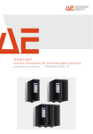
The thyro
switch 3P can be installed horizontally or vertically. The integrated fan controls the air flow,
so that nearly all the warm air produced is emitted in one direction. At maximum load, a temperature increase
of max. 30°C for type 70A and of 35°C for type 100A can be expected. If temperature sensitive components
are used, such as cable ducts, it is possible that cowls must be provided.
Temperature sensitive components installed in the vicinity have to be protected accordingly.
The safe distances specified must be observed.
• Fan side:
• Heat sink outlet:
>50mm
>150mm
With vertical installation it must be ensured that warm air is always emitted upwards. When installing several
thyro
switch 3P on top of one another, cowls should be used.
EDEBDA0105-1412-1_GB
Page 5 of 11
Version 1.0
thyro
User Manual
5
Connection
With a phase compensation the THYRO
SWITCH 3P must be selected after the line-to-line voltage, i.e.:
- 1 phase compensation in the 690V/400V - net needs thyro
- 1 phase compensation in the 400V/230V - net needs thyro
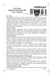
5.1
switch 3P
switch 3ph-690/400-50-100
switch 3ph-400/230-50-100
Alternating current compensation against zero-leaders
EDEBDA0105-1412-1_GB
Switching example for 3 alternating current stages between L1 and N.
Version 1.0
Page 6 of 11
thyro
5.2
switch 3P
User Manual
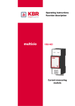
Alternating current compensation phase against phase (only in the 400/230V Net)
Switching example for 3 alternating current stages between L1 and L2 / L2 and L3 / L3 and L1.
EDEBDA0105-1412-1_GB
Page 7 of 11
Version 1.0
User Manual
5.3
thyro
switch 3P
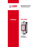
Three-phase current compensation 690V
Attention! The neutral wire must be attached and currentload-carrying.
EDEBDA0105-1412-1_GB
The gating for three-phase current compensation takes place at the same time on all 3 control inlets (1-3).
Version 1.0
Page 8 of 11
thyro
switch 3P
User Manual
For the connection of the load current with insulated crimping cable lugs with 8mm rings, terminal studs are
envisaged that must be tightened with a torque of 5.5 - 6Nm. The cable lugs must be exactly vertical to the
conducting plate. When laying leads, you should ensure that the connection leads are not heated up directly
by the exhaust from the heat sinks. As load fuses, fuse units for the protection of semiconductors must be used.
Project planning of their size must be made according to the connected capacitive load. You must ensure that
the equipment grounding conductor is connected correctly. The equipment grounding conductor connection in
the form of an M6 hexagon bolt is located on the heat sink beneath the connections for the capacitor and is
labeled with the PE conductor sign
.
For reactor-protected equipment it is absolutely essential that the thyro
before inductor and capacitor.
switch 3P is connected in series
Terminal 4 (+):
3 (+)
2 (+)
1 (-)
Thy 1
Thy 2
Thy 3
in accordance with connection
(see design on page 6, 7 and 8)
Terminal 5 and 6:
The supply voltage 207-253V AC with 50 or 60Hz is connected to terminals 5 and 6.
(see design on page 6, 7 and 8)
6
Commissioning
1. Check the correct connections of the thyro
switch 3P
2. Attach plastic housing
3. Switch on supply voltage ("Power" LED lights up)
4. Possible test of gating by the controller ("Control" LED lights up and fan starts up)
Control on the left
LED on the left
(Thy 1) Fan on the left starts up
(Terminal 1-4)
Control in the center LED in the center (Thy 2) F an in the right starts up
(Terminal 2-4)
Control on the right LED on the right
(Terminal 3-4)
Note:
(Thy 3) Fan on the right starts up
The operational current may only be released for the initial commissioning if
no gating takes place, that is, the thyro
switch 3P is switched off.
6. Connecting operational current
7. Release controller (for gating and correct function, "Power 1" and "Power 2/3", "Control 1-3", "Thy 1",
"Thy 2" and "Thy 3" light up)
EDEBDA0105-1412-1_GB
Page 9 of 11
Version 1.0
thyro
User Manual
7
switch 3P
Power limitation depending on ambient temperature
Not required.
8
Type Overview
Type
Artikelnummer
Voltage
Frequency Current
thyro
switch 3ph-690/400-50-100
V108-20-0001
690V/400V Y/Δ
50Hz
100A*
thyro
switch 3ph-690/400-60-100
V108-20-0002
690V/400V Y/Δ
60Hz
100A
thyro
switch 3ph-690/500-50-70
V108-20-0003
690V/500V Y/Δ
50Hz
70A
thyro
switch 3ph-690/500-60-70
V108-20-0004
690V/500V Y/Δ
60Hz
70A
thyro
switch 3ph-400/230-50-100
V108-20-0005
400V/230V Y/Δ
50Hz
100A*
thyro
switch 3ph-400/230-60-100
V108-20-0006
400V/230V Y/Δ
60Hz
100A
thyro
switch 3ph-240/140-50-100
V108-20-0007
240V/140V Y/Δ
50Hz
100A
thyro
switch 3ph-240/140-60-100
V108-20-0008
240V/140V Y/Δ
60Hz
100A
* Standard
Special voltages and currents on request.
9
Declaration of Conformity
ENGLISH CE DECLARATION OF CONFORMITY
We declare that we have sole responsibility that this product (see table) meets the regulations of Directives 73/
23/EEC and 89/336/EEC* and complies with the following standards or reference documents:
EN 61010-1/B2:2004;
EN 61000-6-3:2002;
EN 61000-6-4:2002
EDEBDA0105-1412-1_GB
EN 61010-1:2001;
EN61010-1/B1:2002;
EN 61000-6-1:2002; EN 61000-6-2:2002;
Version 1.0
Page 10 of 11
thyro
switch 3P
User Manual
10 Notes
EDEBDA0105-1412-1_GB
Page 11 of 11
Version 1.0