1
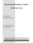
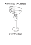
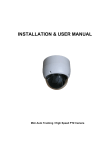
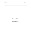
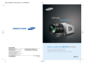
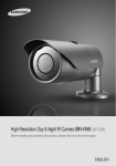
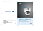
High Strength
Zoom
10X
High-Resolution 10X Vandal-Proof Dome Camera SVD-4300 User’s Manual
SALES NETWORK
•
SAMSUNG TECHWIN CO.,LTD.
145-3, Sangdaewon-dong, Jungwon-gu, Seongnam-si, Gyeonggi-do, 462-120, Korea
TEL : +82-31-740-8151~8 FAX : +82-31-740-8145
•
SAMSUNG TECHWIN AMERICA,LTD.
1480 Charles Willard St. Carson, CA 90746, UNITED STATES
TEL : +1-310-632-1234 FAX : +1-310-632-2195
•
SAMSUNG OPTO-ELECTRONICS UK,LTD.
Samsung House, 1000 Hillswood Drive, Hillswood Business Park
Chertsey Surrey KT16 OPS
TEL : +44-1932-45-5308 FAX : +44-1932-45-5325
Thank you for purchasing a SAMSUNG CCD CAMERA.
Before attempting to connect or operate this product,
please read these instructions carefully and save this manual for future use.
www.samsungtechwin.com
www.samsungcctv.com
P/No. : Z6806-0750-01D
VAN 08. 12
ENGLISH
Before operating the camera, confirm the camera model and proper input power
voltage. In order to that you can understand this manual thoroughly, we'll introduce
our model description.
■ SVD-4300 SERIES
•NTSC MODEL
SVD-4300(W)N
•PAL MODEL
SVD-4300(W)P
■ MODEL DESCRIPTION
• SVD-4300(W)X
_ _
SIGNAL SYSTEM
CAMEA COLOR
• SIGNAL SYSTEM
N NTSC MODEL
PAL MODEL
P
• CAMERA COLOR
SILVER COLOR
IVORY COLOR
W
The lightning flash with an arrowhead symbol, within an equilateral triangle is
intended to alert the user to the presence of uninsulated “dangerous voltage”
within the product's enclosure that may be of sufficient magnitude to
constitute a risk of electric shock to persons.
The exclamation point within an equilateral triangle is intended to alert the user
to the presence of important operating and maintenance (servicing)
instructions in the literature accompanying the appliance.
INFORMATION -This equipment has been tested and found to comply with limits
for a Class A digital device, pursuant to part 15 of the FCC Rules. These limits are
designed to provide reasonable protection against harmful interference when the
equipment is operated in a commercial environment. This equipment generates,
uses, and can radiate radio frequency energy and, if not installed and used in
accordance with the instruction manual, may cause harmful interference to radio
communications.
Operation of this equipment in a residential area is likely to cause harmful
interference in which case the user will be required to correct the interference at
his own expense.
WARNING - Changes or modifications not expressly approved by the manufacturer
could void the user’s authority to operate the equipment.
WARNING - To prevent electric shock and risk of fire hazards:
Do NOT use power sources other than that specified.
Do NOT expose this appliance to rain or moisture.
This installation should be made by a qualified service person and
should conform to all local codes.
Features
A/F 10x Optical Zoom
Day & Night
The built-in SVD-4300 optical zoom lens is a
highly durable component. It features auto
focus, auto iris, and zoom functions.
The camera automatically determines whether
it is night time or day time, selecting operating
mode automatically. The camera operates in
color mode during day light conditions and BW
mode in night conditions for clearer identification.
SSNR (Samsung Super Noise
Reduction)
By using built-in SSNR function manufactured
by SAMSUNG TECHWIN, the amount of low
illuminance noise has been significantly
reduced, and the signal-to-noise ratio (S/N)
as well as horizontal resolution have been
improved, resulting in a clear and sharp
image display even in the dark.
High Sensitivity
The built-in high sensitivity COLOR CCD
enables a clear image even in 0.005Lux
(Sens-up, color) or lower illumination.
High Resolution
Featuring 500TV line horizontal resolution in
color mode and 570TV line horizontal resolution
in BW mode, the camera features Sony's
410,000 pixel CCD and captures clean,
noiseless, high-quality images.
IP66 Approved / Dust and Rain
Resistant
With dust and rain resistant design, the camera
can be installed outside under building eaves or
places that are exposed to the dust and rain.
RS-485 Function
The camera, using a RS-485 communication
can remote control relate to ZOOM/FOCUS
and OSD menu functions.
Sub Monitor Function
The sub monitor function enables easy
adjustment of the camera angle within the
monitoring range during its installation.
3-Axis camera mechanism
The SVD-4300 is especially incredibly flexible to
install with its 3-axis camera construction,
which makes the camera wall or slope mountable.
Miscellaneous Functions
Other miscellaneous functions of the camera
include privacy zone masking, digital zoom, line
lock synchronization(INT/LL), freeze, horizontal
inversion, and user-configured presets.
Samsung Techwin cares for the environment at all product manufacturing
stages to preserve the environment, and is taking a number of steps to
provide customers with more environment-friendly products.The Eco mark
represents Samsung Techwin s will to create environment-friendly products,
and indicates that the product satisfies the EU RoHS Directive.
Warnings & Cautions
This information is provided to ensure your safety and to prevent any losses,
financial or otherwise. Please read it carefully and use the product accordingly.
* For product inquiries, please contact the retail shop where you bought the camera. The use of
equipment such as an aerial ladder while providing after-sales service shall be at your expense.
Warning/Attention/Special Mark Messages
Ignoring this information may result in material loss and/or serious
personal injuries including death.
Indicates “Never Allowed.”
Indicates “No Disassembling.”
Indicates Must Observe.
Contents
Precautions
8
Components and Accessories
10
Overview
11
• CAM TITLE
18
• WHITE BALANCE
21
• BACKLIGHT
22
23
24
• MOTION DETECTION
• FOCUS
• EXPOSURE
• SPECIAL
• RESET
Connection
Connecting To Monitor
Connecting To Power
RS-485 communication control
Operating Your Camera
Menu Configuration
Menu Setup
13
• EXIT
29
34
39
39
13
14
15
16
16
17
Troubleshooting
40
Specification
41
Dimension
43
Precautions
Do not install the camera in
extreme temperature conditions.
Do not install or use the camera in an
environment where the humidity is high.
Only use the camera under conditions
where temperatures are between
-10˚C and +50˚C. Be especially careful
to provide ventilation when operating
under high temperatures.
It can cause the image quality to be
poor.
Do not drop the camera or subject
them to physical shocks.
It can cause malfunctions to occur.
Never keep the camera face to
strong light directly.
It can damage the CCD.
Do not expose the camera to
radioactivity.
Do not install the camera under
unstable lighting conditions.
Do not touch the front lens of the
camera.
If it is exposed to radioactivity, For
heated CCD, it will be out of order.
Notes
Severe lighting change or flicker can
cause the camera to work improperly.
COLOR CCD CAMERA
It is one of the most important parts
of the camera. Be careful not to be
stained by fingerprint.
8
User’s Manual
• If the camera is exposed to spotlight or object reflecting strong light, smear or
blooming may occur.
• Please check that the power satisfies the normal specification before connecting
the camera.
COLOR CCD CAMERA
9
User’s Manual
Components and Accessories
Overview
1. SVD-4300
2. Instruction Manual
3. Quick Install Guide
4. Wrench
5. Ø5 Tapping Screws 4EA
6. Template
7. Installation Video Output Cable
COLOR CCD CAMERA
10 User’s Manual
COLOR CCD CAMERA
11 User’s Manual
Overview
Connection
Pan Base
control panning angle of camera
Rotate Base Holding Screw
fix rotated position
Rotate Base
control rotating angle of camera
Pan Base Holding Screws (Color : Silver)
fix panned position
Auto Focus 10x Zoom Lens Module.
SET button
To access the main setup menu. Pressing the “SET” button locks the zoom control
functions of these buttons and prompts the main setup menu.
AF button
To activate auto focus just once.
UP (WIDE button)
To move the arrow indicator to up.(To widen the view : ZOOM OUT)
DOWN(TELE button)
To move the arrow indicator to down (To close in on a far object: ZOOM IN)
LEFT (F-NEAR button)
To move the arrow indicator to left. (To see a near object clearly)
RIGHT (F-FAR button)
To move the arrow indicator to right. (To see a far object clearly)
Video Output Terminal to Monitor
Power Input Jack
Video Output Jack
RS-485 Control Cable
The detailed description refers to p15
Dome Cover
Shield Case
Connecting to Monitor
Connect the VIDEO-OUT jack to the VIDEO-IN jack of monitor.
CCTV Camera
Monitor
• As the connecting method varies with the instruments, refer to the manual
supplied with the instrument.
• If necessary, you can connect the monitor to the REMOTE jack on the back of
your camera.
• Only connect the cable when the power is turned off.
• Set the 75Ω / Hi-Z selection switch as shown below if you have an intermediate
device.
Intermediate
End monitor
Notes
• The zoom postion is saved after 5 seconds when you set zoom function.
COLOR CCD CAMERA
12 User’s Manual
CCTV Camera
COLOR CCD CAMERA
13 User’s Manual
Connection
Connecting to Power
RS-485 communication control
Use AC 24V / 300mA or DC 12V / 500mA power source.
Connecting to RS-485 Control Cable
CONTROL CABLE
RED (TRX+)
WHITE(TRX-)
Using a RS-485 communication, it will be able to control the ZOOM/FOCUS and
OSD menu at the SAMSUNG TECHWIN System Controller or DVR.
(1) The case which it controls from the PC
Using a RS-485 converter, It connects to RS-485 control cable outside camera
and serial cable
For DC Power Type
• For DC power as the voltage drop according to the length of the cable in the
above table, a camera may malfunction if there is an excessively long cable run.
Resistance of copper wire [at 20C˚ (68˚F)]
#24(0.22mm2)
#22(0.33mm2)
#20(0.52mm2)
#18(0.83mm2)
Resistance ( Ω / m)
0.078
0.050
0.030
0.018
Voltage Drop (V/m)
0.028
0.018
0.011
0.006
Copper wire size (AWG)
SPEC
RS-485+
RS-485-
* Voltage for camera operation: 12V DC ±10%
* Voltage drops in the above table are variable according to types of cable manufacturer.
Notes
EX) SERIAL PORT OF THE PC(COM1) — SERIAL CABLE -- RS-485 CONVERTER
-- RS-485 CONTROL CABLE
(2)The case which it controls from the DVR or System Controller
It connects the RS-485 control cable in the connection terminal of 485 control
boards which are connected with the DVR or System Controller.
485 CONTROL BOARD CONNECTION TERMINAL
(+)CONNECTION TERMINAL
(-)CONNECTION TERMINAL
RS-485 CONTROL CABLE
RED (TRX+)
WHITE(TRX-)
Notes
• Be sure to connect power only after all the installation is complete.
• Note that AC or DC adaptor is not supplied with camera.
• Use the UL listed, class 2 power transformer of AC 24V adaptor.
• Ground should be connected to the GND terminal.
COLOR CCD CAMERA
14 User’s Manual
• When you construct external control systems for a camera control, please use to
the SAMSUNG TECHWIN PROTOCOL or PELCO-D PROTOCOL.
• When you connecting to RS-485 control cable, please peel off the outer skin inside
the RS-485 control cable.
COLOR CCD CAMERA
15 User’s Manual
Operating Your Camera
Menu Configuration
Menu Setup
Use the six buttons on back of the camera.
MAIN SETUP MENU
SET button
CAM TITLE
•
OFF
•
ON
WHITE BALANCE
•
ATW(OUTDOOR)
•
AWC
BACKLIGHT
•
OFF
•
LOW
•
HIGH
MOTION DET
•
OFF
•
ON
FOCUS
•
MODE
•
ZOOM TRK
•
ZOOM SPEED
•
D-ZOOM
•
DISP ZOOM MAG
•
ZOOM POS INIT
•
LENS INIT
•
SMART ZOOM
•
END
•
BRIGHTNESS
•
IRIS
•
SHUTTER
•
AGC
•
SSNR
•
SENS-UP
•
END
•
USER PRESET
•
PRIVACY
•
DAY/NIGHT
•
SYNC
•
COMM ADJ
•
IMAGE ADJ
•
END
EXPOSURE
SPECIAL
RESET
SET
•
MANUAL
•
MIDDLE
LEFT button
AF button
RIGHT button
UP button
DOWN button
1. Press the SET button to access the main setup mode.
• Main setup menu is displayed on the monitor screen.
MAIN SETUP
CAM TITLE
OFF
WHIET BAL
ATW
BACKLIGHT
OFF
MOTION DET
OFF
FOCUS
EXPOSURE
SPECIAL
RESET
EXIT
EXIT
2. Select the desired feature using the UP or DOWN button.
• Each pressing of the UP or DOWN button moves the indicator to the next
or previous feature.
• Move the arrow indicator to the desired feature item.
COLOR CCD CAMERA
16 User’s Manual
COLOR CCD CAMERA
17 User’s Manual
Operating Your Camera
Select feature using the UP
or DOWN button.
3. Press SET button.
MAIN SETUP
CAM TITLE
OFF
WHIET BAL
ATW
BACKLIGHT
OFF
MOTION DET
OFF
FOCUS
EXPOSURE
SPECIAL
RESET
EXIT
Change the status using the
LEFT or RIGHT button.
3. Change the status of the selected feature using the LEFT or RIGHT button.
4. When completed, move the arrow indicator to 'EXIT' and press the SET button.
Notes
• Features marked with a have an accessible submenu.
• Access the submenu by pressing the SET button.
4. You can enter up to 15 characters.
Move the cursor to the character entry field using the LEFT or RIGHT
button.
Use UP, DOWN, LEFT, and RIGHT buttons to select a desired character.
CAM TITLE
Use this feature to designate a name for the camera, which will display on the
monitor screen.
1. Press the SET button to display the main setup menu and move the arrow
indicator to 'CAM TITLE' using the UP or DOWN button.
2. Set 'CAM TITLE' to 'ON' using the LEFT or RIGHT button.
Notes
• If the CAM TITLE feature is set to 'OFF',
the name will not displayed in the monitor.
COLOR CCD CAMERA
18 User’s Manual
MAIN SETUP
CAM TITLE
OFF
WHIET BAL
ATW
BACKLIGHT
OFF
MOTION DET
OFF
FOCUS
EXPOSURE
SPECIAL
RESET
EXIT
Press the SET button to confirm selection of the blinking character. The
character is then saved, and the cursor in the entry field moves to the
next position.
Repeat steps through until the desired name has been entered.
Notes
• Correcting Mistakes
Move the cursor to 'CLR' and press the SET button to clear the entire entry.
To modify one character, use or to position the cursor above the character
to be modified and click the SET button after selecting the character to enter.
COLOR CCD CAMERA
19 User’s Manual
Operating Your Camera
5. Select on screen position of the CAM TITLE.
Move the cursor to 'POS' and press SET button.
WHITE BALANCE CONTROL
Your camera provides three 'WHITE BAL' control modes for your choosing in
adjusting the white balance.
1. Press the SET button to access the main setup menu and move the indicator
to 'WHITE BAL' using the UP or DOWN button.
2. Set 'WHITE BAL' using the LEFT or RIGHT button.
The CAM TITLE is displayed on the top-left of the monitor screen.
(Default position)
FRONT DOOR
MAIN SETUP
CAM TITLE
OFF
WHIET BAL
ATW
BACKLIGHT
OFF
MOTION DET
OFF
FOCUS
EXPOSURE
The three white balance control modes are as follows :
to Locate, then SET
Select the position by using the 4-directional buttons, then press the SET
button to confirm the position.
FRONT DOOR
to Locate, then SET
6. When completed, move the cursor to 'END' and press SET button.
COLOR CCD CAMERA
20 User’s Manual
ATW(Auto Tracking White Balance):
• OUTDOOR: This mode can be used within the color temperature range 1800~10500˚K
(Ex: fluorescent light, outdoor, sodium vapor lamp or inside tunnels)
• INDOOR : This mode can be used within the color temperature range 3000K~10500˚K.
AWC(Auto White balance Control):
The white balance is automatically adjusted in a specific environment. In order to
obtain the best result, press the SET button while the camera focuses on white
paper. If the environment including the light source is changed, you have to adjust
the white balance again.
Manual:
To fine adjust, select the Manual mode. You can increase or decrease the red or
blue factor while monitoring the difference on the screen. Set to 'MANUAL' mode
and press the SET button. Increase or decrease the value for red(R-Gain) and
blue(B-Gain), watching the color of the picture, and press the SET button when you
obtain the best color.
COLOR CCD CAMERA
21 User’s Manual
Operating Your Camera
Notes
MOTION DETECTION
• Proper White Balance may not be obtained under the following conditions.
When the scene contains mostly high color temperature object, such as a blue
sky or sunset.
When the scene is dim.
If your camera directly faces a fluorescent lamp or is used in an environment of
varying lighting conditions.
BACKLIGHT
When there is a strong backlight behind the object, clear images of the background
as well as the object can still be obtained by using the BACKLIGHT function.
1. Please position the arrow to point to 'BACKLIGHT' on the SETUP menu by
using the UP and DOWN buttons.
2. Please select the mode you wish to operate by pressing the LEFT or RIGHT
button.
MAIN SETUP
CAM TITLE
OFF
WHIET BAL
ATW
BACKLIGHT
OFF
MOTION DET
OFF
FOCUS
HIGH/MIDDLE/LOW: You can adjust the sensitivity of Backlight Compensation.
OFF: BACKLIGHT function does not operate.
Backlight ON
COLOR CCD CAMERA
This product has a feature that allows you to observe movements of objects in
4 different areas on the screen, and the words ‘MOTION DETECTED’ appear on
the screen when movement is detected; hence a single individual can conduct
supervision efficiently. The camera detects an object’s movement by sensing
disparity of outline, and level of brightness and color.
•Please press the SETUP button.
-OFF: MOTION DETECTION mode is cancelled.
-ON: Any motion in the selected areas is observed.
•Please press the SETUP button.
-OFF: MOTION DETECTION mode is cancelled.
-ON: Any motion in the selected areas is observed.
•Please select the area you wish to observe from the 4 areas in AREA SEL mode.
•Please select ON mode for the chosen area.
•Please adjust the size of the area to be observed by using the UP, DOWN, LEFT
or RIGHT button.
•Please press the SETUP button to save changes and complete the setting.
Notes
Tips on Using the Motion Detection Feature
• The feature may not function properly under flickering light conditions.
• The camera interprets sudden changes in lighting and subsequent change in
brightness of an object as motion.
• With the feature enabled, other algorithms may require additional time to operate
than usual.
• This system does not guarantee prevention of fire or theft. The manufacturer
shall not be held responsible for any accident or damage incurred.
Backlight OFF
22 User’s Manual
COLOR CCD CAMERA
23 User’s Manual
Operating Your Camera
FOCUS
MAIN SETUP
CAM TITLE
OFF
WHIET BAL
ATW
BACKLIGHT
OFF
MOTION DET
OFF
FOCUS
EXPOSURE
SPECIAL
1. Press the SET button to access the main setup manu and then position the
indicator over FOCUS using the UP or DOWN button.
2. Press the SET button.
MODE: You can select the most suitable zoom mode. Move the arrow indicator to
‘MODE’ using UP or DOWN button.
FOCUS SETUP
MODE
ZOOM TRK
ZOOM SPEED
D-ZOOM
DISP ZOOM MAG
AUTO
ON
FAST
OFF
OFF
•AUTO : Select AUTO and press the SET button to confirm. Increase or decrease
optical zoom (ZOOM) or digital zoom (DZOOM) positions using the UP or DOWN
button while verifying the changes on
screen. Enabling D-ZOOM (ON) means that
digital zoom will activate once optical zoom
ends. Focus is automatically adjusted with
moving zoom.
COLOR CCD CAMERA
24 User’s Manual
•ONE PUSH : Focus is automatically adjusted just once,
after zoom position is changed. Select '
ONE PUSH' and press the SET button to
confirm. Increase or decrease optical
zoom (ZOOM) or digital zoom (D-ZOOM)
positions using the directional buttons
while verifying the changes on screen. Press the SET button once
desired image quality is obtained.
•MANUAL : Select 'MANUAL' and press the SET button
to confirm. Increase or decrease optical zoom
(ZOOM) or digital zoom (D-ZOOM) positions
using the directional buttons while verifying
the changes on screen. Press the SET button
once desired image quality is obtained. Focus
can be manually adjusted, independent of moving zoom.
ZOOM TRK: You can select to use ‘ZOOM TRK’. Move the arrow indicator to ‘ZOOM
TRK’ using UP or DOWN button. Set ‘ZOOM TRK’ to on using LEFT or
RIGHT button.
FOCUS SETUP
MODE
ZOOM TRK
ZOOM SPEED
AUTO
ON
FAST
ZOOM SPEED: Configure zoom tracing speed using this feature. Position the indicator
over 'ZOOM SPEED' using the UP or DOWN button and then set to
desired mode using the LEFT or RIGHT button.
FOCUS SETUP
MODE
ZOOM TRK
ZOOM SPEED
D-ZOOM
COLOR CCD CAMERA
AUTO
ON
FAST
OFF
25 User’s Manual
Operating Your Camera
•FAST: To move zoom fast.
•SLOW: To move zoom slowly.
Notes
ZOOM POS INIT: Configure zoom position using this feature. Position the
indicator ove 'ZOOM POS INIT' using the LEFT or RIGHT button.
FOCUS SETUP
• The 'ZOOM SPEED' mode cannot be used if 'MODE' is set to 'AUTO' and 'ZOOM
TRK' is 'ON'.
MODE
ZOOM TRK
ZOOM SPEED
D-ZOOM
DISP ZOOM MAG
ZOOM POS INIT
LENS INIT
D-ZOOM: Configure magnification limit from x2~x10 using this feature. Position the
indicator over 'D-ZOOM' using the UP or DOWN button. Set 'D-ZOOM' to
'ON' and press the SET button to confirm.
FOCUS SETUP
MODE
ZOOM TRK
ZOOM SPEED
D-ZOOM
DISP ZOOM MAG
AUTO
ON
FAST
ON
OFF
· Set 'ZOOM LIMIT' to the desired level using the LEFT or
RIGHT button.
AUTO
ON
FAST
OFF
OFF
ON
Notes
• Preset setting has priority over a ZOOM POS INIT setting.
LENS INIT : Use this feature to initialize the lens(1x, WIDE). Position the indicator
over LENS INIT. using the UP or DOWN button. Press the SET button
to confirm.
FOCUS SETUP
DISP ZOOM MAG: Use this feature to display the current zoom magnification level on
screen. Position the indicator over 'DISP ZOOM MAG' using the UP
or DOWN button. Then set to ON using the LEFT or RIGHT button.
FOCUS SETUP
MODE
ZOOM TRK
ZOOM SPEED
D-ZOOM
DISP ZOOM MAG
COLOR CCD CAMERA
AUTO
ON
FAST
OFF
ON
26 User’s Manual
MODE
ZOOM TRK
ZOOM SPEED
D-ZOOM
DISP ZOOM MAG
ZOOM POS INIT
LENS INIT
SMART ZOOM
END
COLOR CCD CAMERA
AUTO
ON
FAST
OFF
OFF
OFF
27 User’s Manual
Operating Your Camera
SMART ZOOM :
'SMART ZOOM' is acted by motion perception. 'SMART ZOOM' acts zoom as
'TARGET ZOOM' that is established if motion is sensed. (Condition : when all
'MOTION DET MODE' and 'SMART ZOOM MODE' are 'ON') 'SMART ZOOM'
returns as 'START ZOOM' after delay as 'DWELL TIME' establishing after action.
FOCUS SETUP
MODE
ZOOM TRK
ZOOM SPEED
D-ZOOM
DISP ZOOM MAG
ZOOM POS INIT
LENS INIT
SMART ZOOM
END
AUTO
ON
FAST
OFF
OFF
OFF
You can change 'SMART ZOOM' function
establishment if press SET button after select 'SMART
ZOOM' article in FOCUS SETUP MENU.
•MODE : You can establish mode using left or right button
•START ZOOM : You use left or right button in
'START ZOOM' article you can select
zoom position to return after
'SMART ZOOM' action from 1 times to 9 times.
•TARGET ZOOM : When uses one side or right button in 'TARGET ZOOM' article
and senses motion, you can select zoom position to act from 2
times to 10 times.
•DWELL TIME : You use left or right button in 'DWELL TIME' article. You can choose
time to delay before return to 'START ZOOM' position after zoom
motion at 'TARGET ZOOM' position from 1 second to 20 seconds.
EXPOSURE
EXPOSURE SETUP
BRIGHTNESS
IRIS
SHUTTER
AGC
SSNR
SENS-UP
END
25.......
AUTO
--NORMAL
LOW
OFF
1. Press the SET button to access the main setup menu and then position the
indicator over 'EXPOSURE' using the UP or DOWN button.
2. Press the SET button to confirm.
BRIGHTNESS: Use this feature to adjust image brightness. Position the
indicator over 'BRIGHTNESS' using the UP or DOWN button.
Then increase or decrease brightness level using the LEFT or
RIGHT button while verifying the changes on screen. Set END
once desired level is obtained.
EXPOSURE SETUP
BRIGHTNESS
IRIS
SHUTTER
AGC
SSNR
SENS-UP
END
25.......
AUTO
--NORMAL
LOW
OFF
END: To revert to the main setup menu.
COLOR CCD CAMERA
28 User’s Manual
COLOR CCD CAMERA
29 User’s Manual
Operating Your Camera
IRIS: Set 'IRIS' to 'AUTO' or 'MANUAL'. Position the indicator over 'IRIS' using the UP
or DOWN button and then select the desired iris mode using the LEFT or RIGHT
button.
EXPOSURE SETUP
BRIGHTNESS
IRIS
SHUTTER
AGC
25.......
AUTO
--NORMAL
•AUTO: The iris is automatically activated upon illumination.
•MANUAL: Manual iris configuration. Set 'IRIS' to 'MANUAL' using the LEFT or
RIGHT button and then press the SET button. Increase or decrease iris
level using the LEFT or RIGHT button while verifying the changes on screen.
•A.FLK (NTSC: 1/100, PAL: 1/120): Flicker-free mode
•ESC: Automatic shutter speed setting (optimal)
•MANUAL: Manual shutter speed setting
2. If you choose ‘MANUAL’, select the optimal shutter speed.
· In MANUAL mode, the optimal shutter speed needs to be designated. Select from 1/60
to 1/120,000 (NTSC) or from 1/50 to 1/120,000 (PAL).
* 'Sens-Up' mode can be configured manually (2x to 128x).
· Verify changes made to the shutter speed by referencing to changes in on screen
brightness.
3. Press the SET button to complete.
Notes
SHUTTER : Control image brightness by adjusting shutter speed.
1. Position the indicator over 'SHUTTER' using the UP or DOWN button. Then select
the desired shutter mode (A.FLK, ESC, MANUAL) using the LEFT or RIGHT button.
EXPOSURE SETUP
BRIGHTNESS
IRIS
SHUTTER
AGC
SSNR
COLOR CCD CAMERA
• Image may become unstable if the camera is set to 'ESC' mode and faces a strong
fluorescent light.
• Under 'ESC' mode, the brightness can be adjusted using the LEFT or RIGHT button.
• The WDR feature is not available under MANUAL mode.
• Sens-up is disabled under 'MANUAL' or 'A.FLK' mode.
25.......
AUTO
--NORMAL
LOW
30 User’s Manual
COLOR CCD CAMERA
31 User’s Manual
Operating Your Camera
AGC (Auto Gain Control): For brighter images.
1. Position the indicator over 'AGC' using the UP or DOWN button.
2. Set 'AGC' to the desired mode using the LEFT or RIGHT button.
•HIGH
: Wide range gain value adjustment
•NORMAL : Normal range fain value adjustment.
•OFF
: Disabled
EXPOSURE SETUP
BRIGHTNESS
IRIS
SHUTTER
AGC
SSNR
SENS-UP
25.......
AUTO
--NORMAL
LOW
OFF
Notes
• Changing 'AGC' setting from NORMAL to HIGH results in greater sensitivity, as well
as on screen noise.
• Setting 'AGC' to OFF locks 'SSNR' configuration.
SENS-UP : This feature ensures clear images at night or under low lighting
conditions.
1. Position the indicator over 'SENS-UP' using the UP or DOWN button.
2. Set 'SENS-UP' to the desired mode using the LEFT or RIGHT button.
•AUTO : Select this mode for use in night time or under low lighting conditions.
•OFF : Disabled
EXPOSURE SETUP
BRIGHTNESS
IRIS
SHUTTER
AGC
SSNR
SENS-UP
END
SSNR(Samsung Super Noise Reduction): On screen noise reduction.
1. Position the indicator over 'SSNR' using the UP or DOWN button.
2. Set 'SSNR' to the desired mode using the LEFT or RIGHT button.
•LOW : Low noise reduction
•MIDDLE : Medium noise reduction
•HIGH : High noise reduction
•OFF
: Disabled
EXPOSURE SETUP
BRIGHTNESS
IRIS
SHUTTER
AGC
SSNR
SENS-UP
COLOR CCD CAMERA
25.......
AUTO
--NORMAL
LOW
OFF
32 User’s Manual
25.......
AUTO
--NORMAL
LOW
OFF
Notes
• Once 'AUTO' mode is set, the user can configure Sens-Up limit by increasing
/decreasing the shutter speed (e.g.: x2,...,x32, x64,..., x128).
• Enabling Sens-Up increases camera sensitivity and may result in additional noise
and/or other phenomenons. This is normal.
COLOR CCD CAMERA
33 User’s Manual
Operating Your Camera
•PRESET NO : Up to eight different preset configurations are supported.
SPECIAL
SPECIAL SETUP
USER PRESET
OFF
PRIVACY
OFF
DAY/NIGHT
COLOR
SYNC
INT
COMM ADJ
IMAGE ADJ
END
USER PRESET SETUP
PRESET NO.
NO. 1
PRESET MODE
OFF
PRESET SAVE
PRESET CLEAR
END
PRESET DEFINED
•PRESET MODE: Configure initial settings under FOCUS, EXPOSURE, etc.
1. Press the SET button to access the main setup menu and then position the
indicator over 'SPECIAL' using the UP or DOWN button.
2. Press the SET button to confirm.
USER PRESET:
Preset user-designated configurations using this feature. Position the indicator
over 'USER PRESET' using the UP or DOWN button and then set to 'ON' using the
LEFT or RIGHT button. Press the SET button to confirm.
SPECIAL SETUP
USER PRESET
OFF
PRIVACY
OFF
DAY/NIGHT
COLOR
SYNC
INT
COMM ADJ
IMAGE ADJ
END
COLOR CCD CAMERA
34 User’s Manual
•PRESET SAVE: Save configured preset.
USER PRESET SETUP
PRESET NO.
NO. 1
PRESET MODE
OFF
PRESET SAVE
PRESET CLEAR
END
PRESET DEFINED
COLOR CCD CAMERA
35 User’s Manual
Operating Your Camera
•PRESET CLEAR: Clear configured preset.
USER PRESET SETUP
PRESET NO.
NO. 1
PRESET MODE
OFF
PRESET SAVE
PRESET CLEAR
END
PRESET DEFINED
•END: Revert to the SPECIAL SETUP menu.
•GROUP SEL : Choose up to eight groups. Each group can consist of four mask
areas.
•AREA SEL
: Configure eight mask areas.
•AREA MODE : Mask area display.
•MASK TONE : Adjust desired mask color level.
•TOP
: To move the mask area up.
•BOTTOM
: To move the mask area down.
•LEFT
: To move the mask area left.
•RIGHT
: To move the mask area right.
DAY/NIGHT: Select from COLOR, BW or AUTO modes.
USER PRESET SETUP
PRESET NO.
NO. 1
PRESET MODE
OFF
PRESET SAVE
PRESET CLEAR
END
PRESET DEFINED
PRIVACY: Mask privacy area using this feature. The mask area expand/contract
upon the zoom position.
SPECIAL SETUP
USER PRESET
OFF
PRIVACY
OFF
DAY/NIGHT
COLOR
SYNC
INT
COMM ADJ
COLOR CCD CAMERA
36 User’s Manual
SPECIAL SETUP
USER PRESET
OFF
PRIVACY
OFF
DAY/NIGHT
COLOR
SYNC
INT
COMM ADJ
IMAGE ADJ
END
•COLOR : Color mode.
•B/W : BW mode.
•AUTO1, 2 : The camera automatically detects lighting conditions and selects the
mode accordingly. Auto 1 mode is switched to IR Cut Filter more
lightning conditions than Auto 2.
Notes
• When selecting AUTO2 mode, the AGC is fixed at HIGH mode.
COLOR CCD CAMERA
37 User’s Manual
Operating Your Camera
SYNC : Two synchronization modes are available INTERNAL and EXTERNAL LINE-LOCK.
In LINE-LOCK mode, it synchronizes the camera’s video out signal to the external
SYNC signal.
SPECIAL SETUP
USER PRESET
OFF
PRIVACY
OFF
DAY/NIGHT
COLOR
SYNC
INT
COMM ADJ
IMAGE ADJ
•INT : Internal synchronization
•LL : External line-lock synchronization
· If you choose ‘LL’, you can adjust the desired phase.
Press the SET button.
· You can adjust the desired phase from 0 to 359.
Notes
• For NTSC models, the line-lock mode can be used if the external SYNC signal
frequency is at 60Hz.
• For PAL models, the line-lock mode can be used if the external SYNC signal
frequency is at 50Hz.
•CAM ID : Assign ID number to the camera. It is restricted available to set ID from
0 to 255.
•DISP CAM ID: Displays camera ID on top left corner of the screen.
•BAUD RATE : Configure baud rate from 2400bps, 4800bps, 9600bps, 19200bps,
38400bps and 57600bps.
•UART MODE : Configure parity bit to NONE, EVEN, or ODD. Data bit is set to 8bit,
and stop bit to 1bit. Set the UART MODE to EVEN if using the
Remote Controller.
•RET PKT
: Used to transfer a packet.
•END
IMAGE ADJ: Includes image quality or special function
factors.
•FREEZE
: Use this feature to freeze capture an
image.
•H-REV
: Use this feature to horizontally
inverse the screen.
•V-REV
: Use this feature to vertically inverse
the screen.
•SHARPNESS : Increasing this value sharpens object edges. Too high of a setting,
however, produces noise and may obscure the image.
•COLOR AGAIN : Adjusting this value affects the chroma level only; the burst level is
unaffected.
END: evert back to the USER PRESET menu.
COMM ADJ: Use this feature to select communication
protocol . Position the indicator over
'COMMUNICATION' using the UP or
DOWN button.
RESET
To reset your camera to factory default condition.
EXIT
To finish setup menu.
COLOR CCD CAMERA
38 User’s Manual
COLOR CCD CAMERA
39 User’s Manual
Troubleshooting
Specifications
Refer to the following table if you are experiencing trouble with your camera.
Contact an authorized technician if the table does not provide you with a
solution to the trouble.
Problem
Solution
No display
• Check the power cable and the wiring between the
camera and the monitor.
• Ensure proper video cable connection (Video Out
Jack).
Dim display
• The lens could be dirty. Clean with a soft, clean
piece of cloth.
• Adjust monitor settings.
• Adjust camera position if exposed to a strong light
source.
Dark display
• Adjust the monitor's contrast level.
• Set the intermediate device, if in use, to 75Ω/ Hi-z
(refer to p.13).
The camera is not functioning
properly and its surface is hot
• Check the power source for compliance with
specifications.
Motion Detection
feature is not active.
• Ensure that the feature is set to ON.
Uneven colors
Flickering
• Adjust and configure WHITE BAL.
• The camera may be facing the sun or a fluorescent
light. Adjust the position of the camera.
Can't select LL mode
• The camera may be connected to a DC power
source. Connect to an AC power source.
LL is not function
properly.
• Check external SYNC signal frequency (should be
60Hz for NTSC, 50Hz for PAL).
COLOR CCD CAMERA
40 User’s Manual
SVD-4300(W)N
P
O
W
E
R
C
C
D
O
P
T
I
C
S
S
y
n
c.
E
L
E
C.
Input Voltage
Input Current
Power Consumption
Size
Total Pixels
Effective Pixels
Optics
Min. Focus Distance
D. ZOOM
Angle Field of view
Scanning System
Synchronization
Frequency
Resolution
Video Output
S/N (Y signal)
Min. Illumination
Backlight Compensation
Day & Night
Gain Control
White Balance
Electronic shutter
speed
O.S.D
Motion Detection
SSNR
Focus
Zoom Movement Speed
IRIS Control
Lens Initialize
Camera Title
SVD-4300(W)P
AC24V(±10%), DC 12V(±10%)
290mA(Steady-state)
460mA(Zoom, Focus, Day&night motor operating)
DC12V/ AC24V - 3.5W Normal,
- 5.5W Max(Zoom, Focus, Day&Night motor operating)
1/4 inch, Interline Transfer CCD
811(H) x 508(V)
795(H) x 596(V)
768(H) x 494(V)
752(H) x 582(V)
10X, f=3.8 to 38.0mm(F1.8)
1,500mm
OFF/ON (X2 ~ X10)
H : Appr. 51.2˚(Wide) to 5.58˚(Tele)/V : Appr. 39.3˚(Wide) to 4.27˚(Tele)
2:1 Interlace
Internal / Line-Lock
H: 15.734KHz / V: 59.94Hz
H: 15.625KHz / V : 50.00Hz
500 TV Lines(Min.) : Color (WIDE) / 570 TV Lines(Min.) : B/W (WIDE)
CVBS : 1.0Vp-p/75Ω(VBS EXT)
50 dB (AGC Off, Weight ON)
[email protected], [email protected](Sens-up), Color/[email protected](B/W)
LOW/MIDDLE/HIGH/OFF Selectable
Auto1, Auto2, COLOR, B/W(ICR)
Normal, High, OFF Selectable
ATW (INDOOR(3,000K~10,500K), OUTDOOR (1,800K~10,500K))/AWC/MANUAL
AUTO (X128~1/60sec~1/120,000sec)
Sens-up and Sens-up Limit is
selectable, Flickerless
AUTO (X128~1/50sec~ 1/120,000sec )
Sens-up and Sens-up Limit is
selectable, Flickerless
Built-In
ON/OFF(4 Programmable Zone per Screen)
Low, Middle, High, Off
Auto / Manual / One push
1.67sec : Wide to Tele
1.75sec : Wide to Tele
Auto, Manual
Built-In
OFF/ON (Displayed 15 characters)
COLOR CCD CAMERA
41 User’s Manual
Specifications
Dimension
SVD-4300(W)N
Communication
E
L
E
C.
Privacy Function
FLIP
Preset
Operating
Temperature/Humidity
Dimension
Weight
Ø 148mm
SVD-4300(W)P
RS485 External Control(TRX+,TRX-) 2400bps, 4800bps, 9600bps, 19200bps,
38400bps and 57600bps selectable
SAMSUNG TECHWIN PROTOCOL AVAILABLE
PELCO-D PROTOCOL AVAILABLE
ON/OFF(32Zones, It consists of 8Group 4Programmable Zone per Screen)
Vertical, Horizontal, Vertical-Horizontal, OFF Selectable
8 Positions
-10˚C to +50˚C / 20% to 80% RH
126mm
Ø150 x 130mm(H)
1.4 kg
* SVD-4300WN, SVD-4300WP : Ivory color base model
83.5mm
85mm
COLOR CCD CAMERA
42 User’s Manual
COLOR CCD CAMERA
43 User’s Manual
46mm
85mm
85mm
DECLARATION OF CONFORMITY
Application of Council Directive(s)
89 / 336 / EEC
Manufacturer's Name
SAMSUNG TECHWIN CO., LTD
Manufacturer's Address
SAMSUNG TECHWIN CO., LTD
42, SUNGJU-DONG CHANGWON-CITY,
KYUNGNAM, KOREA, 641-716
European Representative Name
European Representative Address
Equipment Type/Environment
CCTV Camera
Model Name
SVD-4300P/WP
Beginning Serial NO.
S8040001
Year of Manufacture
2008. 12. 01
Conformance to
EN 50081-1 : 1992
EMC-Directive 89/336 EEC and 92/31/EEC
EN 50130-4 : 1996
We, the undersigned, hereby declare that the equipment specified above conforms
to the above Directive(s).
Manufacturer
SAMSUNG TECHWIN CO., LTD
Signature
Legal Representative in Europe
Signature
Full Name
HAN SEUG KIM
Full Name
Position
QUALITY CONTROL MANAGER
Position
Place
CHANGWON, KOREA
Place
Date
2008. 12. 01
Date
MEMO
MEMO