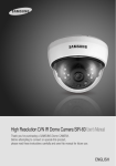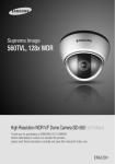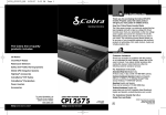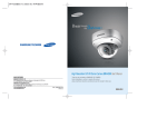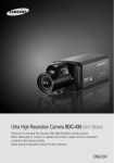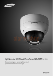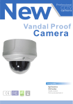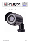
1
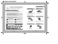
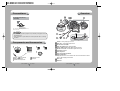
Outstanding 24-Hour image
580TVL / 700TVL
High Resolution Day & Night Dome Camera SID-460 User’s Manual
Thank you for purchasing a SAMSUNG CCD CAMERA.
Before attempting to connect or operate this product,
please read these instructions carefully and save this manual for future use.
SALES NETWORK
•
SAMSUNG TECHWIN CO., LTD.
145-3, Sangdaewon-dong, Jungwon-gu, Seongnam-si, Gyeonggi-do, 462-120, Korea
TEL : +82-31-740-8132~6 FAX : +82-31-740-8144
•
SAMSUNG OPTO-ELECTRONICS UK, LTD.
Samsung House, 1000 Hillswood Drive, Hillswood Business Park Chertsey, Surrey KT16 OPS
TEL : +44-1932-45-5308 FAX : +44-1932-45-5325
www.samsungtechwin.com
www.samsungcctv.com
P/No. : Z6806089401A
VAN 08. 03
ENGLISH
Before operating the camera, confirm the camera model and proper input power
voltage. In order to that you can understand this manual thoroughly, we'll introduce
our model description.
■ SID-460 SERIES
• NTSC MODEL
SID-460N
• PAL MODEL
SID-460P
■ MODEL DESCRIPTION
• SID-460X_
SIGNAL SYSTEM
• SIGNAL SYSTEM
N NTSC MODEL
PAL MODEL
P
The lightning flash with an arrowhead symbol, within an equilateral triangle is
intended to alert the user to the presence of uninsulated “dangerous voltage”
within the product's enclosure that may be of sufficient magnitude to
constitute a risk of electric shock to persons.
The exclamation point within an equilateral triangle is intended to alert the user
to the presence of important operating and maintenance (servicing)
instructions in the literature accompanying the appliance.
INFORMATION -This equipment has been tested and found to comply with limits
for a Class A digital device, pursuant to part 15 of the FCC Rules. These limits are
designed to provide reasonable protection against harmful interference when the
equipment is operated in a commercial environment. This equipment generates,
uses, and can radiate radio frequency energy and, if not installed and used in
accordance with the instruction manual, may cause harmful interference to radio
communications.
Operation of this equipment in a residential area is likely to cause harmful
interference in which case the user will be required to correct the interference at
his own expense.
WARNING - Changes or modifications not expressly approved by the manufacturer
could void the user’s authority to operate the equipment.
WARNING - To prevent electric shock and risk of fire hazards:
Do NOT use power sources other than that specified.
Do NOT expose this appliance to rain or moisture.
This installation should be made by a qualified service person and
should conform to all local codes.
Features
Contents
• Features
5
• Warnings & Cautions
6
• Components and Accessories
8
• Overview
9
• Installation
Sub Monitor Function
By adopting a diagonal 6mm(1/3") 410,000
(NTSC) pixel, 470,000(PAL) pixel SONY CCD,
the camera produces clear picture quality with
a horizontal resolution of 580 TV lines for color.
The sub monitor function enables easy
adjustment of the camera angle within the
monitoring range during its installation.
3-Axis camera mechanism
10
Installation
10
Adjust the panning and tilting, rotating while watching the monitor
12
• Connection
Ultra High Resolution
13
Connecting To Monitor
13
Connecting To Power
13
RS-485 communication control
14
• Operating Your Camera
15
Menu Configuration
15
Menu Setup
16
• Troubleshooting
30
• Specifications
32
• Dimension
33
Excellent Sensitivity
The SID-460 is especially incredibly flexible to install
with its 3-axis camera construction, which makes
the camera wall or slope mountable.
The built-in high sensitivity COLOR CCD
enable a clear image even in 0.15Lux(COLOR),
0.0006 Lux (Color, 256x Sens-up), 0.001 Lux
(B/W) or lower illumination.
Miscellaneous Functions
SSNR (Samsung Super Noise
Reduction) Function
HLC(High Light Compensation), SENS-UP,
FREEZE, FLIP (H/V-REV), D-ZOOM,
SHARPNESS, MOTION DETECTION and
PRIVACY functions are provided.
The high performance W-IV DSP chip
dramatically reduces the gain noise in digital
image processing, producing clear, sharp
images in low lighting environments.
RS-485 Communication
Control Support
Day&Night
Remote OSD menu control via an RS-485 interface
is supported.
The camera identifies whether it is day or night and
automatically switches to the appropriate mode,
depending on its environment. By day, the camera
switches to color mode in order to maintain optimal
color. At night, it switches to B/W mode so as to
obtain better picture definition.
OSD
The camera control is convenient by using 7
different foreign language O.S.D.
- NTSC : Korean, English, Spanish, Japanese
- PAL : English, French, German, Spanish, Italian,
Chinese
DIS (Digital Image Stabilizer)
The DIS function compensates for any camera
movement, to produce more stable pictures.
COLOR CCD CAMERA
5
User’s Manual
Samsung Techwin cares for the environment at all product manufacturing
stages to preserve the environment, and is taking a number of steps to
provide customers with more environment-friendly products.The Eco mark
represents Samsung Techwin s will to create environment-friendly products,
and indicates that the product satisfies the EU RoHS Directive.
Precautions
Do not install under extreme
temperature conditions.
Do not install in high humidity
environment.
Warnings & Cautions
This information is provided to ensure your safety and to prevent any losses, financial
or otherwise. Please read it carefully and use the product accordingly.
* For product inquiries, please contact the retail shop where you bought the camera. The use of equipment such
as an aerial ladder while providing after-sales service shall be at your expense.
* Separate the power plug when thunder crashes or lighting flashes.
* This product is support equipment for surveillance system. Therefore, we can't compensate for material loss
and/or personal injuries by robbery, fire, natural disaster or something like this type.
Use only under temperature conditions between
-10˚C and +50˚C. Provide good ventilation when
using in high temperature conditions.
May lower image quality.
Do not install under unstable
lighting conditions.
Avoid touching the camera lens.
Warning/Attention/Special Mark Messages
Ignoring this information may
result in material loss and/or
serious personal injuries including
death.
Ignoring this information may
result in material loss and/or a
slight injuries.
Indicates “Never Allowed.”
Indicates “No Disassembling.”
Severe lighting changes or flickering may hinder
normal camera operation.
The lens is the most important component of
the camera. Be careful not to smear it with
fingerprints.
Do not drop the camera or subject
it to physical shock.
May cause a product malfunction.
COLOR CCD CAMERA
6
User’s Manual
COLOR CCD CAMERA
Never keep the camera face to
strong light directly.
May damage the CCD.
7
User’s Manual
Overview
Precautions
Do not expose the camera to
radioactivity.
If it is exposed to radioactivity, For heated CCD, it
will be out of order.
Notes
• If the camera is exposed to spotlight or object reflecting strong light, smear or
blooming may occur.
• Please check that the power satisfies the normal specification before connecting
the camera.
Components and Accessories
SID-460
Instruction Manual
M4 Machine Screw 4EA
Installation Video Output Cable
COLOR CCD CAMERA
M4 Tapping Screw 4EA
Adapter plate
8
User’s Manual
Pan Base : control panning angle of camera
Rotate Base : control rotating angle of camera
X2.5 Vari-focal Lens Module
Rotate Base Holding Screw : fix rotated position
Pan Base Holding Screws (Color : Silver) : fix panned position
RS-485 Control Cable : The detailed description refers to p14
Power Input Connector
Video Output Jack
Video Output Terminal to Monitor
Function Setup Button
display the menu on the screen and move the cursor to four directions to confirm
status or after changing a selected item.
Dome Cover
Shield Case
COLOR CCD CAMERA
9
User’s Manual
Installation
Installation
When installing on a adapter plate
Notes
• The installation should be done by qualified service personnel or sysytem installers.
• If the ceiling material is not strong enough to hold the installation screws, the camera
may fall off. Reinforce the ceiling as needed.
An arrow for installing directions
adapter plate
1) Separate the dome cover by clockwise rotation.
2) Separate the shield case by pulling from the camera body.
Latch
* To install the dome cover on the camera
body, turn the latches in locking
direction as shown in the figure 1.
Locking direction
M4 tapping
screw (provided)
CAMERA
1) Place the bracket provided on the
installation surface and fix it with the M4
tapping screws (provided).
2) When placing the camera body on the plate,
insert the plate pin into the mounting hole
on the body as shown in figure-1 and fix it
by turning clockwise.
3) When placing the camera body on the plate,
make sure the power and the BNC cables
pass through their respective designated
holes.(When placing the cable through its
side, thread it through the hole at the
bottom.)
4) After installation and adjustment of the
camera are complete, secure the dome
cover by turning it clockwise.
[Figure-1]
Main Body
(Camera)
Locking
direction
Plate pin
Unlocking
direction
Locking direction
Dome cover
Unlocking direction
Shield Case
Unlocking direction
(Counterclockwise)
Locking direction
(Clockwise)
Dome cover
COLOR CCD CAMERA
10 User’s Manual
[Figure-1]
Notes
• Please locate an arrow on bracket for installing direction that you wish to observe Area
and then fix it with the M4 tapping screws.
COLOR CCD CAMERA
11 User’s Manual
Connection
Installation
Adjust the panning and tilting, rotating while watching the monitor
Connecting Monitor
Connect the VIDEO-OUT jack to the VIDEO-IN jack of monitor.
73˚
145˚
195˚
Monitor
170˚
Tilt Base
Rotate Base
CCTV Camera
Pan Base
• As the connecting method varies with the instruments, refer to the manual supplied
with the instrument.
• If necessary, you can connect the monitor to the REMOTE jack on the back of your camera.
• Only connect the cable when the power is turned off.
• Set the 75Ω / Hi-Z selection switch as shown below if you have an intermediate device.
-170˚
1) You can adjust camera to any direction by using Pan, Tilt, Rotate mechanism.
• Pan Base moves by 170˚ to each side direction and 340˚ on the whole.
• Tilt Base covers total 146˚ angle(73˚ to each side).
• Angle range of Rotate Base is the same as that of Pan Base. But One side range is 195˚
and another is 145˚.
2) Methods of adjustment
•The case of wall installation
After mounting the camera on a wall, adjusting the panning angle so that the camera
can face the direction to monitor when tilting.
And then adjust the tilting angle by rotating the tilt base.
Loosen the rotate base hold screw and adjust rotate base for the best monitoring.
Tighten the rotate base hold screw.
Intermediate End monitor
CCTV Camera
Connecting to Power
Connect the adaptor to the power input connector as shown in the figure below. The
recommended adaptor specification for SID-460N/SID-460P is DC 12V / 500mA.
•The case of ceiling installation
After mounting the camera on a ceiling, adjusting the panning angle for better
monitoring area by rotating the pan base.
And then adjust the tilting angle by rotating the tilt base.
COLOR CCD CAMERA
12 User’s Manual
COLOR CCD CAMERA
13 User’s Manual
Connection
When the resistance value of copper wire is at [20°C(68°F)]
#24(0.22mm2)
#22(0.33mm2)
#20(0.52mm2)
#18(0.83mm2)
Resistance (Ω / m)
0.078
0.050
0.030
0.018
Voltage Drop (V/m)
0.028
0.018
0.011
0.006
Copper wire size (AWG)
• As shown in the table above, voltage decreases as the wire gets longer. Therefore use
of an excessively long adaptor output line for connection to the camera may affect the
performance of the camera.
*Standard voltage for camera operation : DC 12V ± 10%
*There may be some deviation in voltage drop depending on the type of wire and the manufacturer.
Notes
485 Control Board Connection Port
(+) CONNECTION TERMINAL
(- ) CONNECTION TERMINAL
RS-485 Control Port
RED (TRX+)
WHITE (TRX-)
* RS-485 Communication establishment initial value
Item
Initial value
Camera ID
1
BAUD RATE
9600
UART MODE
8-NONE-1
PET PKT
ENABLE
Notes
• When you construct external control systems for a camera control, please use to the
SAMSUNG TECHWIN PROTOCOL or PELCO-D PROTOCOL.
• When you connecting to RS-485 control cable, please peel off the outer skin inside the
RS-485 control cable.
• Be sure to connect power only after all the installation is complete.
• Note that DC adaptor is not supplied with camera.
• Ground should be connected to the GND terminal.
Operating Your Camera
RS-485 communication control
Menu Configuration
Connecting to RS-485 Control Cable
CONTROL CABLE
RED (TRX+)
WHITE(TRX-)
SPEC
RS-485+
RS-485-
Using a RS-485 communication, it will be able to control the OSD menu at the SAMSUNG
TECHWIN System Controller or DVR.
(1) The case which it controls from the PC
Using a RS-485 converter, It connects to RS-485 control cable outside camera and serial cable
EX) SERIAL PORT OF THE PC(COM1) SERIAL CABLE RS-485 CONVERTER
RS-485 CONTROL CABLE
(2)The case which it controls from the DVR or System Controller
It connects the RS-485 control cable in the connection terminal of 485 control boards
which are connected with the DVR or System Controller.
COLOR CCD CAMERA
14 User’s Manual
LENS
EXPOSURE
WHITE BALANCE
BACKLIGHT
SSNR
DAY/NIGHT
IMAGE ADJUSTMENT
(IMAGE ADJ.)
SPECIAL
Setup Menu
• DC
• SHUTTER • AGC
• SENS-UP • RETURN
• ATW
• MANUAL • AWC SET
• OUTDOOR • INDOOR
• OFF
• BLC
• HLC
• ON
• OFF
• COLOR
• B/W
• AUTO
• FREEZE
• V-REV
• H-REV
• D-ZOOM • SHARPNESS
• RETURN
• CAMTITLE • MOTION DET • PRIVACY
• DIS
• COMM ADJ
• LANGUAGE
• RESET
• RETURN
EXIT
COLOR CCD CAMERA
15 User’s Manual
Operating Your Camera
Menu Setup
LENS
Use the Function Setup switch on back of the camera.
Using this function, you can control screen brightness.
1. When the SETUP menu screen is displayed, select LENS by using the Function Setup
switch so that the arrow indicates LENS .
Function Setup switch
MAIN SETUP
1.LENS
DC
2.EXPOSURE
DC : Select Auto Iris Lens
• When DC is selected, you can control screen
brightness. The range of brightness control is
between 1 and 70. Adjust the brightness
appropriately for optimal screen brightness.
1. Press the Function Setup switch.
• Main setup menu is displayed on the monitor screen.
Select the function by
moving up or down
direction of function
setup switch.
MAIN SETUP
1.LENS
DC
2.EXPOSURE
3.WHITE BAL
ATW
4.BACKLIGHT
OFF
5.SSNR
ON
6.DAY/NIGHT
AUTO
7.IMAGE ADJ
8.SPECIAL
9.EXIT
Change the status by
moving right or left
direction of function
setup switch.
2. Select a desired function using the Function Setup switch.
• Place the cursor over a desired item.
3. Set up a selected item by using the Function Setup switch.
4. To finish the setting, select ‘EXIT’ and press the Function Setup switch.
EXPOSURE
MAIN SETUP
1.LENS
DC
2.EXPOSURE
3.WHITE BAL
ATW
1. When the SETUP menu screen is displayed, select EXPOSURE by using the Function
Setup switch so that the arrow indicates EXPOSURE .
2. Select a desired mode using the Function Setup switch.
Notes
• An item with the icon also has sub menus. To select a sub menu, select an item
with the icon and press the Function Setup switch.
• An item with the - - - icon is unavailable due to function settings.
COLOR CCD CAMERA
16 User’s Manual
COLOR CCD CAMERA
17 User’s Manual
Operating Your Camera
SHUTTER : Because of using built--in dc lens, shutter speed is fixed at 1/60(50)
basically.
- A.FLK : Select this when you experience picture flicker, which can happen when there
is a clash with the frequency of the installed lighting.
Notes
White Balance (White Bal.)
Use the White Balance function to adjust the screen color.
1. When the SETUP menu screen is displayed, select ‘White Bal.’ by using the Function
Setup switch so that the arrow indicates ‘White Bal.’ .
2. Select a desired mode using the Function Setup switch.
• When the SHUTTER is set to MANUAL or A.FLK mode, SENS-UP will be disabled.
AGC (AUTO GAIN CONTROL) :
The higher the gain level, the brighter the screen - but the higher the noise.
- OFF : Deactivates the AGC function.
- LOW : Allows automatic gain control from 5.3dB to 32dB.
- HIGH : Allows automatic gain control from 5.3dB to 37dB.
SENS-UP :
When it is night or dark, the camera automatically detects the light level and maintains
a clear picture if this mode is activated.
- OFF : Deactivates the SENS-UP function.
- AUTO : Activates the SENS-UP function.
RETURN : Select this to save the changes in the EXPOSURE menu and return to the
SETUP menu.
Notes
• If you press the SET button in ‘AUTO’ mode, You can adjust brightness by increasing
or decreasing the shutter speed. (X2~X256)
• Note that the higher the zoom level, the brighter the screen, but the more likely it is that
an after-image will appear.
• Although Noise, Spots, and Whitish symptoms may occur in SENS-UP operation when
the zoom level is increased, this is normal.
COLOR CCD CAMERA
18 User’s Manual
MAIN SETUP
1.LENS
DC
2.EXPOSURE
3.WHITE BAL
ATW
4.BACKLIGHT
OFF
Select one of the following 5 modes, as appropriate for your purpose.
ATW : Select this when the color temperature is between 1800˚K and 10500˚K
INDOOR : Select this when the color temperature is between 4500˚K and 8500˚K.
OUTDOOR : Select this when the color temperature is between 1800˚K and
10500˚K. (sodium light inclusion)
AWC SET : To find the optimal setting for the current luminance environment in this
mode, set the point the camera towards a sheet of white paper and press the
SET button. If the environment changes,
readjust it.
MANUAL : Select this to fine-tune White Balance
manually. Set White Balance first by using
the ATW or AWC mode. After that switch to
MANUAL mode, fine-tune the White Balance
and then press the Function Setup switch.
Notes
• White Balance may not work properly under the following conditions. In this case select
the AWC mode.
When the color temperature of environment surrounding the subject is out of the control
range (e.g. clear sky, or sunset)
When the ambient illumination of the subject is dim.
If the camera is directed towards a fluorescent light or is installed in a place where illumination
changes dramatically, the White Balance operation may become unstable.
COLOR CCD CAMERA
19 User’s Manual
Operating Your Camera
HLC MASKING AREA
BACKLIGHT
This camera is designed so that it delivers a distinctive subject and background at the
same time, even when the subject is in backlight, unlike conventional cameras, by
adopting a proprietary W-IV DSP chip.
1. When the SETUP menu screen is displayed, select ‘BACKLIGHT’ by using the Function
Setup switch so that the arrow indicates BACKLIGHT .
MAIN SETUP
1.LENS
DC
2.EXPOSURE
3.WHITE BAL
ATW
4.BACKLIGHT
OFF
5.SSNR
ON
HLC ON
HLC OFF
OFF : Not being used
3. Select a desired mode using the Function Setup switch and press the switch.
Select ‘BLC’ to adjust the area to be enhanced and enhancement level.
2. Select a desired mode using the Function Setup switch depending on the camera
purpose.
BLC : Enables a user to directly select a desired area from a picture, and to view the
area more clearly.
HLC : Enable a user to select a mask color of high light area from a picture.
BLC ON
BLC OFF
HLC (High Light Compensation) :
If there is a high light installed in a limited environment such as an apartment parking
garage or gas station entrance, removing the high light makes it possible to view car
license plates efficiently.
- DAY : In normal daylight conditions, the HLC is not activated.
- NIGHT : If a high light that is larger than a certain size is present on the screen,
remove the high light to see license plates clearly.
COLOR CCD CAMERA
20 User’s Manual
Notes
• Because there can be a difference in the effectiveness of HLC according to the amount of
light area in the screen, optimize the installation angle for the best HLC performance.
• In a dark environment, the HLC is only activated when a high light that is larger than a
certain area is present.
• The HLC is not activated in light or overly dark conditions.
COLOR CCD CAMERA
21 User’s Manual
Operating Your Camera
SSNR
DAY/NIGHT
This function reduces the background noise in a low luminance environment.
1. When the SETUP menu screen is displayed, select ’SSNR’ by using the Up and Down
buttons so that the arrow indicates ’SSNR’ .
You can display pictures in color or black and white.
1. When the SETUP menu screen is displayed, select ‘DAY/NIGHT’ by using the Function
Setup switch so that the arrow indicates DAY/NIGHT .
MAIN SETUP
1.LENS
DC
2.EXPOSURE
3.WHITE BAL
ATW
4.BACKLIGHT
OFF
5.SSNR
ON
6.DAY/NIGHT
AUTO
2. Select a desired mode using the Function Setup switch.
OFF : Deactivates SSNR. Noise is not reduced.
ON : Activates SSNR so that noise is reduced.
3. Set the SSNR mode to ‘ON’ and press the Function Setup switch. Then you can adjust
the noise reduction level.
Notes
• You cannot set the SSNR to ‘ON’ or ‘OFF’ when the AGC mode of the EXPOSURE menu
is ‘OFF’.
• When adjusting the noise reduction level of the SSNR mode, remember that the higher
the level set, the more the noise level will be reduced but that after image may also
occur.
COLOR CCD CAMERA
22 User’s Manual
MAIN SETUP
1.LENS
DC
2.EXPOSURE
3.WHITE BAL
ATW
4.BACKLIGHT
OFF
5.SSNR
ON
6.DAY/NIGHT
AUTO
7.IMAGE ADJ
2. Select a desired mode using the Function Setup switch according to the picture display
you want.
COLOR : The picture is always displayed in color.
B/W : The picture is always displayed in black and white.
AUTO : The mode is switched to Color in a normal
environment, but switches to B/W mode
when ambient illumination is low. To set up
the switching time or speed for AUTO mode,
press the Function Setup switch.
- DWELL TIME : You can select the duration time about changing the day/night mode.
5s, 7s, 10s, 15s, 20s, 30s, 40s, 50s, 60s
- DURATION : You can select brightness of illumination about changing the
day/night mode.
Fast
Slow
Color B/W
2.5 lux
0.8 lux
B/W
Color
4 lux
6 lux
COLOR CCD CAMERA
* The brightness of illumination is changeable
by installed environment.
23 User’s Manual
Operating Your Camera
Notes
• You cannot control the DAY/NIGHT menu when AGC in the EXPOSURE menu is ‘OFF’.
At this time, the exchange between DAY mode and NIGHT mode operates as like
selecting ‘COLOR’ mode.
• The OSD key does not work for 3 seconds when switching to Color or B/W, to ensure
stable camera operation.
• The camera may focus less well under infrared illumination than under normal illumination.
• Since the camera may not focus as well under infrared illumination at night as it does
under normal illumination, install an Extra-low Dispersion Lens to obtain sharp pictures
IMAGE ADJ.
1. When the SETUP menu screen is displayed, select ‘IMAGE ADJ.’ by using the Function
Setup switch so that the arrow indicates IMAGE ADJ.
MAIN SETUP
1.LENS
DC
2.EXPOSURE
3.WHITE BAL
ATW
4.BACKLIGHT
OFF
5.SSNR
ON
6.DAY/NIGHT
AUTO
7.IMAGE ADJ
8.SPECIAL
2. Select a desired mode using the Function Setup switch.
1.
2.
3.
4.
5.
6.
IMAGE SETUP
FREEZE
OFF
V-REV
OFF
H-REV
OFF
D-ZOOM
OFF
SHARPNESS
ON
RETURN
COLOR CCD CAMERA
24 User’s Manual
FREEZE : You can view still or moving pictures.
V-REV : You can flip the picture vertically on the screen.
H-REV : You can flip the picture horizontally on the screen.
D-ZOOM : You can use a digital zoom of x1~x10.
SHARPNESS : As you increase this value, the picture outline becomes stronger and
clearer. Adjust this value appropriately depending on the sharpness of
the picture.
RETURN : Select this to save the settings for the IMAGE ADJ. menu and to return to
the SETUP menu.
Notes
• When H-REV or V-REV is selected, any text in the picture also will be flipped horizontally
or vertically.
• If you increase the SHARPNESS level too high, the picture may become distorted or
noise may appear.
COLOR CCD CAMERA
25 User’s Manual
Operating Your Camera
SPECIAL
Notes
1. When the SETUP menu screen is displayed, select ‘SPECIAL’ by using the Function
Setup switch so that the arrow indicates ‘SPECIAL’.
MAIN SETUP
1.LENS
DC
2.EXPOSURE
3.WHITE BAL
ATW
4.BACKLIGHT
OFF
5.SSNR
ON
6.DAY/NIGHT
AUTO
7.IMAGE ADJ
8.SPECIAL
9.EXIT
• WhenNotes
the CAM TITLE menu is ‘OFF’, no title
will be displayed on the monitor screen even
• ifWhen
the one.
CAM TITLE menu is ‘OFF’, no
you enter
title will be displayed on the monitor
screen even if you enter one.
Press the Function Setup switch.
1.
2.
3.
4.
5.
6.
7.
8.
SPECIAL
CAM TITLE
MOTION DET
PRIVACY
DIS
COMM ADJ
LANGUAGE
RESET
RETURN
OFF
OFF
OFF
OFF
ENGLISH
Camera ID
ABCDEFGHIJKLM
NOPQRSTUVWXYZ
abcdefghijklm
nopqrstuvwxyz
-.123456789
CLR POS END
2. Select a desired mode using the Function Setup switch.
1.
2.
3.
4.
5.
6.
7.
8.
SPECIAL
CAM TITLE
MOTION DET
PRIVACY
DIS
COMM ADJ
LANGUAGE
RESET
RETURN
OFF
OFF
OFF
OFF
ENGLISH
CAM TITLE : If you enter a title, the title will appear on the monitor.
If the SPECIAL menu screen is displayed, use theFunction Setup switch so that
the arrow indicates ‘CAM TITLE’.
Set it to ‘ON’ by using the Function Setup switch.
COLOR CCD CAMERA
26 User’s Manual
Use the Function Setup switch to move to a desired letter and select the letter by
pressing the switch. Repeat this to enter multiple letters. You can enter up to 15 letters.
Notes
• If you move the cursor to CLR and press the Function Setup switch, all the letters are
deleted. To edit a letter, change the cursor to the bottom left arrow and press the
Function Setup switch. Move the cursor over the letter to be edited, move the cursor to
the letter to be inserted and then press the Function Setup switch.
Enter a title, move the cursor to ’POS’ and press the
Function Setup switch. The entered title appears on the
screen. Select the position to display the title on the
screen by using the Function Setup switch and press.
When the position is determined, select ’END’ and press
the Function Setup switch to return to the SPECIAL menu.
COLOR CCD CAMERA
27 User’s Manual
FRONT DOOR
to Locate, then SET
Operating Your Camera
MOTION DET:
This product has a feature that allows you to observe
movement of objects in 8 different areas on the screen,
and the words 'MOTION DETECTED' appear on the
screen when movement is detected.
you can monitor activity more efficient.
When the SPECIAL menu screen is displayed, press the Function Setup switch so
that the arrow indicates MOTION DET .
Set up the mode using the Function Setup switch.
- SENSITIVITY : You can select up to 8 MD areas. When SENSITIVITY number is high,
motion detection sensitivity is increased to recognize even small
movement.
- AREA MODE : Determines whether to use the MD area selected in SENSITIVITY.
- SEL POS : Determines which of the 4 vertices of each MD area is to be used.
- YPOS : Determines the coordinate of the vertical axis for SEL POS.
- XPOS : Determines the coordinate of the horizontal axis for SEL POS.
- FILL SET : Fills in a selected MD area. Fills in a selected MD area. The color of filling
is sequentially selected as brown, orange, blue, cyan, yellowish green,
yellow and red.
- RETURN : Select this to save the MOTION DET menu settings and return to the
SPECIAL menu.
- AREA SEL : You can select up to 8 MD areas.
- AREA MODE : Determines whether to use the area
selected in the AREA SEL, and the size
and position of the area.
- MASK COLOR :Determine area color. You can select Gray, Green, Red, Blue, Black, White.
- TRANSP : Determine the transparency of selected area as controlling number from 0 to 3.
- RETURN : Select this to save the PRIVACY menu settings and return to the SPECIAL menu.
DIS (Digital Image Stabilizer) :
This function mitigates any picture movement due to external factors such as wind.
Notes
• The chance of resolution decrease is existed because DIS function uses the digital zoom.
• DIS doesn’t operate when background illumination is too low.
• DIS doesn’t operate when object pattern is monotonic as like sky or white wall.
COMM ADJ (Communication Adjustment):
This function sets up the camera communication status
when controlling the camera through an external
control device.
Notes
• MD areas show only MOTION DET menu. Therefore, MD areas don’t display on the
monitor screen.
PRIVACY : Hide an area you want to hide on the screen.
When the SPECIAL menu screen is displayed, press
the Function Setup switch so that the arrow indicates
‘PRIVACY’.
Set up the mode using the Function Setup switch.
COLOR CCD CAMERA
28 User’s Manual
When the SPECIAL menu screen is displayed, press the Function Setup switch so
that the arrow indicates ‘COMM ADJ’.
Set up the mode using the Function Setup switch.
- CAM ID : Determines the camera's identification number (between 0 and 255).
- BAUD RATE : You can select 2400/4800/9600/19200/38400/57600 bps.
- UART MODE : You can select NONE, EVEN or ODD for the parity bits.
- RET PKT : Determines whether to send a command back to the controller device when
a communication control command is sent to the camera.
- DISP CAM ID : Display camera title on top left corner of the screen.
COLOR CCD CAMERA
29 User’s Manual
Troubleshooting
Operating Your Camera
LANGUAGE : You can select the menu language according to your requirements.
RESET : Resets the camera settings to the factory defaults. Communication status and
language is not initialized.
RETURN : Select this to save the SPECIAL menu settings and return to the SPECIAL menu.
EXIT
Press the Function Setup switch in the EXIT menu to save the current settings and exit the
SET menu.
Troubleshooting
If you have trouble operating your camera, refer to the following table. If the guidelines
do not enable you to solve the problem, contact an authorized technician.
• Nothing appears on the screen.
Check that the power cord and line connectionbetween the camera and monitor are
fixed properly.
Check that you have properly connected VIDEO cable to the camera VIDEO output jack.
• The image on the screen is dim.
Is lens stained with dirt? Clean your lens with soft, clean cloth.
Set the monitor to proper condition.
If the camera is exposed to too strong light, change the camera position.
• The SENS-UP function does not work.
Check that AGC of EXPOSURE SETUP menu is ‘OFF’.
Check that SHUTTER of EXPOSURE SETUP menu is ‘A.FLK’ or ‘MANUAL’.
• The Motion Detection function does not work.
Check that MOTION DEF of SPECIAL SETUP menu is ‘OFF’.
• Color is not correct.
Check the setting of WHITE BAL SETUP menu .
• The screen flickers continually.
Check that direction of camera turns toward the Sun.
• RS-485 communication fails.
Check the polarity between RS-485 Control Port and RS-485 cable.
485 Control Board Connection Port
(+) CONNECTION TERMINAL (TRX+)
( - ) CONNECTION TERMINAL (TRX-)
RS-485 Control Port
485+
485-
Check the RS-485 Communication establishment initial value
* RS-485 Communication establishment initial value
Item
Initial value
Camera ID
1
BAUD RATE
9600
UART MODE
8-NONE-1
PET PKT
ENABLE
We recommend that you make ground connect between camera and controller in order
to maintain safety communication control.
• The image on the screen is dark.
Adjust the contrast feature of the monitor.
If you have an intermediate device, set the 75Ω / Hi-z properly.
• The camera is not working properly, and the surface of the camera is hot.
Check that you have properly connected the camera to an appropriate power source.
• The DAY/NIGHT menu does not work.
Check that AGC of EXPOSURE SETUP menu is ‘OFF’.
COLOR CCD CAMERA
30 User’s Manual
COLOR CCD CAMERA
31 User’s Manual
Dimension
Specifications
SID-460N
POWER
CCD
Sync
Input voltage
Power consumption
Size
Total Pixels
Effective Pixels
Scanning System
Frequency
O.S.D
E
L
E
C
T
R
I
C
A
L
Back-light Compensation
Resolution
S/N (Y signal)
Min. Illumination
White Balance
Electronic Shutter Speed
Sens-up
Gain Control
SSNR
Motion Detection
PRIVACY
V-REV (Mirror)
H-REV (Flip)
FREEZE
SHARPNESS
Day & Night
DIS
Digital Zoom
Communication
Built-in Lens
Lens angle of view
Monitoring
PAN
angle
TILT
Operating
Temperature/Humidity
Dimension
Weight
SID-460P
DC12V
2.5W
1/3 inch, Diagonal 6mm Super HAD CCD
811(H) x 508(V)
795(H) x 595(V)
768(H) x 494(V)
752(H) x 582(V)
2:1 Interlace
Horizontal:15.734 KHz
Horizontal:15.625 KHz,
Vertical:59.94 Hz
Vertical:50.00 Hz
Korean, English, Japanese,
English, French, Germany, Spanish,
Spanish
Italy, Chinese
BLC / HLC / OFF
Color : 580 TV Lines B/W : 700 TV Lines
52 dB (AGC Off, Weight ON)
0.15 Lux (Color), 0.0006 Lux (Color, 256x Sens-up), 0.001 Lux (B/W)
ATW / AWC / Manual / Outdoor / Indoor (1800˚K ~10,500˚K)
1/60 Fixed / A.FLK
1/50 Fixed / A.FLK
AUTO / OFF (Selectable limit x2 ~ x256)
LOW/HIGH/OFF
ON / OFF (1~32 Level)
ON / OFF (8 Zone, ALARM Output)
ON / OFF (8 Zone)
ON / OFF
ON / OFF
ON / OFF
ON / OFF (Level Adjustable)
COLOR / Black& White / AUTO
ON / OFF
ON / OFF (x10)
RS-485 (2400, 4800, 9600, 19200, 38400, 57600 bps selectable)
(STW Protocol, Pelco-D Protocol available)
x2.5 Vari-focal Lens (F1.2 f3.8~9.5mm)
37.3˚ ~ 95.5˚
Manual 0˚ ~ 340˚
Manual 0˚ ~ 146˚
Ø141.2
105.5mm
R4
8
-10˚C to +50˚C / 30% to 80% RH
Ø141.2 X 105.5 mm
525g
COLOR CCD CAMERA
32 User’s Manual
108mm
COLOR CCD CAMERA
33 User’s Manual
DECLARATION OF CONFORMITY
Application of Council Directive(s)
89 / 336 / EEC
Manufacturer's Name
SAMSUNG TECHWIN CO., LTD
Manufacturer's Address
SAMSUNG TECHWIN CO., LTD
42, SUNGJU-DONG CHANGWON-CITY,
KYUNGNAM, KOREA, 641-716
European Representative Name
European Representative Address
Equipment Type/Environment
CCTV Camera
Model Name
SID-460P
Beginning Serial NO.
S8300001
Year of Manufacture
2008. 3. 1
Conformance to
EN 50081-1 : 1992
EMC-Directive 89/336 EEC and 92/31/EEC
EN 50130-4 : 1996
We, the undersigned, hereby declare that the equipment specified above conforms
to the above Directive(s).
Manufacturer
SAMSUNG TECHWIN CO., LTD
Signature
Legal Representative in Europe
Signature
Full Name
HAN SEUG KIM
Full Name
Position
QUALITY CONTROL MANAGER
Position
Place
CHANGWON, KOREA
Place
Date
2008. 3 .1
Date
COLOR CCD CAMERA
34 User’s Manual