1
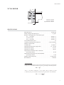
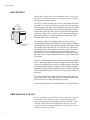
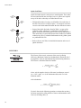
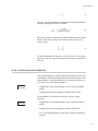
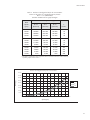
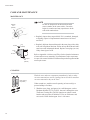
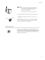
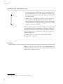
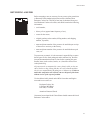
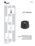
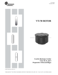
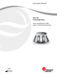
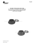
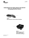
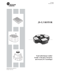
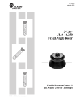
L5-TB-099E November 2007 NVT 65 Rotor Used In Beckman Coulter Class H, R, and S Preparative Ultracentrifuges © 2007 Beckman Coulter, Inc. Printed in the U.S.A. NVT 65 Rotor ! SAFETY NOTICE This safety notice summarizes information basic to the safe use of the rotor described in this manual. The international symbol displayed above is a reminder to the user that all safety instructions should be read and understood before operation or maintenance of this equipment is attempted. When you see the symbol on other pages throughout this publication, pay special attention to the specific safety information presented. Observance of safety precautions will also help to avoid actions that could damage or adversely affect the performance of the rotor. This rotor was developed, manufactured, and tested for safety and reliability as part of a Beckman Coulter ultracentrifuge/rotor system. Its safety or reliability cannot be assured if used in a centrifuge not of Beckman Coulter’s manufacture or in a Beckman Coulter ultracentrifuge that has been modified without Beckman Coulter’s approval. ! ! ! ! 2 Handle body fluids with care because they can transmit disease. No known test offers complete assurance that such fluids are free of micro-organisms. Some of the most virulent—Hepatitis (B and C) viruses, HIV (I–V), atypical mycobacteria, and certain systemic fungi—further emphasize the need for aerosol protection. Handle other infectious samples according to good laboratory procedures and methods to prevent spread of disease. Because spills may generate aerosols, observe proper safety precautions for aerosol containment. Do not run toxic, pathogenic, or radioactive materials in this rotor without taking appropriate safety precautions. Biosafe containment should be used when Risk Group II materials (as identified in the World Health Organization Laboratory Biosafety Manual) are handled; materials of a higher group require more than one level of protection. The rotor and accessories are not designed for use with materials capable of developing flammable or explosive vapors. Do not centrifuge such materials in nor handle or store them near the ultracentrifuge. Although rotor components and accessories made by other manufacturers may fit in the NVT 65 rotor, their safety in this rotor cannot be ascertained by Beckman Coulter. Use of other manufacturers’ components or accessories in the NVT 65 rotor may void the rotor warranty and should be prohibited by your laboratory safety officer. Only the components and accessories listed in this publication should be used in this rotor. Do not run an empty rotor. Place filled tubes in at least two opposing cavities. Make sure that filled containers are loaded symmetrically into the rotor and that opposing tubes are filled to the same level with liquid of the same density. Make sure that cavities in use have the proper spacers inserted before installing the rotor plugs. ! If disassembly reveals evidence of leakage, you should assume that some fluid escaped the rotor. Apply appropriate decontamination procedures to the centrifuge and accessories if pathogenic or radioactive materials are involved. ! Never exceed the maximum rated speed of the rotor and labware in use. Refer to the section on RUN SPEEDS, and derate the run speed as appropriate. ! Do not use sharp tools on the rotor that could cause scratches in the rotor surface. Corrosion begins in scratches and may open fissures in the rotor with continued use. NVT 65 Rotor NVT 65 ROTOR 7.5° rmin rav rmax U.S. Pat. No. 4,102,490 U.S. Pat. No. 4,290,550 Japanese U.M. No. 1,469,154 Axis of Rotation SPECIFICATIONS Maximum speed . . . . . . . . . . . . . . . . . . . . . . . . . . . . . . . . . . . . 65 000 rpm Density rating at maximum speed . . . . . . . . . . . . . . . . . . . . . . . . . 1.7 g/mL Relative Centrifugal Field* at maximum speed At rmax (84.9 mm) . . . . . . . . . . . . . . . . . . . . . . . . . . . . . . . 402 000 × g At rav (72.2 mm) . . . . . . . . . . . . . . . . . . . . . . . . . . . . . . . . 342 000 × g At rmin (59.5 mm). . . . . . . . . . . . . . . . . . . . . . . . . . . . . . . . 282 000 × g k factor at maximum speed . . . . . . . . . . . . . . . . . . . . . . . . . . . . . . . . . . . 21 Conditions requiring speed reductions . . . . . . . . . . . . . . . see RUN SPEEDS Number of tube cavities . . . . . . . . . . . . . . . . . . . . . . . . . . . . . . . . . . . . . . 8 Available tubes . . . . . . . . . . . . . . . . . . . . . . . . . . . . . . . . . . . . . see Table 1 Nominal tube dimensions (largest tube) . . . . . . . . . . . . . . . . . . 16 × 76 mm Nominal tube capacity. . . . . . . . . . . . . . . . . . . . . . . . . . . . . . . . . . . 13.5 mL Nominal rotor capacity . . . . . . . . . . . . . . . . . . . . . . . . . . . . . . . . . . 108 mL Approximate acceleration time to maximum speed (fully loaded) . . . . . . . . . . . . . . . . . . . . . . . . . . . . . . . . . . 10 min Approximate deceleration time from maximum speed (fully loaded) . . . . . . . . . . . . . . . . . . . . . . . . . . . . . . . . . . . 7 min Weight of fully loaded rotor . . . . . . . . . . . . . . . . . . . . . . . . . 9.8 kg (22 lb) Rotor material . . . . . . . . . . . . . . . . . . . . . . . . . . . . . . . . . . . . . . . . . titanium * Relative Centrifugal Field (RCF) is the ratio of the centrifugal acceleration at a specified radius and speed (rω 2) to the standard acceleration of gravity (g) according to the following formula: rω 2 RCF = --------g where r is the radius in millimeters, ω is the angular velocity in radians per second (2 π RPM /60), and g is the standard acceleration of gravity (9807 mm/s 2). After substitution: RPM 2 RCF = 1.12 r ------------ 1000 3 NVT 65 Rotor DESCRIPTION This Beckman Coulter rotor has been manufactured in a registered ISO 9001 or 13485 facility for use with the appropriately classified Beckman Coulter ultracentrifuge. Plug (392083) Plug Gasket (349220) Overspeed Disk (330338) The NVT 65, rated for 65 000 rpm, is a near-vertical tube rotor with a tube angle of 7.5 degrees to the axis of rotation. The rotor can centrifuge up to eight tubes and is used in Beckman Coulter Class H, R, and S preparative ultracentrifuges. The slight angle of this rotor significantly reduces run times from a more conventional fixed angle rotor (with a tube angle of 20 to 30 degrees), while allowing components that do not band under separation conditions to either pellet to the bottom or float to the top of the tube. One example of this type of sample is the separation of closed circular plasmid DNA and linear DNA in cesium chloride-ethidium bromide gradients. RNA will pellet; protein and other cellular components with low buoyant density in CsCl will float. The supercoiled plasmid will band in the central area of the tube with CsCl densities typical for this type of separation (homogeneous starting density approximately 1.55 g/mL). With typical sample loading, the plasmid band will not be in contact with the pelleted or floated components of the gradient. The rotor is made of titanium and is finished with black polyurethane paint. A tube spacer and hex-cavity rotor plug hold each tube in the rotor, and a plug gasket forms a closure around each plug. Rotor plugs are red-anodized aluminum, and spacers are blue-anodized (QuickSeal® tubes) or gold-anodized (OptiSeal™ tubes) aluminum. Because of the weight of the rotor, drive pins are not required in the rotor drive hub cavity. For overspeed protection, a photoelectric detector in the ultracentrifuge monitors the overspeed disk on the rotor bottom and shuts down the run if speeds exceeding 65 000 rpm are detected. See the Warranty at the back of this manual for warranty information. PREPARATION AND USE Specific information about the NVT 65 rotor is given here. Information common to this and other rotors is contained in Rotors and Tubes for Preparative Ultracentrifuges (publication LR-IM), which should be used together with this manual for complete rotor and accessory operation. Publication LR-IM is included in the literature package with this rotor manual. 4 NVT 65 Rotor ➠ NOTE Although rotor components and accessories made by other manufacturers may fit in the NVT 65 rotor, their safety in this rotor cannot be ascertained by Beckman Coulter. Use of other manufacturers’ components or accessories in the NVT 65 rotor may void the rotor warranty and should be prohibited by your laboratory safety officer. Only the components and accessories listed in this publication should be used in this rotor. PRERUN SAFETY CHECKS ! Read the Safety Notice page at the front of this manual before using the rotor. 1. Inspect the rotor plugs and gaskets for damage—the high forces generated in this rotor can cause damaged components to fail. 65 000-rpm 28-Sector (330338) 2. Make sure that the rotor is equipped with the correct overspeed disk (330338). If the disk is missing or damaged, replace it according to the instructions in Rotors and Tubes. 3. Verify that only the tubes and accessories listed in Table 1 are being used. Check the chemical compatibilities of all materials used (refer to Appendix A in Rotors and Tubes). ROTOR PREPARATION For runs at other than room temperature, refrigerate or warm the rotor beforehand for fast equilibration. 1. Be sure that the plug threads are clean and lightly but evenly lubricated with Spinkote™ lubricant (306812) to ensure a proper seal by minimizing thread friction. 2. Set the rotor in the rotor vise (342705), which should be bolted or clamped to a rigid surface (see Figure 1). 5 NVT 65 Rotor Torque Wrench (858121) T40 Torx Adapter (976959) Rotor Vise Assembly (342705) Plug Gasket (349290) Rotor Plug (392083) Figure 1. The NVT 65 Rotor and Rotor Vise Assembly 3. Load the filled and sealed tubes symmetrically into the rotor (see page 8 for tube information). If fewer than eight tubes are being run, they must be arranged symmetrically in the rotor (see Figure 2). Opposing tubes must be filled to the same level with liquid of the same density. Figure 2. Arranging Tubes in the Rotor. Two, four, six, or eight tubes can be centrifuged per run if they are arranged in the rotor as shown. 6 NVT 65 Rotor 4. Complete loading by placing the correct spacers (and floating spacers, if applicable) over the tubes. It is important that each cavity being used is completely filled. 5. Insert a rotor plug (392083), gasket-end down, over each spacer and screw it in. ➠ NOTE Do not use rotor plugs in empty cavities. 6. Using the T40 Torx adapter (976959) and torque wrench (858121), tighten each rotor plug to 13.6 N•m (120 in.-lb). To avoid stripping the plugs, apply downward pressure to the plug adapter while tightening the plugs. Do not overtighten plugs; the top surface of each rotor plug should be flush with the surrounding rotor surface. OPERATION Lower the rotor straight down onto the drive hub. 1. Carefully place the rotor on the drive hub. 2. Refer to the instrument instruction manual for ultracentrifuge operation. 3. For additional operating information, see the following: • RUN TIMES, page 10, for using k factors to adjust run durations. • RUN SPEEDS, page 12, for information about speed limitations. • SLOW ACCELERATION/DECELERATION, page 11, for information about using slow acceleration and deceleration for gradient stability. • SELECTING CsCl GRADIENTS, page 12, for methods to avoid CsCl precipitation during centrifugation. 7 NVT 65 Rotor REMOVAL AND SAMPLE RECOVERY ! CAUTION If disassembly reveals evidence of leakage, you should assume that some fluid escaped the rotor. Apply appropriate decontamination procedures to the centrifuge and accessories. 1. Remove the rotor from the centrifuge by lifting it straight up and off the drive hub. 2. Return the rotor to the rotor vise. Remove the plugs with the torque wrench and T40 Torx adapter. To avoid stripping the plugs, apply downward pressure to the plug adapter while loosening the plugs. Quick-Seal Tube Removal Tool (361668) 3. Use the appropriate removal tool (see the SUPPLY LIST) to remove the spacers and tubes. TUBES The NVT 65 rotor uses only OptiSeal™ and Quick-Seal® tubes; use only the tubes and accessories listed in Table 1. Refer to Rotors and Tubes for information on the chemical resistances of tube and accessory materials. OptiSeal and Quick-Seal tubes are disposable and should be discarded after a single use. Temperature Limits 25°C 2°C 8 • Plastic tubes have been centrifuge tested for use at temperatures between 2 and 25°C. For centrifugation at other temperatures, pretest tubes under anticipated run conditions. • If tubes are frozen before use, make sure that they are thawed to at least 2°C prior to centrifugation. NVT 65 Rotor Table 1. Available Tubes for the NVT 65 Rotor. Use only the items listed here. Tube Dimensions and Volume Required Accessory Description Part Number Description 16 × 76 mm 13.5 mL Quick-Seal Ultra-Clear 344322 (pkg/50) 16 × 76 mm 13.5 mL Quick-Seal polyallomer 16 × 70 mm 11.2 mL 16 × 67 mm 10 mL 16 × 58 mm 8 mL 16 × 44 mm 6.3 mL Max Speed/ RCF/ k Factor Part Number Tube Rack blue-anodized aluminum spacer 349289 348123 65 000 rpm 402 000 × g 21 342413 (pkg/50) blue-anodized aluminum spacer 349289 348123 65 000 rpm 402 000 × g 21 OptiSeal polyallomer 362181* (pkg/56) gold-anodized aluminum spacer 362202 360538 65 000 rpm 402 000 × g 17 Quick-Seal polyallomer 344622 (pkg/50) blue-anodized aluminum spacer 349289 348123 65 000 rpm 402 000 × g 15 floating spacer † 349901 blue-anodized aluminum spacer 349289 348123 65 000 rpm 402 000 × g 11 floating spacer 356571 blue-anodized aluminum spacer 349289 348123 65 000 rpm 402 000 × g 8 floating spacer 349900 Quick-Seal polyallomer Quick-Seal polyallomer 344621 (pkg/50) 345830 (pkg/50) * Includes disposable plastic plugs. † Floating spacers, part of the g-Max system of tube support, are made of Noryl, a registered trademark of GE Plastics. OptiSeal™ Tubes Gold Aluminum Spacer Plug OptiSeal tubes come with plastic plugs and can be quickly and easily prepared for use without tools or heat. With the tube spacer and rotor plug in place, the combination of g force and hydrostatic pressure during centrifugation ensures a tight, reliable seal that protects your samples. Fill each tube to the base of the stem, leaving no fluid in the stem. Overfilling the tube can cause spillage when the plug is inserted or compromise seal integrity; however, too much air can cause the tube to deform, disrupting gradients and sample bands. Refer to publication IN-189 (Using OptiSeal™ Tubes), included in each package of OptiSeal tubes, for detailed information on the use and care of OptiSeal tubes. 9 NVT 65 Rotor Quick-Seal Tubes Quick-Seal tubes must be sealed prior to centrifugation. These tubes are heat sealed and do not need caps; however, spacers are required on top of the tubes when they are loaded into the rotor. Blue Anodized Spacer Domeshaped Tube Blue Anodized Spacer Floating Spacer Bell-top Tube • Fill Quick-Seal tubes leaving a small bubble of air at the base of the neck. Do not leave a large air space — too much air can cause excessive tube deformation and make the tube difficult to remove. • Some of the Quick-Seal tubes listed in Table 1 are part of the g-Max™ system, which uses a combination of small bell-top Quick-Seal tubes and floating spacers (also called g-Max spacers). This means that you can run the shorter tubes in this rotor without reduction in g force. For detailed information on the g-Max system see publication DS-709. • Refer to Rotors and Tubes for detailed information on the use of Quick-Seal tubes. RUN TIMES The k factor of the rotor is a measure of the rotor’s pelleting efficiency. (Beckman Coulter has calculated the k factors for all of its preparative rotors at maximum rated speed and using full tubes.) The k factor is calculated from the formula: ln ( rmax ⁄ rmin ) 10 13 k = ------------------------------------- × -----------3600 ω2 (1) where ω is the angular velocity of the rotor in radians per second (ω = 0.105 × rpm), rmax is the maximum radius, and rmin is the minimum radius. After substitution: (2.533 × 10 11) ln ( rmax ⁄ rmin ) k = ------------------------------------------------------------------------rpm 2 (2) Use the k factor in the following equation to estimate the run time t (in hours) required to pellet particles of known sedimentation coefficient s (in Svedberg units, S). 10 NVT 65 Rotor k t = -s (3) Run times can be estimated for centrifugation at less than maximum speed by adjusting the k factor as follows: 65 000 k adj = k ⎛--------------------------------------- ⎞ ⎝actual run speed ⎠ 2 (4) Run times can also be estimated from data established in prior experiments if the k factor of the previous rotor is known. For any two rotors, a and b: ka ta ----= -----tb kb (5) For more information on k factors see Use of k Factor for Estimating Run Times from Previously Established Run Conditions (publication DS-719). SLOW ACCELERATION/DECELERATION Near-vertical banding of sample and gradient formation occurs with centrifugation. With deceleration, tube contents reorient back to horizontal position. For gradient stability when preformed gradients are used, select slow acceleration as follows: ACCEL PROFILES • in Optima XL series ultracentrifuges, select a slow acceleration profile. • in Optima L series ultracentrifuges, select SLOW ACCEL. For the stability of all gradients during deceleration, do the following: DECEL PROFILES • in Optima XL series ultracentrifuges, select a slow deceleration profile. • in Optima L series ultracentrifuges, select SLOW DECEL. • in L7 series ultracentrifuges, set the brake switch in the 800 rpm position. 11 NVT 65 Rotor RUN SPEEDS SPEED RPM/RCF 65 000 RPM The centrifugal force at a given radius in a rotor is a function of speed. Comparisons of forces between different rotors are made by comparing the rotors’ relative centrifugal fields (RCF). When rotational speed is adjusted so that identical samples are subjected to the same RCF in two different rotors, the samples are subjected to the same force. The RCF at a number of rotor speeds is provided in Table 2. Speeds must be reduced under the following circumstances: 1. If nonprecipitating solutions more dense than 1.7 g/mL are centrifuged, the maximum allowable run speed must be reduced according to the following equation: reduced maximum speed = (65 000 rpm) 1.7 g/mL ---------------------ρ (6) where ρ is the density of the tube contents. This speed reduction will protect the rotor from excessive stresses due to the added tube load. Note, however, that the use of this formula may still produce maximum speed figures that are higher than the limitations imposed by the use of certain tubes or adapters. In such cases, use the lower of the two figures. 2. Further speed limits must be imposed when CsCl or other selfforming-gradient salts are centrifuged, as equation (6) does not predict concentration limits/speeds that are required to avoid precipitation of salt crystals. Precipitation during centrifugation would alter the density distribution of CsCl and this would change the position of the sample bands. Figures 3 and 4, together with the description and examples below, show how to reduce run speeds when using CsCl gradients. SELECTING CsCl GRADIENTS Precipitation during centrifugation would alter density distribution, and this would change the position of the sample bands. Curves in Figures 3 and 4 are provided up to the maximum rated speed of the rotor. 12 NVT 65 Rotor Table 2. Relative Centrifugal Fields for the NVT 65 Rotor. Entries in this table are calculated from the formula RCF = 1.12r (RPM/1000)2 and then rounded to three significant digits. Relative Centrifugal Field (x g) Rotor Speed (rpm) At rmax (84.9 mm) At rav (72.2 mm) At rmin (59.5 mm) k Factor* 65 000 60 000 55 000 50 000 402 000 342 000 288 000 238 000 342 000 291 000 245 000 202 000 282 000 240 000 202 000 167 000 21 25 30 36 45 000 40 000 35 000 30 000 193 000 152 000 117 000 85 600 164 000 129 000 99 100 72 800 135 000 107 000 81 600 60 000 44 56 74 100 25 000 20 000 15 000 10 000 59 400 38 000 21 400 9 510 50 500 32 400 18 200 2 020 41 700 26 700 15 000 1 670 144 225 400 900 *Calculated for all Beckman Coulter preparative rotors as a measure of the rotor’s relative efficiency in pelleting sample in water at 20°C. Relative Centrifugal Fields for the NVT 65 Rotor 450 000 400 000 RCF (x g) 350 000 300 000 rmax 250 000 rav rmin 200 000 150 000 100 000 50 000 0 0 5 000 10 000 15 000 20 000 25 000 30 000 35 000 40 000 45 000 50 000 55 000 60 000 65 000 Speed (rpm) 13 NVT 65 Rotor 1.9 1.8 Homogeneous CsCl Solution (g/mL) 1.7 1.6 1.5 1.4 NVT 65 ROTOR = 20°C 1.3 = 4°C 1.2 1.1 0 10 20 30 40 50 60 Rotor Speed (K rpm) Figure 3. Precipitation Curves for the NVT 65 Rotor. Using combinations of rotor speeds and homogeneous CsCl solution densities that intersect on or below these curves ensures that CsCl will not precipitate during centrifugation. 14 65 NVT 65 Rotor 1.9 1.8 1.7 Homogeneous CsCl Solution (g/mL) 45 000 rpm 50 1.6 000 rpm pm 0r 0 50 pm 5 m 6 0 rp 0 45 0 0r 0 00 m 0 65 00 rp 1.5 50 1.4 55 000 000 rpm rpm pm 0r 0 00 6 1.3 00 0 65 rpm NVT 65 ROTOR = 20°C 1.2 = 4°C 1.1 1.0 59.5 rmin 62.7 65.9 68.9 72.2 75.4 78.6 81.8 Distance from Axis of Rotation (mm) 84.9 rmax Figure 4. CsCl Gradients at Equilibrium for the NVT 65 Rotor. Centrifugation of homogeneous CsCl solutions at the maximum allowable speeds (from Figure 3) results in gradients presented here. 15 NVT 65 Rotor ➠ NOTE The curves in Figures 3 and 4 are for solutions of CsCl salt dissolved in distilled water only. If other salts are present in significant concentrations, the overall CsCl concentration may need to be reduced. Rotor speed is used to control the slope of a CsCl density gradient, and must be limited so that CsCl precipitation is avoided. Speed and density combinations that intersect on or below the curves in Figure 4 ensure that CsCl will not precipitate during centrifugation in the NVT 65 rotor. Curves are provided at two temperatures: 20˚C (black curves) and 4°C (gray curves). The reference curves in Figure 4 show gradient distribution at equilibrium. Each curve in Figure 4 is within the density limits allowed for the NVT 65 rotor: each curve was generated for a single run speed using the maximum allowable homogeneous CsCl densities (one for each fill level) that avoid precipitation at that speed. (The gradients in Figure 4 can be generated from step or linear gradients, or from homogeneous solutions. But the total amount of CsCl in solution must be equivalent to a homogeneous solution corresponding to the concentrations specified in Figure 4.) Figure 4 can also be used to approximate the banding positions of sample particles. TYPICAL EXAMPLES FOR DETERMINING CsCl RUN PARAMETERS Example A: A separation that is done frequently is the banding of plasmid DNA in cesium chloride with ethidium bromide. The starting density of the CsCl solution is 1.55 g/mL. In this separation the covalently closed, circular plasmid bands at a density of 1.57 g/mL, while the nicked and linear species band at 1.53 g/mL. At 20°C, where will particles band? 1. In Figure 3, find the curve that corresponds to the required run temperature (20°C). The maximum allowable rotor speed is determined from the point where this curve intersects the homogeneous CsCl density (62 000 rpm). 16 NVT 65 Rotor At Speed Floating Components 2. In Figure 4, sketch in a horizontal line corresponding to each particle’s buoyant density. 3. Mark the point in the figure where each particle density intersects the curve corresponding to the selected run speed and temperature. Bands 4. Particles will band at these locations across the tube diameter at equilibrium during centrifugation. Pelleted Material At Rest in Rotor In this example, particles will band about 71.3 and 73.1 mm from the axis of rotation, about 1.8 mm of centerband-to-centerband separation at the rotor’s 7.5-degree tube angle. When the tube is held upright, there will be about 1.82 mm of centerband-to-centerband separation. This interband distance, dup, can be calculated from the formula: dθ d up = ----------cos θ (7) Upright where dθ is the interband distance when the tube is held at an angle, θ, in the rotor. Example B: Knowing particle buoyant densities (e.g., 1.64 and 1.67 g/mL), how do you achieve good separation? 1. In Figure 4, sketch in a horizontal line corresponding to each particle’s buoyant density. 2. Select the curve at the temperature (20°C) that gives the best particle separation. 3. Note the run speed along the selected curve. 4. From Figure 3, select the maximum homogeneous CsCl density that corresponds to the temperature and run speed established above. These parameters will provide the particle-banding pattern selected in Step 2. 17 NVT 65 Rotor CARE AND MAINTENANCE MAINTENANCE ➠ Centering Tool (331325) NOTE Do not use sharp tools on the rotor that could cause scratches in the rotor surface. Corrosion begins in scratches and may open fissures in the rotor with continued use. • Regularly inspect the overspeed disk. If it is scratched, damaged, or missing, replace it. Replacement instructions are in Rotors and Tubes. Threads Plug (392083) Check for Corrosion Overspeed Disk (330338) • Regularly lubricate the metal threads in the rotor plugs with a thin, even coat of Spinkote lubricant. Failure to keep these threads lubricated can result in damaged threads. Replace rotor plugs (as a set) if they show signs of wear. Refer to Appendix A in Rotors and Tubes for the chemical resistances of rotor and accessory materials. Your Beckman Coulter representative provides contact with the Field Rotor Inspection Program and the rotor repair center. CLEANING Rotor Cleaning Kit (339558) Wash the rotor and rotor components immediately if salts or other corrosive materials are used or if spillage has occurred. Do not allow corrosive materials to dry on the rotor. Under normal use, wash the rotor frequently (at least weekly) to prevent buildup of residues. 1. Wash the rotor, plugs, and spacers in a mild detergent, such as Beckman Solution 555™ (339555), that won’t damage the rotor. The Rotor Cleaning Kit (339558) contains two plastic-coated brushes and two quarts of Solution 555 for use with rotors and accessories. Dilute the detergent 10 to 1 with water. 18 NVT 65 Rotor ➠ NOTE Do not wash rotor components in a dishwasher. Do not soak in detergent solution for long periods, such as overnight. 2. Rinse the cleaned rotor and components with distilled water. Gasket 3. Air-dry the rotor upside down. Do not use acetone to dry the rotor. Threads Clean plug threads as necessary. Use a brush and concentrated Solution 555. Rinse and dry thoroughly, then lubricate lightly but evenly with Spinkote to coat all threads. DECONTAMINATION If the rotor or other components are contaminated with toxic or pathogenic materials, follow appropriate decontamination procedures as outlined by your laboratory safety officer. Check Appendix A in Rotors and Tubes to be sure the decontamination method will not damage any part of the rotor. 19 NVT 65 Rotor STERILIZATION AND DISINFECTION 121°C • The rotor and all rotor components, except those made of Noryl, can be autoclaved at 121°C for up to an hour. Remove the plugs from the rotor and place the rotor, plugs, and spacers in the autoclave upside down. * • Ethanol (70%) or hydrogen peroxide (6%) may be used on all rotor components, including those made of plastic. Bleach (sodium hypochlorite) may be used, but may cause discoloration of anodized surfaces. Use the minimum immersion time for each solution, per laboratory standards. While Beckman Coulter has tested these methods and found that they do not damage the rotor or components, no guarantee of sterility or disinfection is expressed or implied. When sterilization or disinfection is a concern, consult your laboratory safety officer regarding proper methods to use. OptiSeal and Quick-Seal tubes are disposable and should be discarded after a single use. STORAGE When it is not in use, store the rotor in a dry environment (not in the instrument) with plugs removed to allow air circulation so moisture will not collect in the tube cavities. * 20 Flammability hazard. Do not use in or near operating ultracentrifuges. NVT 65 Rotor RETURNING A ROTOR RGA Before returning a rotor or accessory for any reason, prior permission (a Returned Goods Authorization form) must be obtained from Beckman Coulter, Inc. This RGA form may be obtained from your local Beckman Coulter sales office, and should contain the following information: • serial number, • history of use (approximate frequency of use), • reason for the return, • original purchase order number, billing number, and shipping number, if possible, • name and phone number of the person to be notified upon receipt of the rotor or accessory at the factory, • name and phone number of the person to be notified about repair costs, etc. To protect our personnel, it is the customer's responsibility to ensure that all parts are free from pathogens and/or radioactivity. Sterilization and decontamination must be done before returning the parts. Smaller items (such as tubes, bottles, etc.) should be enclosed in a sealed plastic bag. All parts must be accompanied by a note, plainly visible on the outside of the box or bag, stating that they are safe to handle and that they are not contaminated with pathogens or radioactivity. Failure to attach this notification will result in return or disposal of the items without review of the reported problem. Use the address label printed on the RGA form when mailing the rotor and/or accessories to: Beckman Coulter, Inc. 1050 Page Mill Road Palo Alto, CA 94304 Attention: Returned Goods Customers located outside the United States should contact their local Beckman Coulter office. 21 NVT 65 Rotor SUPPLY LIST ➠ NOTE Publications referenced in this manual can be obtained by calling Beckman Coulter at 1-800742-2345 in the United States, or by contacting your local Beckman Coulter office. Call Beckman Coulter Sales (1-800-742-2345 in the United States; worldwide offices are listed on the back cover of this manual) or see the Beckman Coulter Ultracentrifuge Rotors, Tubes & Accessories catalog (BR-8101) for detailed information on ordering parts and supplies. For your convenience, a partial list is given below. REPLACEMENT ROTOR PARTS NVT 65 rotor assembly . . . . . . . . . . . . . . . . . . . . . . . . . . . . . . . . . . . Rotor plug . . . . . . . . . . . . . . . . . . . . . . . . . . . . . . . . . . . . . . . . . . . . . Rotor plug gasket . . . . . . . . . . . . . . . . . . . . . . . . . . . . . . . . . . . . . . . Overspeed disk (65 000 rpm) . . . . . . . . . . . . . . . . . . . . . . . . . . . . . . Rotor vise assembly . . . . . . . . . . . . . . . . . . . . . . . . . . . . . . . . . . . . . 362755 392083 349290 330338 342705 OTHER Tubes and accessories . . . . . . . . . . . . . . . . . . . . . . . . . . . . . . . . . see Table 1 Quick-Seal Cordless Tube Topper kit, 60 Hz . . . . . . . . . . . . . . . . . . 358312 Quick-Seal Cordless Tube Topper kit, 50 Hz (Europe) . . . . . . . . . . 358313 Quick-Seal Cordless Tube Topper kit, 50 Hz (Great Britain) . . . . . . 358314 Quick-Seal Cordless Tube Topper kit, 50 Hz (Australia) . . . . . . . . . 358315 Quick-Seal Cordless Tube Topper kit, 50 Hz (Canada) . . . . . . . . . . 367803 Tube Topper rack (16-mm dia. tubes) . . . . . . . . . . . . . . . . . . . . . . . . 348123 Torque wrench. . . . . . . . . . . . . . . . . . . . . . . . . . . . . . . . . . . . . . . . . . 858121 T40 Torx plug adapter . . . . . . . . . . . . . . . . . . . . . . . . . . . . . . . . . . . . 976959 Tube removal tool . . . . . . . . . . . . . . . . . . . . . . . . . . . . . . . . . . . . . . . 361668 Floating spacer removal tool . . . . . . . . . . . . . . . . . . . . . . . . . . . . . . . 338765 Spinkote lubricant (1 oz) . . . . . . . . . . . . . . . . . . . . . . . . . . . . . . . . . . 306812 Silicone vacuum grease (2 oz) . . . . . . . . . . . . . . . . . . . . . . . . . . . . . 335148 Rotor Cleaning Kit . . . . . . . . . . . . . . . . . . . . . . . . . . . . . . . . . . . . . . 339558 Beckman Solution 555 (1 qt) . . . . . . . . . . . . . . . . . . . . . . . . . . . . . . 339555 Rotor cleaning brush . . . . . . . . . . . . . . . . . . . . . . . . . . . . . . . . . . . . . 339379 22 ULTRACENTRIFUGE ROTOR WARRANTY All Beckman Coulter ultracentrifuge Fixed Angle, Vertical Tube, Near Vertical Tube, Swinging Bucket, and Airfuge rotors are warranted against defects in materials or workmanship for the time periods indicated below, subject to the Warranty Conditions stated below. Preparative Ultracentrifuge Rotors . . . . . 5 years — No Proration Analytical Ultracentrifuge Rotors. . . . . . 5 years — No Proration ML and TL Series Ultracentrifuge Rotors . . . . . . . . . . . . . . . . . . . . . . . . . 5 years — No Proration Airfuge Ultracentrifuge Rotors . . . . . . . . . 1 year — No Proration For Zonal, Continuous Flow, Component Test, and Rock Core ultracentrifuge rotors, see separate warranty. Warranty Conditions (as applicable) 1) This warranty is valid for the time periods indicated above from the date of shipment to the original Buyer by Beckman Coulter or an authorized Beckman Coulter representative. 2) This warranty extends only to the original Buyer and may not be assigned or extended to a third person without written consent of Beckman Coulter. 3) This warranty covers the Beckman Coulter Centrifuge Systems only (including but not limited to the centrifuge, rotor, and accessories) and Beckman Coulter shall not be liable for damage to or loss of the user’s sample, non-Beckman Coulter tubes, adapters, or other rotor contents. 4) This warranty is void if the Beckman Coulter Centrifuge System is determined by Beckman Coulter to have been operated or maintained in a manner contrary to the instructions in the operator’s manual(s) for the Beckman Coulter Centrifuge System components in use. This includes but is not limited to operator misuse, abuse, or negligence regarding indicated maintenance procedures, centrifuge and rotor classification requirements, proper speed reduction for the high density of certain fluids, tubes, and tube caps, speed reduction for precipitating gradient materials, and speed reduction for high-temperature operation. 5) Rotor bucket sets purchased concurrently with or subsequent to the purchase of a Swinging Bucket Rotor are warranted only for a term co-extensive with that of the rotor for which the bucket sets are purchased. 6) This warranty does not cover the failure of a Beckman Coulter rotor in a centrifuge not of Beckman Coulter manufacture, or if the rotor is used in a Beckman Coulter centrifuge that has been modified without the written permission of Beckman Coulter, or is used with carriers, buckets, belts, or other devices not of Beckman Coulter manufacture. 7) Rotor parts subject to wear, including but not limited to rotor O-rings, VTi, NVT™, TLV, MLN, and TLN rotor tube cavity plugs and gaskets, tubing, tools, optical overspeed disks, bearings, seals, and lubrication are excluded from this warranty and should be frequently inspected and replaced if they become worn or damaged. 8) Keeping a rotor log is not mandatory, but may be desirable for maintenance of good laboratory practices. Repair and Replacement Policies 1) If a Beckman Coulter rotor is determined by Beckman Coulter to be defective, Beckman Coulter will repair or replace it, subject to the Warranty Conditions. A replacement rotor will be warranted for the time remaining on the original rotor’s warranty. 2) If a Beckman Coulter centrifuge is damaged due to a failure of a rotor covered by this warranty, Beckman Coulter will supply free of charge (i) all centrifuge parts required for repair (except the drive unit, which will be replaced at the then current price less a credit determined by the total number of revolutions or years completed, provided that such a unit was manufactured or rebuilt by Beckman Coulter), and (ii) if the centrifuge is currently covered by a Beckman Coulter warranty or Full Service Agreement, all labor necessary for repair of the centrifuge. 3) If a Beckman Coulter rotor covered by this warranty is damaged due to a malfunction of a Beckman Coulter ultracentrifuge covered by an Ultracentrifuge System Service Agreement, Beckman Coulter will repair or replace the rotor free of charge. 4) If a Beckman Coulter rotor covered by this warranty is damaged due to a failure of a Beckman Coulter tube, bottle, tube cap, spacer, or adapter, covered under the Conditions of this Warranty, Beckman Coulter will repair or replace the rotor and repair the instrument as per the conditions in policy point (2) above, and the replacement policy. 5) Damage to a Beckman Coulter rotor or instrument due to the failure or malfunction of a non-Beckman Coulter tube, bottle, tube cap, spacer, or adapter is not covered under this warranty, although Beckman Coulter will assist in seeking compensation under the manufacturer’s warranty. Disclaimer IT IS EXPRESSLY AGREED THAT THE ABOVE WARRANTY SHALL BE IN LIEU OF ALL WARRANTIES OF FITNESS AND OF THE WARRANTY OF MERCHANTABILITY AND BECKMAN COULTER, INC. SHALL HAVE NO LIABILITY FOR SPECIAL OR CONSEQUENTIAL DAMAGES OF ANY KIND WHATSOEVER ARISING OUT OF THE MANUFACTURE, USE, SALE, HANDLING, REPAIR, MAINTENANCE, OR REPLACEMENT OF THE PRODUCT. Factory Rotor Inspection Service Beckman Coulter, Inc., will provide free mechanical and metallurgical inspection in Palo Alto, California, USA, of any Beckman Coulter rotor at the request of the user. (Shipping charges to Beckman Coulter are the responsibility of the user.) Rotors will be inspected in the user’s laboratory if the centrifuge in which they are used is covered by an appropriate Beckman Coulter Service Agreement. Contact your local Beckman Coulter office for details of service coverage or cost. Before shipping, contact the nearest Beckman Coulter Sales and Service office and request a Returned Goods Authorization (RGA) form and packaging instructions. Please include the complete rotor assembly, with buckets, lid, handle, tube cavity caps, etc. A SIGNED STATEMENT THAT THE ROTOR AND ACCESSORIES ARE NON-RADIOACTIVE, NON-PATHOGENIC, NONTOXIC, AND OTHERWISE SAFE TO SHIP AND HANDLE IS REQUIRED. Beckman Coulter Worldwide Biomedical Research Division Offices AUSTRALIA Beckman Coulter Australia Pty Ltd Unit D, 24 College St. Gladesville, NSW 2111 Australia Telephone: (61) 2 9844-6000 or toll free: 1 800 060 880 Fax: (61) 2 9844-6096 email: [email protected] CANADA Beckman Coulter (Canada) Inc. 6755 Mississauga Road, Suite 600 Mississauga, Ontario Canada L5N 7Y2 Telephone: (1) 905 819-1234 Fax: (1) 905 819-1485 CHINA Beckman Coulter Inc. Beijing Representative Office Unit 2005A, 2006-2009, East Ocean Center Jian Guomenwai Avenue Beijing 100004 China Telephone: (86) 10 6515 6028 Fax: (86) 10 6515 6025, 6515 6026 CZECH REPUBLIC Beckman Coulter Prague Radiova 1 102 27 Prague 10 Czech Republice Telephone: (420) 267 00 85 13 Fax: (420) 267 00 83 23 EASTERN EUROPE/ MIDDLE EAST/NORTH AFRICA Beckman Coulter International S.A. 22, Rue Juste-Olivier Case Postale 301-303 CH-1260 Nyon, Switzerland Telephone: (41) 22 365 3707 Fax: (41) 22 365 0700 FRANCE Beckman Coulter France S.A. Paris Nord II, 33/66 rue des Vanesses B.P. 50359 Villepinte, France 95942 ROISSY CDG Cedex Telephone: (33) 1 49 90 90 00 Fax: (33) 1 49 90 90 10 e-mail: [email protected] GERMANY Beckman Coulter GmbH Europark Fichtenhain B-13 47807 Krefeld Germany Telephone: (49) 21 51 33 35 Fax: (49) 21 51 33 33 e-mail: [email protected] HONG KONG Beckman Coulter Hong Kong Ltd. 12th Floor, Oxford House 979 King’s Road Taikoo Place, Hong Kong Telephone: (852) 2814 7431 Fax: (852) 2873 4511 SPAIN Beckman Coulter España S.A. C/ Caleruega, 81 28033 Madrid, Spain Telephone: (34) 91 3836080 Fax: (34) 91 3836096 email: [email protected] INDIA Beckman Coulter India Pvt. Ltd. Solitaire Corporate Park 3rd Floor - Bldg. 11 Andheri Ghatkopar Link Road Chakala, Andheri West Mumbai India 400 098 Telephone: (91) 22 3080 5101 SWEDEN Beckman Coulter AB Archimedesvaegen 7 Box 111 56 SE-168 11 Bromma Sweden Telephone: (46) 8 564 85 900 Telefax: (46) 8 564 85 901 ITALY Beckman Coulter S.p.a. Centro Direzionale Lombardo Palazzo F/1, Via Roma 108 20060 Cassina de’ Pecchi Milano, Italy Telephone: (39) 02 953921 Fax: (39) 02 95392264 JAPAN Beckman Coulter K.K. TOC Ariake West Tower 2-5-7, Ariake, Koto-ku Tokyo 135-0063 Japan Telephone: (81) 3 5530 8500 Fax: (81) 3 5404 8436 MEXICO Beckman Coulter de Mexico S.A. de C.V. Avenida Popocatépetl #396 Colonia Gral. Pedro Maria Anaya Codigo Postal 03340 Mexico, D.F. Mexico Telephone: (001) 52-55-9183-2800 NETHERLANDS Beckman Coulter Nederland B.V. Nijverheidsweg 21 3641 RP-Mijdrecht Postbus 47 3640 AA Mijdrecht The Netherlands Telephone: (31) 297-230630 Fax: (31) 297-288082 SINGAPORE Beckman Coulter Singapore Pte. Ltd. 116 Changi Road Unit #03-01/02 Singapore 419718 Telephone: (65) 6339 3633 Fax: (65) 6336 6303 SOUTH AFRICA/SUB-SAHARAN AFRICA Beckman Coulter Stand 1A Primegro Park Tonetti Street 1685 Halfway House Johannesburg Republic of South Africa Telephone: (27) 11-805-2014/5 Fax: (27) 11-805-4120 e-mail: [email protected] SWITZERLAND Beckman Coulter International S.A. 22, Rue Juste-Olivier Case Postale 301-303 CH-1260 Nyon Switzerland Telephone: (41) 0800 850 810 Fax: (41) 0848 850 810 TAIWAN Beckman Coulter Taiwan Inc. Taiwan Branch 8th Floor 216 Tun Hwa South Road, Section 2 Taipei 106, Taiwan Republic of China Telephone: (886) 2 2378 3456 Fax: (886) 2 2377 0408 TURKEY Beckman Coulter Ltd. E-5 Yanyol Faith Cad. 81410 Soganlik Kartal Istanbul Turkey Telephone: (90) 216 309 1900 Fax: (90) 216 309 0090 UNITED KINGDOM Beckman Coulter United Kingdom Ltd Oakley Court Kingsmead Business Park London Road High Wycombe Buckinghamshire HP11 1JU England, U.K. Telephone: (44) 01494 441181 Fax: (44) 01494 447558 e-mail: [email protected] Additional addresses are available at www.beckmancoulter.com. Beckman Coulter, Inc. • 4300 N. Harbor Boulevard, Box 3100 • Fullerton, California 92834-3100 Sales and Service: 1-800-742-2345 • Internet: www.beckmancoulter.com • Telex: 678413 • Fax: 1-800-643-4366 ©2007 Beckman Coulter, Inc. Printed on recycled paper