1
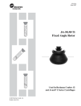
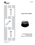
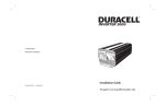
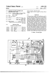
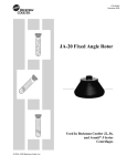
J6-TB-006K
December 2007
Instructions for Using JS-5.2 and JS-4.0
Swinging Bucket Rotors
JS-5.2
Used in Beckman Coulter J6 Series Centrifuges
JS-4.0
Used in Beckman Coulter
Avanti® J-26XP Series
and J6 Series Centrifuges
© 2007 Beckman Coulter, Inc.
Printed in the U.S.A.
JS-5.2 and JS-4.0 Rotors
!
SAFETY NOTICE
This safety notice summarizes information basic to the safe use of the equipment described in this publication. The
international symbol displayed above is a reminder to the user that all safety instructions should be read and understood before operation or maintenance of this equipment is attempted. When you see the symbol on other pages of
this publication, pay special attention to the specific safety information presented. Observance of safety precautions
will also help to avoid actions that could damage or adversely affect the performance of the rotor system. This rotor
was developed, manufactured, and tested for safety and reliability as part of a Beckman Coulter centrifuge/rotor
system. Its safety or reliability cannot be assured if used in a centrifuge not of Beckman Coulter’s manufacture or
in a Beckman Coulter centrifuge that has been modified without Beckman Coulter’s approval.
!
!
Dispose of all waste solutions according to appropriate environmental health and safety guidelines.
!
The rotors and accessories are not designed for use with materials capable of developing flammable or
explosive vapors. Do not centrifuge such materials (such as chloroform or ethyl alcohol) in or handle
or store them near the centrifuge.
!
2
Handle body fluids with care because they can transmit disease. No known test offers complete assurance that such fluids are free of micro-organisms. Some of the most virulent—Hepatitis (B and C)
viruses, HIV (I–V), atypical mycobacteria, and certain systemic fungi—further emphasize the need
for aerosol protection. Handle other infectious samples according to good laboratory procedures and
methods to prevent spread of disease. Because spills may generate aerosols, observe proper safety
precautions for aerosol containment. Do not run toxic, pathogenic, or radioactive materials in this rotor
without taking appropriate safety precautions. Biosafe containment should be used when Risk Group II
materials (as identified in the World Health Organization Laboratory Biosafety Manual) are handled;
materials of a higher group require more than one level of protection.
Components or accessories designed for other rotors may cause rotor mishap if used in these rotors. Use
only components and accessories that have been designed for use in these rotors. The safety of rotor
components and accessories made by other manufacturers cannot be ascertained by Beckman Coulter.
Use of other manufacturers’ components or accessories in the rotors may void the rotor warranty and
should be prohibited by your laboratory safety officer. If tubes, microplates, or other labware made
by manufacturers other than Beckman Coulter are used, reduce rotor speed to prevent breakage. The
strength of glass and plastic tubes can vary between lots, and will depend on handling and usage; we
highly recommend that you pretest labware in the rotor using water samples to determine optimal
operating conditions. Scratches (even microscopic ones) significantly weaken glass tubes.
!
All four positions on the rotor yoke must contain either a bucket or a carrier (loaded or unloaded) during
a run. Never run the rotor without all of the positions being filled.
!
If disassembly reveals evidence of leakage, you should assume that some fluid escaped the rotor. Apply
appropriate decontamination procedures to the centrifuge and accessories.
!
SPEEDS.
!
Do not use sharp tools on the rotor that could cause scratches in the rotor surface. Corrosion begins in
scratches and may open fissures in the rotor with continued use.
Never exceed the maximum rated speed of the rotor and labware in use. Refer to the section on RUN
JS-5.2
➠
NOTE
The JS-5.2 rotor is used in Beckman Coulter
J6 series centrifuges only. It cannot be used in
Avanti J series centrifuges.
SPECIFICATIONS
rmin
Maximum speed . . . . . . . . . . . . . . . . . . . . . . . . . . . . . . . . . . 5200 rpm
Critical speed range* . . . . . . . . . . . . . . . . . . . . . . . . . . 600 to 800 rpm
Maximum solution density . . . . . . . . . . . . . . . . . . . . . . . . . . 1.2 g/mL
Maximum allowable imbalance of opposing loads . . . . . . . . . 10 grams
Relative Centrifugal Field† at maximum speed
At rmax (226 mm) . . . . . . . . . . . . . . . . . . . . . . . . . . . . . . 6840 × g
At rav (156 mm) . . . . . . . . . . . . . . . . . . . . . . . . . . . . . . . 4720 × g
At rmin (86 mm) . . . . . . . . . . . . . . . . . . . . . . . . . . . . . . . 2600 × g
Number of buckets . . . . . . . . . . . . . . . . . . . . . . . . . . . . . . . . . . . . . . . 4
Nominal capacity per bucket . . . . . . . . . . . . . . . . . . . . . . . 1 liter bottle,
or 1 quad pack blood bag
Nominal capacity of rotor . . . . . . . . . . . . . . . . . . 4 liters, 4 blood bags,
12 microplates, 148 RIA tubes
Approximate acceleration time to maximum speed
(rotor fully loaded) . . . . . . . . . . . . . . . . . . . . . . . . . . . . . . 2 1/2 min
Approximate deceleration time from maximum speed
(rotor fully loaded) . . . . . . . . . . . . . . . . . . . . . . . . . . . . . . . . . 3 min
Weight of fully loaded rotor . . . . . . . . . . . . . . . . . . . . . . . 21 kg (46 lb)
Rotor and bucket material . . . . . . . . . . . . . . . . . . . anodized aluminum
Conditions requiring speed reduction . . . . . . . . . . . . see RUN SPEEDS
Rotor entry code for microprocessor-controlled
instruments . . . . . . . . . . . . . . . . . . . . . . . . . . . . . . . . . . . . . . . . . . 5.2
rav
rmax
Axis of Rotation
*
The critical speed range is the range of speeds over which the rotor shifts so as to rotate
about its center of mass. Passing through the critical speed range is characterized by
some vibration.
†
Relative Centrifugal Field (RCF) is the ratio of the centrifugal acceleration at a specified
radius and speed (rω 2) to the standard acceleration of gravity (g) according to the
following formula:
rω 2RCF = -------g
U.S. Pat. No. 4,009,824
U.S. Pat. No. 4,010,890
Canadian Pat. No. 1,063,989
French Pat. No. 77 00732
Japanese Util. Mod. No. U.M. 1,462,551
where r is the radius in millimeters, ω is the angular velocity in radians per second
(2 π RPM /60), and g is the standard acceleration of gravity (9807 mm/s2). After
substitution:
RPM
RCF = 1.12 r ⎛ ------------⎞
⎝ 1000 ⎠
2
3
JS-4.0
➠
NOTE
The JS-4.0 rotor can be used in Beckman
Coulter Avanti® J-26XP series, discontinued
Avanti J-20 series, and J6 series centrifuges.
SPECIFICATIONS
Maximum speed . . . . . . . . . . . . . . . . . . . . . . . . . . . . . . . . . . 4000 rpm
Critical speed range* . . . . . . . . . . . . . . . . . . . . . . . . . . . 600 to 800 rpm
Maximum solution density . . . . . . . . . . . . . . . . . . . . . . . . . . . 1.2 g/mL
Maximum allowable imbalance of opposing loads . . . . . . . . . 10 grams
Relative Centrifugal Field† at maximum speed
At rmax (226 mm) . . . . . . . . . . . . . . . . . . . . . . . . . . . . . . 4050 × g
At rav (156 mm) . . . . . . . . . . . . . . . . . . . . . . . . . . . . . . . 2800 × g
At rmin (86 mm) . . . . . . . . . . . . . . . . . . . . . . . . . . . . . . . 1540 × g
Number of buckets
4
Nominal capacity per bucket . . . . . . . . . . . . . . . . . . . . . 1 liter bottle, or
1 quad-pack blood bag
Nominal capacity of rotor . . . . . . . . . . . . . . . . . . 4 liters, 4 blood bags,
12 microplates, 148 RIA tubes
Approximate acceleration time to maximum speed
(rotor fully loaded) . . . . . . . . . . . . . . . . . . . . . . . . . . . . . . . . . 2 min
Approximate deceleration time from maximum speed
(rotor fully loaded) . . . . . . . . . . . . . . . . . . . . . . . . . . . . . . . 1 1/2 min
Weight of fully loaded rotor . . . . . . . . . . . . . . . . . . . . . . . 17 kg (37 lb)
Rotor and bucket material . . . . . . . . . . . . . . . . . . . anodized aluminum
Conditions requiring speed reduction . . . . . . . . . . . . see RUN SPEEDS
Rotor entry code for microprocessor-controlled
instruments . . . . . . . . . . . . . . . . . . . . . . . . . . . . . . . . . . . . . . . . . . . 4.0
rmin
rav
rmax
Axis of Rotation
*
The critical speed range is the range of speeds over which the rotor shifts so as to rotate
about its center of mass. Passing through the critical speed range is characterized by
some vibration.
†
Relative Centrifugal Field (RCF) is the ratio of the centrifugal acceleration at a specified
radius and speed (rω 2) to the standard acceleration of gravity (g) according to the
following formula:
rω 2RCF = -------g
where r is the radius in millimeters, ω is the angular velocity in radians per second
(2 π RPM /60), and g is the standard acceleration of gravity (9807 mm/s2). After
substitution:
U.S. Pat. No. 4,009,824
4
RPM 2
RCF = 1.12 r ⎛ ------------⎞
⎝ 1000 ⎠
JS-5.2 and JS-4.0 Rotors
DESCRIPTION
These rotors have been manufactured in a registered ISO 9001 or
13485 facility for use with the specified Beckman Coulter centrifuges.
ROTORS
The JS-5.2 and JS-4.0 swinging bucket rotors are rated for maximum
speeds of 5200 and 4000 rpm, respectively. These rotors share a
common four-place rotor yoke; the JS-5.2 has a windshield around
the yoke and buckets, and the JS-4.0 has no windshield. Each rotor
holds four buckets or four microplate carriers that hook over stainless
steel pins set in the yoke and swing out to horizontal position during
centrifugation. The buckets hold a wide variety of sample containers,
including tubes, bottles, and blood bag cups. The microplate carriers
are used to perform serial dilution of small liquid volumes.
Rotor assemblies, buckets, and lids are made of anodized aluminum.
The rotors are each warranted for 7 years (see the Warranty at the
back of this manual).
PREPARATION AND USE
Specific information about the JS-5.2 and JS-4.0 rotors is given here.
Use the J Series Rotors and Tubes Manual (publication JR-IM) along
with this rotor manual for complete rotor and accessory information.
!
CAUTION
Although rotor components and accessories
made by other manufacturers may fit in the
JS-5.2 and JS-4.0 rotors, their safety in these
rotors cannot be ascertained by Beckman
Coulter. Use of other manufacturers’ components or accessories in these rotors may void the
rotor warranty and should be prohibited by your
laboratory safety officer. Only the components
listed in this publication should be used in
these rotors.
5
JS-5.2 and JS-4.0 Rotors
PRERUN SAFETY CHECKS
Read the Safety Notice page at the front of this manual before using
the rotor.
1. Make sure that the rotor and lid, if applicable, are clean and show
no signs of corrosion or cracking.
2. Check the chemical compatibilities of all materials used (refer to
Appendix A in Rotors and Tubes).
3. Verify that the tubes, bottles, and other labware being used are
listed in Tables 1 through 4.
ROTOR PREPARATION
For runs at other than room temperature, refrigerate or warm the
rotor before the run for fast temperature equilibration.
• Before installing the rotor, lightly coat the centrifuge drive hub
with Spinkote™ lubricant (306812).
• Load the filled containers symmetrically into the rotor. If you are
running two containers, place containers opposite each other on
the yoke and place empty buckets in the other positions. Opposing
containers must be filled to the same level with liquid of the same
density.
BUCKETS AND ACCESSORIES
The round buckets used in the JS-5.2 and JS-4.0 rotors can hold bottle
adapters, Multi-Disc™ adapters to accommodate tubes of various
sizes, and blood bag cups.
6
JS-5.2 and JS-4.0 Rotors
Bottle Sleeve
Bottle
The one-liter bottles used in the JS-5.2 and JS-4.0 rotors are
supported in a polypropylene sleeve (356096) that fits inside the
buckets. Bottles available for use are listed in Table 1.
Sleeve
Multi-Disc Adapters
Bails
The Multi-Disc adapters are made up of polypropylene discs, which
are stacked and snapped together to accommodate a particular size
bottle or tube. The number of adapters required depends on the length
of the tube or bottle. The discs are color-coded for identification. See
Table 2 for the appropriate adapter discs for use with different size
tubes and bottles.
Blood Bag Cups
Polypropylene cups provide support for blood bags in the rotor
buckets. A single or double pack blood bag cup, and a triple or quad
pack cup, are available and are listed in Table 3.
Plug
O-ring
1
Aeroseal™ Covers for Buckets
The Aeroseal™ covers1 (343686) are designed to minimize leakage
of aerosol particles from buckets during centrifugation. Aeroseal
covers can be used with Multi-Disc adapters (with modified bracket
343369) but not with blood bag cups. For more information, refer to
publication J6-TB-017, which is shipped with the covers.
U.S. Pat. No. 4,342,419.
7
JS-5.2 and JS-4.0 Rotors
TUBES AND BOTTLES
The JS-5.2 and JS-4.0 rotors use the tubes and bottles listed in
Table 1. Be sure to use only those items listed, and to observe the
maximum speed limits and fill volumes shown. Refer to Appendix A
in Rotors and Tubes for chemical compatibilities of tube, bottle, and
accessory materials.
Temperature Limits
• Plastic containers have been centrifuge tested for use at
temperatures between 2 and 25°C. For centrifugation at other
temperatures, pretest tubes under anticipated conditions
• If plastic containers are frozen before use, make sure that they
are thawed to at least 2°C before centrifugation.
Thickwall Tubes
Thickwall polyallomer, polypropylene, and polycarbonate tubes can
be run partially filled with or without caps, but all opposing tubes for
a run must be filled to the same level with liquid of the same density.
Do not overfill capless tubes.
Polycarbonate and Polyallomer Bottles
Capped polycarbonate and polyallomer bottles may be run
completely filled, or partially filled. All opposing containers for
a run must be filled to the same level.
8
JS-5.2 and JS-4.0 Rotors
Table 1. Available Tubes and Bottles for the JS-5.2 and JS-4.0 Swinging Bucket Rotors.
Use only the items listed here and observe fill volumes and maximum run speeds.
Tube
Dimensions
and Volume
Description
Part
Number
Required Accessory
Max
Fill Vola
(mL)
Description
Part
Number
Max
Speed b
97 × 167 mm
1000 mL
polycarbonate bottle
w/screw cap
355675
(pkg/6)
1000
sleeve
356096
5 200 rpm
97 × 167 mm
1000 mL
polypropylene bottle
w/screw cap
355676
(pkg/6)
1000
sleeve
356096
5 200 rpm
96 × 130 mm
750 mL
polycarbonate bottle
w/screw cap
358299
(pkg/6)
750
sleeve
356096
5 200 rpm
96 × 130 mm
750 mL
polypropylene bottle
w/screw cap
356855
(pkg/6)
750
sleeve
356096
5 200 rpm
69 × 160 mm
500 mL
polycarbonate bottle
w/screw cap
355664
(pkg/6)
500
adapter
339109
5 200 rpm
69 × 160 mm
500 mL
polycarbonate widemouth bottle w/cap
assy
355605
(pkg/6)
500
adapter
339109
5 200 rpm
69 × 160 mm
500 mL
polypropylene widemouth bottle w/cap
assy
355607
(pkg/6)
500
adapter
339109
5 200 rpm
69 × 160 mm
500 mL
polycarbonate bottle,
no cap
355649
(pkg/6)
500
adapter
339109
5 200 rpm
69 × 159 mm
500 mL
polypropylene bottle
w/screw cap
355665
(pkg/6)
500
adapter
339109
5 200 rpm
69 × 159 mm
500 mL
polypropylene bottle,
no cap
355650
(pkg/6)
500
adapter
339109
5 200 rpm
62 × 136 mm
250 mL
polycarbonate roundbottom bottle w/screw
cap
355673
(pkg/6)
250
adapter
339108
5 200 rpm
62 × 122 mm
250 mL
polycarbonate widemouth bottle
358275
(pkg/6)
250
adapter
339108
5 200 rpm
62 × 122 mm
250 mL
polypropylene widemouth bottle
358326
(pkg/6)
250
adapter
339108
5 200 rpm
Continued–
a
Above 20°C fill polypropylene tubes at least half full.
b
Maximum speeds listed are for the JS-5.2 rotor, and are guidelines only. These speeds have been achieved in reliability tests
at Beckman Coulter, but, because of manufacturing variances, no guarantee of performance or fit is expressed or implied. The
maximum speed of all tubes and bottles in the JS-4.0 rotor is 4000 rpm.
c
Package of 25.
d
To order caps for 15-mL tubes 342080, 342081, and 342082, use part number 343656 for a package of 50. Caps 343656 are made of Hytrel
thermoplastic polyester elastomer. Hytrel is a registered trademark of E.I. Du Pont de Nemours & Co. Note that Hytrel does not provide
the same chemical resistance as the tube materials. Before using the caps, check with the manufacturer to verify Hytrel’s ability to withstand
exposure to the chemicals you will be using.
9
JS-5.2 and JS-4.0 Rotors
Table 1. Available Tubes and Bottles for the JS-5.2 and JS-4.0 Swinging Bucket Rotors (continued)
Tube
Dimensions
and Volume
10
Description
Part
Number
Required Accessory
Max
Fill Vola
(mL)
Description
Part
Number
Max Speed b
62 × 120 mm
250 mL
polypropylene wide
mouth bottle w/cap
assy
356011
(pkg/6)
250
none
—
5 200 rpm
62 × 120 mm
250 mL
polycarbonate wide
mouth bottle w/cap
assy
356013
(pkg/6)
250
none
—
5 200 rpm
60 × 120 mm
230 mL
conical
polycarbonate bottle
w/screw cap
356987
(pkg/6)
230
adapter
356983/
339108
5 200 rpm
60 × 120 mm
230 mL
conical polyallomer
bottle w/screw cap
356989
(pkg/6)
230
adapter
356983
5 200 rpm
38 × 102 mm
100 mL
polypropylene
bottle, no cap
355626
(pkg/6)
100
adapter
339104
5 200 rpm
38 × 102 mm
100 mL
polypropylene bottle
w/cap
355624
(pkg/6)
100
adapter
339104
5 200 rpm
38 × 102 mm
70 mL
polycarbonate bottle
w/cap assy
355620
(pkg/6)
70
adapter
339104
5 200 rpm
38 × 102 mm
70 mL
polycarbonate
bottle, no cap
355655
(pkg/6)
70
adapter
339104
5 200 rpm
29 × 104 mm
50 mL
polyallomer bottle
assy w/snap-on cap
361694
(pkg/24)
50
adapter
356997
5 200 rpm
29 × 104 mm
50 mL
polycarbonate
open-top tube
363647
(pkg/25)
50
adapter
356997
5 200 rpm
29 × 104 mm
50 mL
polycarbonate bottle
assy, liquid-tight cap
assy
357000
(pkg/6)
45
none
—
5 200 rpm
29 × 104 mm
50 mL
polyallomer bottle
assy, liquid-tight cap
assy
357001
(pkg/6)
45
none
—
5 200 rpm
29 × 104 mm
50 mL
polycarbonate bottle
w/screw cap
357002
(pkg/25)
40
none
—
5 200 rpm
Continued–
a
Above 20°C fill polypropylene tubes at least half full.
b
Maximum speeds listed are for the JS-5.2 rotor, and are guidelines only. These speeds have been achieved in reliability tests
at Beckman Coulter, but, because of manufacturing variances, no guarantee of performance or fit is expressed or implied. The
maximum speed of all tubes and bottles in the JS-4.0 rotor is 4000 rpm.
c
Package of 25.
d
To order caps for 15-mL tubes 342080, 342081, and 342082, use part number 343656 for a package of 50. Caps 343656 are made of Hytrel
thermoplastic polyester elastomer. Hytrel is a registered trademark of E.I. Du Pont de Nemours & Co. Note that Hytrel does not provide
the same chemical resistance as the tube materials. Before using the caps, check with the manufacturer to verify Hytrel’s ability to withstand
exposure to the chemicals you will be using.
JS-5.2 and JS-4.0 Rotors
Table 1. Available Tubes and Bottles for the JS-5.2 and JS-4.0 Swinging Bucket Rotors (continued)
Tube
Dimensions
and Volume
Description
Required Accessory
Part
Number
Max
Fill Vola
(mL)
Description
Part
Number
Max Speed b
29 × 104 mm
50 mL
polyallomer bottle
w/screw cap
357003
(pkg/25)
40
none
—
5 200 rpm
29 × 104 mm
50 mL
polycarbonate tube
w/snap-on cap
363664
(pkg/25)
36.5
adapter
356997
5 200 rpm
29 × 104 mm
50 mL
polypropylene thickwall tube, snap-on
cap
357005
(pkg/25)
36.5
white 29-mm cap
red 29-mm cap
green 29-mm cap
yellow 29-mm cap
blue 29-mm cap
356264 c
357359 c
357360 c
357361 c
357362 c
5 200 rpm
29 × 104 mm
50 mL
polypropylene thickwall tube, no cap
357007
(pkg/25)
34
none
—
5 200 rpm
18 × 98 mm
15 mL
polyethylene tube,
open top
342081d
(pkg/100)
15
adapter
339102
5 200 rpm
18 × 98 mm
15 mL
polycarbonate tube,
open top
342080d
(pkg/100)
15
adapter
339102
5 200 rpm
18 × 100 mm
15 mL
polypropylene tube,
open top
342082d
(pkg/100)
15
adapter
339102
5 200 rpm
17 × 119 mm
15 mL
conical
polypropylene
open-top tube
355663
(pkg/6)
15
adapter
356995
5 200 rpm
16 × 80 mm
10 mL
polycarbonate bottle
w/cap
355672
(pkg/25)
10
adapter
341977
5 200 rpm
16 × 76 mm
10 mL
stainless steel tube,
open-top
301108
(pkg/1)
10
adapter
341977
5 200 rpm
16 × 76 mm
10 mL
polycarbonate tube,
open-top
355630
(pkg/25)
10
adapter
341977
5 200 rpm
16 × 76 mm
10 mL
polyallomer tube,
open-top
355640
(pkg/25)
10
adapter
341977
5 200 rpm
Continued–
a
Above 20°C fill polypropylene tubes at least half full.
b
Maximum speeds listed are for the JS-5.2 rotor, and are guidelines only. These speeds have been achieved in reliability tests
at Beckman Coulter, but, because of manufacturing variances, no guarantee of performance or fit is expressed or implied. The
maximum speed of all tubes and bottles in the JS-4.0 rotor is 4000 rpm.
c
Package of 25.
d
To order caps for 15-mL tubes 342080, 342081, and 342082, use part number 343656 for a package of 50. Caps 343656 are made of Hytrel
thermoplastic polyester elastomer. Hytrel is a registered trademark of E.I. Du Pont de Nemours & Co. Note that Hytrel does not provide
the same chemical resistance as the tube materials. Before using the caps, check with the manufacturer to verify Hytrel’s ability to withstand
exposure to the chemicals you will be using.
11
JS-5.2 and JS-4.0 Rotors
Table 1. Available Tubes and Bottles for the JS-5.2 and JS-4.0 Swinging Bucket Rotors (continued)
Tube
Dimensions
and Volume
Part
Number
Description
Required Accessory
Max
Fill Vola
(mL)
Description
Part
Number
Max Speed b
14 × 55 mm
4 mL
polypropylene
Bio-vial
566353
(pkg/1000)
4
adapter
339101
5 200 rpm
11 × 39 mm
1.5 mL
polyallomer tube
w/snap-on cap
357448
(pkg/500)
1.5
adapters
339100/
354511
5 200 rpm
11 × 39 mm
1.5 mL
polypropylene tube
w/snap-on cap
343169
(pkg/500)
1.5
adapters
339100/
354511
5 200 rpm
11 × 39 mm
1.5 mL
polyethylene tube
w/snap-on cap
340196
(pkg/500)
1.5
adapters
339100/
354511
5 200 rpm
a
Above 20°C fill polypropylene tubes at least half full.
b
Maximum speeds listed are for the JS-5.2 rotor, and are guidelines only. These speeds have been achieved in reliability tests at Beckman Coulter,
but, because of manufacturing variances, no guarantee of performance or fit is expressed or implied. The maximum speed of all tubes and bottles
in the JS-4.0 rotor is 4000 rpm.
c
Package of 25.
d
To order caps for 15-mL tubes 342080, 342081, and 342082, use part number 343656 for a package of 50. Caps 343656 are made of Hytrel
thermoplastic polyester elastomer. Hytrel is a registered trademark of E.I. Du Pont de Nemours & Co. Note that Hytrel does not provide
the same chemical resistance as the tube materials. Before using the caps, check with the manufacturer to verify Hytrel’s ability to withstand
exposure to the chemicals you will be using.
Table 2. Multi-Disc Adapters Used with Tubes and Bottles
Typical
Tube/Bottle
Sizes Used
Max Tube Dimensions a
Diameter
Length
Number of
Tubes per
Adapter
Number
of Tubes
per Rotor
Adapter
Part
Number
3 and 5 mL
12 mm
133 mm
37
148
339100
blue
10 mL
14 mm
133 mm
24
96
339101
orange
12 mL
16 mm
133 mm
19
76
341977
purple
20 mL
18 mm
133 mm
14
56
339102b
green
50 mL
28 mm
136 mm
7
28
339103
yellow
50 mL (conical)
30 mm
136 mm
4
16
345386
lt. green
50 mL
35 mm
136 mm
4
16
341794
dark blue
100 mL
44 mm
165 mm
2
8
339104
brown
230 mL (conical)
62 mm
141 mm
1
4
339108
red
250 mL
62 mm
160 mm
1
4
339108
red
500 mL
70 mm
160 mm
1
4
339109
yellow
75 mm
19
76
339119
blue/white
Color
Double-Stacking Adapterc
3 and 5 mL
12
12 mm
a
Additional discs can be added.
b
This adapter also holds 15-mL conical tubes.
c
To run 148 RIA tubes, use four of the 37-hole adapters (339100) plus four of the 19-hole adapters (339119). Tube retaining
device 343108 is required; use of this device is described in publication IN-174, which ships with 343108.
JS-5.2 and JS-4.0 Rotors
Table 3. Blood Bag Cups
Number of
Cups
per Rotor
Part
Number
(set of 2)
Description
Blood Packs
per Cup
Blood bag cups (yellow)
88 mm inside diameter
1 single or
double pack
4
339127
Blood bag cups (red)
98 mm inside diameter
1 triple or
quad pack
4
339129
Stainless Steel Tubes
Stainless steel tubes offer excellent resistance to organic solvents and
heat, but should not be used with most acids or bases. They offer only
marginal resistance to most gradient-forming materials other than
sucrose and glycerol. Stainless steel tubes are very strong and can be
centrifuged when filled to any level. Stainless steel tubes can be used
indefinitely if they are undamaged and not allowed to corrode. They
may be autoclaved as long as they are thoroughly dried before
storage.
Microfuge Tubes
Microfuge tubes, 1.5-mL tubes with attached caps, are made of clear
polyallomer or of clear or colored polypropylene. They are used in
microplate carriers. The number and arrangement of microfuge tubes
in opposing carriers should be balanced.
MICROPLATE CARRIERS
Caution
:
d
Excee
RPM
Do Not2500
Microplate carriers (358680, qty/2) are installed on the rotor pivot
pins in place of the buckets normally used with the rotor. The carriers
are made of aluminum and are black-anodized for corrosion resistance. Each microplate carrier can accommodate up to three 96-well
multiwell plates (when more than one plate is run, up to three plates
are placed directly on top of one another).
13
JS-5.2 and JS-4.0 Rotors
Refer to Table 4 for a list of labware that can be used with the
microplate carriers. Rotor speed must not exceed 2600 rpm when
microplate carriers are run. For complete microplate carrier information, see publication J6-TB-009, included with the carriers.
OPERATION
• Precool the rotor and buckets or carriers in the centrifuge or in a
refrigerator before use—especially before short runs—to ensure
that the rotor reaches the set temperature. A suggested precooling
cycle is a minimum of 30 minutes at 2000 rpm at the required
temperature.
• If fluid containment is required, use capped tubes or bottles. It is
strongly recommended that all containers carrying physiological
fluids be capped to prevent leakage.
Table 4. Labware for Use with Microplate Carriers
Required Accessory
Description
14
Volume
Part
Number
Description
Part Number
Rack
Multiwell plate,
96-well, nonsterile,
without caps
300 μL/well
609844
(pkg/100)
—
—
—
Microfuge® tube,
polyallomer, clear
1.5 mL
357448
(pkg/500)
Rack insert, white
373696
(pkg/25)
373661
(holds
24 tubes)
Microfuge tube,
polypropylene, clear
1.5 mL
356090
(pkg/500)
Rack insert, white
373696
(pkg/25)
373661
(holds
24 tubes)
Microfuge tube,
polypropylene, blue
1.5 mL
356091
(pkg/500)
Rack insert, white
373696
(pkg/25)
373661
(holds
24 tubes)
Microfuge tube,
polypropylene, green
1.5 mL
356092
(pkg/500)
Rack insert, white
373696
(pkg/25)
373661
(holds
24 tubes)
Microfuge tube,
polypropylene, yellow
1.5 mL
356093
(pkg/500)
Rack insert, white
373696
(pkg/25)
373661
(holds
24 tubes)
Microfuge tube,
polypropylene, orange
1.5 mL
356094
(pkg/500)
Rack insert, white
373696
(pkg/25)
373661
(holds
24 tubes)
JS-5.2 and JS-4.0 Rotors
• If you are using a microprocessor-controlled J6 series centrifuge,
enter rotor code 5.2 for the JS-5.2, or code 4.0 for the JS-4.0 rotor.
• Apply a thin film of Spinkote™ lubricant to the centrifuge drive
spindle hub.
INSTALLING THE ROTOR
Two drive pins inside the rotor drive hole (see Figure 1) engage with
teeth on the centrifuge drive spindle hub to prevent the rotor from
slipping during acceleration and deceleration. When the rotor is
properly installed, the pins sit in the drive hub grooves or next to the
drive hub teeth (see Figure 2).
Rotor Drive Hole
Drive Hub Teeth
Drive
Pins
Centrifuge Drive Hub
Figure 1. Rotor Drive Pin Location and Orientation
1. Hold the rotor with both hands and carefully lower the rotor yoke
straight down onto the centrifuge drive spindle hub. Slowly rotate
the yoke back and forth to make sure that it is properly seated.
!
CAUTION
Never drop the rotor yoke onto the drive spindle
hub. The drive spindle can be bent if the yoke is
dropped onto it.
15
JS-5.2 and JS-4.0 Rotors
Drive
Hub
Grooves (4)
Rotor
Pins (2)
Teeth (2)
Drive Hub
Drive Hub
Drive
Spindle
Assembly
Drive
Spindle
Assembly
Older Model Centrifuges —
Be sure the pins in the rotor drive hole
are seated in the grooves
of the drive spindle hub as shown.
Newer Model Centrifuges —
Be sure the pins in the rotor drive hole
are not sitting on top of the teeth
on the drive spindle hub.
Figure 2. Centrifuge Drive Spindle Hub Configuration
2. After the rotor is properly seated, secure it to the drive hub with
the tie-down bolt (368518). Tighten the bolt with the tie-down tool
(368521), then remove the tool. This system is shown in Figure 3.
Older rotors may have a tie-down screw (339031) which is
tightened with a torque bar (878439), as shown in Figure 4.
Rotor
Tie-Down
Bolt
(368518)
Tie-Down Tool
(368521)
Figure 3. Using the Tie-Down Bolt and Tie-Down Tool to Tighten the Rotor onto the Drive Hub
16
JS-5.2 and JS-4.0 Rotors
Rotor
Tie-Down
Screw (339031)
Torque Bar
(878439)
Figure 4. Using the Tie-Down Screw and Torque Bar to Tighten the Rotor
onto the Drive Hub (Older Rotors)
3. JS-5.2 rotor only: Place the lid onto the rotor, carefully seating it
on the windshield. Make sure that the tie-down bolt pin protrudes
into the hole in the lid knob. If you keep the rotor in the centrifuge,
re-tighten the tie-down bolt before each run.
INSTALLING THE BUCKETS OR MICROPLATE CARRIERS
1. Lubricate the contact area between the buckets or carriers and the
pivot pins on the rotor yoke as described under MAINTENANCE.
2. Place buckets or carriers over the pivot pins on the rotor yoke. Fill
all four positions with a bucket or carrier.
3. Make sure that the buckets or carriers are properly seated by
gently swinging them on the pivot pins.
!
CAUTION
All four positions on the rotor yoke must contain
either a bucket or a microplate carrier (loaded
or unloaded) during a run. Never run the rotor
without all four positions being filled.
17
JS-5.2 and JS-4.0 Rotors
LOADING THE BUCKETS AND CARRIERS
!
WARNING
Handle body fluids with care because they
can transmit disease. No known test offers
complete assurance that they are free
of micro-organisms. Some of the most
virulent—Hepatitis (B and C) and HIV (I–V)
viruses, atypical mycobacteria, and certain
systemic fungi—further emphasize the need
for aerosol protection. Handle other infectious samples according to good laboratory
procedures and methods to prevent spread of
disease. Because spills may generate aerosols,
observe proper safety precautions for aerosol
containment. Do not run toxic, pathogenic, or
radioactive materials in this rotor without
taking appropriate safety precautions.
Biosafe containment should be used when
Risk Group II materials (as identified in
the World Health Organization Laboratory
Biosafety Manual) are handled; materials of
a higher group require more than one level
of protection.
When working with potentially hazardous materials, always fill or
open containers in an appropriate hood or biological safety cabinet.
Capped tubes or bottles are designed to provide fluid containment.
We strongly recommend that all containers carrying physiological
fluids be capped to prevent leakage.
!
18
CAUTION
Load adapters, cups, buckets, or microplate
carriers first before placing them into the
installed rotor to avoid damaging the
centrifuge.
JS-5.2 and JS-4.0 Rotors
Symmetric and Balanced Loading
To ensure optimal performance and stability, load the rotors symmetrically (see Figure 5). Two factors affect symmetric loading:
• the rotor must be loaded symmetrically with respect to its center of
rotation.
• the buckets or microplate carriers must be loaded symmetrically
with respect to their pivotal axes.
This means that for best results you should load opposing buckets or
carriers with the same type of labware containing the same amount of
fluid of equal density. Two or four sample loads can be run. Opposing
buckets or carriers and their contents must weigh within 10 grams of
each other.
During a run, buckets (or carriers) swing 90 degrees from their at-rest
position. The pivotal axis of a bucket can be imagined as a line
extending across the bucket from one pivot pin to the other. If a
bucket is loaded so that its weight is unequally distributed on either
side of its pivotal axis, it will not hang vertically at rest and, more
importantly, may not swing to a horizontal position during a run (see
Figure 6). As a result, extra stress will be placed on the bucket and
labware during the run, increasing the possibility of breakage or rotor
imbalance.
LOADING BUCKETS
Load buckets before or after they are installed on the rotor yoke. In
either case, we recommend filling the labware first and then loading
the labware into the buckets. This is especially important when using
blood bags—you can trip the imbalance detector in the centrifuge by
pushing blood bag cups into buckets installed in the rotor.
Refer to Tables 1 through 4 to determine the appropriate labware for
your application. Whether you are running tubes, bottles, or blood
bags, you must load the buckets symmetrically around the center of
rotation and each bucket must be loaded symmetrically with respect
to its pivotal axis (see Symmetric and Balanced Loading, above).
19
JS-5.2 and JS-4.0 Rotors
Balanced Load
Unbalanced Load
Pivotal Axis
of Bucket
Center of
Rotation
Correct
Incorrect
Examples of Symmetrically Loaded Trays
(Load Opposite Trays the Same Way)
Examples of Nonsymmetrically
Loaded Trays
Pivotal Axis
of Bucket
Carrier
Tray
Figure 5. Examples of Correctly and Incorrectly Loaded Buckets and Carriers.
Contents of opposing buckets or carriers must be the same
and each bucket or carrier must be balanced on its pivotal axis.
20
JS-5.2 and JS-4.0 Rotors
AT REST
AT REST
AT SPEED
AT SPEED
Proper Weight Distribution
Improper Weight Distribution
Figure 6. Examples of the Effects on the Horizontal Swing of Buckets Caused by Proper
and Improper Weight Distribution.
Assembling Multi-Disc Adapters
1. Slide the U-shaped bracket into the grooved, black rubber adapter
base (see Figure 7). Modified bracket 343369 is required if you
are using Aeroseal Covers.
2. Place the base and bracket on a lab bench (not in the rotor).
3. Position one of the disks so that its grooves are aligned with
the bracket. Push the disk down until the bracket snaps into the
grooves.
Brackets
Disks
Base
Figure 7. Assembling a Multi-Disc Adapter
21
JS-5.2 and JS-4.0 Rotors
4. Add more disks until the height of the assembly is nearly as tall as
the tubes you will be using. Remove or add disks to the bracket to
accommodate shorter or longer tubes. If the tubes fit too snugly in
the adapter’s rubber base, apply a light film of powder, such as
talcum powder, to prevent the tubes from sticking. To disassemble
the adapters, pry back the bracket arms by hand and remove the
discs. As a safety precaution, the discs have been designed so that
they cannot slide up off the bracket.
➠
NOTE
Do not intermix Beckman Coulter GH-3.8 rotor
style Multi-Disc adapters with adapters for the
JS-5.2 and JS-4.0 rotors. The adapters are
similar in appearance (see Figure 8), but they
have very different weights. Mixing them during
a run can cause imbalance.
Brackets
Brackets
JS-5.2
GH-3.8/JS-4.3
Figure 8. Brackets (Vertical Supports) for the JS-5.2-Style Multi-Disc
Adapters and the GH-3.8-Style Modular Disk Adapters
22
JS-5.2 and JS-4.0 Rotors
Loading Adapters
1. First, test to make sure that the tubes or bottles in the adapters
will not contact the rotor yoke during centrifugation. Place empty
tubes or bottles in an adapter and then place the adapter in a bucket
on the rotor yoke. Manually swing the bucket to horizontal position and make sure that all tubes clear the yoke.
2. Place filled tubes or bottles in the assembled adapters. If all
positions in an adapter are not filled, load the adapter symmetrically with respect to its pivotal axis (see Symmetric and
Balanced Loading, above).
3. Place the adapters into the buckets so that the brackets line up with
the rotor pivot pins. If two or four loaded adapters are run, place
them in opposite buckets and place empty buckets in the other
positions on the yoke. If three loaded adapters are run, leave a
space between each filled bucket on the rotor yoke and place three
empty buckets in the open positions.
Loading Blood Bag Cups
To load blood bag cups, follow the recommended loading procedure
provided by the blood bag manufacturer. With any blood bag, ensure
the following conditions.
• When loaded into the cups and buckets, the blood bags must be as
vertical as possible with no folds at the top or corners.
• The superstructure of the blood bag protruding from the cup must
not inhibit the bucket from swinging out to horizontal position.
Test each bucket by swinging it gently to make sure that it reaches
horizontal position. If it does not, remove the cup from the rotor
and reposition the blood bag so that it seats further into the cup.
Allowing a blood bag to contact the rotor yoke during centrifugation can cause the bucket to come off the pivot pins and can
seriously damage the rotor and the centrifuge.
• If two blood bags are run, place them in cups in opposing buckets.
Place empty buckets in the other positions. Do not run the rotor
with fewer than four buckets installed, whether loaded or empty.
23
JS-5.2 and JS-4.0 Rotors
LOADING MICROPLATE CARRIERS
1. To prevent multiwell plate breakage during centrifugation, place
a rubber pad (341830) on the bottom of each carrier.
2. Tilt the carrier and insert the filled labware, being careful not to
spill the contents. A 96-well cap strip (267002) may be placed
over a filled multiwell plate to prevent leakage. If you are using
two or three multiwell plates per carrier, place a cap strip (267002)
between the plates to prevent breakage during centrifugation.
➠
NOTE
Do not intermix microplate carriers for the
Beckman Coulter JS-5.2 and JS-4.0 rotors with
those used in the JS-4.2 and JS-3.0 rotors. The
carriers look similar, but have different weights
and maximum speeds. Each carrier is marked
with its maximum speed and the rotors it can be
used in; before each run, check that you are
using the correct carriers for your rotor. Mixing
carriers during a run can cause imbalance.
See publication J6-TB-009, shipped with the
carriers, for more information.
RUN SPEEDS
The centrifugal force at a given radius in a rotor is a function of the
rotor speed. Comparisons of forces between different rotors are made
by comparing the rotors’ relative centrifugal fields (RCF). When rotational speed is selected so that identical samples are subjected to the
same RCF in two different rotors, the samples are subjected to the
same force (see Table 5).
The data in Table 5 apply to the JS-4.0 rotor only up to its maximum
rated speed of 4000 rpm.
➠
24
NOTE
Entries in Table 5 are calculated from the
formula RCF = 1.2 r (RPM)/1000)2 and then
rounded to three significant digits.
JS-5.2 and JS-4.0 Rotors
Table 5. Relative Centrifugal Fields.
Entries in this table are calculated from the formula
RCF = 1.12 r (RPM/1000)2 and then rounded to three significant digits.
Relative Centrifugal Field (× g)
Buckets
Microplates
Rotor
Speed
(rpm)
At rmax
(226 mm)
At rav
(156 mm)
At rmin
(86 mm)
5200
5000
4500
4000
6840
6330
5130
4050
4720
4370
3540
2800
2600
2410
1950
1540
3500
3000
2600
2500
3100
2280
1710
1580
2140
1570
1180
1090
2000
1500
1000
1010
569
253
698
393
174
At rmax
(192 mm)
At rav
(178 mm)
At rmin
(164 mm)
1180
866
651
602
1459
1340
1350
1250
1240
1150
385
216
96
860
483
215
797
448
199
734
413
183
The rotors can process solutions at the maximum rated speeds only if
the solution density is 1.2 g/mL or less. Rotor speeds must be reduced
from the rated maximum under any of the following circumstances:
• If the JS-5.2 rotor is run without a lid, limit the speed to 1450 rpm.
The additional windage created by not using the lid will overload
the centrifuge drive and refrigeration systems above this speed.
• Maximum speed when microplate carriers are used is 2600 rpm in
all rotors.
• When centrifuging solutions of densities greater than 1.2 g/mL,
compute the maximum allowable speed from the following
formula:
RPM = (maximum rated speed)
2500
grams--------------------------ρ
where ρ = the weight in grams of the bucket and its contents.
25
JS-5.2 and JS-4.0 Rotors
RUN TEMPERATURE
To ensure that the rotor reaches the required temperature during the
run, follow the appropriate instructions below for the centrifuge
model being used.
Avanti J Series Centrifuges
Enter the run temperature according to the instructions in your centrifuge instruction manual. No additional input is required.
Microprocessor-Controlled J6 Series Centrifuges
Enter rotor code 5.2 (for the JS-5.2) or rotor code 4.0 (for the JS-4.0)
and then follow the steps below.
1. Press the [TEMP] key on the centrifuge control panel and then use
the keypad to enter the sample temperature.
2. Find the compensation value in Table 6 that corresponds with the
set temperature and run speed. The compensation values listed in
Table 6 are approximates for all J6 series centrifuge models. If
precise temperature control is required, determine the compensation settings empirically as follows:
a. Fill the rotor with water-filled tubes or bottles. Precool the
rotor and water to the required temperature.
Table 6. Temperature Compensation Settings for J6 Series Centrifuges
26
Required Sample Temperature (°C, green bar)
Rotor
Speed
(rpm)
2°C
4°C
8°C
10°C
15°C
20°C
30°C
5200
–3
–1
4
6
10
17
28
4000
–1
1
5
7
12
19
29
3000
0
2
7
9
14
20
30
2000 and
below
2
4
8
10
15
20
30
JS-5.2 and JS-4.0 Rotors
b. Place the filled, precooled rotor in the centrifuge and run the
system for at least one-half hour.
c. Measure the water temperature. If it is lower than the required
run temperature, enter positive compensation units during run
setup following steps 3 and 4 below. If it is higher than the
required run temperature, enter negative compensation units
during run setup, also using steps 3 and 4, below.
d. Discard the water. Fill tubes with sample, load tubes into the
rotor, and precool the system to the required temperature
before starting the run.
3. Press [COMP ADJ]. The word COMP flashes below the TEMPERATURE display and the display flashes.
4. Use the keypad to enter the compensation value. Press the [±.] key
to enter a minus sign; pressing it again will remove the minus sign.
5. Check the temperature display. (If the entry is incorrect, press [CE]
and reenter the digits.)
6. When the entry is correct, press [ENTER/RECALL].
➠
NOTE
To clear a COMP ADJ entry, press [COMP ADJ],
[0], and [ENTER/RECALL].
CARE AND MAINTENANCE
INSPECTION
• Periodically (at least monthly) inspect the rotor yoke and buckets
for rough spots or pitting, white powder deposits (frequently
aluminum oxide), or heavy discoloration. If any of these signs are
evident, do not run the rotor. Contact your Beckman Coulter representative for information about the Field Rotor Inspection Program
and the rotor repair center.
• Regularly check the condition of the tie-down bolt; if it is worn or
damaged, replace it.
• Before each use, inspect Aeroseal cover sealing surfaces,
especially the O-ring groove. It must be smooth and free of
27
JS-5.2 and JS-4.0 Rotors
Plug
scratches. Also ensure that the top 2.54 cm (1 in.) of the bucket is
clean and smooth; buckets with scratches or gouges in this surface
will not seal properly. Inspect the O-ring and plug for nicks,
abrasions, and other damage. Replace damaged components
with Beckman Coulter parts only; do not use a substitute for the
O-ring—it has been specifically selected for this application.
O-ring
MAINTENANCE
The rotor yoke, buckets, and microplate carriers are made of anodized aluminum. Do not use sharp tools on them, as scratches in the
anodized surface may lead to corrosion.
Lubrication Points
(all pins)
Lubrication Area
(both pin sockets)
• After cleaning and before reinstalling the rotor body in the centrifuge, apply a light, even film of Spinkote lubricant (306812) to the
centrifuge drive hub to prevent the rotor from sticking.
• Approximately once a week (or every 80 runs) and after cleaning
and/or autoclaving, lubricate the contact area between the buckets
or carriers and the pins. Saturate a lintless tissue with Tri-Flow2 oil
(883371) and wipe it on each bucket or carrier socket and pin. Also
put a drop of Tri-Flow between the pin and the rotor yoke.
➠
NOTE
Periodically remove Tri-Flow that may
accumulate by wiping the rotor windshield or
centrifuge chamber clean with a lintless cloth
or tissue.
• Lubricate the O-ring and plug of Aeroseal bucket covers with
silicone vacuum grease (335148). Also, lightly grease the inside
top 1.2 cm (0.5 in.) of the bucket.
2
28
Tri-Flow is a registered trademark of Thompson & Formby, Inc.
JS-5.2 and JS-4.0 Rotors
CLEANING
Under normal conditions, remove the rotor from the centrifuge at
least once a week for cleaning and lubrication.
Rotor Components
• If spillage has occurred, or if salt solutions or other corrosive
materials are used, clean the rotor and components immediately.
Do not allow corrosive materials to dry on rotor components.
• Approximately once a week (or every 80 runs), clean the pins and
bucket pin sockets, then lubricate as described under
MAINTENANCE.
Rotor Cleaning
Kit (339558)
Most laboratory detergents are too harsh for use on aluminum rotors
because they can damage the anodized surface. Use a mild detergent
such as Beckman Solution 555™ (339555), diluted 10 to 1 with
water, and a soft brush to clean the rotor yoke and tie-down bolt. The
Rotor Cleaning Kit (339558) contains two quarts of Solution 555 and
brushes that will not scratch the rotor.
Thoroughly rinse the cleaned rotor and components with water and
air-dry. Do not use acetone to dry the rotor. When the rotor is dry,
lubricate the bucket sockets and pins as described under MAINTENANCE. Before reinstalling the rotor, lightly lubricate the centrifuge
drive hub with Spinkote to prevent the rotor from sticking.
Buckets
1. Clean the buckets with a mild detergent such as Solution 555
(339555), diluted 10 to 1 with water, then rinse thoroughly and dry
completely.
2. After cleaning, lubricate bucket pin sockets with Tri-Flow
(883371) as described under MAINTENANCE.
29
JS-5.2 and JS-4.0 Rotors
Multi-Disc Adapters
1. To disassemble adapters for washing, pull the bracket out of the
groove in the disks, then remove the disks and unsnap the bracket
from the rubber bottom.
2. Use a mild detergent such as Solution 555 (339555), diluted 10 to
1 with water, and a soft brush to scrub the adapters.
3. Rinse and dry, then reassemble.
4. If necessary, apply a light film of silicone vacuum grease (335148)
to the grooves on the rubber adapter bottom to make reassembling
easier.
Keep matched sets of adapters together; do not intermix sets.
DECONTAMINATION
If the rotor yoke, buckets, and/or microplate carriers become contaminated with radioactive material, decontaminate them using a solution
that will not damage their anodized surfaces. Beckman Coulter has
tested a number of solutions and found several that do not harm
anodized aluminum: RadCon Surface Spray or IsoClean Solution
for soaking),3 and Radiacwash.4
➠
NOTE
IsoClean can cause fading of colored anodized
surfaces. Use it only when necessary and
remove it promptly from surfaces.
While Beckman Coulter has tested these methods and found that they
do not damage components, no guarantee of decontamination is
expressed or implied. Consult your laboratory safety officer regarding
the proper decontamination methods to use.
If the rotor or other components are contaminated with toxic or pathogenic materials, follow appropriate decontamination procedures as
outlined by your laboratory safety officer.
In the United States, contact Nuclear Associates (New York); in Eastern Europe and Commonwealth States, contact Victoreen GmbH (Munich);
in South Pacific, contact Gammasonics Pty. Ltd. (Australia); in Japan, contact Toyo Medic Co. Ltd. (Tokyo).
4 In the United States, contact Biodex Medical Systems (Shirley, NY); internationally, contact the U.S. office to find the dealer nearest you.
3
30
JS-5.2 and JS-4.0 Rotors
STERILIZATION AND DISINFECTION
The rotor yoke, buckets, microplate carriers, and tube adapters can be
autoclaved at 121°C for up to an hour. Blood bag cups can be autoclaved at that temperature for about 15 minutes. Ethanol (70%)5 may
be used on all rotor components, including those made of plastic and
rubber. See Appendix A in Rotors and Tubes for more information
regarding chemical resistance of tubes, bottles, and accessories.
While Beckman Coulter has tested these methods and found that they
do not damage the rotor or components, no guarantee of sterility or
disinfection is expressed or implied. When sterilization or disinfection is a concern, consult your laboratory safety officer.
5
Flammability hazard. Do not use in or near operating centrifuges.
31
JS-5.2 and JS-4.0 Rotors
RETURNING A ROTOR
RGA
Before returning a rotor or accessory for any reason, prior permission
(a Returned Goods Authorization form) must be obtained from
Beckman Coulter, Inc. This RGA form, which may be obtained from
your local Beckman Coulter sales office, should contain the following
information:
• serial number,
• history of use (approximate frequency of use),
• reason for the return,
• original purchase order number, billing number, and shipping
number, if possible,
• name and phone number of the person to be notified upon receipt
of the rotor or accessory at the factory, and
• name and phone number of the person to be notified about repair
costs, etc.
To protect our personnel, it is the customer’s responsibility to ensure
that the parts are free from pathogens and/or radioactivity. Sterilization and decontamination must be done before returning the parts.
Smaller items (such as tubes, bottles, etc.) should be enclosed in a
sealed plastic bag.
All parts must be accompanied by a note, plainly visible on the outside of the box or bag, stating that they are safe to handle and that
they are not contaminated with pathogens or radioactivity. Failure to
attach this notification will result in return or disposal of the items
without review of the reported problem.
Use the address label provided on the RGA form to mail the rotor or
parts to:
Beckman Coulter, Inc.
1050 Page Mill Road
Palo Alto, CA 94304
Attention: Returned Goods
Customers located outside the United States should contact their local
Beckman Coulter office.
32
JS-5.2 and JS-4.0 Rotors
SUPPLY LIST
➠
NOTE
Publications referenced in this manual can be
obtained by calling Beckman Coulter at 1-800742-2345 in the United States, or by contacting
your local Beckman Coulter office.
Contact Beckman Coulter Sales (1-800-742-2345 in the United
States; worldwide offices are listed on the back of this manual) or
see the Beckman Coulter High Performance, High Speed, High
Capacity Rotors, Tubes, & Accessories catalog (BR-8102, available
at www.beckmancoulter.com) for detailed information on ordering
parts and supplies. For your convenience, a partial list is given below.
REPLACEMENT ROTOR PARTS
Rotor assembly, JS-5.2 . . . . . . . . . . . . . . . . . . . . . . . . . . . . . . . . . . . 339087
Contains one rotor body with attached windshield,
one rotor cover assembly (339085), round buckets, set of 4 (341710),
rotor tie-down kit (367045)
Rotor assembly, JS-4.0 . . . . . . . . . . . . . . . . . . . . . . . . . . . . . . . . . . . 339086
Contains one rotor body (no windshield), round buckets,
set of 4 (341710), rotor tie-down kit (367045)
Rotor buckets (set of 4) . . . . . . . . . . . . . . . . . . . . . . . . . . . . . . . . . . . 341710
Aeroseal cover for round buckets (1) . . . . . . . . . . . . . . . . . . . . . . . . 343686
Rotor cover assy (JS-5.2 only) . . . . . . . . . . . . . . . . . . . . . . . . . . . . . 339085
SUPPLIES
Blood bag cups . . . . . . . . . . . . . . . . . . . . . . . . . . . . . . . . . . . . . . see Table 3
Microplate carriers (set of 2, includes rubber pads) . . . . . . . . . . . . . 358680
Microplate carrier labware . . . . . . . . . . . . . . . . . . . . . . . . . . . . . see Table 4
Rubber pad for use in microplate carriers (1) . . . . . . . . . . . . . . . . 341830
96-well cap strip, nonsterile (pkg/12) . . . . . . . . . . . . . . . . . . . . . . 267002
Multi-disc adapters (polypropylene) . . . . . . . . . . . . . . . . . . . . . . See Table 2
Tubes and bottles. . . . . . . . . . . . . . . . . . . . . . . . . . . . . . . . . . . . . see Table 1
Rotor Cleaning Kit . . . . . . . . . . . . . . . . . . . . . . . . . . . . . . . . . . . . . . 339558
Rotor tie-down kit . . . . . . . . . . . . . . . . . . . . . . . . . . . . . . . . . . . . . . . 367045
Contains tie-down bolt (368518) and tie-down tool (368521)
33
JS-5.2 and JS-4.0 Rotors
Silicone vacuum grease (1 oz) . . . . . . . . . . . . . . . . . . . . . . . . . . . . .
Solution 555 (1 qt). . . . . . . . . . . . . . . . . . . . . . . . . . . . . . . . . . . . . . .
Spinkote lubricant (2 oz) . . . . . . . . . . . . . . . . . . . . . . . . . . . . . . . . . .
Tri-Flow Superior Lubricant with Teflon (2 oz) . . . . . . . . . . . . . . . .
34
335148
339555
306812
883371
J SERIES SWINGING BUCKET ROTOR WARRANTY
Subject to the conditions specified below and the warranty
clause of the Beckman Coulter, Inc., terms and conditions of
sale in effect at the time of sale, Beckman Coulter, Inc. agrees
to correct either by repair, or, at its election, by replacement,
any defects of material or workmanship which develop within
seven (7) years after delivery of a J series rotor to the original
buyer by Beckman Coulter, Inc. or by an authorized representative, provided that investigation and factory inspection by
Beckman Coulter discloses that such defect developed under
normal and proper use. Should a Beckman Coulter centrifuge
be damaged due to a failure of a rotor covered by this warranty, Beckman Coulter will supply free of charge all centrifuge parts required for repair.
REPLACEMENT
Any product claimed to be defective must, if requested by
Beckman Coulter be returned to the factory, transportation
charges prepaid, and will be returned to Buyer with the transportation charges collect unless the product is found to be
defective, in which case Beckman Coulter will pay all transportation charges.
A defective rotor will be replaced by Beckman Coulter at its
then current list price less a credit based upon the age of the
rotor (years since date of purchase). The Buyer shall not
receive credit until the claimed defective rotor is returned to
Beckman Coulter’s Palo Alto, California, facility or delivered
to a Beckman Coulter Field Service representative.
The replacement price (cost to Buyer) for the respective rotor
shall be calculated as follows:
years
Replacement price = Current rotor list price × -----------7
CONDITIONS
1. Except as otherwise specifically provided herein, this warranty covers the rotor only and Beckman Coulter shall not
be liable for damage to accessories or ancillary supplies
including but not limited to (i) tubes, (ii) tube caps,
(iii) tube adapters, or (iv) tube contents.
2. This warranty is void if the rotor has been subjected to
customer misuse such as operation or maintenance contrary to the instructions in the Beckman Coulter rotor or
centrifuge manual.
3. This warranty is void if the rotor is operated with a rotor
drive unit or in a centrifuge unmatched to the rotor characteristics, or is operated in a Beckman Coulter centrifuge
that has been improperly disassembled, repaired, or
modified.
4. Each bucket, whether purchased with a rotor assembly or
purchased separately, is covered by this warranty for seven
(7) years from the date of purchase, and will be replaced or
repaired during such period according to the terms and
conditions of this warranty. The date of manufacture
marked on the bucket may be earlier than the date of purchase, and the expiration date marked on the bucket,
which is seven (7) years after the date of purchase, may be
correspondingly offset.
5. Buckets should not be used after the expiration date
marked on the bucket. If at the time of purchase the
marked expiration date is less than 7 years from the date of
purchase, the expiration date becomes the date of purchase
plus seven (7) years. Use of a bucket after such expiration
date voids Beckman Coulter’s warranty obligations with
respect to any rotor and/or centrifuge in which such a
bucket is used.
DISCLAIMER
IT IS EXPRESSLY AGREED THAT THE ABOVE WARRANTY SHALL BE IN LIEU OF ALL WARRANTIES OF
FITNESS AND OF THE WARRANTY OF MERCHANTABILITY AND THAT BECKMAN COULTER, INC.
SHALL HAVE NO LIABILITY FOR SPECIAL OR CONSEQUENTIAL DAMAGES OF ANY KIND WHATSOEVER ARISING OUT OF THE MANUFACTURE, USE,
SALE, HANDLING, REPAIR, MAINTENANCE, OR
REPLACEMENT OF THE PRODUCT.
Beckman Coulter Worldwide Biomedical Research Division Offices
AUSTRALIA
Beckman Coulter Australia Pty Ltd
Unit D, 24 College St.
Gladesville, NSW 2111
Australia
Telephone: (61) 2 9844-6000
or toll free: 1 800 060 880
Fax: (61) 2 9844-6096
email: [email protected]
CANADA
Beckman Coulter (Canada) Inc.
6755 Mississauga Road, Suite 600
Mississauga, Ontario
Canada L5N 7Y2
Telephone: (1) 905 819-1234
Fax: (1) 905 819-1485
CHINA
Beckman Coulter Inc.
Beijing Representative Office
Unit 2005A, 2006-2009, East Ocean Center
Jian Guomenwai Avenue
Beijing 100004
China
Telephone: (86) 10 6515 6028
Fax: (86) 10 6515 6025, 6515 6026
CZECH REPUBLIC
Beckman Coulter Prague
Radiova 1
102 27 Prague 10
Czech Republice
Telephone: (420) 267 00 85 13
Fax: (420) 267 00 83 23
EASTERN EUROPE/
MIDDLE EAST/NORTH AFRICA
Beckman Coulter International S.A.
22, Rue Juste-Olivier
Case Postale 301-303
CH-1260 Nyon, Switzerland
Telephone: (41) 22 365 3707
Fax: (41) 22 365 0700
FRANCE
Beckman Coulter France S.A.
Paris Nord II, 33/66 rue des Vanesses
B.P. 50359
Villepinte, France
95942 ROISSY CDG Cedex
Telephone: (33) 1 49 90 90 00
Fax: (33) 1 49 90 90 10
e-mail: [email protected]
GERMANY
Beckman Coulter GmbH
Europark Fichtenhain B-13
47807 Krefeld
Germany
Telephone: (49) 21 51 33 35
Fax: (49) 21 51 33 33
e-mail: [email protected]
HONG KONG
Beckman Coulter Hong Kong Ltd.
12th Floor, Oxford House
979 King’s Road
Taikoo Place, Hong Kong
Telephone: (852) 2814 7431
Fax: (852) 2873 4511
SPAIN
Beckman Coulter España S.A.
C/ Caleruega, 81
28033 Madrid, Spain
Telephone: (34) 91 3836080
Fax: (34) 91 3836096
email: [email protected]
INDIA
Beckman Coulter India Pvt. Ltd.
Solitaire Corporate Park
3rd Floor - Bldg. 11
Andheri Ghatkopar Link Road
Chakala, Andheri West
Mumbai India 400 098
Telephone: (91) 22 3080 5101
SWEDEN
Beckman Coulter AB
Archimedesvaegen 7
Box 111 56
SE-168 11 Bromma
Sweden
Telephone: (46) 8 564 85 900
Telefax: (46) 8 564 85 901
ITALY
Beckman Coulter S.p.a.
Centro Direzionale Lombardo
Palazzo F/1, Via Roma 108
20060 Cassina de’ Pecchi
Milano, Italy
Telephone: (39) 02 953921
Fax: (39) 02 95392264
JAPAN
Beckman Coulter K.K.
TOC Ariake West Tower
2-5-7, Ariake, Koto-ku
Tokyo 135-0063 Japan
Telephone: (81) 3 5530 8500
Fax: (81) 3 5404 8436
MEXICO
Beckman Coulter de Mexico S.A. de C.V.
Avenida Popocatépetl #396
Colonia Gral. Pedro Maria Anaya
Codigo Postal 03340
Mexico, D.F. Mexico
Telephone: (001) 52-55-9183-2800
NETHERLANDS
Beckman Coulter Nederland B.V.
Nijverheidsweg 21
3641 RP-Mijdrecht
Postbus 47
3640 AA Mijdrecht
The Netherlands
Telephone: (31) 297-230630
Fax: (31) 297-288082
SINGAPORE
Beckman Coulter Singapore Pte. Ltd.
116 Changi Road
Unit #03-01/02
Singapore 419718
Telephone: (65) 6339 3633
Fax: (65) 6336 6303
SOUTH AFRICA/SUB-SAHARAN AFRICA
Beckman Coulter
Stand 1A Primegro Park
Tonetti Street
1685 Halfway House
Johannesburg
Republic of South Africa
Telephone: (27) 11-805-2014/5
Fax: (27) 11-805-4120
e-mail: [email protected]
SWITZERLAND
Beckman Coulter International S.A.
22, Rue Juste-Olivier
Case Postale 301-303
CH-1260 Nyon
Switzerland
Telephone: (41) 0800 850 810
Fax: (41) 0848 850 810
TAIWAN
Beckman Coulter Taiwan Inc.
Taiwan Branch
8th Floor
216 Tun Hwa South Road, Section 2
Taipei 106, Taiwan
Republic of China
Telephone: (886) 2 2378 3456
Fax: (886) 2 2377 0408
TURKEY
Beckman Coulter Ltd.
E-5 Yanyol Faith Cad.
81410 Soganlik Kartal
Istanbul
Turkey
Telephone: (90) 216 309 1900
Fax: (90) 216 309 0090
UNITED KINGDOM
Beckman Coulter United Kingdom Ltd
Oakley Court
Kingsmead Business Park
London Road
High Wycombe
Buckinghamshire HP11 1JU
England, U.K.
Telephone: (44) 01494 441181
Fax: (44) 01494 447558
e-mail: [email protected]
Additional addresses are available at
www.beckmancoulter.com.
Beckman Coulter, Inc. • 4300 N. Harbor Boulevard, Box 3100 • Fullerton, California 92834-3100
Sales and Service: 1-800-742-2345 • Internet: www.beckmancoulter.com • Telex: 678413 • Fax: 1-800-643-4366
©2007 Beckman Coulter, Inc.
Printed on recycled paper