1
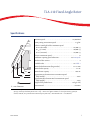
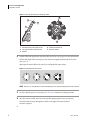
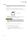
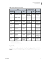
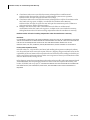
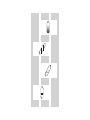
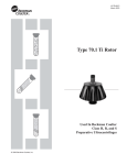
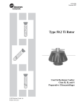
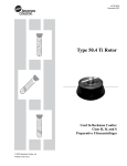
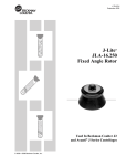
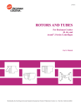
Instructions For Use TLA-110 Fixed-Angle Rotor For Use in the Beckman Coulter Optima MAX-XP, MAX-TL, MAX, MAX-E, TL, TLX, and TL-100 Tabletop Ultracentrifuges PN TL-TB-019AF January 2013 Beckman Coulter, Inc. 250 S. Kraemer Blvd. Brea, CA 92821 U.S.A. TLA-110 Fixed Angle Rotor PN TL-TB-019AF (January 2013) Copyright 1998–2013 Beckman Coulter, Inc. All rights reserved No part of this document may be reproduced or transmitted in any form or by any means, electronic, mechanical, photocopying, recording, or otherwise, without prior written permission from Beckman Coulter, Inc. Beckman Coulter, the stylized logo, Microfuge, and Quick-Seal are trademarks of Beckman Coulter, Inc. and are registered in the USPTO. All other trademarks, service marks, products, or services are trademarks or registered trademarks of their respective holders. Find us on the World Wide Web at: www.beckmancoulter.com Printed in U.S.A. Safety Notice Read all product manuals and consult with Beckman Coulter-trained personnel before attempting to use this equipment. Do not attempt to perform any procedure before carefully reading all instructions. Always follow product labeling and manufacturer’s recommendations. If in doubt as to how to proceed in any situation, contact your Beckman Coulter Representative. Alerts for Warning, Caution, and Note WARNING WARNING indicates a potentially hazardous situation which, if not avoided, could result in death or serious injury. CAUTION CAUTION indicates a potentially hazardous situation, which, if not avoided, may result in minor or moderate injury. It may also be used to alert against unsafe practices. NOTE NOTE is used to call attention to notable information that should be followed during installation, use, or servicing of this equipment. Safety Information for the TLA-110 Rotor Handle body fluids with care because they can transmit disease. No known test offers complete assurance that such fluids are free of micro-organisms. Some of the most virulent—Hepatitis (B and C) viruses, HIV (I–V), atypical mycobacteria, and certain systemic fungi—further emphasize the need for aerosol protection. Handle other infectious samples according to good laboratory procedures and methods to prevent spread of disease. Because spills may generate aerosols, observe proper safety precautions for aerosol containment. Do not run toxic, pathogenic, or radioactive materials in this rotor without taking appropriate safety precautions. Biosafe containment should be used when Risk Group II materials (as identified in the World Health Organization Laboratory Biosafety Manual) are handled; materials of a higher group require more than one level of protection. The rotor and accessories are not designed for use with materials capable of developing flammable or explosive vapors. Do not centrifuge such materials in nor handle or store them near the ultracentrifuge. Although rotor components and accessories made by other manufacturers may fit in the TLA-110 rotor, their safety in this rotor cannot be ascertained by Beckman Coulter. Use of other manufacturers’ components or accessories in the TLA-110 rotor may void the rotor warranty and should be prohibited by your laboratory safety officer. Only the components and accessories listed in this publication should be used in this rotor. PN TL-TB-019AF iii Safety Notice Safety Information for the TLA-110 Rotor Make sure that filled containers are loaded symmetrically into the rotor and that opposing tubes are filled to the same level with liquid of the same density. Make sure that cavities in use have the proper spacers and/or floating spacers inserted before installing the rotor lid. If disassembly reveals evidence of leakage, you should assume that some fluid escaped the rotor. Apply appropriate decontamination procedures to the centrifuge and accessories. Never exceed the maximum rated speed of the rotor and labware in use. Refer to the section on Run Speeds. Do not use sharp tools on the rotor that could cause scratches in the rotor surface. Corrosion begins in scratches and may open fissures in the rotor with continued use. iv PN TL-TB-019AF Contents Safety Notice, iii Alerts for Warning, Caution, and Note, iii Safety Information for the TLA-110 Rotor, iii TLA-110 Fixed-Angle Rotor, 1 Specifications, 1 Description, 2 Preparation and Use, 3 Selecting CsCl Gradients, 12 Typical Examples for Determining CsCl Run Parameters, 15 Care and Maintenance, 16 Returning a Rotor, 19 Supply List, 20 Beckman Coulter, Inc. Ultracentrifuge Rotor Warranty Related Documents v vi Illustrations 1 Tube Cap Orientation for Microfuge Tubes, 4 2 Arranging Tubes in the Rotor., 4 3 Precipitation Curves for the TLA-110 Rotor, 13 4 CsCl Gradients at Equilibrium for the TLA-110 Rotor, 14 vii Tables viii 1 Available Tubes for the TLA-110 Rotor, 7 2 Relative Centrifugal Fields for the TLA-110 Rotor when Using g-Max 3.5-mL Quick-Seal Tubes, 10 3 Relative Centrifugal Fields for the TLA-110 Rotor when Using 5.1-mL Quick-Seal Tubes, 11 TLA-110 Fixed-Angle Rotor Specifications Maximum speed . . . . . . . . . . . . . . . . . . . . . . . . . . . . . . . . . . . . . . 110,000 RPM 28° Density rating at maximum speed . . . . . . . . . . . . . . . . . . . . . . . . . 1.7 g/mL Relative Centrifugal Fielda at maximum speed at rmax (48.5 mm) . . . . . . . . . . . . . . . . . . . . . . . . . . . . . . . . . . . . . 657,000 g at rav (37.2 mm) . . . . . . . . . . . . . . . . . . . . . . . . . . . . . . . . . . . . . . 504,000 g at rmin (26.0 mm) . . . . . . . . . . . . . . . . . . . . . . . . . . . . . . . . . . . . . 353,000 g k factor at maximum speed . . . . . . . . . . . . . . . . . . . . . . . . . . . . . . . . . . . . . 13 Conditions requiring speed reductions . . . . . . . . . . . . . . . . . see Run Speeds Number of tube cavities . . . . . . . . . . . . . . . . . . . . . . . . . . . . . . . . . . . . . . . . . 8 Available tubes . . . . . . . . . . . . . . . . . . . . . . . . . . . . . . . . . . . . . . . . . see Table 1 Nominal tube dimensions (largest tube) . . . . . . . . . . . . . . . . . 13 51 mm Nominal tube capacity . . . . . . . . . . . . . . . . . . . . . . . . . . . . . . . . . . . . . . 5.1 mL rmin rav rmax 1 1. Axis of Rotation Nominal rotor capacity . . . . . . . . . . . . . . . . . . . . . . . . . . . . . . . . . . . . 40.8 mL Approximate acceleration time to maximum speed (fully loaded). . . . . . . . . . . . . . . . . . . . . . . . . . . . . . . . . . . . . . . . . . . . . 4 min Approximate deceleration time from maximum speed (fully loaded). . . . . . . . . . . . . . . . . . . . . . . . . . . . . . . . . . . . . . . . . . . . . 2 min Weight of fully loaded rotor. . . . . . . . . . . . . . . . . . . . . . . . . . . . 1.0 kg (2.2 lb) Rotor material. . . . . . . . . . . . . . . . . . . . . . . . . . . . . . . . . . . . . . . . . . . . titanium a. Relative Centrifugal Field (RCF) is the ratio of the centrifugal acceleration at a specified radius and speed (r2) to the standard acceleration of gravity (g) according to the following formula: RCF = r/g — where r is the radius in millimeters, is the angular velocity in radians per second (2 RPM /60), and g is the standard acceleration of gravity (9807 mm/s2). After substitution: RCF = 1.12r (RPM/1000)2 PN TL-TB-019AF 1 TLA-110 Fixed-Angle Rotor Description Description 1 1. Lid Assembly (366732) 2. Lid O-ring (outer) (854519) 2 4 3. Fluid-Containment Annulus 3 5 4. Lid O-ring (inner) (824412) 5. Rotor Body (366733) Beckman Coulter TLA-110 rotors are manufactured in a facility that maintains certifications to both ISO 9001:2008 and ISO 13485:2003. They are for use with the specified Beckman Coulter centrifuges. The TLA-110 fixed-angle rotor has a tube angle of 28 degrees from the axis of rotation. The rotor can centrifuge up to eight tubes. The rotor is made of titanium and is finished with black polyurethane paint. The lid is made of aluminum and anodized to resist corrosion. A plunger in the lid locks the rotor to the drive hub before beginning the run, and two lubricated O-rings made of Buna-N rubber maintain atmospheric pressure inside the rotor during centrifugation. The tube cavities are numbered to aid in sample identification. The rotor is specially designed with a fluid-containment annulus located below the O-ring sealing surface. The annulus retains fluid that may escape from leaking or overfilled tubes, thereby preventing the liquid from escaping into the instrument chamber. The ultracentrifuge identifies rotor speed during the run by means of a magnetic speed sensor in the instrument chamber and magnets on the bottom of the rotor. This overspeed protection system ensures that the rotor does not exceed its maximum permitted speed. This rotor was tested* to demonstrate containment of microbiological aerosols under normal operating conditions of the associated Beckman Coulter centrifuge, when used and maintained as instructed. Refer to the Warranty at the back of this manual for warranty information. * Validation of microbiological containment was done at an independent third-party testing facility (CAMR, Porton Down, UK, or USAMRIID, Ft. Detrick, MD, U.S.A.). Improper use or maintenance may affect seal integrity and thus containment. 2 PN TL-TB-019AF TLA-110 Fixed-Angle Rotor Preparation and Use Preparation and Use Specific information about the TLA-110 rotor is given here. Information common to this and other rotors is contained in Rotors and Tubes for Tabletop Preparative Ultracentrifuges (publication TLR-IM), which should be used together with this manual for complete rotor and accessory operation. Publication TLR-IM is included in the literature package shipped with the rotor. NOTE Although rotor components and accessories made by other manufacturers may fit in the TLA-110 rotor, their safety in this rotor cannot be ascertained by Beckman Coulter. Use of other manufacturers’ components or accessories in the TLA-110 rotor may void the rotor warranty and should be prohibited by your laboratory safety officer. Only the components and accessories listed in this publication should be used in this rotor. Prerun Safety Checks Read the Safety Notice section at the front of this manual before using the rotor. 1 Inspect the O-rings and plunger mechanism for damage—the high forces generated in this rotor can cause damaged components to fail. 2 Use only tubes and accessories listed in Table 1. 3 Check the chemical compatibilities of all materials used (refer to Chemical Resistances, publication IN-175). Rotor Preparation For runs at other than room temperature, refrigerate or warm the rotor beforehand for fast equilibration. 1 Lightly but evenly lubricate metal threads with Spinkote lubricant (306812). 2 Apply a thin film of silicone vacuum grease (335148) to the two O-rings in the rotor lid. 3 If using 1.5 mL Microfuge tubes, place the adapters into the tube cavities before inserting the tubes. a. Cut the hinges off the caps. b. Face the lift tab of all tubes toward the outside of the rotor (see Figure 1) before installing the rotor lid. PN TL-TB-019AF 3 TLA-110 Fixed-Angle Rotor Preparation and Use Figure 1 Tube Cap Orientation for Microfuge Tubes 4 1 2 3 5 4 1 3 6 8 2 7 5 1. Face tab toward outer edge of rotor 2. Cut hinge off before inserting tube 3. Adapter 4 4. Lift tab should face out 5. Top View of Rotor Load the filled and capped tubes symmetrically into the rotor (see page 6 for tube information). If fewer than eight tubes are being run, they must be arranged symmetrically in the rotor (see Figure 2). Opposing tubes must be filled to the same level with liquid of the same density. Figure 2 Arranging Tubes in the Rotor. NOTE Two, four, six, or eight tubes can be centrifuged per run if they are arranged in the rotor as shown. 5 Use the required spacers, if necessary (see Table 1), to complete the loading operation. 6 After the rotor is loaded, insert it into the portable polypropylene rotor vise (346133). Place the lid on the rotor and tighten it firmly to the right (clockwise) by hand. No tool is required. 4 PN TL-TB-019AF TLA-110 Fixed-Angle Rotor Preparation and Use Operation 1 Use an absorbent towel to wipe off condensation from the rotor, then carefully place the rotor on the drive hub. 2 Lock the rotor in place by gently pressing the plunger down until you feel it click. When you remove your finger, the plunger will remain flush with the rotor body if it is properly engaged. 1 1. Plunger Engaged If the plunger pops up, repeat the procedure. The Optima MAX-TL, MAX-XP, MAX, and MAX-E ultracentrifuges automatically secure the rotor to the drive shaft without the need for engaging the plunger. CAUTION In all ultracentrifuge models except the Optima MAX-TL, MAX-XP, MAX, and MAX-E, it is very important to lock the rotor in place before beginning the run to ensure that the rotor remains seated during centrifugation. Failure to lock the rotor in place before beginning the run may result in damage to both rotor and instrument. 3 Refer to the instrument instruction manual for ultracentrifuge operation. 4 For additional operating information, see the following: • Run Times, page 9, for using k factors to adjust run durations. • Run Speeds, page 9, for information about speed limitations. • Selecting CsCl Gradients, page 12, for methods to avoid CsCl precipitation during centrifugation. PN TL-TB-019AF 5 TLA-110 Fixed-Angle Rotor Preparation and Use Removal and Sample Recovery CAUTION If disassembly reveals evidence of leakage, you should assume that some fluid escaped the rotor. Apply appropriate decontamination procedures to the centrifuge and accessories. 1 To release the plunger at the end of the run, gently press it down until you feel it click. When you remove your finger the plunger will pop up to its released position. 1 1. Plunger Released 2 Remove the rotor from the ultracentrifuge and place it in the rotor vise. 3 Remove the lid by unscrewing it to the left (counterclockwise). 4 Use a tube removal tool to remove the spacers and tubes. Tubes and Accessories The TLA-110 rotor uses tubes and accessories listed in Table 1. Be sure to use only those items listed, and to observe the maximum speed limits shown. Refer to Chemical Resistances (publication IN-175) for information on the chemical compatibilities of tube and accessory materials. Temperature Limits • Plastic tubes have been centrifuge tested for use at temperatures between 2 and 25°C. For centrifugation at other temperatures, pretest tubes under anticipated run conditions. • If plastic containers are frozen before use, make sure that they are thawed to at least 2°C prior to centrifugation. 6 PN TL-TB-019AF TLA-110 Fixed-Angle Rotor Preparation and Use Table 1 Available Tubes for the TLA-110 Rotora Tube Dimensions and Volume Required Accessory Description Part Number Part Number Max. Speed/ RCF/k Factor 13 51 mm 5.1 mL Quick-Seal polyallomer, bell top 343776 (pkg/100) Polyphenylene oxide (PPO) floating spacer 362307 (pkg/8) 110,000 RPM 627,000 g 13 13 48 mm 4.7 mL OptiSeal b bell-top 361621 (pkg/56) Polyethermide (PEI) spacer 361676 (pkg/2) 110,000 RPM 657,000 g 12 13 32 mm 3.5 mL Quick-Seal polyallomer, bell-top 349621 (pkg/50) Polyphenylene oxide (PPO) floating spacer 360270 (pkg/8) 110,000 RPM 657,000 g 7 13 56 mm 3.2 mL c thickwall polycarbonate 362305 (pkg/50) none — 110,000 RPM 657,000 g 15 13 56 mm 3.2 mL thickwall polyallomer 362333 (pkg/50) none — 70,000 RPM 266,000 g 37 13 25 mm 2.0 mL Quick-Seal polyallomer, bell-top 345829 (pkg/50) Polyphenylene oxide (PPO) floating spacer 360270 (pkg/8) 110,000 RPM 657,000 g 5 11 39 mm 1.5 mL Microfuge, polyallomer (capped) 357448 (pkg/500) Polyphenylene oxide (PPO) adapter 360951 (pkg/8) 70,000 RPM d 206,000 g 19 11 47 mm 1.5 mL Microfuge, polypropylene (capped) Acetal (POM) adapter 393238 (pkg/8) 110,000 RPM 536,000 g 9 Labcon 3611-870-000 (pkg/500) Description a. Use only the items listed here and observe maximum fill volumes and speeds shown. b. Includes disposable plastic plugs. c. Minimum fill level for this tube is 1.6 mL. d. At 40°C, speed must be reduced to 59,000 RPM. OptiSeal Tubes OptiSeal tubes come with plastic plugs and can be quickly and easily prepared for use. With the tube spacer in place, the g force during centrifugation ensures a tight, reliable seal that protects your samples. PN TL-TB-019AF 7 TLA-110 Fixed-Angle Rotor Preparation and Use 1 Place the tubes in the rack and fill each tube to the base of the stem, leaving no fluid in the stem. Overfilling the tube can cause spillage when the plug is inserted or can compromise seal integrity. However, too much air can cause excessive tube deformation, disrupting gradients and sample bands. Refer to Using OptiSeal Tubes (publication IN-189), included in each box of tubes, for detailed information on the use and care of OptiSeal tubes. 1 2 6 3 4 5 1. Spacer 2. Plug 3. Stem 4. Meniscus 5. Tube 6. Base of Stem Quick-Seal Tubes Quick-Seal tubes must be sealed prior to centrifugation. These tubes are heat sealed and do not need caps; however, spacers are required on top of the tubes when they are loaded into the rotor. 1 Fill Quick-Seal tubes leaving a small bubble of air at the base of the neck. Do not leave a large air space—too much air can cause excessive tube deformation. g-Max Spacer Refer to Rotors and Tubes for detailed information on the use and care of Quick-Seal tubes. Some of the tubes listed in Table 1 are part of the g-Max system. The g-Max system uses a combination of small bell-top Quick-Seal tubes and floating spacers (also called g-Max spacers). This means that you can run the shorter tubes listed in the table in the TLA-110 rotor without reduction in g force. Additional information about the g-Max system is available in publication DS-709B. Thickwall Tubes Thickwall polyallomer and polycarbonate tubes can be run partially filled (at least half filled) without caps, but all opposing tubes for a run must be filled to the same level with liquid of the same density. Do not overfill capless tubes; be sure to note the reduction in run speed shown in Table 1. Microfuge Tubes The 1.5-mL microfuge tubes, with attached caps, are made of clear polyallomer. The tubes are placed in adapters for use in this rotor. All opposing tubes for a run must be filled with liquid of the same density. Be sure to note the run speed reduction shown in Table 1. 8 PN TL-TB-019AF TLA-110 Fixed-Angle Rotor Preparation and Use Run Times The k factor of the rotor is a measure of the rotor’s pelleting efficiency. Beckman Coulter has calculated the k factors for all of its preparative rotors at maximum rated speed and using full tubes. The k factor is calculated from the formula: ln ( rmax ⁄ rmin ) 10 13 - × -----------k = ---------------------------------3600 ω2 EQ 1 where is the angular velocity of the rotor in radians per second ( = 0.105 RPM), rmax is the maximum radius, and rmin is the minimum radius. After substitution: (2.533 × 10 11) ln ( rmax ⁄ rmin ) k = -----------------------------------------------------------------------( RPM ) 2 EQ 2 Use the k factor in the following equation to estimate the run time t (in hours) required to pellet particles of known sedimentation coefficient s (in Svedberg units, S). t = k--s EQ 3 Run times can be estimated for centrifugation at less than maximum speed by adjusting the k factor as follows: 110,000 k adj = k ⎛ ----------------------------------------⎞ ⎝actual run speed ⎠ 2 EQ 4 Run times can also be estimated from data established in prior experiments if the k factor of the previous rotor is known. For any two rotors, a and b: ka t ----a- = -----tb kb EQ 5 For more information on k factors see Use of k Factor for Estimating Run Times from Previously Established Run Conditions (publication DS-719). Run Speeds The centrifugal force at a given radius in a rotor is a function of speed. Comparisons of forces between different rotors are made by comparing the rotors’ relative centrifugal fields (RCF). When rotational speed is adjusted so that identical samples are subjected to the same RCF in two different rotors, the samples are subjected to the same force. The RCF at a number of rotor speeds is provided in Table 2 and Table 3. PN TL-TB-019AF 9 TLA-110 Fixed-Angle Rotor Preparation and Use Table 2 Relative Centrifugal Fields for the TLA-110 Rotor when Using g-Max 3.5-mL Quick-Seal Tubesa Relative Centrifugal Field ( g) Rotor Speed (RPM) At rmax (48.5 mm) At rav (37.2 mm) At rmin (26.0 mm) k Factor* 110,000 675,000 504,000 353,000 13 105,000 599,000 459,000 321,000 14 100,000 543,000 417,000 291,000 16 95,000 490,000 376,000 263,000 17 90,000 440,000 338,000 236,000 19 85,000 393,000 301,000 210,000 22 80,000 348,000 267,000 186,000 25 75,000 306,000 234,000 164,000 28 70,000 266,000 204,000 143,000 32 65,000 230,000 176,000 123,000 37 60,000 196,000 150,000 105,000 44 55,000 164,000 126,000 88,100 52 50,000 136,000 104,000 72,800 63 45,000 110,000 84,400 59,000 78 40,000 86,900 66,700 46,600 99 35,000 66,600 51,000 35,700 129 30,000 48,900 37,500 26,200 175 25,000 34,000 26,000 18,200 253 20,000 21,700 16,700 11,700 395 a. Entries in this table are calculated from the formula RCF = 1.12r (RPM/1000)2 and then rounded to three significant digits. Relative Centrifugal Fields (RCF) for the TLA-110 Rotor (3.5-mL Quick-Seal Tube) 700,000 600,000 RCF (x g) 500,000 rmax 400,000 rav rmin 300,000 200,000 100,000 0 0 20,000 40,000 60,000 80,000 100,000 110,000 Speed (rpm) 10 PN TL-TB-019AF TLA-110 Fixed-Angle Rotor Preparation and Use Table 3 Relative Centrifugal Fields for the TLA-110 Rotor when Using 5.1-mL Quick-Seal Tubesa Relative Centrifugal Field ( g) Rotor Speed (RPM) At rmax (48.6 mm) At rav (33.6 mm) At rmin (18.4 mm) k Factor* 110,000 658,000 455,000 249,000 20 105,000 600,000 414,000 227,000 22 100,000 544,000 376,000 206,000 25 95,000 491,000 339,000 186,000 27 90,000 441,000 304,000 167,000 30 85,000 393,000 272,000 149,000 34 80,000 348,000 241,000 132,000 38 75,000 306,000 212,000 116,000 44 70,000 267,000 184,000 101,000 50 65,000 230,000 159,000 87,100 58 60,000 196,000 135,000 74,200 68 55,000 165,000 114,000 62,300 81 50,000 136,000 93,900 51,500 98 45,000 110,000 76,100 41,700 121 40,000 87,100 60,100 33,000 154 35,000 67,000 46,000 25,300 201 30,000 49,000 33,100 18,600 273 25,000 34,000 23,500 12,900 394 20,000 21,800 15,000 8,240 615 a. Entries in this table are calculated from the formula RCF = 1.12r (RPM/1000)2 and then rounded to three significant digits. Relative Centrifugal Fields (RCF) for the TLA-110 Rotor (5.1-mL Quick-Seal Tube) 700,000 600,000 RCF (x g) 500,000 rmax rav 400,000 rmin 300,000 200,000 100,000 0 0 20,000 40,000 60,000 80,000 100,000 110,000 Speed (rpm) PN TL-TB-019AF 11 TLA-110 Fixed-Angle Rotor Selecting CsCl Gradients Speeds must be reduced under the following circumstances: 1. If nonprecipitating solutions more dense than 1.7 g/mL are centrifuged, the maximum allowable run speed must be reduced according to the following equation: reduced maximum speed = (110,000 RPM) 1.7 g/mL--------------------ρ EQ 6 where is the density of the tube contents. This speed reduction will protect the rotor from excessive stresses due to the added tube load. Note, however, that the use of this formula may still produce maximum speed values that are higher than the limitations imposed by the use of certain tubes or adapters. In such cases, use the lower of the two values. 2. Further speed limits must be imposed when CsCl or other self-forming-gradient salts are centrifuged, as equation (6) does not predict concentration limits/speeds that are required to avoid precipitation of salt crystals. Precipitation during centrifugation would alter the density distribution of CsCl and this would change the position of the sample bands. Figure 3 and Figure 4, together with the description and examples below, show how to reduce run speeds when using CsCl gradients. Selecting CsCl Gradients Precipitation during centrifugation would alter density distribution, and this would change the position of the sample bands. Curves in Figure 3 and Figure 4 are provided up to the maximum rated speed of the rotor. NOTE The curves in Figure 3 and Figure 4 are for solutions of CsCl salt dissolved in distilled water only. If other salts are present in significant concentrations, the overall CsCl concentration may need to be reduced. Rotor speed is used to control the slope of a CsCl density gradient, and must be limited so that CsCl precipitation is avoided. Speed and density combinations that intersect on or below the curves in Figure 3 ensure that CsCl will not precipitate during centrifugation in the TLA-110 rotor. Curves are provided at two temperatures: 20°C (black curves) and 4°C (gray curves). The reference curves in Figure 4 show gradient distribution at equilibrium. Each curve in Figure 4 is within the density limits allowed for the TLA-110 rotor: each curve was generated for a single run speed using the maximum allowable homogeneous CsCl densities (one for each fill level) that avoid precipitation at that speed. (The gradients in Figure 4 can be generated from step or linear gradients, or from homogeneous solutions. But the total amount of CsCl in solution must be equivalent to a homogeneous solution corresponding to the concentrations specified in Figure 3.) Figure 4 can also be used to approximate the banding positions of sample particles. 12 PN TL-TB-019AF TLA-110 Fixed-Angle Rotor Selecting CsCl Gradients Figure 3 Precipitation Curves for the TLA-110 Rotor* 1.90 1.80 1/4 Homogeneous CsCl Solution (g/mL) 1.70 1/4 fu ll 3/4 1/2 1/ 2 1.60 3/ 4 1.50 TLA-110 ROTOR fu ll = 20°C 1.40 = 4°C 1.30 1.20 0 10 20 30 40 50 60 70 80 90 100 110 Rotor Speed (K RPM) * Using combinations of rotor speeds and homogeneous CsCl solution densities that intersect on or below these curves ensures that CsCl will not precipitate during centrifugation. PN TL-TB-019AF 13 TLA-110 Fixed-Angle Rotor Selecting CsCl Gradients Figure 4 CsCl Gradients at Equilibrium for the TLA-110 Rotor* 1.9 1.8 1.7 0 RPM 50,00 0 RPM Density (g/mL) 1.6 50,00 M 0 RP 65,00 1.5 M 0 RP 65,00 PM 0R 00 80, 1.4 M 00 0 80, RP 1.3 1.2 9 0R 5,00 00 95,0 M PM 0 ,00 0 11 RPM TLA-110 ROTOR RP = 20°C M P 0R = 4°C ,00 0 11 1.1 1.0 18.0 21.7 25.5 29.2 32.9 36.7 40.4 44.2 47.9 Distance from Axis of Rotation (mm) * Centrifugation of homogeneous CsCl solutions at the maximum allowable speeds (from Figure 3) results in gradients presented here. The homogeneous CsCl solution density used to generate each curve is printed along the curve. 14 PN TL-TB-019AF TLA-110 Fixed-Angle Rotor Typical Examples for Determining CsCl Run Parameters Typical Examples for Determining CsCl Run Parameters Example A: A separation that is done frequently is the banding of plasmic DNA in cesium chloride with ethidium bromide. The starting density of the CsCl solution is 1.55 g/mL. In this separation the covalently closed, circular plasmid bands at a density of 1.57 g/mL, while the nicked and linear species band at 1.53 g/mL. At 20°C, where will particles band? 1 In Figure 3, find the curve that corresponds to the desired run temperature (20°C) and fill volume (three-quarters full). The maximum allowable rotor speed is determined from the point where this curve intersects the homogeneous CsCl density (86,000 RPM). 2 In Figure 4, sketch in a horizontal line corresponding to each particle’s buoyant density. 3 Mark the point in the figure where each particle density intersects the curve corresponding to the selected run speed and temperature. 4 Particles will band at these locations across the tube diameter at equilibrium during centrifugation. 1 3 2 1. At Speed 2. At Rest in Rotor 6 3. Upright 5 4. Pelleted Material 5. Bands 4 6. Floating Components In this example, particles will band about 36 and 38 mm from the axis of rotation, about 2 mm of centerband-to-centerband separation at the rotor’s 28-degree tube angle. When the tube is removed from the rotor and held upright (vertical and stationary), there will be about 2.27 mm of centerband-to-centerband separation. This interband distance, dup, can be calculated from the formula: dθ d up = ----------cos θ EQ 7 where d is the interband distance when the tube is held at an angle, , in the rotor. PN TL-TB-019AF 15 TLA-110 Fixed-Angle Rotor Care and Maintenance Example B: Knowing particle buoyant densities (e.g., 1.59 and 1.54 g/mL), how do you achieve good separation? 1 In Figure 4, sketch in a horizontal line corresponding to each particle’s buoyant density. 2 Select the curve at the desired temperature (4°C) and fill volume (full) that gives the best particle separation. 3 Note the run speed along the selected curve (65,000 RPM). 4 From Figure 3, select the maximum homogeneous CsCl density (in this case, 1.59 g/mL) that corresponds to the temperature and run speed established above. These parameters will provide the particle-banding pattern selected in Step 2. In this example, particles will band at about 31 and 34 mm from the axis of rotation (about 3 mm apart). When the tube is held upright there will be about 3.4 mm of center-of-band to center-ofband separation. Care and Maintenance Maintenance NOTE Do not use sharp tools on the rotor that could cause scratches in the rotor surface. Corrosion begins in scratches and may open fissures in the rotor with continued use. 1 2 3 1. Lid Assembly (366732) 4 2. Lid O-ring (outer) (854519) 5 3. Check for Corrosion 4. Threads 5. Lid O-ring (inner) (824412) 1 Regularly lubricate the metal threads in the rotor plugs with a thin, even coat of Spinkote lubricant. Failure to keep these threads lubricated can result in damaged threads. 16 PN TL-TB-019AF TLA-110 Fixed-Angle Rotor Care and Maintenance 2 Regularly apply silicone vacuum grease to the O-rings. Replace O-rings about twice a year or whenever worn or damaged. Refer to Chemical Resistances (publication IN-175) for the chemical compatibilities of rotor and accessory materials. Your Beckman Coulter representative provides contact with the Field Rotor Inspection Program and the rotor repair center. Cleaning Wash the rotor and rotor components immediately if salts or other corrosive materials are used or if spillage has occurred. Do not allow corrosive materials to dry on the rotor. Under normal use, wash the rotor frequently (at least weekly) to prevent buildup of residues. 1 Remove the O-rings before washing. 2 Wash the rotor and lid in a mild detergent, such as Solution 555 (339555), that won’t damage the rotor. Dilute the detergent with water (10 parts water to 1 part detergent). The Rotor Cleaning Kit contains two plastic-coated brushes and two quarts of Solution 555 for use with rotors and accessories. NOTE Do not wash rotor components in a dishwasher. Do not soak in detergent solution for long periods, such as overnight. 3 Rinse the cleaned rotor and components with distilled water. 4 Air-dry the rotor and lid upside down. Do not use acetone to dry the rotor. 5 PN TL-TB-019AF Apply a thin, even coat of silicone vacuum grease to both lid O-rings before replacing them in the grooves in the lid. 17 TLA-110 Fixed-Angle Rotor Care and Maintenance 6 Clean metal threads as necessary (at least every 6 months). a. Use a brush and concentrated Solution 555. b. Dilute the detergent with water (10 parts water to 1 part detergent). c. Rinse and dry thoroughly, then lubricate lightly but evenly with Spinkote to coat all threads. 1 1. Threads 7 Periodically remove the O-rings and wipe clean as necessary. a. Clean the O-ring grooves with a cotton-tipped swab. b. Reapply a light film of silicone vacuum grease. Decontamination If the rotor or other components are contaminated with radioactive, toxic, or pathogenic materials, follow appropriate decontamination procedures as outlined by appropriate laboratory safety guidelines and/or other regulations. Consult Chemical Resistances (IN-175) to select an agent that will not damage the rotor Sterilization and Disinfection • The rotor and all rotor components can be autoclaved at 121°C for up to one hour. Remove the lid from the rotor and place the rotor, lid, and O-ring in the autoclave upside down. • Ethanol (70%) or hydrogen peroxide (6%) may be used on all rotor components, including those made of plastic. Bleach (sodium hypochlorite) may be used, but may cause discoloration of anodized surfaces. Use the minimum immersion time for each solution, per laboratory standards. 18 PN TL-TB-019AF TLA-110 Fixed-Angle Rotor Returning a Rotor CAUTION Ethanol is a flammability hazard. Do not use it in or near operating ultracentrifuges. While Beckman Coulter has tested these methods and found that they do not damage the rotor or components, no guarantee of sterility or disinfection is expressed or implied. When sterilization or disinfection is a concern, consult your laboratory safety officer regarding proper methods to use. Storage When it is not in use, store the rotor in a dry environment (not in the instrument) with the lid removed to allow air circulation so moisture will not collect in the tube cavities. Returning a Rotor Before returning a rotor or accessory for any reason, prior permission must be obtained from Beckman Coulter, Inc. The authorization form may be obtained from your local Beckman Coulter sales office. The form, entitled Returned Material Authorization (RMA) for United States returns or Returned Goods Authorization (RGA) for international returns, should contain the following information: • rotor type and serial number, • history of use (approximate frequency of use), • reason for the return, • original purchase order number, billing number, and shipping number, if possible, • name and email address of the person to be notified upon receipt of the rotor or accessory at the factory, • name and email address of the person to be notified about repair costs, etc. To protect our personnel, it is the customer’s responsibility to ensure that all parts are free from pathogens and/or radioactivity. Sterilization and decontamination must be done before returning the parts. Smaller items (such as tubes, bottles, etc.) should be enclosed in a sealed plastic bag. All parts must be accompanied by a note, plainly visible on the outside of the box or bag, stating that they are safe to handle and that they are not contaminated with pathogens or radioactivity. Failure to attach this notification will result in return or disposal of the items without review of the reported problem. Use the address label printed on the form when mailing the rotor and/or accessories. Customers located outside the United States should contact their local Beckman Coulter office. PN TL-TB-019AF 19 TLA-110 Fixed-Angle Rotor Supply List Supply List To order parts and supplies or obtain publications referenced in this manual, call Beckman Coulter Customer Service at 1-800-742-2345 (U.S.A. or Canada) or contact your local Beckman Coulter Representative. Referenced publications may also be available at www.beckmancoulter.com. See the Beckman Coulter Ultracentrifuge Rotors, Tubes & Accessories catalog (BR-8101, available at www.beckmancoulter.com) for detailed information on ordering parts and supplies. For your convenience, a partial list is given below. Replacement Rotor Parts Description Part Number TLA-110 rotor assembly 366730 Lid assembly 366732 Lid O-ring (outer) 854519 Lid O-ring (inner) 824412 Cap and plunger assembly 349477 Spring 347903 Rotor vise 346133 Other NOTE For MSDS information, go to the Beckman Coulter website at www.beckmancoulter.com. Description Tubes and accessories 20 Part Number seeTable 1 Tube rack 355872 Quick-Seal Cordless Tube Topper kit, 60 Hz 358312 Quick-Seal Cordless Tube Topper kit, 50 Hz (Europe) 358313 Quick-Seal Cordless Tube Topper kit, 50 Hz (Great Britain) 358314 Quick-Seal Cordless Tube Topper kit, 50 Hz (Australia) 358315 Quick-Seal Cordless Tube Topper kit, 50-Hz (Canada) 367803 Tube Topper rack 348122 OptiSeal tube rack assembly 361638 Spacer removal tool (for 3.5-mL and 2.0-mL Quick-Seal tubes) 338765 Spacer removal tool (for OptiSeal tubes) 338765 Tube removal tool 361668 PN TL-TB-019AF TLA-110 Fixed-Angle Rotor Supply List Description PN TL-TB-019AF Part Number Curved hemostat (6-in.) 927208 Straight hemostat (6-in.) 961519 Fraction Recovery System 342025 Fraction Recovery System Adapter Kit for TL-series tubes 347828 Beckman Coulter CentriTube Slicer 347960 CentriTube Slicer replacement blades (pkg of 10) 348299 CentriTube Slicer adapter (for 13-mm tubes) 354526 Spinkote lubricant (2 oz) 306812 Silicone vacuum grease (1 oz) 335148 Rotor Cleaning Kit 339558 Rotor Cleaning Brush 347404 Solution 555 (1 qt) 339555 21 TLA-110 Fixed-Angle Rotor Supply List 22 PN TL-TB-019AF Beckman Coulter, Inc. Ultracentrifuge Rotor Warranty All Beckman Coulter ultracentrifuge Fixed Angle, Vertical Tube, Near Vertical Tube, Swinging Bucket, and Airfuge rotors are warranted against defects in materials or workmanship for the time periods indicated below, subject to the Warranty Conditions stated below. Preparative Ultracentrifuge Rotors. . . . . . . . . . . . . . . . . . . . . . . . . . . . . . . . . . . . . . 5 years — No Proration Analytical Ultracentrifuge Rotors . . . . . . . . . . . . . . . . . . . . . . . . . . . . . . . . . . . . . . . 5 years — No Proration ML and TL Series Ultracentrifuge Rotors . . . . . . . . . . . . . . . . . . . . . . . . . . . . . . . . . 5 years — No Proration Airfuge Ultracentrifuge Rotors . . . . . . . . . . . . . . . . . . . . . . . . . . . . . . . . . . . . . . . . . 1 year — No Proration For Zonal, Continuous Flow, Component Test, and Rock Core Ultracentrifuge Rotors, see separate warranty. Warranty Conditions (as applicable) 1. This warranty is valid for the time periods indicated above from the date of shipment to the original Buyer by Beckman Coulter or an authorized Beckman Coulter representative. 2. Maintain one copy of this software for backup purposes (the backup copy shall be supplied by Beckman Coulter); 3. This warranty covers the Beckman Coulter Centrifuge Systems only (including but not limited to the centrifuge, rotor, and accessories) and Beckman Coulter shall not be liable for damage to or loss of the user’s sample, non-Beckman Coulter tubes, adapters, or other rotor contents. 4. This warranty is void if the Beckman Coulter Centrifuge System is determined by Beckman Coulter to have been operated or maintained in a manner contrary to the instructions in the operator’s manual(s) for the Beckman Coulter Centrifuge System components in use. This includes but is not limited to operator misuse, abuse, or negligence regarding indicated maintenance procedures, centrifuge and rotor classification requirements, proper speed reduction for the high density of certain fluids, tubes, and tube caps, speed reduction for precipitating gradient materials, and speed reduction for high-temperature operation. 5. Rotor bucket sets purchased concurrently with or subsequent to the purchase of a Swinging Bucket Rotor are warranted only for a term co-extensive with that of the rotor for which the bucket sets are purchased. 6. This warranty does not cover the failure of a Beckman Coulter rotor in a centrifuge not of Beckman Coulter manufacture, or if the rotor is used in a Beckman Coulter centrifuge that has been modified without the written permission of Beckman Coulter, or is used with carriers, buckets, belts, or other devices not of Beckman Coulter manufacture. 7. Rotor parts subject to wear, including but not limited to rotor O-rings, VTi, NVT, TLV, MLN, and TLN rotor tube cavity plugs and gaskets, tubing, tools, optical overspeed disks, bearings, seals, and lubrication are excluded from this warranty and should be frequently inspected and replaced if they become worn or damaged. 8. Keeping a rotor log is not mandatory, but may be desirable for maintenance of good laboratory practices. Repair and Replacement Policies 1. If a Beckman Coulter rotor is determined by Beckman Coulter to be defective, Beckman Coulter will repair or replace it, subject to the Warranty Conditions. A replacement rotor will be warranted for the time remaining on the original rotor’s warranty. 2. If a Beckman Coulter centrifuge is damaged due to a failure of a rotor covered by this warranty, Beckman Coulter will supply free of charge (i) all centrifuge parts required for repair (except the drive unit, which will be replaced at the then current price less a credit determined by the total number of revolutions or years completed, provided that such a unit was manufactured or rebuilt by Beckman Coulter), and (ii) if the centrifuge is currently covered by a Beckman Coulter warranty or Full Service Agreement, all labor necessary for repair of the centrifuge. PN TL-TB-019AF Warranty-1 Beckman Coulter, Inc. Ultracentrifuge Rotor Warranty 3. 4. 5. If a Beckman Coulter rotor covered by this warranty is damaged due to a malfunction of a Beckman Coulter ultracentrifuge covered by an Ultracentrifuge System Service Agreement, Beckman Coulter will repair or replace the rotor free of charge. If a Beckman Coulter rotor covered by this warranty is damaged due to a failure of a Beckman Coulter tube, bottle, tube cap, spacer, or adapter, covered under the Conditions of this Warranty, Beckman Coulter will repair or replace the rotor and repair the instrument as per the conditions in policy point (2) above, and the replacement policy. Damage to a Beckman Coulter rotor or instrument due to the failure or malfunction of a non-Beckman Coulter tube, bottle, tube cap, spacer, or adapter is not covered under this warranty, although Beckman Coulter will assist in seeking compensation under the manufacturer’s warranty. Beckman Coulter will assist in seeking compensation under the manufacturer’s warranty. Disclaimer IT IS EXPRESSLY AGREED THAT THE ABOVE WARRANTY SHALL BE IN LIEU OF ALL WARRANTIES OF FITNESS AND OF THE WARRANTY OF MERCHANTABILITY AND BECKMAN COULTER, INC. SHALL HAVE NO LIABILITY FOR SPECIAL OR CONSEQUENTIAL DAMAGES OF ANY KIND WHATSOEVER ARISING OUT OF THE MANUFACTURE, USE, SALE, HANDLING, REPAIR, MAINTENANCE, OR REPLACEMENT OF THE PRODUCT. Factory Rotor Inspection Service Beckman Coulter, Inc., will provide free mechanical and metallurgical inspection in Indianapolis, Indiana, USA, of any Beckman Coulter rotor at the request of the user. (Shipping charges to Beckman Coulter are the responsibility of the user.) Rotors will be inspected in the user’s laboratory if the centrifuge in which they are used is covered by an appropriate Beckman Coulter Service Agreement. Contact your local Beckman Coulter office for details of service coverage or cost. Before shipping, contact the nearest Beckman Coulter Sales and Service office and request a Returned Goods Authorization (RGA) form and packaging instructions. Please include the complete rotor assembly, with buckets, lid, handle, tube cavity caps, etc. A SIGNED STATEMENT THAT THE ROTOR AND ACCESSORIES ARE NON-RADIOACTIVE, NON-PATHOGENIC, NON-TOXIC, AND OTHERWISE SAFE TO SHIP AND HANDLE IS REQUIRED. Warranty-2 PN TL-TB-019AF Related Documents Rotors and Tubes for Beckman Coulter Tabletop Preparative Ultracentrifuges (TLR-IM-9) Additional References • Chemical Resistances for Beckman Coulter Centrifugation Products (IN-175) • Rotors • Using OptiSeal Tubes (IN-189) • Tubes and Accessories • • Using Tubes and Accessories Ultracentrifuge Rotors, Tubes, and Accessories catalog (BR-8101) • Using Rotors • • Care and Maintenance g-Max System: Short Pathlengths in High Force Fields (DS-709B) • Chemical Resistances • The Use of Cesium Chloride Curves • Gradient Materials • References Available in hard copy or electronic pdf by request. Also available at www.beckmancoulter.com Available in electronic pdf or CD-ROM by request. www.beckmancoulter.com © 2013 Beckman Coulter, Inc. All Rights Reserved