1
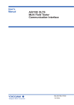
Ultimate-X series
HIGH PERFORMANCE TRUE ON-LINE
DOUBLE CONVERSION UPS
LEN.MAN.UPS.076 Rev.2.00/2003
CONTENTS
Safety Instruction
Introduction
Front and Rear Panel
Installation
Operation
Troubleshooting
Customer Support
Maintenance
1
3
6
9
9
10
11
11
-1-
SAFETY INSTRUCTIONS
Please read and follow this user’s manual carefully and completely.
Important : Please keep this user’s manual for later reference. It consists of
Introduction, Front and Rear Panel, Installation and Operation, Troubleshooting,
Customer Support and Maintenance
If the UPS does not operate properly and you cannot solve the problem
using the troubleshooting information in this user’s manual, please contact
your LEONICS local distributors, LEONICS Service Center, send e-mail to
[email protected] or visit www.leonics.com.
To help you much more quickly when contact us, please record
the following information:
LEONICS UPS model
: ____________________________
Serial number of your UPS : ____________________________
Purchased date
: ____________________________
Purchased from
: ____________________________
-2-
1.1 General safety instruction
1.1.1 DO NOT work alone under hazardous condition
1.1.2 Short circuit current in conductor may cause severe skin burn.
1.1.3 Must contact certified person when user wants to connect any equipment to
utility power line.
1.1.4 Check whether the cables, receptacles, power source are always at good
conditions.
1.1.5 To reduce short circuit risk, if you are not sure whether you have ground
system, disconnect UPS from utility power every time before you connect any
loads to UPS. After connect all loads to UPS already, then reconnect the UPS to
utility power.
1.1.6 DO NOT touch any metal parts of the equipments when connected to UPS
1.1.7 When connect or disconnect communication cables between equipments,
should use only one hand. This is to avoid electric shock from contact
2 surfaces which ground has different potential voltage.
1.1.8 Recommend to connect UPS to 3-wire power source (2 poles + ground) which
connects to branch circuit or fuse or automatic cut out
1.2 Caution! Safety instruction for install and operate UPS
1.2.1 Should install UPS in dry area with good ventilation, low humidity, no chemical
particles, no flammable substances. Avoid installing UPS near radio transmission station, heat dissipation equipment, or direct to sunlight.
1.2.2 UPS has ventilation grills on the back and sides. To help UPS has good ventilation, DO NOT block ventilation grill.
1.2.3 Should connect UPS to utility line and turn on all the time.
1.2.4 When user wants to connect computer interface to UPS, turn off power switch
and disconnect cables from utility line.
1.2.5 Turn on UPS before turn on loads to prevent surge from your loads.
1.2.6 DO NOT connect utility power to UPS OUTPUT. This may cause damage to
your UPS.
1.2.7 When heavy rain, please avoid using electronic instruments including UPS to
prevent it from lightning.
-3-
1.2.8 Use soft cloth to clean UPS when it is OFF. DO NOT clean it with solvents.
1.2.9 DO NOT use UPS with life recovery instruments. The failure of UPS may cause
life recovery instruments failure or effect to their performance or effect to safety
system of those instruments.
1.3 Warning! Safety instruction for battery
1.3.1 There are batteries inside the UPS. Although user has disconnected it from
utility power line, the UPS OUTLET or OUTPUT terminal are still has electricity.
Be careful of electric shock.
1.3.2 The internal parts of UPS may conduct electric current which is dangerous to
user. UPS has no user serviceable parts. DO NOT remove or disassemble any
parts of the UPS. If the user wants to repair the UPS, contact us or our nearest
service center.
1.3.3 In case that user does not use or keep UPS for a long time, to preserve the
battery life, please follow the below instruction
1.3.3.1 Turn off power switch and unplug input cable from power source
1.3.3.2 In case that user does not use UPS for a long time. User should re
charge battery every 3 months by plugging the input cable to power
source and turn the UPS on for at least 8 hours.
INTRODUCTION
2.1 General
Leonics Ultimate-X series UPS is a True On-Line Double Conversion
uninterruptible power supply which is the highest efficiency UPS system available in the
present market. It is able to protect all kinds of power problems and suitable for any
power sensitive electrical appliance and electronic equipments such as computers, communication equipments, medical instruments, electronic scales, measuring instruments,
scientific equipments, and etc.
-4-
2.2 How Leonics Ultimate-X series UPS works
-5-
2.2.3 When utility power fail but loads are normal
2.2.1 When utility power and loads are normal
Above diagram shows how UPS works when utility power (AC line) is
normal and UPS has less than 100% load. UPS converts utility power from
alternative current (AC) to direct current (DC) at RECTIFIER. Some of the DC
power flow to charge battery to be backup power and the rest flow directly to
INVERTER to invert power to high quality and stable AC power. Then, supply
to load.
2.2.2 When utility power is normal but overload
Above diagram shows how UPS works when utility power is normal and
UPS has more than 100% load. UPS converts utility power at RECTIFIER to charge
battery only. The power supplied to load is from utility line.
Above diagram shows how UPS works when utility power fail and UPS has
less than 100% load. UPS draws backup power from battery to invert to AC
power and continuously supplies to load.
2.2.4 Use maintenance bypass switch when UPS is malfunction (option)
Above diagram shows how system works when UPS is malfunction. User is
allow to temporary run the system by turning the manual bypass switch from
Auto to Bypass position. All loads will get power supplied directly from utility
line. Then, contact us or our nearest service center.
-7-
-6-
FRONT AND REAR PANEL
3.1 Front panel
3.1.1 POWER ON / ALARM SILENCE Press this button to turn the UPS on and mute
alarm sound.
3.1.2 POWER OFF Press this button to turn the UPS off.
3.1.3 LINE The indicator is displayed utility power status
ON
shows that input voltage is normal.
FAST BLINK shows that input voltage is high.
SLOW BLINK shows that input voltage is low.
OFF
shows that input voltage is very low.
3.1.4 RECTIFIER The indicator is displayed rectifier status.
ON
shows that rectifier operation is normal.
OFF
shows that rectifier does not operate.
3.1.5 INVERTER The indicator is displayed inverter status.
ON
shows that inverter operation is normal.
OFF
shows that inverter does not operate
3.1.6 AUTO BYPASS The indicator is displayed when load is consuming power from
utility line. It is possible that you connected more than 100% load to the UPS or
INVERTER is malfunction.
ON
shows that load is consuming power from utility line. It is
possible that you connected more than 100% load to UPS or
INVERTER is malfunction.
SLOW BLINK shows that utility line voltage is abnormal. Load is not
consuming power from utility line.
3.1.7 LOAD LEVEL The indicator displayed how much power UPS is supplying
compare with its full capacity.
3.1.8 BATTERY LEVEL The indicator displayed how much backup power stored in
battery compared with full capacity of battery.
ON
shows that power stored in batteries
BLINK
shows the black out, load is consuming power from
batteries.
3.1.9 LOW BATTERY The indicator displayed when batteries are supplying power.
ON
shows that power stored in batteries almost gone and UPS
is ready toshutdown itself.
3.1.10OVER TEMPERATUER The indicator displayed when temperature inside the UPS
is too high.
3.1.11FAULT The indicator displayed when UPS is malfunction.
3.2 Rear Panel
Ultimate-X 1000VA-1500VA model
-8-
-9-
INSTALLATION
4.1
4.2
4.3
4.4
Connect computer network cable (if any) to RS-232 port of UPS.
Plug in load cables to UPS OUTPUT.
Plug in INPUT CABLE to wall outlet (utility line).
In case of battery extension, plug the cable from battery extension module into the
UPS battery extension outlet.
Warning : Be sure that the UPS has already plug in power line for 10 second
before connecting battery extension. Otherwise, it may cause
electrical spark.
OPERATION
5.1 Switch on
Ultimate-X 2000VA-3000VA model
3.2.1
3.2.2
3.2.3
3.2.4
AC INPUT Connect power cord to this socket.
INPUT CIRCUIT BREAKER Protect UPS from overload or short circuit current
OUTPUT Connect power to load at this outlet.
SMART RS-232 COMMUNICATION PORT Port to connect RS-232 cable to
computer.
3.2.5 BATTERY EXTENSION PORT Port to connect battery extension modules for
increase the duration of backup time.
3.2.6 SNMP AGENT (option) A port for connecting LAN line to computer interface
network in order to monitoring the UPS status through SNMP/HTTP. (see more
details in the Net Agent II manual)
5.1.1 Under normal utility power line (AC Start) :
Plug in the power cord to the wall outlet. Press the POWER ON button for
0.5 seconds then release. The display panel will show the UPS status, after
that UPS will start up. (See details in section 3.1)
5.1.2 Under power failure conditions (DC start) :
Press the POWER ON button for 0.5 seconds then release.The display panel
will show the UPS status, after that UPS will start up with the power supply
from batteries.
5.2 Switch off
5.2.1 Under normal utility power line (AC Start) :
Press the POWER OFF button for 0.5 seconds. All indicator lights will be off,
except the LINE indicator. That means there is input voltage supplied to UPS
for charging batteries.
- 10 -
- 11 -
5.2.2 Under power failure conditions (DC start) :
Press the POWER OFF button for 0.5 seconds then release. All indicator lights
will be off.
Problem
Cause
LINE indicator blinks fast. Utility voltage is too high.
AUTO BYPASS is blink and
alarm sound alarms twice.
TROUBLESHOOTING
Problem
Utility power is normal
but UPS supplies backup
power.
Cause
Power cord does not
plug in properly
Utility voltage is too low
When power fail, UPS
backs up but when power
return to normal, UPS still
supplies backup power.
Solution
Check power cord whether it is
properly plug in at both wall outlet and input socket.
LINE indicator is off. AUTO Utility voltage is too low or
black out
BYPASS and BATTERY
LEVEL are blink and alarm
sound alarms twice.
Press ALARM SILENCE button to
mute alarm sound and then turn
off loads before UPS shuts down.
Utility voltage is too low.
FAULT indicator is on and There is something abnormal inside the UPS.
alarm sound alarms
continuously.
Pree ALARM SILENCE to mute
alarmsound and then turn off
loads. When power returns to
normal,turn it on again.
Turn off loads and UPS. When
power returns to normal, turn it
on again.
Turn off UPS and then turn it on
again. If the problem is still there,
contact us or our nearest service
center.
CUSTOMER SUPPORT
Unplug some of the loads until %
load is about 75% (the rest 25% is
saving for some loads which may
draw high current when operate)
LINE indicator is slow
blink. AUTO BYPASS is
blink and alarm sound
alarms twice.
Battery are almost run out
of power.
Turn off loads and wait until
utility voltage is normal. Then,
turn on UPS and loads.
Loads connected to UPS is
more than 100% UPS
capacity
UPS is normal but overload indicator is on
LOW BATTERY indicator
blinks fast and alarm
sound alarm continuously.
Solution
If the UPS does not operate properly and you cannot solve the problem using the
troubleshooting information in this users manual, please contact your LEONICS local
distributors, LEONICS Service Center, send e-mail to [email protected] or visit
www.leonics.com.
MAINTENANCE
Press ALARM SILENCE button to
mute alarm sound and then turn
off loads before UPS shuts down.
When power return to normal,
turn it on again.
8.1 Leonics UPS does not need any special maintenance. Just only use it according to
this user’s manual and place it away from dusty and humid area. Anyway, if any of
following items are is occurred, please contact us or our nearest service center
8.1.1 Cable is cut or damaged
8.1.2 Wet with any liquids
8.1.3 UPS metal cabinet is broken
8.1.4 UPS is dropped, fallen, crashed or hit
- 12 -
8.1.5 User notices abnormal problems under normal operation.
8.2 Under normal operation and continuous use, expected life time of ventilation fan is
about 20,000 hours.
8.3 Even though the backup batteries are maintenance free type, user still need to check
them every year to make sure that they are still at good condition by following the
procedure below,
8.3.1 Turn on UPS
8.3.2 Turn on loads which are connected to UPS OUTPUT
8.3.3 Disconnect all loads from utility power and check whether the loads are still
working normally.
8.3.4 If the loads are not working normally, that means backup batteries are spoiled.
To get the new batteries, contact us or our nearest service center.
8.4 For your safety, please turn off the UPS and disconnect the UPS from utility power
before maintenance.