1
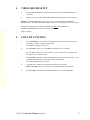
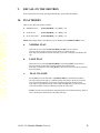
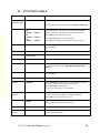
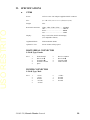
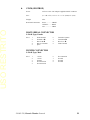
USO RESTRITO 12843 Foothill Blvd. Suite C Sylmar, California 91342 V: 818.898.3380 F: 818.898.3360 [email protected] Model No. 2034CL-TO (&2034CL-TO-T) 300 CLIP INSTANT ACCESS SYSTEM Pinnacle Thunder Odetics Protocol NOTE: Supports up to 4 Video Server Channels USER MANUAL 2034CL-TO, Pinnacle Thunder Protocol 1 USO RESTRITO Table of Contents 1. REVISION HISTORY GETTING STARTED . . .. 2. 3. 4. 5. 6. 7. 8. 9. 10. 11. 12. 13. SYSTEM DESCRIPTION DEFINITIONS SYSTEM INSTALLATION A. SHOTBOX B. ST300-S/SM, VTR/DDR CONTROLLER VIDEO SERVER SETUP CLIP LIST FUNCTION LEARN ON THE ST300 LEARN ON THE SHOTBOX RECALL ON THE ST300 RECALL ON THE SHOTBOX PLAY MODES A. NORMAL PLAY B. LOOP PLAY C. PLAY-TO-LOOP PLAY SINGLE CLIP IN LOOP OR PLAY-TO-LOOP MODES LEARN PLAY-TO-LOOP INTO CUE POINT A. ON THE ST300 B. ON THE SHOTBOX THE RECUE FUNCTION 4 5 5 5 6 6 6 7 7 8 8 8 9 9 9 9 9 10 10 10 10 11 ADVANCED FEATURES . . . 12 14. 15. 12 12 12 13 13 13 13 14 14 14 15 15 15 16 16 16 16. 17. 18. 19. 20. CREATING A CLIP CAPTURE FUNCTION A. SET AN IN (OUT) POINT B. VIEW THE IN (OUT) POINT C. CLEAR THE IN (OUT) POINT D. ENTER PREROLL VALUE E. EXECUTE CAPTURE FUNCTION SHOTBOX SHOTKEY MAPPING TO SHOTLIST LOCATIONS VIEW CONTENT OF CUE POINTS SHOTBOX CONTROL SWITCHES TRANSFERRING CUELIST A. TO TRANSMIT CUE POINTS TO THE ST300 B. TO TRANSMIT CUE POINTS TO THE PC RECEIVE CUELIST FUNCTION A. TO RECEIVE CUE POINTS FROM TH ST300 B. TO RECEIVE CUE POINTS FROM THE PC 2034CL-TO, Pinnacle Thunder Protocol 2 USO RESTRITO REFERENCE . . . 17 21. 22. 23. 17 19 20 20 20 20 21 21 21 22 22 23 24 24. 25. 26. SETUP MENU FUNCTION TABLE SPECIFICATIONS A. ST300 RS422 SERIAL CONNECTOR POWER CONNECTOR B. ST420 (SHOTBOX) RS422 SERIAL CONNECTOR POWER CONNECTOR TROUBLESHOOTING ST420 TROUBLESHOOTING KEY LAYOUT DNF CONTROLS LIMITED WARRANTY NOTE: For DNF software with a date code of 12/07/02 or later, please ensure that you have previously installed Pinnacle’s latest Thunder software and an updated THUNDER DLL file. Do not install the DNF eprom until the appropriate Thunder software has been installed. The Thunder Software Version installed should be Pinnacle Version 5.2 or any subsequent version issued by Pinnacle. If you do not have the appropriate version of Thunder software installed, or have any questions relating to your Thunder software, please contact Pinnacle. Manual Version............................……............................... 1.6 020604 Document ID....................……...................... 2034CL-TO User Manual 2034CL-TO, Pinnacle Thunder Protocol 3 USO RESTRITO 1. REVISION HISTORY 121702 Rev. 1.3 Added Thunder software version note. 092403 Rev. 1.4 Company header information revised. 110403 Rev. 1.5 Added DNF Controls Limited Warranty. Updated Receive Cue List & Transmit Cue List Function description. 020604 Rev. 1.6 Added note to Cover and Systems Description: Supports up to 4 Video Server Channels. 2034CL-TO, Pinnacle Thunder Protocol 4 USO RESTRITO Getting Started . . .. 2. SYSTEM DESCRIPTION The 300 Clip Instant Access System consists of the ST300-SSM VTR Controller, ST420 SHOTBOX and Shotlist Software. The ST300 controls up to 4 video channels individually or ganged. The SHOTLIST contains up to 300 CLIP IDs, stored in non-volatile memory in the ST300. Remotely view the CLIP IDs that exist in the Pinnacle Thunder under control. Desired clips can be MARKed into the SHOTLIST, at a single location or at multiple locations. Any clip in the SHOTLIST can be quickly loaded by simply entering the associated 3-digit number of its location, then pressing [LOAD]. Press [PLAY] to play the clip. Press [RECUE] to recue to the beginning of the clip. DEFINITIONS Throughout this manual, the Pinnacle Thunder will be referred to as “Video Server.” The ST300-S/SM as the ST300. The ST420 SHOTBOX is referred to as “SHOTBOX.” SHOTKEY refers to the 1-30 switches on the SHOTBOX Words surrounded by brackets, for example, [ENTER], are keys on the ST300 or the SHOTBOX. [XXX] + [XXX] means hold the two keys down simultaneously. 2034CL-TO, Pinnacle Thunder Protocol 5 USO RESTRITO 3. SYSTEM INSTALLATION a. b. SHOTBOX 1) Plug one end of a standard 9-pin, RS422 serial cable, into the OUTPUT connector on the rear of the SHOTBOX. Plug the other end of the cable into the AUX connector on the rear of the ST300. 2) Connect the 5 VDC, 1Amp POWER SUPPLY into the POWER connector on the rear of the SHOTBOX. Plug the Power Supply into an outlet, 90 VAC-240 VAC. ST300-S/SM, VTR/DDR CONTROLLER 1) Plug one end of a 9-conductor, RS422 serial cable into the VTR 1 (2, 3 or 4) connector on the rear of the ST300. Plug the other end of the cable into the 9pin REMOTE connector on the Video Server. 2) Connect the +5, +12, -12 VDC POWER SUPPLY into the POWER connector on the rear of the ST300. Plug the Power Supply into an outlet, 90 VAC to 240 VAC. 3) Check SETUP MENU prior to using the ST300 to confirm proper Record mode and other User settable modes. CONNECTION DIAGRAM 2034CL-TO, Pinnacle Thunder Protocol 6 USO RESTRITO 4. VIDEO SERVER SETUP a. Select ODETICS Broadcast communications protocol on the VIDEO SERVER to be controlled. b. Assign a serial port on the VIDEO SERVER through which the ST300 will control it. NOTES: The VIDEO SERVER may not support LTC or VITC time modes in ODETICS Broadcast mode. The ST300 will default to Tape Time if a non-supported time mode is selected. In Odetics Broadcast mode, the VIDEO SERVER may ONLY allow Full Record. INSERT and ASSEMBLE record modes may be disabled. Setup is complete. 5. CLIP LIST FUNCTION a. Press [CLIP LIST] to view the list of CLIP IDs that are resident on the Video Server. The display will show “CREATE NEW CLIP.” The CLIP LIST indicator will turn on. b. Press [LOAD] to create a new clip OR turn the Wheel to view CLIP IDs. Turn the Wheel clockwise to scroll forward, or counter-clockwise to scroll backward, through the list of available CLIPs. c. Press [LOAD] to load the current CLIP ID (shown on the top line of the display). After loading the selected clip, the CLIP LIST function will terminate. The CLIP LIST indicator will turn off. d. CLIP IDs can be manually entered from the ST300 numeric keypad OR the SHOTBOX “qwerty” keyboard: Enter an ID (maximum of 8 characters.) e. Press [LOAD] to load the entered CLIP ID and NOT save it in the SHOTLIST. 2034CL-TO, Pinnacle Thunder Protocol 7 USO RESTRITO 6. LEARN ON THE ST300 a. Select a VTR by pressing VTR [1], VTR [2], VTR [3] or VTR [4]. b. LOAD a Clip. If LEARNING a Gang, load all clips and set the Gang. c. Select the desired Cue Point by pressing [NEXT CUE], [LAST CUE], or by manually entering the Cue Point using the numeric keypad. The selected Cue Point number is shown on the bottom line of the display. d. Press [SHIFT] + [MARK] to initiate the LEARN. The display will show: Press VTR: MARK-Lrn 7. ESC-Cancel e. Press the VTR key desired: [1],[2],[3],[4]. f. Press [MARK] and the ST300 will: LEARN (save) the VTR Number (1,2,3,4), loaded CLIP ID and current IN/OUT time to the selected Cue Point. LEARN ON THE SHOTBOX a. Press [LEARN]. The LEARN indicator will turn on. b. Select the BANK [0] – [9] and then the desired Shotkey. c. The Learned CLIP ID will be displayed on the pressed key. NOTE: This will overwrite what you have assigned to the key previously. d. Press [LEARN] to exit at any time. NOTE: The [LEARN] key toggles LEARN mode on/off. 8. RECALL ON THE ST300 a. Select the desired Cue Point by pressing [NEXT CUE], [LAST CUE], or by manually entering the Cue Point using the numeric keypad. The selected Cue Point number is shown on the bottom line of the display. b. Press [LOAD] on the ST300. The ST300 will automatically load the Learned clips on the Learned VTRs, cue the clips to the Learned time, then set the Learned GANG mode. 2034CL-TO, Pinnacle Thunder Protocol 8 USO RESTRITO 9. RECALL ON THE SHOTBOX Select the desired Cue Point by pressing the BANK [0] – [9] and then the ShotKey. 10. PLAY MODES There are now three play modes available: NORMAL PLAY [LOOP ENABLE] = off [PTL] = off LOOP PLAY [LOOP ENABLE] = on [PTL] = off PLAY-TO-LOOP [LOOP ENABLE] = on [PTL] = on NOTE: All transport modes, other than PLAY, are disabled when [LOOP ENABLE] is ON. a. NORMAL PLAY This mode is active when [LOOP ENABLE] and [PTL] are not selected. The clip will play from its present location to the OUT point and stop. If the clip is beyond the OUT point when play is pressed, it will play to the END of the clip. b. LOOP PLAY This mode is active when [LOOP ENABLE] is selected and [PTL] is not selected. The clip will play in an infinite loop between the IN and OUT points. If the clip is outside the LOOP when [PLAY] is pressed it will CUE to the IN point and then start playing. c. PLAY-TO-LOOP Select [PTL] to activate this mode. ([LOOP ENABLE] is automatically enabled.) The clip will play from where it is parked (usually at the start) to the OUT point, then CUE to the IN point and play in an infinite loop between the IN and OUT points. If the clip is beyond the OUT point of the LOOP when [PLAY] is pressed, it will first CUE to the START of the clip and then go into PLAY-TO-LOOP. NOTE: If no IN point is marked, the default IN point is the START of the clip, and if no OUT is marked, the default OUT is the END of the clip. 2034CL-TO, Pinnacle Thunder Protocol 9 USO RESTRITO 11. PLAY SINGLE CLIP IN LOOP OR PLAY-TO-LOOP MODES a. LOAD the clip. (The clip MUST be loaded from the DNF Controller.) b. Set the IN and OUT points. (See page Section 13, CAPTURE FUNCTION.) c. Press [PTL] or [LOOP ENABLE]. d. Hold [SHIFT] and press [RECUE]. e. Enter the starting point of the LOOP or PTL, press [ENTER]. f. Press [PLAY]. g. To clear the IN or OUT points, hold [DEL] and press [IN] or [OUT]. 12. LEARN PLAY-TO-LOOP INTO CUE POINT Follow steps a and b above to LOAD a clip and set the IN and OUT points; press [PTL]. a. b. ON THE ST300 1) Select a Cue Point by pressing [LAST CUE], [NEXT CUE] or by entering the 3-digit number using the numeric keypad, then pressing [ENTER]. 2) Press [SHIFT] + [MARK]. 3) Press the VTR number you wish to learn the Cue Point into. 4) Press [MARK]. ON THE SHOTBOX 1) Recall the Cue Point that has been LEARNED as a PTL. 2) Select the Bank in which you wish to store the clip. 3) Press [LEARN] on the SHOTBOX. 4) Press the desired ShotKey. (The name of the clip will be displayed on the SHOTBOX with a ‘#’ sign before its name, indicating that the clip was saved as a PTL.) 2034CL-TO, Pinnacle Thunder Protocol 10 USO RESTRITO 13. THE RECUE FUNCTION If the IN or OUT time is being displayed, the clip will RECUE to the displayed IN or OUT time. If the IN or OUT time is not displayed, the clip will RECUE to the start of the clip. NOTES: • All transport modes, other than PLAY, are disabled when [LOOP ENABLE] is ON. • When saving a Cue Point and no IN point is set, the current clip location will be used as the IN point. • There MUST be at least 4 seconds between the IN and OUT points for any LOOP COMMAND. 2034CL-TO, Pinnacle Thunder Protocol 11 USO RESTRITO Advanced Features . . . 14. CREATING A CLIP a. Press [CLIP LIST]. The CLIP LIST indicator will turn on. The display will show “CREATE NEW CLIP.” b. Press [LOAD]. The display will show the default CLIP ID. c. Press [LOAD] to accept the default CLIP ID. OR Use [NEXT CUE], [LAST CUE] and Wheel to edit the CLIP ID. Use the [NEXT CUE] and [LAST CUE] keys to position the cursor. Turn the Wheel to select the desired letter. OR Enter a name with a maximum of 8 characters on the SHOTBOX keyboard. NOTE: On the SHOTBOX, for numbers, use bank keys 0-9, with “0” being 10. d. Press [LOAD] on the ST300 or on the SHOTBOX to create the selected CLIP ID. e. If the selected CLIP ID already exists, a warning message will be displayed. To load the existing clip, press [ENTER]. Press [ESC] to exit without loading the existing clip. 15. CAPTURE FUNCTION The CAPTURE function allows source material from a VTR to be recorded into the Video Server. A CLIP ID is also created. VTR1 is always the Recorder (the Video Server). Select VTR [2], [3] or [4], as the source VTR. Any RS422, SONY protocol compatible VTR can be used. Use the transport function keys to control the source VTR. Each source VTR has its own set of IN and OUT points. a. SET AN IN (OUT) POINT 1) Shuttle to the location and press [IN] ([OUT]) to set the IN (OUT) Point. The IN (OUT) indicator on the ST300 will turn on. OR Press [SHIFT] + [IN] ([OUT]) to manually enter a new IN time. 2) Press [ENTER] to save the entered time. OR Press [ESC] to exit without saving. 2034CL-TO, Pinnacle Thunder Protocol 12 USO RESTRITO b. VIEW THE IN (OUT) POINT 1) When the IN (OUT) indicator is on, press [IN] ([OUT]) to view the existing IN (OUT) Point. 2) While viewing the IN (OUT) Point: Press [MARK] to overwrite the saved time with the current time. Press [RECUE] to search to the IN (OUT) point. c. d. CLEAR THE IN (OUT) POINT 1) Press and hold [DEL]. 2) Press and release [IN] ([OUT]). The IN (OUT) indicator will turn off. ENTER PREROLL VALUE 1) Press [MENU] and turn the Wheel until “Enter PREROLL:” is shown. 2) Enter the desired preroll value using the ST300’s numeric keypad. 3) Press [ENTER] to save the entered value. OR Press [ESC] to exit without saving. e. EXECUTE CAPTURE FUNCTION 1) Press VTR[2], VTR[3] or VTR[4] to select the source VTR. 2) Press [SHIFT] + [RECORD]. The display will prompt you for a CLIP ID. A default CLIP ID will be shown. 3) Press [LOAD] to accept the default CLIP ID. OR Use [NEXT CUE], [LAST CUE] and Wheel to edit the CLIP ID. 4) Press [LOAD] to accept the CLIP ID. The ST300 will create the new CLIP ID on the Video Server. The Source VTR will preroll to the IN Point, then play. At the Source VTR’s IN point, the RECORDER will go into record. At the Source VTR’s OUT point, the RECORDER will stop record, post-roll for 2 seconds, then stop. The Source VTR will search to the OUT point and stop. The OUT point will be cleared. The IN indicator will stay on. The OUT indicator will turn off. 2034CL-TO, Pinnacle Thunder Protocol 13 USO RESTRITO 16. SHOTBOX SHOTKEY MAPPING TO SHOTLIST LOCATIONS The SWITCHES on the SHOTBOX access the SHOTLIST locations as follows: BANK 0, SWITCHES 1 Æ 30 access SHOTLIST locations 001 Æ 030. BANK 1, SWITCHES 1 Æ 30 access SHOTLIST locations 101 Æ 130. BANK 2, SWITCHES 1 Æ 30 access SHOTLIST locations 201 Æ 230. BANK 3, SWITCHES 1 Æ 30 access SHOTLIST locations 301 Æ 330. BANK 4, SWITCHES 1 Æ 50 access SHOTLIST locations 401 Æ 430. BANK 5, SWITCHES 1 Æ 30 access SHOTLIST locations 501 Æ 530. BANK 6, SWITCHES 1 Æ 30 access SHOTLIST locations 601 Æ 630. BANK 7, SWITCHES 1 Æ 30 access SHOTLIST locations 701 Æ 730. BANK 8, SWITCHES 1 Æ 30 access SHOTLIST locations 801 Æ 830. BANK 9, SWITCHES 1 Æ 30 access SHOTLIST locations 901 Æ 930. 17. VIEW CONTENT OF CUE POINTS a. Press [VIEW]. The VIEW indicator comes on. b. Press the switch for which you would like to see the content. c. The switch turns RED and the content (CLIP ID) of the corresponding Cue Point is displayed on a virtual display. For Example: VTR 1 Clip 23 VTR 2 Clip 13 VTR 3 Clip 77 VTR 4 No Assignment NOTE: All the remaining switches are not illuminated. d. Release the keys to return to normal operation. 18. SHOTBOX CONTROL SWITCHES a. [PLAY]: Plays out the selected clip. b. [RECUE]: Returns to the beginning of the clip. c. [STOP]: Stops playout of the clip. 2034CL-TO, Pinnacle Thunder Protocol 14 USO RESTRITO 19. TRANSFERRING CUELIST The TRANSMIT CUELIST function allows you to transmit your list of Cue Points to a PC, using the provided utility software on the PC, or to another ST300. Transfer to a PC requires OpSuite 3.0 software, which runs on a Windows-based computer. Contact DNF Controls for more information. a. TO TRANSMIT CUE POINTS TO THE ST300 1) Connect the VTR4 connector on the rear of the ST300 to the VTR4 connector of the receiving ST300 using an RS422 9-pin cable with TX and RX lines crossed. (A “turnaround” cable) 2) Press [MENU] and scroll the Wheel to “Transmit CUE List? YES=Enter, Exit=ESC” 3) Press [ENTER] to start transmitting. The Display shows “Waiting to transmit” on the first line. 4) When the Receiver is ready, transfer starts automatically. The Display now shows “Transmitting cuelist.” 5. After the transfer is over the display shows “Transfer is over” for one second, then shows “Waiting to transmit” again. 6) Connect another ST300 to transmit the list again. OR Press [ESC] twice to exit. b. TO TRANSMIT CUE POINTS TO THE PC 1) Connect the VTR4 connector on the back of the ST300 to one of the COM ports on the PC using an RS422 to RS232 adapter. 2) Repeat steps 1-6 of the TO TRANSMIT CUE POINTS TO THE ST300 section. 2034CL-TO, Pinnacle Thunder Protocol 15 USO RESTRITO 20. RECEIVE CUELIST FUNCTION The RECEIVE CUELIST function allows you to receive your list of Cue Points from a PC or from another ST300. Transfer to a PC requires OpSuite 3.0 software, which runs on a Windowsbased computer. Contact DNF Controls for more information. a. b. TO RECEIVE CUE POINTS FROM TH ST300 1) Connect the VTR4 connector on the back of the ST300 from the VTR4 connector of the transmitting ST300 using RS422 9-pin cable with TX and RX lines crossed. (A “Turnaround” Cable) 2) Press [MENU] and scroll the Wheel to “Receive CUE List? YES=Enter, Exit=ESC” 3) Press [ENTER] to start receiving. The Display shows “Waiting to receive” on the first line. 4) When the Transmitter is ready, transfer starts automatically. The Display now shows “Receiving cuelist.” 5) After the transfer is over the display shows “Done-Success! Press any key…” 6) Press any key. The display shows “Receive cuelist?” message. 7) Press [ESC] to exit the MENU mode. TO RECEIVE CUE POINTS FROM THE PC 1) Connect the VTR4 connector on the back of the ST300 to one of the COM ports on the PC using RS422 to RS232 adapter 2) Repeat steps 2-7 of TO RECEIVE CUE POINTS FROM THE ST300 section. 2034CL-TO, Pinnacle Thunder Protocol 16 USO RESTRITO Reference . . . 21. SETUP MENU Press [MENU]. The MENU indicator turns on. Turn the Wheel to select item to change. Press [MENU] OR use the Softkeys to change the desired mode for that option. Turn the Wheel at anytime to select another item. Press [ESC] at anytime to exit SETUP MENU. The MENU indicator turns off. (Turning Wheel Clockwise) MENU MODES RECORD Press [MENU] to select the desired record mode: Lockout, Assemble, Crash (Full) or Insert. Only in INSERT mode: Press the associated Softkey, located below the display, to toggle Video(V), Audio1(A1), Audio2(A2), Audio3(A3), Audio4(A4) on/off. WIND MODE Press Softkey to select: HOLD (Fast wind is maintained only while key is depressed.) OR LATCH (Fast wind is initiated and maintained with momentary key press.) Select fast wind speed (3.9 to 23.7) by pressing Softkey below SPD. SLOMO ST300 display shows: SLOMO with: TBAR WHEEL Speed Prset Press Softkey [TBAR] (or [WHEEL]) to toggle between them. The T-BAR has a speed range of 0 Æ +200 with a detent at +100 % play speed OR a range of 0 Æ +100 (detent at +100 % play speed). For Wheel only: Press Softkey [SPEED] to select SLOMO speed ranges: Press Softkey to select: 0 Æ +200 OR -100 Æ +200. Press Softkey [BACK] to return to SLOMO MENU. Press [ESC] to exit MENU OR turn the Wheel to select another item. For Wheel only: Press Softkey [PRSET] to select the SLOMO Preset Speed Mode. Press Softkey [UPDATE]. When exiting SLOMO mode, the last used speed is saved in the Preset Speed register. Press Softkey [STATIC]. The Preset Speed register is NOT updated when exiting SLOMO mode. It is only changed by [SHIFT] + [SLOMO] (PRESET SLOMO). 2034CL-TO, Pinnacle Thunder Protocol 17 USO RESTRITO ST300 SETUP ST300 SETUP Clear Cues S D f l Press Softkey beneath ClearCues to clear all Cue Points to 00:00:00:00. Press Softkey [YES] when asked “Are You Sure?” Press Softkey beneath SetDefault to set ST300 to default settings. Press Softkey [YES] when asked “Are You Sure?” DISPLAY SOFTWARE VERSION The version number for the currently installed software is displayed. SHOTBOX ON/OFF Enables use of Shotbox. RECORD Press Softkey to select single button or 2-button record. RECORD = [REC] Only OR [REC] + [PLAY]. PREROLL Enter Preroll value. TRANSMIT CUELIST Transmits Cuelist to another ST300 or to a PC. RECEIVE CUELIST Receives Cuelist from another ST300 or a PC. 2034CL-TO, Pinnacle Thunder Protocol 18 USO RESTRITO 22. FUNCTION TABLE Function Key Press Description GOTO ENTERED TIME [SHIFT] + [RECUE] Search the VTR to the manually entered time. Use the ST300 numeric keypad. Press [ENTER] or [RECUE]. GANG [SHIFT] + [VTR#1] OR [SHIFT] + [VTR#2] OR [SHIFT] + [VTR#3] OR [SHIFT] + [VTR#4] Individually press the VTR keys to be included in the gang. The LED above the key will turn on. Press the VTR key again to remove from gang. The LED above the key will turn off. Press [ESC] to exit and save the gang. FFWD [FFWD] Press and HOLD to shuttle. Release key to stop. Set WIND Speed in MENU. JOG [JOG] Select JOG mode and enable Wheel. LAST CUE [LAST CUE] Step to the previous Cue Point Location. NEXT CUE [NEXT CUE] Step to the next Cue Point Location. RECORD [REC] Places VTR into the Record mode selected by RECORD MODE in the SETUP MENU. Press [RECORD] OR [RECORD] + [PLAY]. REWIND [RWD] Press and HOLD to shuttle. Release key to stop. Set WIND Speed in MENU. SHUTTLE [SHUTTLE] Select SHUTTLE mode and enable Wheel. SLOMO [SLOMO] Press [SLOMO] to slo-mo the VTR. Turn the Wheel (or move the T-Bar, if available) to change the play speed. Press [SLOMO] to STILL frame or press any transport key to exit SLOMO. SLO-MO SPEED PRESET [SHIFT] + [SLOMO] For WHEEL ONLY: Press [SHIFT] + [SLOMO] to preset the slo-mo speed. Turn the Wheel to select desired speed. Press [ESC] or any transport key to exit. STOP [STOP] Press once to STILL frame VTR. Press again to put VTR into STOP mode. LOOP [SHIFT] + [PLAY] Plays the currently loaded clip in a continuous loop. TIME MODE SELECT [TIME MODE] Press to toggle between Timecode (TC), VITC (VT) or Tape Timer (TM) display modes. The VTR LEDs that are on show the gang. The flashing LED shows which VTR is currently selected. 2034CL-TO, Pinnacle Thunder Protocol 19 USO RESTRITO 23. SPECIFICATIONS a. ST300 Power: 90 VAC to 265 VAC adapter supplied with IEC connector Size: (L” x W” x H”) 12” x 6” x 1.5” (front) 3.0” (rear) Weight: 4 lbs. Rear Panel Connectors: VTR1, VTR2, VTR3, VTR4......... All DB9F GPI................................................. DBF15F Power............................................. DB9M Aux ................................................ DB9F Display: Easy to read 2-line, back-lit LCD display (User adjustable contrast) Jog/Shuttle Wheel: With mechanical detents. Optional “T”-bar: Slo-mo 0-200% of Play Speed RS422 SERIAL CONNECTOR 9-Pin D-Type, Female Pin # 1 2 3 4 5 Frame Ground Receive A Í Transmit B Î Transmit Common Spare 6 7 8 9 Receive Common Receive B Í Transmit A Î Frame Ground 6 7 8 9 +5 VDC Ground Ground Ground POWER CONNECTOR 9-Pin D-Type, Male Pin # 1 2 3 4 5 +5v DC +5v DC Ground +12 VDC –12 VDC 2034CL-TO, Pinnacle Thunder Protocol 20 USO RESTRITO b. ST420 (SHOTBOX) Power 90 VAC to 265 VAC adapter supplied with IEC connector Size: (L” x W” x H”) 11.5” x 6 .5” x 1.75” (front) 3.5” (rear) Weight: 4 lbs. Rear Panel Connectors: Power ..........…. DB9M OUTPUT ......... DB9F Aux .................. DB9F RS422 SERIAL CONNECTOR 9-Pin D-Type, Female Pin # 1 2 3 4 5 Frame Ground Transmit A Î Receive B Í Receive Common Spare 6 7 8 9 Transmit Common Transmit B Î Receive A Í Frame Ground 6 7 8 9 No Connection Ground Ground Ground POWER CONNECTOR 9-Pin D-Type, Male Pin # 1 2 3 4 5 +5v DC +5v DC Ground No Connection No Connection 2034CL-TO, Pinnacle Thunder Protocol 21 USO RESTRITO 24. TROUBLESHOOTING ST420 TROUBLESHOOTING a. All Shotkeys are RED - no communication with ST300. b. All Shotkeys are dark - No communication between the ST300 and the Video Server. c. The version of the ST420 must comply in the software version with the ST300 it is connected to. To determine the software version of the ST420 do the following: 1) Press [SHIFT] + [STOP] + [PLAY]. The Shotkey that displays the current version is RED. 2) The ST420 displays: “SELECT ST300 V2.1 or V2.0 or V 3.0” Press the Shotkey that matches the software version of ST300 being used. To determine the ST300’s version, press [MENU] and turn the Wheel to the display that shows the current software. 2034CL-TO, Pinnacle Thunder Protocol 22 USO RESTRITO 25. KEY LAYOUT 2034CL-TO, Pinnacle Thunder Protocol 23 USO RESTRITO 26. DNF CONTROLS LIMITED WARRANTY DNF Controls warrants its product to be free from defects in material and workmanship for a period of one (1) year from the date of sale to the original purchaser from DNF Controls. In order to enforce the rights under this warranty, the customer must first contact DNF’s Customer Support Department to afford the opportunity of identifying and fixing the problem without sending the unit in for repair. If DNF’s Customer Support Department cannot fix the problem, the customer will be issued a Returned Merchandise Authorization number (RMA). The customer will then ship the defective product prepaid to DNF Controls with the RMA number clearly indicated on the customer’s shipping document. The merchandise is to be shipped to: DNF Controls 12843 Foothill Blvd., Suite C Sylmar, CA 91342 USA Failure to obtain a proper RMA number prior to returning the product may result in the return not being accepted, or in a charge for the required repair. DNF Controls, at its option, will repair or replace the defective unit. DNF Controls will return the unit prepaid to the customer. The method of shipment is at the discretion of DNF Controls, principally UPS Ground for shipments within the United States of America. Shipments to international customers will be sent via air. Should a customer require the product to be returned in a more expeditious manner, the return shipment will be billed to their freight account. This warranty will be considered null and void if accident, misuse, abuse, improper line voltage, fire, water, lightning or other acts of God damaged the product. All repair parts are to be supplied by DNF Controls, either directly or through its authorized dealer network. Similarly, any repair work not performed by either DNF Controls or its authorized dealer may void the warranty. After the warranty period has expired, DNF Controls offers repair services at prices listed in the DNF Controls Price List. DNF Controls reserves the right to refuse repair of any unit outside the warranty period that is deemed non-repairable. DNF Controls shall not be liable for direct, indirect, incidental, consequential or other types of damage resulting from the use of the product. ### 2034CL-TO, Pinnacle Thunder Protocol 24