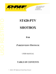
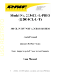
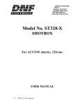
1
12843 Foothill Blvd.,
Suite D
Sylmar, CA 91342
818 898 3380 voice
818 898 3360 fax
[email protected]
www.dnfcontrols.com
ST420-VSS Shotbox
for
Vista Systems Spyder
User Manual
Revision 1.03
TABLE OF CONTENTS
REVISIONS ..........................................................................................................2
1.
OVERVIEW ...................................................................................................3
2.
COMPONENT LIST.......................................................................................4
3.
INSTALLATION .............................................................................................4
4.
CONNECTION DIAGRAM .............................................................................5
5.
SETUP...........................................................................................................6
6.
OPERATION................................................................................................12
7.
SPECIFICATIONS.......................................................................................19
8.
KEYBOARD LAYOUT..................................................................................20
9.
DNF CONTROLS LIMITED WARRANTY ....................................................21
REVISIONS
1.00
1.01
1.02
1.03
11/13/06
12/12/06
12/20/06
01/04/07
Page 2 of 21
Original draft.
First preliminary manual.
Add Learn Script function.
Updated Learn function.
ST420-VSS User Manual
1.
OVERVIEW
The ST420-VSS Shotbox provides a fast and easy means to recall Command
Keys on Spyder. The Shotbox is typically used in lieu of Vista’s control panel. It
may be used in conjunction with a computer or without a computer. The Shotbox
connects to Spyder over an ethernet interface.
The ST420-VSS Shotbox gives you the power to:
•
Read Commands Keys from Vista Advanced and automatically map to
Shotbox keys
•
Assign Command Key to a specific Shotbox key
•
Recall a Command Key at the press of a key
•
Recall a Group of Command Keys at the press of a key
•
Step forward and backwards through the cues in a single Script or a group of
Scripts
•
Jump to a specific cue in a Script or to another Command Key and cue.
•
Jump to the PREVIEW or PROGRAM cue at the press of a key.
•
Assign up to 270 Command Keys- 10 banks x 27 keys per bank
ST420-VSS User Manual
Page 3 of 21
2.
3.
COMPONENT LIST
Qty Component
DNF Part Number
1
ST420 SHOTBOX
ST420-VSS
1
ST420 POWER SUPPLY
1025-0003-00
1
POWER CORD
part of above
1
LANTRONIX UDS 1100 ADAPTOR 1585-0100-00
1
LANTRONIX POWER SUPPLY
part of above
1
D9F-D25M CABLE
part of above
1
DB9 M-M GENDER CHANGER
1030-0100-00
INSTALLATION
a. Attach mini DB9 M-M gender changer to the OUTPUT connector on the
rear of the ST420. Turn the hex end of the jack screws to fasten the
adaptor to the ST420.
b. Connect the D9F end of the furnished cable to the DB9 M-M gender
changer.
c. Connect the other end (D25M) of the furnished cable to the LANTRONIX
adaptor.
d. Connect one end of an Ethernet cable to the LANTRONIX adaptor.
e. Connect the other end of the Ethernet cable to the same ethernet
hub/switch that Spyder is connected to.
f.
Connect the LANTRONIX power supply to the power input connector on the
LANTRONIX.
g. Connect the power supply to an AC outlet.
h. Connect the ST420 power supply to the POWER connector on the rear of
the ST420.
i.
Connect the IEC connector end of the power cable into the ST420 POWER
SUPPLY.
j.
Connect the other end of the power cable into an AC outlet.
Page 4 of 21
ST420-VSS User Manual
4.
CONNECTION DIAGRAM
ST420-VSS User Manual
Page 5 of 21
5.
SETUP
Press the [SHIFT] + [ENTER] keys to enter the Setup Menu. Press the [ESC]
key at any time to exit the Setup Menu.
a) Press the [SET UP LANTRONIX] key (shotkey #13) to configure the serial
to Ethernet adaptor.
Disconnect the power connector to the adaptor and reconnect it. Within
three seconds, press any key on the Shotbox. The diagnostic LED on the
LANTRONIX adaptor will flash RED. The Shotbox keys will display VIEW
IP ADDRESS, VIEW SUBNET MASK, VIEW GATEWAY, and VIEW
SPYDER IP ADDRESS
b) Set IP Address
1) Press the [VIEW IP ADDRESS] key (shotkey #1). The IP address
is displayed in four keys in the upper right section of the keyboard.
The key with green illumination is the active field. Use the [<<<<}
or [>>>>] keys to select the field that you want to change.
2) Enter the IP address of the adaptor using the displayed numeric
keypad on the Shotbox. This has to be a unique address that is not
used by any other device on the network.
3) Press the [ENTER] key to save the entered IP address.
OR
Press the [ESC] key or [BACK] key (shotkey #30) to exit without
saving changes.
Page 6 of 21
ST420-VSS User Manual
c) Set Subnet Mask
1) Press the [VIEW SUBNET MASK] key (shotkey #2). The Subnet
Mask is displayed in four keys in the upper right section of the
keyboard. The key with green illumination is the active field. Use
the [<<<<} or [>>>>] keys to select the field that you want to
change.
2) Enter the Subnet Mask for the IP address entered in #B above
using the displayed numeric keypad on the Shotbox. (For example,
enter 255.255.255.0 for a Class C IP address). If not sure, enter
255.255.255.0.
3) Press the [ENTER] key to save the entered Subnet Mask.
OR
Press the [ESC] key or [BACK] key (shotkey #30) to exit without
saving changes.
d) Set Gateway
1) Press the [VIEW GATEWAY] key (shotkey #3). The Gateway IP
Address is displayed in four keys in the upper right section of the
keyboard. The key with green illumination is the active field. Use
the [<<<<} or [>>>>] keys to select the field that you want to
change.
2) Enter the Gateway IP address using the displayed numeric keypad
on the Shotbox. If the Spyder and Shotbox are connected to the
same ethernet hub or switch, enter 0.0.0.0.
3) Press the [ENTER] key to save the entered Gateway address.
OR
Press the [ESC] key or [BACK] key (shotkey #30) to exit without
saving changes.
ST420-VSS User Manual
Page 7 of 21
e) Set Spyder IP Address
1) Press the [VIEW SPYDER IP ADR] key (shotkey #4). The Spyder
IP Address is displayed in four keys in the upper right section of the
keyboard. The key with green illumination is the active field. Use
the [<<<<} or [>>>>] keys to select the field that you want to
change.
2) Enter the IP address assigned to the Spyder that Shotbox will
control. Use the displayed numeric keypad on the Shotbox.
3) Press the [ENTER] key to save the entered Spyder IP Address.
OR
Press the [ESC] key or [BACK] key (shotkey #30) to exit without
saving changes.
f) Save LANTRONIX Configuration
1) Press the [SAVE] key (shotkey #21).
2) The LANTRONIX configuration will be saved in non-volatile
memory inside the LANTRONIX adaptor. This must be done for
any configuration changes to take affect. The diagnostic LED on
the LANTRONIX adaptor will turn off.
Page 8 of 21
ST420-VSS User Manual
g) Set Spyder Status Polling Rate
This sets the rate at which the Shotbox gets status information from the
Spyder. The number that is displayed is in 10s of milliseconds. The
default polling rate is 50, which is equal to 500ms (milliseconds) or 0.5
seconds.
NOTE- It is recommended that the polling rate be left at the default
value of 50 (500ms).
1) Press the [POLLING RATE] key (shotkey #11).
2) The POLLING RATE is displayed in three keys in the upper right
section of the keyboard.
3) Enter the Polling Rate using the displayed numeric keypad on the
Shotbox.
4) Press the [ENTER] key to save the entered Polling Rate.
OR
Press the [ESC] key or [BACK] key (shotkey #30) to exit without
saving changes.
h) Toggle Spyder Status Polling ON/OFF
NOTE- It is recommended that the polling be set to ON.
1) The POLLING ON/OFF is displayed in the key. Each key press will
toggle the function.
2) Press the POLLING key until it shows "POLLING ON".
NOTE- After exiting the Setup Menu, the six control key LEDs—
SHIFT through ENTER – will turn on to indicate that there
is no communication between the Shotbox and Spyder.
The six control key LEDs will remain off while the Shotbox
successfully communicates with Spyder.
The six control key LEDs will NOT change state in the
Setup Menu.
ST420-VSS User Manual
Page 9 of 21
i) Learn option
NOTE: The switches that are read from the Spyder using the "Read CMD
Keys" button are always read as Command Keys regardless of this menu
setting. This menu setting applies only to manual learns.
Press to toggle between "LEARN: SCRIPT" or "LEARN: CMD KEY"
When set to "LEARN: SCRIPT", all the switches that are learned contain
SCRIPT information. The actual Page and Register number is not saved.
The command key can be moved to any page or moved within the page
but the content of the switch stays the same.
The first line of the switches shows an up to 5-digit script number when
"LEARN: SCRIPT" is selected.
When set to "LEARN: CMD KEY", all the switches that are learned
contain Page and Register number information. If the command is moved
to another page or within the page the content of the switch has to be relearned.
The first line of the switches shows a page number and a register number
separated by a space when "LEARN: CMD KEY" is selected.
Page 10 of 21
ST420-VSS User Manual
j) Set Default Cue (Used by Read Command Key)
The default cue number will be automatically assigned to all Shotbox keys
populated by the READ COMMAND KEY function (see below). A Shotbox
key press will load the selected Command Key and jump to this cue
number.
1) Press the [ENTER DEFAULT CUES] key (shotkey #2)
2) The DEFAULT CUE is displayed in upper right section of the
keyboard.
3) Enter the Default Cue number using the displayed numeric keypad
on the Shotbox. Enter 0 {zero} for PREVIEW or 1 for PROGRAM.
4) Press the [ENTER] key to save the entered default cue number.
OR
Press the [ESC] key or [BACK] key (shotkey #30) to exit without
saving changes.
k) Read Command Keys into Shotbox
Use the Read Command Keys function to read pre-defined Command
Keys in Vista Advanced and automatically assign them to Shotbox keys.
All Command Keys on page 1 will be assigned to Shotbox bank 1. All
Command Keys on pages 2, 3, 4, 5, 6, 7, 8 & 9 will be assigned to
Shotbox banks 2, 3, 4, 5, 6, 7, 8 & 9, respectively.
All Command Keys numbered 1 through 27, on a page, will be assigned to
Shotbox keys 1 through 27, respectively. All Command Keys numbered
greater than 27 will NOT be assigned to Shotbox keys.
1) Press the [READ CMD KEYS] key (shotkey #1). The key will turn
green.
Please wait for the Command Key data to be loaded into the
Shotbox. This process takes several seconds.
Upon completion, the Shotbox will automatically exit the Setup
Menu and display the Command Keys assigned to the currently
selected bank.
ST420-VSS User Manual
Page 11 of 21
6.
OPERATION
The Shotbox supports two major modes of operation— LEARN and RECALL.
After recalling a single or group of Command Keys, step forward or backwards
through each cue, or jump to a specific cue.
The Command Keys on pages 1 through 9 of Vista Advanced may be
downloaded into banks 1 through 9, respectively, on the Shotbox. The
Command Keys number 1 through 27 on each page will be downloaded into
Shotbox keys 1 through 27. See the “READ COMMAND KEYS” section in this
manual for more information. All operator LEARNs in these banks will be
overwritten.
Bank 0 on the Shotbox is reserved for Operator LEARNs. Any Command Key
on any page may be assigned to any Shotbox key. See the “LEARN
COMMAND KEY” section of this manual. Bank 0 assignments will not be
overwritten during a READ COMMAND KEYS download.
Bank 1 through Bank 9 will only allow the same Command Key number to be
assigned to a Shotbox key. For example, Command Key number 15 will be
assigned only to Shotbox key 15. The assigned cue number and text label
may be any value.
a) LEARN COMMAND KEY / SCRIPT
1. Press the LEARN key to initiate the Learn process.
The LEARN key led will turn on and the keyboard will turn yellow.
Press the LEARN key a second time to terminate LEARN at any time
prior to completing the Learn process. The LEARN key led will turn off.
2. Select a Shotbox BANK key. The BANK key led will turn on.
The Shotkeys will display all current LEARNs in the selected bank.
3. Select a Shotkey.
LEARN = CMD KEY
Overwrite an existing assignment or create a new assignment.
When the setting is set to "LEARN: CMD KEY", the user is prompted to enter
PAGE, REGISTER, CUE and LABEL.
4. Follow the displayed prompt on the Shotbox and enter a Page number,
1 – 20.
Enter a 1 or 2 digit number. Leading zeroes are not required.
Press the DELETE key to delete the last entered digit.
Press the ENTER key to complete the entry OR press the ESC key to
exit.
Page 12 of 21
ST420-VSS User Manual
5. Follow the displayed prompt on the Shotbox and enter a Register
(Command Key) number.
Enter a 1, 2, or 3 digit number. Leading zeroes are not required.
Press the DELETE key to delete the last entered digit.
Press the ENTER key to complete the entry OR press the BACK or
ESC key to exit.
6. Follow the displayed prompt on the Shotbox and enter a Cue number.
Enter a 1, 2, or 3 digit number. Leading zeroes are not required.
Press the DELETE key to delete the last entered digit.
Press the ENTER key to complete the entry OR press the BACK or
ESC key to exit.
7. Follow the displayed prompt on the Shotbox and enter a label of 1 to
12 characters.
Press the DELETE key to delete the last entered digit.
Press the ENTER key to complete the entry OR press the BACK or
ESC key to exit.
The Label, Page and Command Key number will be displayed on the face
of the Shotkey. Or Script and Label will be displayed depending on menu
setting.
LEARN = SCRIPT
Overwrite an existing assignment or create a new assignment.
When the setting is set to "LEARN: SCRIPT", the user is prompted to enter
SCRIPT, CUE and LABEL.
1. Follow the displayed prompt on the Shotbox
2. Enter a 1 - 5 digit SCRIPT number. Leading zeroes are not required.
Press the DELETE key to delete the last entered digit.
Press the ENTER key to complete the entry OR press the ESC key to
exit.
ST420-VSS User Manual
Page 13 of 21
3. Follow the displayed prompt on the Shotbox and enter a Cue number.
Enter a 1, 2, or 3 digit number. Leading zeroes are not required.
Press the DELETE key to delete the last entered digit.
Press the ENTER key to complete the entry OR press the BACK or
ESC key to exit.
4. Follow the displayed prompt on the Shotbox and enter a label of 1 to
12 characters.
Press the DELETE key to delete the last entered digit.
Press the ENTER key to complete the entry OR press the BACK or
ESC key to exit.
The Label, Cue and Script number will be displayed on the face of the
Shotkey. Or Script and Label will be displayed depending on menu
setting.
b) CLEAR LEARN
1. Press the desired BANK key.
2. Press and hold the SHIFT key.
3. Press the desired Shotbox key to be cleared. The face of the Shotbox
key will be blank.
c) RECALL COMMAND KEY
1. Press the desired BANK key.
The selected BANK key’s led will turn on. The Shotbox keys will
display all LEARNs in the selected bank.
2. Press the desired Shotbox key. The Shotbox key will turn RED.
The LEARN’d Command Key and Cue number will be immediately sent to
the Spyder for recall.
Page 14 of 21
ST420-VSS User Manual
d) GROUP RECALL
1. Press the GROUP key to recall more than one Command Key. The
GROUP key led will turn on.
Press the ESC key to terminate group recall. The GROUP key led will
turn off.
2. Press the desired BANK and Shotbox key. The key will turn RED to
indicate that it is selected as part of the group. Press the key again to
remove it from the group.
3. Repeat step 2 for each Bank/Shotbox key that will be part of the group.
The maximum size of the group is 10 keys.
4. Press the GROUP key to complete group selection and recall the
selected Command Keys. All keys that are part of the group will
remain RED.
e) SELECT COMMAND KEY
Select the Command Key that will be affected by the JUMP, REV, FWD,
and PVW/PGM keys.
1. Press the SELECT key. The SELECT key led will turn on.
2. Press the desired BANK key.
3. Press the desired Shotbox key. The face of the key will turn red. The
SELECT key led will turn off.
OR
Press the ESC key to exit select mode without any changes.
f) REV, FWD, PVW/PGM
1. Press the REV (<<<) or FWD (>>>) key to step forward or backward,
respectively, through the currently selected script (red Shotbox key) or
group of scripts.
When the last cue is reached, additional REV Key presses will be
ignored. When the first Cue is reached, additional FWD key presses
will be ignored.
2. Press the PVW/PGM key to jump to the PREVIEW cue of the currently
selected script or group of scripts.
3. Press the SHIFT + PVW/PGM keys to jump to the PROGRAM cue of
the currently selected script or group of scripts.
ST420-VSS User Manual
Page 15 of 21
g) JUMP TO CUE
LEARN = CMD KEY
1. Press the JUMP key to initiate the jump process.
2. Follow the displayed prompt on the Shotbox and enter the desired
cue.
Enter a 1, 2, or 3 digit number. Leading zeroes are not required.
Press the DELETE key to delete the last entered digit.
3. Press ENTER to jump to the entered cue.
OR
3. Press the JUMP TO REG key.
4. Follow the displayed prompt on the Shotbox and enter the desired
page number.
Enter a 1 or 2 digit number. Leading zeroes are not required.
Press the DELETE key to delete the last entered digit.
Press the ENTER key to complete the entry OR press the ESC key to
exit.
5. Follow the displayed prompt on the Shotbox and enter the desired
REGISTER number.
Enter a 1, 2 or 3 digit number. Leading zeroes are not required.
Press the DELETE key to delete the last entered digit.
Press the ENTER key to complete the entry OR press the ESC key to
exit.
6. Follow the displayed prompt on the Shotbox and enter the desired
Cue number.
Enter a 1, 2 or 3 digit number. Leading zeroes are not required.
Press the DELETE key to delete the last entered digit.
Press the ENTER key to jump to the entered value OR press the ESC
key to exit.
LEARN = SCRIPT
1. Press the JUMP key to initiate the jump process.
2. Follow the displayed prompt on the Shotbox and enter the desired
cue.
Enter a 1, 2, or 3 digit number. Leading zeroes are not required.
Press the DELETE key to delete the last entered digit.
3. Press ENTER to jump to the entered cue.
OR
3. Press the JUMP TO SCRIPT key.
Page 16 of 21
ST420-VSS User Manual
4. Follow the displayed prompt on the Shotbox and enter the desired
SCRIPT number.
Enter a 1 - 5 digit number. Leading zeroes are not required.
Press the DELETE key to delete the last entered digit.
Press the ENTER key to complete the entry OR press the ESC key to
exit.
5. Follow the displayed prompt on the Shotbox and enter the desired
Cue number.
Enter a 1, 2 or 3 digit number. Leading zeroes are not required.
Press the DELETE key to delete the last entered digit.
Press the ENTER key to jump to the entered value OR press the ESC
key to exit.
h) LOCK CURRENT BANK
Lock out bank selection and limit operator access to Command Keys on
the currently selected bank.
1. Press the desired BANK key. The BANK key led will turn on.
2. Press [SHIFT] + [ENTER] to access the Setup Menu.
3. Press the [LOCK CURRNT BANK] key (shotkey # 30). The Shotbox
will exit the Setup Menu and return to the current bank.
The Setup Menu will show LOCKED.
The LOCKED status will be retained after power is turned off.
i) UNLOCK BANKS
Press SHIFT + JUMP + ENTER keys to unlock the banks and allow
selection of all banks.
ST420-VSS User Manual
Page 17 of 21
Page 18 of 21
ST420-VSS User Manual
7.
SPECIFICATIONS
Power:
connector
90 VAC to 265 VAC adapter supplied with IEC
AULT Model #SW300
+5v @ 3.5A, +12v @ 2A, -12v @ 0.8A
Size:
(H x W x D) 1.75” (front) 3.5” (rear) X 11.5” X 6 .5”
Weight:
4 lbs.
Rear Panel Connectors: Out
Power
(DB9F)
(DB9M)
a) RS232 SERIAL CONNECTOR (OUTPUT)
9-Pin D-Type, Female
Pin #
1
2
3
4
5
No connection
Receive Í
Transmit Î
No connection
Ground
6
7
8
9
No connection
No connection
No connection
No connection
6
7
8
9
No Connection
Ground
Ground
Ground
b) POWER CONNECTOR
9-Pin D-Type, Male
Pin #
1
2
3
4
5
+5v DC
+5v DC
Ground
No Connection
No Connection
ST420-VSS User Manual
Page 19 of 21
8.
KEYBOARD LAYOUT
Page 20 of 21
ST420-VSS User Manual
9.
DNF CONTROLS LIMITED WARRANTY
DNF Controls warrants its product to be free from defects in material and workmanship for a
period of one (1) year from the date of sale to the original purchaser from DNF Controls.
In order to enforce the rights under this warranty, the customer must first contact DNF’s
Customer Support Department to afford the opportunity of identifying and fixing the problem
without sending the unit in for repair. If DNF’s Customer Support Department cannot fix the
problem, the customer will be issued a Returned Merchandise Authorization number (RMA). The
customer will then ship the defective product prepaid to DNF Controls with the RMA number
clearly indicated on the customer’s shipping document. The merchandise is to be shipped to:
DNF Controls
12843 Foothill Blvd., Suite D
Sylmar, CA 91342
USA
Failure to obtain a proper RMA number prior to returning the product may result in the return not
being accepted, or in a charge for the required repair.
DNF Controls, at its option, will repair or replace the defective unit. DNF Controls will return the
unit prepaid to the customer. The method of shipment is at the discretion of DNF Controls,
principally UPS Ground for shipments within the United States of America. Shipments to
international customers will be sent via air. Should a customer require the product to be returned
in a more expeditious manner, the return shipment will be billed to their freight account.
This warranty will be considered null and void if accident, misuse, abuse, improper line voltage,
fire, water, lightning or other acts of God damaged the product. All repair parts are to be supplied
by DNF Controls, either directly or through its authorized dealer network. Similarly, any repair
work not performed by either DNF Controls or its authorized dealer may void the warranty.
After the warranty period has expired, DNF Controls offers repair services at prices listed in the
DNF Controls Price List. DNF Controls reserves the right to refuse repair of any unit outside the
warranty period that is deemed non-repairable.
DNF Controls shall not be liable for direct, indirect, incidental, consequential or other types of
damage resulting from the use of the product.
###
ST420-VSS User Manual
Page 21 of 21