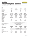
1
American Supercars and Prototypes, LLC
User and
Installation
Manual
Version 1.4
Page ii
User and Installation Manual – ASaP™ MasterShift™ Sequential Shifter
Warranty Information
MasterShift™ Sequential Shifter is for OFF-ROAD use ONLY
Due to the conditions under which MasterShift™ Sequential Shifter operates (Off Road Use Only) all
warranties, express or implied, arising by operation of law or otherwise including, but not limited to, any
warranty for fitness or merchantability for a particular purpose are hereby excluded. Under no
circumstances will American Supercars and Prototypes LLC be liable for consequential, special or
punitive damages arising out of the sale, installation or use of any MasterShift™ product. Any person
selling MasterShift™ products agrees to hold American Supercars and Prototypes LLC harmless from
any and all claims and/or damage awards and further agrees to indemnify American Supercars and
Prototypes LLC for all losses, damages or liability American Supercars and Prototypes LLC may suffer
as a result of such sales.
The remedy set forth herein shall be the exclusive remedy available to any seller, installer or user of
a MasterShift™ product. American Supercars and Prototypes LLC, at its discretion, may repair or
replace any defective MasterShift™ Sequential Shifter unit, within 90 days of purchase. Any and all
costs of removal, installation or re-installation, freight charges and incidental damages or consequential
damages are expressly excluded from this warranty. Normal wear and tear is excluded.
American Supercars and Prototypes' LLC components, including but not limited to MasterShift™
Sequential Shifter units, must be professionally installed as a complete kit as shown in the installation
guide for that particular American Supercars and Prototype LLC product.
American Supercars and Prototypes LLC does not warranty products that are not manufactured by
American Supercars and Prototypes LLC. The Manufacturer of such products must be contacted for
warranty claims. American Supercars and Prototypes LLC shall have no liability for improperly installed
units, units modified from the original specifications by any installer or end user or any American
Supercars and Prototypes LLC product combined with a non-American Supercars and Prototype LLC
product in such a manner as to alter the products original specifications or modify the operation or stated
use of the product in any manner.
Some finish damage may happen to parts as a result of shipping.
Version 1.4
May 10, 2007
ASaP™ MasterShift™ Sequential Shifter – User and Installation Manual
Page iii
Table of Contents
1.
OVERVIEW ................................................................................................................................... 1
1.1
1.2
1.3
1.4
2.
OPERATION.................................................................................................................................. 3
2.1
2.2
2.3
3.
PREPARATION .............................................................................................................................19
SHIFTER CASE ............................................................................................................................20
SHIFT CABLE ..............................................................................................................................20
PADDLE SHIFTER ........................................................................................................................22
WIRING ......................................................................................................................................25
INITIAL CONFIGURATION AND TEST .............................................................................................34
TROUBLESHOOTING ................................................................................................................37
5.1
5.2
6.
INTRODUCTION............................................................................................................................ 7
COMMAND SUMMARY .................................................................................................................. 7
COMMUNICATION TAB ................................................................................................................. 9
CONFIGURATIONS TAB ................................................................................................................11
TRANSMISSION TAB ....................................................................................................................12
SHIFT SETUP TAB .......................................................................................................................13
SHIFT SAFETY TAB .....................................................................................................................15
SPEED SENSOR TAB ....................................................................................................................17
DIAGNOSTICS TAB ......................................................................................................................17
INSTALLATION...........................................................................................................................19
4.1
4.2
4.3
4.4
4.5
4.6
5.
SHIFTING..................................................................................................................................... 3
SAFETY FEATURES ....................................................................................................................... 4
MANUAL BACKUP ........................................................................................................................ 5
MASTERSHIFT™ SEQUENTIAL SHIFTER CONFIGURATION SOFTWARE..................... 7
3.1
3.2
3.3
3.4
3.5
3.6
3.7
3.8
3.9
4.
INTRODUCTION TO THE MASTERSHIFT™ SEQUENTIAL SHIFTER ..................................................... 1
HOW TO READ THIS DOCUMENT ................................................................................................... 1
REQUIREMENTS ........................................................................................................................... 1
PACKAGE CONTENTS ................................................................................................................... 1
DO-IT-YOURSELF CHECKLIST .....................................................................................................37
SUPPORT CONTACT .....................................................................................................................39
APPENDIX ....................................................................................................................................41
6.1
6.2
CONNECTOR PIN-OUTS ...............................................................................................................41
TRANSMISSION SETTINGS ............................................................................................................42
May 10, 2007
Version 1.4
Page iv
User and Installation Manual – ASaP™ MasterShift™ Sequential Shifter
Table of Figures
Figure 1: Communication Tab – Set Up Communications with the Device............................................................ 9
Figure 2: Serial port not connected ..................................................................................................................... 10
Figure 3: Device not found.................................................................................................................................. 10
Figure 4: Configurations Tab – Handling Complete Device Configurations ........................................................ 11
Figure 5: Screenshot of Transmission Tab .......................................................................................................... 12
Figure 6: Shift Setup Tab – Shift Parameters ...................................................................................................... 13
Figure 7: Shift Safety Tab – Shift Safety Features ............................................................................................... 15
Figure 8: Diagnostics Tab – Testing and Troubleshooting................................................................................... 17
Figure 9: Cable with Nut and Washer ................................................................................................................. 21
Figure 10: Cable Mounted in Case ...................................................................................................................... 22
Figure 11: Shifter Case after Mounting Cable ..................................................................................................... 22
Figure 12: Power Wiring .................................................................................................................................... 25
Figure 13: Paddle Wiring.................................................................................................................................... 26
Figure 14: Typical Horn Wiring.......................................................................................................................... 27
Figure 15: Paddle Shifter OneWire Connections ................................................................................................. 28
Figure 16: Gear Sensor Wiring, Remark GearDash (Dash-Mounted) With Remark Sensor ................................. 29
Figure 17: Gear Sensor Wiring, Remark GearDash (Dash-Mounted) With Fortin Sensor.................................... 30
Figure 18: Steering Wheel-Mounted GearDash Wiring, Common Connections................................................... 30
Figure 19: Gear Sensor Wiring, Remark GearDash (Steering Wheel-Mounted) With Remark Sensor ................. 31
Figure 20: Gear Sensor Wiring, Remark GearDash (Steering Wheel-Mounted) With Fortin Sensor .................... 31
Figure 21: Gear Sensor Wiring, Albins Gear Display.......................................................................................... 32
Figure 22: Gear Sensor Wiring, Fortin Gear Display........................................................................................... 32
Figure 23: Clutch Switch Wiring ........................................................................................................................ 33
Figure 24: Optional Switch Inputs and Outputs Wiring....................................................................................... 34
Figure 25: MasterShift Main Connector (J1)....................................................................................................... 41
Figure 26: MasterShift Serial Connector (J2) ...................................................................................................... 41
Figure 27: Paddle Panel Connector (J3) .............................................................................................................. 41
Version 1.4
May 10, 2007
ASaP™ MasterShift™ Sequential Shifter – User and Installation Manual
Page 1
1. Overview
1.1 Introduction to the MasterShift™ Sequential Shifter
The MasterShift™ Sequential Shifter enables you to shift your sequential transmission while leaving your hands
on the steering wheel. It provides a quick and reliable electronically controlled shift. The shifter unit is coupled to
the transmission through a standard shift cable, just like the manual shift lever; this makes installation quick and
easy.
The MasterShift™ Sequential Shifter currently supports Albins, Fortin and Mendeola sequential transmissions.
Other similar transmissions may be supported.
1.2 How to Read This Document
If you have received a vehicle with the MasterShift™ Sequential Shifter pre-installed or if you had it installed by a
qualified installer, the main part of interest for you is section 2 “Operation”. In case you want to learn about
configurable options, check out section 3 “MasterShift™ Sequential Shifter Configuration Software”.
For those who need to install a unit, please read first section 4 “Installation”.
In case you should have trouble with your MasterShift™ Sequential Shifter, please refer to section
5 “Troubleshooting”.
1.3 Requirements
· Vehicle with a supported sequential transmission. Currently supported are:
o Albins AGB-SS5
o Fortin models FRS4, FRS5 and FRS6
o Mendeola models S4, S5, S4D, S5D and HD4
· Remark Industries Fortin or Mendeola Sequential Gear Display (can be ordered together with your
Sequential Shifter) or the factory Albins or Fortin gear indicator.
· Microsoft Windows PC with a standard serial port and with Microsoft .NET installed (for configuration)
1.4 Package Contents
· 1 User manual
· 1 CD-ROM with the MasterShift™ Sequential Shifter configuration software
· 2 Drill templates for mounting the MasterShift™ Sequential Shifter
· 1 MasterShift™ Sequential Shifter
· 4 M6 screws for the case
· 1 Main wiring loom with 23-pin rectangular connector J1 (15 pins populated)
· 1 Steering wheel wiring loom with 8-pin panel-mount round connector J3
· 1 Paddle shifter with coiled cord and connector
· 6 10-32 screws for the paddle shifter
· 1 Serial cable (9-pin D-Sub, female-female)
May 10, 2007
Version 1.4
Page 2
User and Installation Manual – ASaP™ MasterShift™ Sequential Shifter
[This page intentionally left blank.]
Version 1.4
May 10, 2007
ASaP™ MasterShift™ Sequential Shifter – User and Installation Manual
Page 3
2. Operation
This section describes the normal operation of the MasterShift™ Sequential Shifter. It assumes a properly
installed device (see section 4 Installation for installation instructions).
2.1 Shifting
2.1.1 BASIC SHIFTING
Basic shifting is simple: just hit the shift buttons or paddles, and the MasterShift™ Sequential Shifter will push or
pull the shift cable, as you would have done manually before you had it. It is also possible to “stack” multiple
shifts by pressing the paddle or button several times. The Sequential Shifter will then execute just as many shifts
in a row.
It won’t allow you to shift down past neutral or reverse (depending on your transmission), and it won’t allow you
to shift up past the highest gear of the transmission. Other than that, you are free to shift as you did before: shift
with or without clutch (see section 2.1.3 Clutchless Shifting for requirements); shift multiple times during one
press of the clutch pedal; … the Sequential Shifter follows you and your driving style.
Just as with manual shifting, sometimes the dog ears may not line up properly and a shift may not complete. In the
same way as with manual shifting — when you press the shift lever a second time —, hit the button or paddle
again. This is normal in certain circumstances and does not indicate a malfunction of the unit.
2.1.2 SPECIAL SHORT SHIFT TO NEUTRAL
Some transmissions have their neutral gear between the first and second gears; it can be reached with a shorter
shift than normally. The Sequential Shifter supports such transmissions (see also section 3.5 Transmission Tab).
However, when shifting up from first gear or down from second gear, it needs to know whether the driver wants to
shift into the next “normal” gear or into neutral.
It uses the same mechanism that with other transmissions is used for the neutral safety feature (see section
2.2.1 Neutral Safety). When the shift safety button is enabled, pressing it together with the shift up or down button
will cause a shift to neutral. Alternatively, the neutral delay can be set to a time up to 5 seconds, and when the
shift button is pressed for at least the configured time before it is released, the Sequential Shifter will shift into
neutral – otherwise, it will shift into the “normal” target gear (first or second gear). If both are enabled, pressing
the safety button causes a shift to neutral without requiring the configured delay.
Required for the special neutral switch feature is an additional shift safety push-button. (See also section 3.7 Shift
Safety Tab for the configuration options and section 4.5.5 Optional Switch Inputs and Outputs for the switch
wiring.)
2.1.3 CLUTCHLESS SHIFTING
Caution: Shifting without clutch is an advanced technique that may cause severe damage to a transmission
if performed improperly. It should be performed with extreme care and full awareness of the consequences.
Shifting without clutch with the Sequential Shifter is not less dangerous than shifting manually without
clutch. American Supercars and Prototypes, LLC can not be held responsible for transmission damage due
to shifting without clutch.
Note: Before enabling and using the clutchless shifting, please check with your transmission manufacturer
to insure that they recommend and support full throttle shifting (clutchless shifting).
Some advanced drivers prefer to execute upshifts without pressing the clutch pedal (downshifts should always be
completed using the clutch). Generally this is done by “blipping” the throttle: just before (and during) the shift, the
May 10, 2007
Version 1.4
Page 4
User and Installation Manual – ASaP™ MasterShift™ Sequential Shifter
driver releases the throttle. This causes the engine to reduce the torque, which allows the dog ears of the
transmission to relax so that they can be shifted into another gear.
The same technique can be used with the Sequential Shifter in its default configuration. It may require some
adjustment for the driver to the new and different shift controls, but after some time it will work just like before
when shifting manually.
But the MasterShift™ Sequential Shifter also provides an optional feature to make this still more convenient. The
EMS Control output can be connected to an engine management system (EMS), to request a torque reduction
before and during the shift movement. Torque reduction can be achieved for example by limiting the fuel supply,
changing the ignition timing, or limiting the engine rotation. The Sequential Shifter activates the output a short
time before the shift movement, giving the engine time to actually reduce the torque on the transmission, and
deactivates it immediately after the shift, so that the engine again supplies full torque.
Note: Support with all engine management systems cannot be guaranteed. Most often the engine
management system will need to be specially setup to work with the MasterShift. Certain Delphi engine
management systems even require an auxiliary pin to be wired to the outside plug.
Caution: You will need to setup the pre-shift delay time if you are to use the MasterShift to do clutchless
upshifts. Due to variances in motors, transmissions, and driving styles, you may need to spend some time
configuring this value to an optimal level. A wrong value can lead to transmission damage.
In case the driver wants to disable this feature (and with that “bypass” the short time the Sequential Shifter waits
prior to the actual shift movement), an optional switch input is provided for an EMS Control Switch. When this
input is switched to ground, the feature is disabled and the shifter shifts normally, without waiting for the engine
to reduce torque.
If you have a clutch switch installed (see 2.2.2 Clutch Safety), the EMS Control output is deactivated for any shift
with the clutch pedal depressed. This prevents unnecessary engine rpm drops when shifting with clutch.
It is recommended that you always use the clutch for downshifts.
(See also section 3.6 Shift Setup Tab for the configuration option and section 4.5.5 Optional Switch Inputs and
Outputs for the required wiring of the EMS control input and output.)
2.2 Safety Features
While the basic functionality is enough for many purposes, there are situations where undesirable shifts or shift
attempts may happen. These can be prevented by the following shift safety features. All these can be individually
enabled and disabled to suit your style.
2.2.1 NEUTRAL SAFETY
When the neutral safety switch is enabled, a shift safety push-button must be pressed when the driver wants to
shift from first gear to neutral. When the neutral safety delay is enabled, the driver must hold the shift button for a
time longer than the configured neutral safety delay time for a shift from first gear into neutral. If both the switch
and the delay are enabled, pressing the switch will allow a shift into neutral, bypassing the otherwise required
delay.
The purpose of this feature is to prevent accidental shifts into neutral gear during normal driving. Multiple presses
of the downshift button or paddle (without pressing the shift safety button) are now safeguarded from shifting into
neutral. (This works a bit differently with transmissions that have their neutral gear between the first and second
gear and require a special short shift for a shift into neutral. See section 2.1.2 Special Short Shift to Neutral for
details.)
Required for the neutral safety switch feature is an additional shift safety push-button. (See also section 3.7 Shift
Safety Tab for the configuration options and section 4.5.5 Optional Switch Inputs and Outputs for the switch
wiring.)
Version 1.4
May 10, 2007
ASaP™ MasterShift™ Sequential Shifter – User and Installation Manual
Page 5
2.2.2 CLUTCH SAFETY
When the clutch safety feature is enabled, the driver is not allowed to shift from neutral into first gear without
pressing the clutch, and the clutch is also required for all downshifts. The purpose of this feature is to prevent shift
attempts in situations when normally the clutch pedal should be pressed.
Note: Clutchless upshifts are still allowed, so be cautious to not upshift without the clutch being depressed,
“blipping” the throttle, or having the EMS control output properly installed and setup.
Required for this feature is a switch that gets activated (closed or opened) when the clutch pedal is pressed and the
clutch is disengaged. (See also section 3.7 Shift Safety Tab for the configuration options and section 4.5.4 Clutch
Switch for the switch wiring.)
Note: The use of this feature is highly encouraged. Shifting without using the clutch may cause damage to
the transmission. This feature also keeps the vehicle from accidentally being shifted into a forward gear
while idling in neutral.
Often the clutch safety switch can be a hydraulic pressure switch (similar to a hydraulic brake switch). Please be
aware that if you are using a hydraulic pressure switch, it may allow a shift to occur when the clutch is not fully
disengaged from the transmission. Therefore you should disengage the clutch prior to pressing the
upshift/downshift paddle/button. If you are using a normal lever switch/push button switch, make sure you place
the switch at a location where the switch is depressed when the clutch is fully disengaging the motor from the
transmission.
2.2.3 REVERSE SAFETY
Reverse safety has two different modes of operation, depending on your transmission:
· Transmissions without a reverse gear in the normal shift lever shift sequence (Mendeola)
The reverse safety switch is always enabled, but still must be wired to a switch to be functional. The
Sequential Shifter will not attempt any shift movements while the transmission is in reverse gear, as
indicated by a closed reverse gear switch. The transmission itself will not allow the forward lever to be
moved out of neutral position while in reverse; so this is just an additional safeguard to prevent unnecessary
stress on the shift components. (There is no reverse safety delay for these transmissions.)
Required for this feature is a switch that gets closed when the transmission is in reverse gear. (See also
section 3.7 Shift Safety Tab for the configuration option and section 4.5.5 Optional Switch Inputs and
Outputs for the required wiring.)
· Transmissions with a reverse gear in the normal shift lever shift sequence (Albins, Fortin)
When the reverse safety switch is enabled, the Sequential Shifter requires that the shift safety push-button
is pressed when shifting into reverse gear. This is the same button as used for the neutral safety feature (see
section 2.2.1 above). When the reverse safety delay is enabled, the driver must hold the shift button for a
time longer than the configured time for a shift into reverse. If both the switch and the delay are enabled,
pressing the switch will allow a shift into reverse, bypassing the otherwise required delay.
Required for the reverse safety switch feature is an additional shift safety push-button. (See also section
3.7 Shift Safety Tab for the configuration option and section 4.5.5 Optional Switch Inputs and Outputs for
the switch wiring.)
2.3 Manual Backup
As with every device, the shifter unit may fail. However, due to the unobtrusive installation process, a manual
backup function is easy to accomplish with a minimal number of tools and a little pre-planning.
In the unlikely failure of the device, there are two options depending on the installation. Your first option is to
disconnect the shift cable from the shift lever under the cover, remove the shift cable from the case, and connect it
May 10, 2007
Version 1.4
Page 6
User and Installation Manual – ASaP™ MasterShift™ Sequential Shifter
to a normal manual shift lever. Since nothing has changed from the shift cable towards the transmission, this
setup works for manual shifting just like before the installation of the shifter.
If the shift cable to the MasterShift™ Sequential Shifter is too short to reach your manual shift lever, or if it is
difficult to get to the manual shift lever, then a second option is to leave a cable hooked to the manual shift lever.
Run the cable from the manual shift lever to the back near the transmission. Secure the cable out of the way of any
moving parts. Now if you have a failure, all you must do is disconnect the cable that goes from the transmission
shift lever to the Sequential Shifter, then install the manual shift cable back onto the transmission shift lever, and
then secure the cable that goes to the Sequential Shifter up and out of the way.
Version 1.4
May 10, 2007
ASaP™ MasterShift™ Sequential Shifter – User and Installation Manual
Page 7
3. MasterShift™ Sequential Shifter Configuration Software
3.1 Introduction
After the MasterShift™ Sequential Shifter has been properly installed in the vehicle (see section 4 Installation), it
can be configured through its serial port. The following is required for being able to configure it:
· A Microsoft Windows PC with the Microsoft .NET framework version 1.1 installed. If you haven’t yet,
please use the Windows Update feature to install it. (It will be installed from the CD during installation if it
isn’t already installed on your computer. But it is recommended to check the Windows Update anyway, to
get recommended updates for your system.)
· A standard serial port. If your computer doesn’t have a serial port, you may be able to use a USB-to-Serial
converter. Compatibility with all USB-to-Serial converters can not be guaranteed.
· The ASaP™ MasterShift™ Sequential Shifter Configuration software. It came with your MasterShift™
Sequential Shifter unit on the CD-ROM. Install the software on your PC by running the installer file
setup.exe.
· The 9-pin D-Sub, female-female serial cable that came with your MasterShift™ Sequential Shifter unit.
(This is not a standard serial cable. Please do not try to use a standard serial cable – it will not work! It
is possible, however, to extend the provided cable with a standard 9-pin male-female straight wired serial
cable.)
Connect the serial port (the 9-pin male D-Sub connector) of the MasterShift™ Sequential Shifter to the PC’s
serial port with the serial cable you received with your Sequential Shifter. You may need to remove the small
plastic cover over the serial port on the Sequential Shifter. To do this remove the two small screws on either side
of the plastic cover and then slide the cover off, exposing the serial port pins. Once the serial cable is hooked up,
switch on the (ignition) power to the Sequential Shifter. Run the MasterShift™ Sequential Shifter Configuration
software and select the COM port – and you are ready to go.
This description is for the version 1.2.2 of the MasterShift™ Sequential Shifter configuration software (see section
3.3 Communication Tab).
3.2 Command Summary
Below you find a table summarizing all configuration items. The required settings for the supported transmission
models are listed in appendix 6.2 Transmission Settings.
Tab Page
Configuration Item
Unit
Range
Required
Transmission
Number of gears
(none)
4…6
Yes
Reverse gear in sequence
(none)
On, Off
Yes
Special neutral sequence
(none)
On, Off
Yes
Gear positions RN123456
Gear Sensor
0…1023
Yes
Gear ratios 123456
-
-
(Future enhancement)
Shift direction
(none)
Pull=Upshift,
Pull=Downshift
Yes
EMS Pre-shift delay
Milliseconds (ms)
0…2000
No (0 disables)
Stall timeout
Milliseconds (ms)
50…2000
Yes
Shift Setup
May 10, 2007
Version 1.4
Page 8
Tab Page
Shift Safety
Speed Sensor
User and Installation Manual – ASaP™ MasterShift™ Sequential Shifter
Configuration Item
Unit
Range
Required
OneWire paddles
(none)
Paddles=Upshift,
Paddles=Downshift
No (Yes if OneWire
board installed)
Full shift lever target
Δpos (0.4%)
30…125
Yes
Full shift lever end pos.
Δpos (0.4%)
30…125
Yes
Full shift overshoot
Δpos (0.4%)
0…40
Yes
Half shift lever target
Δpos (0.4%)
30…125
No (Yes if special
neutral seq.)
Half shift lever end pos.
Δpos (0.4%)
30…125
No (Yes if special
neutral seq.)
Half shift overshoot
Δpos (0.4%)
0…40
No (Yes if special
neutral seq.)
Shift offset – push
Δpos (0.4%)
0…25
No
Shift offset – pull
Δpos (0.4%)
0…25
No
Neutral safety/shift switch
(none)
On, Off
No (Off disables)
Neutral safety/shift
timeout
Milliseconds (ms)
0…5000
No (0 disables)
Reverse safety switch
(none)
On, Off
No (Off disables)
Reverse safety timeout
Milliseconds (ms)
0…5000
No (0 disables)
Clutch safety switch
enable
(none)
On, Off
No (Off disables)
Clutch switch power
(none)
Sw to Gnd-Ext. PU,
Sw to Gnd-Int. PU,
Sw to Pos-Ext. PD,
Sw to Pos-Int. PD
No (Yes if clutch
safety is enabled)
Clutch switch polarity
(none)
Normally Open,
Normally Closed
No (Yes if clutch
safety is enabled)
Engine max. rpm
-
-
(Future enhancement)
Pulses per revolution
-
-
(Future enhancement)
Speed sensor location
-
-
(Future enhancement)
Front tire circumference
-
-
(Future enhancement)
Rear tire circumference
-
-
(Future enhancement)
· Position units: Position values are given in a percentage of the maximum movement. The outer limit
position close to the downshift position has the value 0; the outer limit position close to the upshift position
has the value 250. (The position unit is [0.4%].) Example values are:
25 [0.4%]
=
10%
100 [0.4%] =
40%
125 [0.4%] =
50% (center)
200 [0.4%] =
80%
250 [0.4%] =
100% (typical upshift)
Version 1.4
May 10, 2007
ASaP™ MasterShift™ Sequential Shifter – User and Installation Manual
Page 9
· Milliseconds: Times are set in milliseconds (short “ms”). Thousand milliseconds are equal to one second
(short “s”). Example values are:
500 [ms]
=
0.5 s
800 [ms]
=
0.8 s
1000 [ms]
=
1.0 s
2000 [ms]
=
2.0 s
3.3 Communication Tab
The Communication tab is the first tab that is visible, and as long as no connection to a Sequential Shifter device
has been established, it is the only tab that is accessible. Before being able to use the program, the correct serial
port must have been selected and a powered device must be connected to the serial port (see below).
Figure 1: Communication Tab – Set Up Communications with the Device
· Serial Port Configuration: The MasterShift™ Sequential Shifter Configuration software needs to know on
which serial port you have the Sequential Shifter connected.
Select the serial port where you have the MasterShift™ Sequential Shifter connected and make sure that no
other application (like a terminal, modem or fax software) is using it. If you do not know which serial port
the MasterShift™ Sequential Shifter is connected to, you can go through the list of available serial ports
starting at COM 1, until one of the COM ports connects and recognizes the MasterShift™ unit.
The MasterShift™ Sequential Shifter software opens at the Communication tab, where it initially shows
that neither the serial port is connected (“Serial port not connected”) nor has a Sequential Shifter been
found (“MasterShift not found”); see Figure 2. After selecting an available serial port in the drop-down
list, the software indicates that it could connect to the serial port (“Serial port connected”); see Figure 3.
If you don’t see this message, please make sure that you have selected the correct serial port and that it is
available (that is, that no other program is using it).
At this point, the configuration software tries to communicate with the Sequential Shifter. Once it finds the
device, it queries it for serial number and version information and then considers itself properly connected
May 10, 2007
Version 1.4
Page 10
User and Installation Manual – ASaP™ MasterShift™ Sequential Shifter
(“MasterShift found”); see Figure 1. If the software can’t find your Sequential Shifter (see Figure 3),
please make sure it is connected to the correct serial port and that it is powered.
If you are unable to get any of the COM ports to connect to the Sequential Shifter please refer to the
Troubleshooting guide (section 5 Troubleshooting).
Figure 2: Serial port not connected
Figure 3: Device not found
· Serial Number: This is the unit’s serial number. Please always have the serial number handy when talking
to ASaP support.
· Firmware Version: This number is the version of the firmware of the controller board inside the
MasterShift™ Sequential Shifter.
· Hardware Version: This number is the version of the electronic hardware of the controller board inside
the MasterShift™ Sequential Shifter.
· Software version: This is the version of the ASaP™ MasterShift™ Sequential Shifter Configuration
software.
Version 1.4
May 10, 2007
ASaP™ MasterShift™ Sequential Shifter – User and Installation Manual
Page 11
3.4 Configurations Tab
The Configurations tab provides access to complete device configurations. At the moment, the only function
available is to reset the device to its factory default configuration.
Figure 4: Configurations Tab – Handling Complete Device Configurations
· Load Default Configuration: Clicking this button will reset your MasterShift™ Sequential Shifter to the
default configuration. All your previous settings will be lost.
May 10, 2007
Version 1.4
Page 12
User and Installation Manual – ASaP™ MasterShift™ Sequential Shifter
3.5 Transmission Tab
The Transmission tab contains settings for the characteristics of your particular transmission. All active settings
on this tab are required. See also appendix 6.2 Transmission Settings for the required settings for the supported
transmission models.
Figure 5: Screenshot of Transmission Tab
· Number of forward gears: It is the number of forward gears in your transmission. Default is 4; set it to 5
or 6 if you have a five-speed or six-speed transmission.
The gear position settings for fifth and sixth gear are only enabled when the appropriate number of forward
gears is selected.
· Reverse gear in sequence: This setting determines whether there is a reverse gear as part of the shift
sequence, past (shifting downwards from) the neutral or first gear. (Enable this feature only for
transmissions that have a reverse gear that is part of the normal up/down shift sequence, like the Albins
and Fortin transmissions.)
This configuration also enables the Reverse gear position setting and the reverse safety configurations (see
section 3.7 Shift Safety Tab).
· Special neutral sequence: Normally, the neutral gear is a downshift from first gear (and an upshift from
reverse gear, if there is a reverse gear in the shift sequence). Some transmissions have a motorcycle-style
neutral gear that is a half shift above first and a half shift below second gear. Enable this special neutral
sequence by setting this item to “On”.
When this configuration item is set to “On”, the Neutral and Gear 1 gear position settings change place and
the neutral safety settings become neutral shift settings (see section 3.7 Shift Safety Tab).
· Gear positions: This section allows the calibration of gear positions. To calibrate the positions, disconnect
the shift cable from the transmission shift lever. Place the transmission first in neutral (if it isn’t already) as
shown on the gear indicator (with vehicle ignition on, motor off). Use a suitable tool or simply move the
transmission shift lever with your hand if you need to place it into neutral. Once in neutral, click the
“Reload” button in the Gear Positions box. Replace the value in the white “Neutral” box with the value you
Version 1.4
May 10, 2007
ASaP™ MasterShift™ Sequential Shifter – User and Installation Manual
Page 13
see in the “Current” box. Using your hands or a tool, place the transmission into another gear (most likely
first gear) and then click the “Reload” button again (you can always use the gear indicator to verify the gear
you are currently in and calibrating). Replace the value in the white box appropriate for that gear with the
value you see in the “Current” box. Repeat these steps for all other gears of the transmission. If you have a
Fortin or Albins transmission, don’t forget to calibrate the reverse gear. You may need to rock the vehicle
to line up the dog rings to get the transmission to shift. Once you are finished, place the transmission back
into neutral and hook up the shift cable.
· Gear ratios: (Future enhancement.)
3.6 Shift Setup Tab
The Shift Setup tab provides configurations related to the specific vehicle’s shift cable installation and the shift
behavior. See also appendix 6.2 Transmission Settings for the required settings for the supported transmission
models.
Figure 6: Shift Setup Tab – Shift Parameters
· Shift Direction: This configuration is required. Default is that a pull on the MasterShift end of the cable
causes an upshift. If a pull causes a downshift, set this item accordingly. Usually this setting needs to be
changed depending on if you have a mid-engine or rear engine vehicle. Prior to attempting to shift with the
MasterShift unit, be sure this setting is set correctly.
· EMS pre-shift delay: The Sequential Shifter can control an engine management system (EMS) to
momentarily reduce the engine torque during an upshift, thus allowing an upshift without having to press
the clutch. (Downshifts still require the use of the clutch.) This works much in the same way as when the
driver manually “blips” the throttle to be able to upshift without the use of the clutch. (See also section
2.1.3 Clutchless Shifting.)
The Sequential Shifter activates the EMS Control output for a short, programmable time before starting the
shift movement, to allow the engine to reduce torque before trying to disengage the dog ears. This time
(measured in milliseconds) can be configured here. The required value depends on the engine, the EMS,
May 10, 2007
Version 1.4
Page 14
User and Installation Manual – ASaP™ MasterShift™ Sequential Shifter
the driving style and other factors and needs to be decided experimentally. 200 ms may be a good value to
start with.
The pre-shift delay and the EMS Control output are only active for upshifts from a forward gear, when the
clutch is not pressed and the optional EMS Control switch is not activated.
Caution: Shifting without the clutch can severely damage your transmission if done improperly.
American Supercars and Prototypes, LLC accepts no responsibility for transmission damage due to
shifting without the clutch.
Proper configuration of this feature is essential. American Supercars and Prototypes, LLC does not
recommend setting the EMS Control output for any shorter than 110ms. A value lower then 110ms
can cause an adverse pull on the shift cable when the dog ears are pulled together under load.
Note: Before enabling and using the clutchless shifting, please check with your transmission
manufacturer to insure that they recommend and support full throttle shifting (clutchless shifting).
Due to variances in motors, transmissions and driving styles, you may need to spend some time
configuring this value to an optimal level.
If you don’t use this feature, leave the value at its default of 0. This prevents any unnecessary delay
in shifting.
· Stall timeout: In some situations, the dog ears may not be able to engage and the shift movement may stall.
The time the Sequential Shifter waits (and keeps trying) until it decides that the shift is stalled is set here
(in milliseconds). The default is 800 ms (or 0.8 s).
A longer timeout has the effect of fewer unsuccessful shifts, at the expense of a longer delay in the case of a
shift where the dog ears really can not engage. A shorter timeout has the effect of a shorter delay in the case
of unsuccessful shifts, at the expense of a slightly higher number of such shifts (the ones that would have
succeeded with a longer time to try).
· One-wire paddles: Most sequential transmissions are installed in off-road vehicles without a horn wire in
the steering column. Those however that do have such a horn wire, may opt for the ASaP OneWire paddle
shifter instead of the normal paddle assembly. Its advantage is that no umbilical cord is required; all
information and power is sent over the single horn wire. This configuration item determines whether the
paddles trigger an upshift or a downshift. (The buttons trigger the respective other command.)
· Full shift lever positions: These values should be set according to the table for your transmission model in
section 6.2 Transmission Settings. The values determine the extent of the lever’s shift movement. In some
cases, individual customization may be required.
· Half shift lever positions: These values are only available when the special neutral sequence (see section
3.5 Transmission Tab) is enabled. They should be set according to the table for your transmission model in
section 6.2 Transmission Settings. The values determine the extent of the lever’s shift movement. In some
cases, individual customization may be required.
· Shift offsets: In some cases, excessive cable slack may cause shifts to fail. These shift offset settings help
working around the cable slack problems. Please contact ASaP support if you should have high numbers of
failed shifts.
Version 1.4
May 10, 2007
ASaP™ MasterShift™ Sequential Shifter – User and Installation Manual
Page 15
3.7 Shift Safety Tab
The Shift Safety tab allows you to set up features that help prevent accidental or harmful shift commands from
being executed. Even though these features are optional, they are still highly recommended. See also appendix
6.2 Transmission Settings for the required settings for the supported transmission models.
Figure 7: Shift Safety Tab – Shift Safety Features
· Neutral safety: Depending on whether the special neutral sequence is enabled or not (see section
3.5 Transmission Tab), this feature has two modes:
o Special Neutral Sequence not Enabled – Neutral Safety
The MasterShift™ Sequential Shifter allows pressing the shift button repeatedly, causing a number
of repeated shifts. This can be useful in a situation where the driver wants to get down a few gears as
quickly as possible. In the heat of the moment, it is possible to hit the downshift button or paddle
once to often and end up in neutral. This can be avoided by enabling one or both of the neutral safety
options.
When the neutral safety switch is enabled, shifts from forward gears into neutral are only allowed if
the shift safety button is pressed, in addition to the downshift button or paddle. When the neutral
safety timeout is set, the downshift button or paddle must be pressed for the set time for a shift into
neutral to occur. When both are enabled and the shift safety switch is activated, it is not necessary to
wait for the set timeout; a shift to neutral is immediately possible. (See also section 2.2.1 Neutral
Safety.)
Note: If you are using the neutral safety timeout, it is recommended that you set it above 500 ms
(0.5 s), otherwise it may be possible to inadvertently shift into reverse gear due to the short timeout.
o Special Neutral Sequence Enabled – Neutral Shift
When the special neutral sequence is enabled, the driver needs a way to tell the Sequential Shifter
whether an upshift from first gear or a downshift from second gear should be a normal shift into
May 10, 2007
Version 1.4
Page 16
User and Installation Manual – ASaP™ MasterShift™ Sequential Shifter
second or first gear respectively or whether it should be a half-sized shift into neutral. These two
options that in other transmissions provide the neutral safety feature help here with this.
When the neutral shift switch is enabled, pressing the shift safety switch together with an upshift or
downshift button or paddle indicates that the shift should be a shift to neutral. When the neutral shift
timeout is set, a shift to neutral occurs when the appropriate shift command (upshift in first gear,
downshift in second gear) is given by pressing the shift button or paddle for the configured time.
Shorter presses result in a normal upshift or downshift. When both options are enabled, pressing the
shift safety button allows a shift to neutral without pressing the shift button or paddle for the
configured time. (See also section 2.1.2 Special Short Shift to Neutral.)
Note: One of these two options has to be enabled. If not, the Sequential Shifter has no way to tell
whether an upshift from first or a downshift from second should be a shift to neutral or a normal
shift.
Note: If you are using the neutral safety timeout, it is recommended that you set it above 500 ms
(0.5 s), otherwise it may be possible to inadvertently shift into reverse gear due to the short timeout.
In both cases, see also the shift safety switch wiring in section 4.5.5 Optional Switch Inputs and Outputs.
· Reverse safety: Depending on whether reverse gear is enabled or not (see section 3.5 Transmission Tab),
this feature has two modes:
o Reverse Gear not Enabled – Reverse Switch Shift Lock
The Mendeola transaxles (no reverse gear in the shift sequence) block the forward shift lever while
the transmission is in reverse gear. However, with a reverse switch connected to the Sequential
Shifter (see also the reverse switch wiring in section 4.5.5 Optional Switch Inputs and Outputs), the
Sequential Shifter can prevent even shift attempts while the transmission is in reverse gear.
This safety feature prevents any shift attempts while the reverse gear switch is closed. Only a
properly installed, functioning switch on the reverse lever will prevent forward shifts from occurring
when the manual shift lever is in reverse position.
o Reverse Gear Enabled – Reverse Safety
Albins and Fortin transmissions have a reverse gear as part of the normal shift sequence. Enabling
this feature helps prevent accidental shifts into reverse.
When the reverse safety switch is enabled, shifts into reverse are only allowed if the shift safety
button is pressed, in addition to the downshift button or paddle. When the reverse safety timeout is
set, the downshift button or paddle must be pressed for the set time for a shift into reverse to occur.
When both are enabled and the shift safety switch is activated, it is not necessary to wait for the set
timeout; a shift to reverse is immediately possible. (This works similarly to the neutral safety feature
described earlier.)
Note: If you are using the reverse safety timeout, it is recommended that you set it above 500 ms
(0.5 s), otherwise it may be possible to inadvertently shift into reverse gear due to the short timeout.
· Clutch safety: When a clutch switch is installed in the vehicle, it can be used to provide additional shift
safety by preventing shifts that normally require the clutch to be engaged.
When this feature is enabled, shifts out of neutral into reverse or first gear, shifts from reverse into first
gear (for transmissions with the special neutral sequence) and all downshifts will only be executed if the
clutch has been disengaged (determined by an activated clutch switch).
The clutch switch may be connected in a number of ways. The following two configuration items provide
the necessary options:
o Clutch input power: The clutch input may be connected to a switch to ground or a switch to
positive (12 V battery), and that switch may have an external pull-up or pull-down or it may need a
Version 1.4
May 10, 2007
ASaP™ MasterShift™ Sequential Shifter – User and Installation Manual
Page 17
supply from the Sequential Shifter. This drop-down list provides options for all four possible switch
combinations. See also 4.5.4 Clutch Switch for a detailed description of the wiring options.
o Clutch input polarity: The clutch input may be normally open (closed when the clutch pedal is
pressed) or normally closed (open when the clutch pedal is pressed). Set this value accordingly.
· Engine max rpm: (Future enhancement.)
(See also the description of the safety features in section 2.2 Safety Features.)
3.8 Speed Sensor Tab
(Future enhancement.)
3.9 Diagnostics Tab
Figure 8: Diagnostics Tab – Testing and Troubleshooting
· Board Temperature: The Sequential Shifter reads the temperature inside the case. It is displayed here in
°C.
· Upshift Count: The Sequential Shifter keeps track of the number of shifts. This is the number of upshifts.
· Downshift Count: The Sequential Shifter keeps track of the number of shifts. This is the number of
downshifts.
· Shift Commands: It is possible to cause shift movements without using the shift paddles or steering wheel
buttons, by using these software buttons. (The Shift to Neutral button only has an effect if the transmission
can be shifted into neutral gear with one shift. On transmissions with the special neutral sequence it will
trigger the required half shift movement.) Note that without a gear sensor connected, the controller sees the
transmission as being in neutral or reverse and therefore won’t allow a downshift.
May 10, 2007
Version 1.4
Page 18
User and Installation Manual – ASaP™ MasterShift™ Sequential Shifter
Caution: Using the shift commands will put your transmission into various gears which could cause
the vehicle to start moving. Make sure your vehicle is properly secured or on jack stands before
using the shift commands.
Version 1.4
May 10, 2007
ASaP™ MasterShift™ Sequential Shifter – User and Installation Manual
Page 19
4. Installation
4.1 PREPARATION .............................................................................................................................19
4.2 SHIFTER CASE ............................................................................................................................20
4.3 SHIFT CABLE ..............................................................................................................................20
4.3.1 Cable Layout ........................................................................................................................20
4.3.1.1
4.3.1.2
4.3.1.3
4.3.1.4
Use Original Cable (with Backup) ................................................................................................20
Use New Cable (with Backup)......................................................................................................21
Use Two Cables with Two Mounts (with Backup) ........................................................................21
Use New Cable (no Backup) .........................................................................................................21
4.3.2 Hook Up End Points.............................................................................................................21
4.4 PADDLE SHIFTER ........................................................................................................................22
4.4.1 Preparations .........................................................................................................................23
4.4.1.1 Blank Steering Wheels .................................................................................................................23
4.4.1.2 3-Bolt Hubs ..................................................................................................................................23
4.4.2 Paddle Shifter with Umbilical Cord......................................................................................23
4.4.2.1 Dash-Mounted GearDash..............................................................................................................23
4.4.2.2 Steering Wheel-Mounted GearDash ..............................................................................................23
4.4.2.3 Quick Disconnect Panel Mount Connector ....................................................................................24
4.4.3 Paddle Shifter with OneWire Board .....................................................................................24
4.5 WIRING ......................................................................................................................................25
4.5.1 Power Wiring.......................................................................................................................25
4.5.2 Paddle Wiring......................................................................................................................26
4.5.2.1 Paddle with Umbilical Cord..........................................................................................................26
4.5.2.2 Paddle Shifter with OneWire Board ..............................................................................................27
4.5.2.2.1 Connect OneWire Circuit........................................................................................................28
4.5.2.2.2 Connect Horn Relay................................................................................................................29
4.5.3 Gear Sensor Wiring .............................................................................................................29
4.5.3.1
4.5.3.2
4.5.3.3
4.5.3.4
Dash-Mounted Remark GearDash.................................................................................................29
Steering Wheel-Mounted Remark GearDash .................................................................................30
Albins Gear Display .....................................................................................................................31
Fortin Gear Display ......................................................................................................................32
4.5.4 Clutch Switch ......................................................................................................................33
4.5.5 Optional Switch Inputs and Outputs.....................................................................................34
4.6 INITIAL CONFIGURATION AND TEST .............................................................................................34
4.1 Preparation
Please read all relevant parts of this entire section before installing anything. Some parts depend on others, and
often knowledge of other parts is required to fully understand all consequences of decisions made during
installation.
Caution: Please be aware that installing the MasterShift™ Sequential Shifter requires a qualified person
familiar with maintaining and installing vehicle mechanics and wiring and qualified to execute the
required installations. American Supercars and Prototypes, LLC accepts no responsibility for defects or
damages that arise from incorrect installations. It is to be fully understood that you are accepting all risks
involved with the installation of the MasterShift™ Sequential Shifter and the associated devices. If you are
unable to locate a qualified person, please contact American Supercars and Prototypes, LLC and we will be
happy to help you locate an installer in your area.
The Remark GearDash or a factory-supplied display is required for the ASaP™ MasterShift™ Sequential Shifter
to work properly. The Remark GearDash comes in two versions: dash-mounted and steering wheel-mounted. If
you ordered a dash-mounted GearDash display, please install it now following the installation instructions that
May 10, 2007
Version 1.4
Page 20
User and Installation Manual – ASaP™ MasterShift™ Sequential Shifter
came with it. If you ordered a steering wheel-mounted display, the installation is explained below in section 4.4
Paddle Shifter.
In any case, before completing the wiring, please read section 4.5 Wiring; this section explains how to integrate
the Sequential Shifter wiring with the GearDash and factory transmission wiring.
4.2 Shifter Case
Find a suitable location for the shifter case. It should have a flat mounting surface and be reasonably protected
from water and dirt and it needs enough space on the side to plug in and out the connectors and mount the shift
cable once the case is secured.
If you feel the shifter is in a location that may get submerged, it is highly recommended that you mount the shifter
case upside down. This will create a pocket of air inside the shifter case if you were to submerge the vehicle for a
very short time.
Mount the shifter case firmly to the surface. It has four M6 threaded holes on each of two sides that allow the case
to be fixed with the four provided (or other, suitable) M6 screws. Use one of the drill templates for your
convenience. It is recommended that you use lock washers or Loctite on the M6 screws that hold the case down.
Caution: The M6 threaded holes are capped and therefore you cannot use screws that thread into the case
more than 10 mm (3/8” or 0.4”)
If it is impossible to get behind the surface to fasten the screws, a mounting plate can be used that allows
mounting without having to go behind the surface.
4.3 Shift Cable
Caution: Do not use a hard linkage (a shift rod) between the transmission shift lever and the MasterShift
shift lever. The MasterShift unit was designed to work with shift cables and American Supercars and
Prototypes, Inc. does not support installations with a hard linkage.
The MasterShift™ Sequential Shifter comes with a ¼” ball joint quick disconnect fitting, which can be replaced to
suit your shift cable needs. Just make sure that the stud you use has a ¼-28 thread and that the thread length is no
more than ¼” or the threads will bottom out onto the base plate, which will cause the shifter lever to be unable to
move. If you need to purchase a new shift cable, get a good quality cable with 2 inches (5 cm) of throw.
Note: Control Cables Inc (at http://www.controlcables.com) sells suitable shift cables. Use the part number
173LTT-2-XX when ordering and replace the XX with the length of cable that you need in inches.
Example: 173LTT-2-48 is a 48” (4’) shift cable. When measuring for your cable length use end to end
measurements, i.e. from the cable mounting hole on the transmission shift lever, to the ball joint quick
disconnect stud on the MasterShift.
4.3.1 CABLE LAYOUT
You are now ready to hook a shift cable up to the Sequential Shifter unit, and there are four ways that you can do
it. The first three options allow you to leave the manual forward shift lever in the vehicle as a backup, and the
fourth option is without backup.
4.3.1.1 Use Original Cable (with Backup)
Depending on the placement of the Sequential Shifter, you may be able to just disconnect the end of the cable that
goes from the manual forward shift lever and use that to hook your Sequential Shifter up to your transmission.
Then if for some reason there is a failure, you can simply disconnect the cable end that is in the Sequential Shifter
and connect it back up to the manual shift lever in your center console. This requires that you have easy access to
the manual forward shift lever once the vehicle is fully built, and that the cable has enough length in it to go
between the two devices.
Version 1.4
May 10, 2007
ASaP™ MasterShift™ Sequential Shifter – User and Installation Manual
Page 21
4.3.1.2 Use New Cable (with Backup)
A second way that still allows you to have a manual shift lever as a backup is to disconnect the shift cable from the
transmission that runs up to the manual forward shift lever. Zip tie, or otherwise secure the cable that runs up to
the manual forward shift lever somewhere in proximity to the shift lever that is on the transmission, but out of the
way of moving parts. You will then need to purchase a second shift cable that you will install from the Sequential
Shifter to your transmission shift lever. In this instance, if you must hook back up to your manual shift lever, then
all you must do is disconnect the cable from the transmission that runs to the Sequential Shifter, cut the zip ties or
other device that was used to secure the shift cable that runs to the manual forward shift lever, and hook that cable
up to the transmission shift lever. You will then just need to secure out of the way of moving parts the cable that
runs back to the Sequential Shifter and you are ready to drive again using your manual forward shift lever.
4.3.1.3 Use Two Cables with Two Mounts (with Backup)
The third way involves mounting the manual forward shift lever cable and the Sequential Shifter shift cable right
above each other in near direct alignment with the apex of the transmission shift lever. Create a cable bracket with
two cable mounts; mount the cable that goes to the Sequential Shifter into one of the mounts, and then mount the
cable to the manual forward shift lever to the other. You will then zip tie the cable end (near the quick disconnect)
for the manual forward shift lever out of the way of the Sequential Shifter cable. Make sure that the manual
forward shift lever cable does not impede the movement of the transmission shift lever. If the manual forward shift
lever cable were to get in the way of the transmission shift lever movement you may start to get missed shifts. This
option has the fastest change time and can be done using re-usable zip ties so that absolutely no tools are required.
This option is best for race vehicles.
4.3.1.4 Use New Cable (no Backup)
The fourth way which does not leave you with a backup is just to install a cable from your Sequential Shifter to the
transmission shift lever, and do not even install a manual forward shift lever. This option often allows you to place
a bench seat in the front of the vehicle.
4.3.2 HOOK UP END POINTS
Please select one of the above four options and follow the instructions below once you have one of the ends of the
shift cable that will be going to the Sequential Shifter hooked to the transmission shift lever. (Please follow the
guidelines of the transmission and cable manufacturers for exactly how the cable needs to properly mount to the
transmission).
· Take the end of the cable that will be going into the MasterShift™ Sequential Shifter and unscrew all of
the hardware that is on the threaded part of the cable, leaving behind one nut. Screw that nut all the way
down on the threads of the cable. If a toothed lockwasher was supplied with the cable then slide this down
over the threads and up against the nut. (See Figure 9.)
Figure 9: Cable with Nut and Washer
· Insert the cable through the cable hole in the Sequential Shifter case. Take the remaining nut and slide it
down to the threads of the cable that is now through the hole in the case. Screw the nut onto the threads of
the cable about a ¼ inch or until you see a few threads get exposed. Now you should have a nut on each end
of the threads, with a lockwasher and the case wall in between them. (See Figure 10.)
May 10, 2007
Version 1.4
Page 22
User and Installation Manual – ASaP™ MasterShift™ Sequential Shifter
Figure 10: Cable Mounted in Case
· Screw the quick disconnect fitting onto the cable and attach the quick disconnect fitting to the quick
disconnect stud on the shift lever of the Sequential Shifter. There should be 1” of possible cable throw on
each end of the cable (splitting the throw of the cable is determined by the thinnest part of the cable that
slides in and out having the same amount of move-ability on each end). You may now screw the nut that is
inside the case down until it touches the bracket/case wall. Now screw the nut that is on the outside of the
case down until it also touches the case wall. Verify once again that there is 1” of throw on each end of the
cable, and then tighten the nuts against each other and the case wall.
Figure 11: Shifter Case after Mounting Cable
For now leave the lid off of the box, because you may need to adjust the shift cable after the rest of the installation
is complete.
4.4 Paddle Shifter
Depending on your steering column, whether or not you have a quick disconnect or a horn wire in the column, the
type of gear indicator, and the type of steering wheel you have will determine how you will be installing the paddle
shifter set:
Version 1.4
May 10, 2007
ASaP™ MasterShift™ Sequential Shifter – User and Installation Manual
Page 23
· For blank steering wheels that require drilling the mounting holes for the paddle assembly, please start with
section 4.4.1.1 Blank Steering Wheels, then proceed to the appropriate section for your configuration.
· For 3 bolt hubs, please start with section 4.4.1.2 3-Bolt Hubs, then proceed to the appropriate section for
your configuration.
· For paddle shifters with an umbilical cord and a dash-mounted GearDash, please see sections 4.4.2.1 DashMounted GearDash and 4.4.2.3 Quick Disconnect Panel Mount Connector.
· For paddle shifter with an umbilical cord and a steering wheel-mounted GearDash, please see sections
4.4.2.2 Steering Wheel-Mounted GearDash and 4.4.2.3 Quick Disconnect Panel Mount Connector.
· For installations that use a OneWire paddle assembly (requires a horn wire in the steering column), please
see section 4.4.3 Paddle Shifter with OneWire Board.
4.4.1 PREPARATIONS
4.4.1.1 Blank Steering Wheels
Find and mark the center point of your steering wheel. Use the steering wheel drill template provided. Make sure
the drill template is facing the right way and the label that says TOP is positioned facing the top of the steering
wheel, and the center alignment lines cross right over the center of the steering wheel that you marked. Mark the 5
drill holes and then remove the template. Drill the 5 marked holes with a 3/16” drill. Now proceed to the
appropriate section for your configuration for further mounting instructions. (Your steering wheel is now
compatible with the Grant 5 bolt pattern.)
4.4.1.2 3-Bolt Hubs
If you have a 3 bolt pattern hub or this is a new installation then you may need to purchase a 3 bolt to 5 bolt (or 3
bolt to 6 bolt) adapter. These adapters can be ordered through American Supercars & Prototypes, LLC or your
steering wheel vendor. Now proceed to the appropriate section for your configuration for further mounting
instructions.
4.4.2 PADDLE SHIFTER WITH UMBILICAL CORD
4.4.2.1 Dash-Mounted GearDash
If you have not already done so, please unbolt your current steering wheel. Place the paddle assembly behind the
steering wheel and install 5 (or 6) screws through the holes in the steering wheel and paddle assembly. In most
cases, the supplied 10-32 screws will fit, but you need to make sure that they fit the threads in your adapter and if
not, use bolts with the appropriate thread. If you need to use longer or shorter screws please make sure they are the
appropriate thread. Apply blue Loctite to the threads of the 5 (or 6) steering wheel screws.
Place the steering wheel and paddle assembly onto the 5 bolt (or 6 bolt) adapter which is either mounted to your
quick disconnect or directly to the steering shaft. Line up the 5 (or 6) screws and make sure the steering wheel is
in the right location in relationship to the wheels. Verify that the paddle assembly wires are not going to get
pinched, and tighten the 5 (or 6) screws.
4.4.2.2 Steering Wheel-Mounted GearDash
If you have not already done so, please unbolt your current steering wheel. Place the steering wheel behind the
GearDash and install 5 (or 6) screws through the holes in the GearDash and the steering wheel, making sure that
the GearDash lettering is at the bottom portion of the wheel (this way when the steering wheel is mounted and the
wheels are straight, the gear indicator numbers will be in the correct orientation). Plug the 6 pin connector on the
GearDash into the 6 pin receptacle inside the center of the paddle assembly. Slide the paddle assembly onto the 5
(or 6) screws, making sure you align the paddles with the steering wheel so that when the steering wheel is
mounted and the wheels are straight, the paddles are horizontal. In most cases, the supplied 10-32 screws will fit,
May 10, 2007
Version 1.4
Page 24
User and Installation Manual – ASaP™ MasterShift™ Sequential Shifter
but you need to make sure that they fit the threads in your adapter and if not, use bolts with the appropriate thread.
If you need to use longer or shorter screws please make sure they are the appropriate thread. Apply blue Loctite to
the threads of the 5 (or 6) steering wheel screws. Place the GearDash, steering wheel, and paddle assembly which
are loosely held together by the 5 (or 6) screws onto the 5 bolt (or 6 bolt) adapter which is either mounted to your
quick disconnect or directly to the steering shaft. Line up the 5 (or 6) screws and make sure the steering wheel is
in the right location in relationship to the wheels. Verify that the paddle assembly wires are not going to get
pinched, and tighten the 5 (or 6) screws.
4.4.2.3 Quick Disconnect Panel Mount Connector
To mount the quick disconnect panel connector that the coiled cable from the paddle assembly connects to, you
will need to drill a hole in the dash or put a bracket under the dash. The best location for this hole is in close
proximity to the steering column. The hole needs to be 0.60” (15 mm) in diameter. Insert the panel mount quick
disconnect connector through the hole and secure it with the supplied washer and lock nut. (The connector has 8
wires – black, yellow, orange, purple, blue, white, green, red – connected to it.)
Connect the coiled cable from the paddle assembly to the panel mount connector. This is a locking quick
disconnect connector, so after you insert the connector into the plug, you will need to turn the outer ring of the
connector a quarter turn to lock it in place. You should feel a click when it locks. If you apply too much force
while trying to lock the connector, it is possible to rotate the panel mounted connector. If this occurs please tighten
the panel mounted connector nut more.
4.4.3 PADDLE SHIFTER WITH ONEWIRE BOARD
The paddle shifter with OneWire board is to be used on vehicles with aftermarket steering wheels that have a horn
wire that runs down the steering column of their vehicle. The OneWire system eliminates the need to run an
umbilical cord down your steering column and thus makes installation easy and painless. Do not cut the wires that
go between the OneWire board and the paddle shifter assembly.
To install the paddle shifter and OneWire board you will first need to remove your aftermarket steering wheel.
Remove the steering wheel by reversing the steps of the manufacturer’s installation instructions for steering wheel
mounting. Most likely it will ask you to remove the screws securing the steering wheel to the steering adapter,
then remove the center horn button and disconnect the wires that are attached to it.
Now that the steering wheel is removed you will need to prepare the vehicle’s wiring to accommodate the
OneWire board by following the steps in section 4.5.2.2 Paddle Shifter with OneWire Board. After you have
completed the steps in section 4.5.2.2.1 you are ready to mount the paddle assembly to the steering wheel and
connect the OneWire board.
Install the 5 screws (or 6, depending on your steering wheel type) through the holes in the steering wheel, horn
button assembly and paddle assembly. In most cases, the supplied 10-32 screws will fit, but you need to make sure
that they fit the threads in your adapter and if not, use bolts with the appropriate thread. If you need to use longer
or shorter screws please make sure they are the appropriate thread. Apply blue Loctite to the threads of the
steering wheel screws.
Place the steering wheel and paddle assembly onto the 5 bolt (or 6 bolt) adapter which is mounted to your steering
shaft. Line up the 5 (or 6) screws and make sure the steering wheel is in the right location in relationship to the
wheels. Verify that the paddle assembly wires are not going to get pinched, and that the OneWire board fits nicely
down inside the steering wheel adapter, then tighten the 5 (or 6) screws to the aftermarket steering wheel
manufacturer’s specification.
Version 1.4
May 10, 2007
ASaP™ MasterShift™ Sequential Shifter – User and Installation Manual
Page 25
4.5 Wiring
The wiring should be performed by a qualified automotive electrician familiar with the relevant regulations. In the
descriptions that follow, basic knowledge of automotive electrical installation is presumed.
4.5.1 POWER WIRING
Fuse 1 A
(or together with other equipment
on common fuse)
Hot in ON and START
MasterShift
Main Connector
Red, 20 AWG
J1-3 (Board +12V)
Red, 12 AWG
J1-6 (Motor +12V)
Ignition
Start
Fuse 40 A
Hot at all times
Both motor power connections
(to battery plus and minus) are
critical and should be as lowresistance as possible. The
motor may draw up to 40 A when
starting or changing direction.
12 V
J1-7 (Motor +12V)
J1-15 (Motor Ground)
Black, 12 AWG
J1-8 (Motor Ground)
This connection between the two
ground wires (the 12 AWG motor
ground wire and the 20 AWG board
ground wire) should be as close to the
battery as possible.
Do not connect the 12 AWG motor
ground to anything but directly to a
battery terminal!
Black, 20 AWG
J1-1 (Board Ground)
Figure 12: Power Wiring
Connect the ground connections as close as possible to a battery terminal. Make sure that especially the 12 AWG
motor ground wire (connecting J1-8 and J1-15 to the battery) is connected directly to a negative battery terminal;
don’t join this wire with any other ground connection, and don’t connect it to the chassis. The same goes for the
board ground (J1-1); it also should be connected directly to a negative battery terminal. (The splices in the positive
and negative motor supplies are part of the provided wire loom.)
The positive motor supply (J1-6 and J1-7, 12 AWG red) should be wired separately to its own 40 A fuse. The
positive board supply (J1-3, 20 AWG red) needs only a few hundred milliamperes and may be connected to a fuse
shared with other low-current equipment.
Note: Fuses must be used on the above mentioned 12 V supply wires. This insures the safety of the
installer, the shifter unit, and the end user. Not using fuses increases the risk of fires and melted wiring
looms in the event of a vehicle accident or a short to ground from a pinched or miss placed wire. (Fuses and
fuse holders are not supplied.)
May 10, 2007
Version 1.4
Page 26
User and Installation Manual – ASaP™ MasterShift™ Sequential Shifter
4.5.2 PADDLE WIRING
4.5.2.1 Paddle with Umbilical Cord
Paddle
Panel Connector
MasterShift
Main Connector
Orange, 20 AWG
Orange, 20 AWG
J1-11 (Upshift Sw)
J3-2 (Buttons)
Yellow, 20 AWG
Yellow, 20 AWG
J1-4 (Downshift Sw)
J3-1 (Ground)
Black, 20 AWG
J3-3 (Paddles)
Connect to a good ground.
Wired straight:
Paddles: Upshift
Buttons: Downshift
Wired crossed:
Paddles: Downshift
Buttons: Upshift
Figure 13: Paddle Wiring
Connect the yellow and orange wires of the supplied panel connector J3 (for the coiled cord to the paddle assembly
in the steering wheel) to the appropriate wires of the Sequential Shifter main connector J1. When wired straight
(orange to orange, yellow to yellow), the paddles cause an upshift and the buttons cause a downshift. When wired
crossed (orange to yellow, yellow to orange), the paddles cause a downshift and the buttons cause an upshift.
Connect the black ground wire J3-1 to a good ground connection.
Version 1.4
May 10, 2007
ASaP™ MasterShift™ Sequential Shifter – User and Installation Manual
Page 27
4.5.2.2 Paddle Shifter with OneWire Board
The use of this paddle shifter
assembly without extra wires from
the steering wheel to the dash
requires the vehicle to be equipped
with a typical horn wire that
connects the horn button in the
steering wheel to the base of the
steering column (see Figure 14:
Typical Horn Wiring).
When taking the steering wheel off
for mounting the paddle assembly,
disconnect the wire that connects
the horn button (A in Figure 14)
with the slip ring (B). This is
typically a red wire that is
connected to the horn button
terminal with a female spade
connector. Also disconnect the
ground wire from the horn button
(C). This is typically a black wire
connected to the horn button with a
female spade connector. Refer to
section 4.5.2.2.1 Connect OneWire
Circuit for instructions how to
rewire this part.
Also disconnect the horn wire that
connects the base of the steering
column (D) to the horn relay (E).
You may have to cut this
connection, if there is no singlewire connector. Refer to section
4.5.2.2.2 Connect Horn Relay for
instructions how to rewire this part.
Figure 14: Typical Horn Wiring
May 10, 2007
Version 1.4
Page 28
User and Installation Manual – ASaP™ MasterShift™ Sequential Shifter
4.5.2.2.1 Connect OneWire Circuit
Paddle Assembly
MasterShift
Main Connector
OneWire
Horn Switch
Ground
Red, 20 AWG
Brown, 20 AWG
Typically Red
B
A
Horn Switch
Horn connection in the
steering column
D
E
Green, 20 AWG
J1-16 (OneWire)
Brown, 20 AWG
J1-22 (Horn Relay)
Black, 20 AWG
Typically Black
C
Paddles
Orange, 20 AWG
Buttons
Yellow, 20 AWG
Ground
Black, 20 AWG
Horn Relay
Internal
Wiring
+12 V
OneWire
Board
Figure 15: Paddle Shifter OneWire Connections
Three of the wires that come out of the OneWire board in the paddle assembly are internal wiring (orange, yellow
and black). They don’t have connectors on them and are pre-wired to the paddle and button switches.
The other three wires that come out of the OneWire board (red, brown and black) have spade connectors on them
and need to be wired according to these instructions:
1. The horn wire that comes out of the steering column (connection B) is typically red and has a female spade
connector on it. The ground wire that was connected to the horn button (installed with the aftermarket
steering wheel down inside the steering wheel hub) is typically black and also has a female spade connector
on it. If either of these wires doesn’t have a female spade connector on it, please crimp one of the provided
0.25” female spade connectors to it.
2. With the back of the paddle assembly facing the steering column (the red buttons on aluminum stand-off
should be facing the driver’s seat), connect the horn wire (typically red, with a female spade connector;
connection B) to the OneWire connection of the OneWire board (a red wire with a male spade connector
coming out of the board). Make sure there is no exposed metal on the connectors that could touch anything.
3. Connect the ground wire that is inside the steering wheel hub (typically black, with a female spade
connector; connection C) to the male contact of the Ground connection of the OneWire board (a black wire
with a male/female piggyback spade connector).
4. Place the horn button and horn button ring (supplied with your aftermarket steering wheel) onto the front
of the paddle assembly so that the horn button faces out.
5. Connect the female part of the piggyback male/female spade connector that is on the black ground wire to
the ground side of the horn button.
6. Connect the brown horn switch wire (with a female spade connector) from the OneWire board to the horn
wire contact of the horn button.
Please see section 4.4.3 Paddle Shifter with OneWire Board to complete the installation of the paddle shifter and
steering wheel.
Version 1.4
May 10, 2007
ASaP™ MasterShift™ Sequential Shifter – User and Installation Manual
Page 29
4.5.2.2.2 Connect Horn Relay
1. Locate the horn wire at the base of the steering column. (If necessary, consult your vehicle’s service manual
for help.)
2. Disconnect the wire or cut it if it is not possible to disconnect it. This separates the points D and E in Figure
14: Typical Horn Wiring.
3. Connect the green wire coming from the Manual Shifter main connector J1-16 to the wire that goes up the
steering column (see connection D in Figure 15: Paddle Shifter OneWire Connections). An inline crimp
connector is supplied for this purpose.
4. Connect the brown wire coming from the Manual Shifter main connector J1-22 to the wire that goes away
from the steering column, to the horn relay (see connection E in Figure 15: Paddle Shifter OneWire
Connections). An inline crimp connector is supplied for this purpose.
4.5.3 GEAR SENSOR WIRING
4.5.3.1 Dash-Mounted Remark GearDash
The dash-mounted Remark GearDash comes in two versions, for use with a Remark gear sensor (on the Mendeola
transmissions) or with a Fortin gear sensor (on the Fortin transmissions). In both cases, follow the wiring
instructions in the GearDash manual, but connect the sensor and the Sequential Shifter according to the diagrams
below.
When connected to a Remark gear sensor, connect the Sequential Shifter to the sensor wire junctions as shown in
Figure 16.
MasterShift
Main Connector
Dashed lines are wiring
as described in Remark
installation instructions
Blue, 20 AWG
Blue
Remark
GearDash
(Dash-Mounted)
White, 20 AWG
Purple
J1-9 (Gear Sensor Ref)
J1-17 (Gear Sensor Sig)
Blue
White
Black
Black
Remark
Gear Sensor
Figure 16: Gear Sensor Wiring, Remark GearDash (Dash-Mounted) With Remark Sensor
When used with a Fortin gear sensor, connect the Sequential Shifter to the sensor wire junctions as shown in
Figure 17.
May 10, 2007
Version 1.4
Page 30
User and Installation Manual – ASaP™ MasterShift™ Sequential Shifter
MasterShift
Main Connector
Dashed lines are sensor wiring
as described in Remark
installation instructions
Blue, 20 AWG
Blue
Remark
GearDash
(Dash-Mounted)
White, 20 AWG
Purple
J1-9 (Gear Sensor Ref)
J1-17 (Gear Sensor Sig)
Red
Black
Yellow
Black
Fortin
Gear Sensor
Figure 17: Gear Sensor Wiring, Remark GearDash (Dash-Mounted) With Fortin Sensor
4.5.3.2 Steering Wheel-Mounted Remark GearDash
The steering wheel-mounted Remark GearDash may be used with a Remark gear sensor (on the Mendeola
transmissions) or with a Fortin gear sensor (on the Fortin transmissions). All wires of this version of the
GearDash are routed through a coiled cable that ends at the paddle connector (J3) typically mounted to the panel.
In both cases, follow the wiring instructions in the GearDash manual, but connect the gear sensor and the
Sequential Shifter according to the diagrams below.
A number of the connections are independent of the specific transmission model or gear sensor. These need to be
connected according to the Remark GearDash instructions (see Figure 18).
Paddle
Panel Connector
J3-8 (+12V Ign)
Red, 20 AWG
J3-7 (Auto Dim)
Green, 20 AWG
J3-6 (Reverse)
White, 20 AWG
J3-1 (Ground)
See Remark
installation
instructions for
the GearDash
Black, 20 AWG
Figure 18: Steering Wheel-Mounted GearDash Wiring, Common Connections
When connected to a Remark gear sensor, connect the Sequential Shifter to the sensor wire junctions as shown in
Figure 19.
Version 1.4
May 10, 2007
ASaP™ MasterShift™ Sequential Shifter – User and Installation Manual
Paddle
Panel Connector
Remark Gear Sensor
Cable Connector
J3-5 (Sensor Ref)
Blue, 20 AWG
Blue
J3-4 (Sensor Sig)
Purple, 20 AWG
White
J3-1 (Ground)
Black, 20 AWG
Black
Connect to a good ground.
Page 31
MasterShift
Main Connector
Blue, 20 AWG
J1-9 (Gear Sensor Ref)
White, 20 AWG
J1-17 (Gear Sensor Sig)
Figure 19: Gear Sensor Wiring, Remark GearDash (Steering Wheel-Mounted) With Remark Sensor
When used with a Fortin gear sensor, connect the Sequential Shifter to the sensor wire junctions as shown in
Figure 20.
Paddle
Panel Connector
J3-5 (Sensor Ref)
Blue, 20 AWG
J3-4 (Sensor Sig)
Purple, 20 AWG
Yellow
J3-1 (Ground)
Black, 20 AWG
Black
Connect to a good ground.
Red
Fortin
Gear Sensor
MasterShift
Main Connector
Blue, 20 AWG
White, 20 AWG
J1-9 (Gear Sensor Ref)
J1-17 (Gear Sensor Sig)
Figure 20: Gear Sensor Wiring, Remark GearDash (Steering Wheel-Mounted) With Fortin Sensor
In any case, connect the black ground wire from the gear sensor as close to the J3-1 wire as possible, and connect
both to a good ground connection (battery negative).
4.5.3.3 Albins Gear Display
Albins supplies their own gear display for their transaxles. The connection of the Sequential Shifter with an
Albins gear display is shown in Figure 21.
May 10, 2007
Version 1.4
Page 32
User and Installation Manual – ASaP™ MasterShift™ Sequential Shifter
MasterShift
Main Connector
Blue, 20 AWG
Albins gear
display wiring
J1-9 (Gear Sensor Ref)
J1-17 (Gear Sensor Sig)
Orange
Red
Brown
White, 20 AWG
Albins
Gear Sensor
Figure 21: Gear Sensor Wiring, Albins Gear Display
4.5.3.4 Fortin Gear Display
Fortin also supplies their own gear display for their transaxles. The connection of the Sequential Shifter with a
Fortin gear display is shown in Figure 22.
MasterShift
Main Connector
Blue, 20 AWG
Fortin gear
display wiring
J1-9 (Gear Sensor Ref)
J1-17 (Gear Sensor Sig)
Red
Yellow
Black
White, 20 AWG
Fortin
Gear Sensor
Figure 22: Gear Sensor Wiring, Fortin Gear Display
Version 1.4
May 10, 2007
ASaP™ MasterShift™ Sequential Shifter – User and Installation Manual
Page 33
4.5.4 CLUTCH SWITCH
Factory Pull-Up
Clutch Switch
Yellow
Switch to Ground
External Pull-Up
J1-13 (Clutch Sw)
Switch to Ground
Internal Pull-Up
Clutch Switch
Yellow
J1-13 (Clutch Sw)
+12 V
Factory Pull-Down
Switch to Positive
External Pull-Down
Clutch Switch
Yellow
J1-13 (Clutch Sw)
+12 V
Clutch Switch
Yellow
Switch to Positive
Internal Pull-Down
J1-13 (Clutch Sw)
Figure 23: Clutch Switch Wiring
Depending on setup options, the Sequential Shifter may require the clutch pedal to be pressed for certain shifts
(see section 2.2.2 Clutch Safety). Refer to Figure 23 for the possible switch configurations. A factory pull-up or
pull-down may be supplied by a vehicle controller unit connected to the clutch switch. It may also be possible to
use an inline hydraulic pressure switch.
Note the chosen configuration (switch to ground/positive, internal/external pull-up/down) and whether the switch
is normally open (closed when the clutch pedal is pressed) or normally closed (open when the clutch pedal is
pressed). You will need this information later during the initial device configuration (see section 3.7 Shift Safety
Tab).
Note: Please be aware that if you are using a hydraulic pressure switch, it may allow a shift to occur when
the clutch is not fully disengaged from the transmission. Therefore you should always make sure the clutch
is disengaged prior to pressing the upshift/downshift paddle/button. If you are using a normal lever
switch/push button switch, make sure you place the switch at a location where the switch is only closed
when the clutch is fully disengaging the motor from the transmission.
(The clutch switch is not supplied.)
May 10, 2007
Version 1.4
Page 34
User and Installation Manual – ASaP™ MasterShift™ Sequential Shifter
4.5.5 OPTIONAL SWITCH INPUTS AND OUTPUTS
MasterShift
Main Connector
Ignition Retardation Input
(or similar) of the EMS
(active low)
Purple, 20 AWG
Grey, 20 AWG
Shift Safety Sw
J1-23 (EMS Control)
J1-5 (Shift Safety Sw)
Brown, 20 AWG
J1-14 (Reverse Sw)
Green, 20 AWG
J1-10 (EMS Control Sw)
Reverse Sw
EMS Control Sw
J1-1 (Board Ground)
or any good vehicle ground
Figure 24: Optional Switch Inputs and Outputs Wiring
All connections shown in Figure 24 are optional.
The EMS Control output can be used to control an engine management system (EMS), so that it provides a
momentary torque reduction right before a shift (see also section 2.1.3 Clutchless Shifting). The output goes active
(low) shortly before a shift and goes inactive (high) when the shift is completed. The exact timing of this process
is configurable (see also section 3.6 Shift Setup Tab). This output should be connected to a suitable active-low
input of an EMS. Torque reduction can be achieved for example by limiting the fuel supply, changing the ignition
timing, or limiting the rpm. For the details of what input to use and how to configure your EMS to achieve a
suitable torque reduction, please consult the manual of your EMS.
The EMS Control Switch can be used to temporarily disable this feature. This also disables the configured preshift delay, resulting in a faster response time from the shift actuator. (See also section 2.1.3 Clutchless Shifting.)
The Shift Safety Switch is usually a normally-open push-button mounted within reach of the driver, so that it can
be easily pressed when a downshift from first gear to neutral or from neutral into reverse is desired. (See also
sections 2.2.1 Neutral Safety, 2.2.3 Reverse Safety and 3.7 Shift Safety Tab.)
The Reverse Switch is a normally open switch that gets closed when the reverse gear is engaged, for
transmissions that have a separate reverse gear lever (like the Mendeola models). See also sections 2.2.3 Reverse
Safety and 3.7 Shift Safety Tab.
(Switches and EMS are not supplied.)
4.6 Initial Configuration and Test
Initial configuration: After installation, some basic configuration may be necessary if your configuration differs
from the default configuration.
The default configuration is:
· Number of gears: four-speed transmission (see section 3.5 Transmission Tab)
· Shift direction: Pulling the cable results in an upshift (see section 3.6 Shift Setup Tab)
· All safety features disabled (see section 3.7 Shift Safety Tab)
Version 1.4
May 10, 2007
ASaP™ MasterShift™ Sequential Shifter – User and Installation Manual
Page 35
If your configuration is different, please refer to the above mentioned sections of this document for a description
on how to change the configuration. We recommend that for the first test all safety features remain disabled.
Please connect the MasterShift unit to your laptop or other suitable computer using the supplied programming
cable (RS-232, 9 pin female/female). Install the MasterShift Sequential Shifter configuration software (if
it is not already installed) that was supplied with your MasterShift unit. The software’s icon should be on
your desktop (see right). Turn the vehicle ignition on (motor off). Double click that icon to open the
MasterShift Sequential Shifter configuration software.
Follow the steps in section 3.3 Communication Tab to connect the MasterShift to your laptop or other suitable
computer.
Click the tab labeled Transmission. Read over section 3.5 Transmission Tab and set the values per your
transmission specs. Be sure to calibrate the gear position values.
Next click the tab labeled Shift Setup. Read over section 3.6 Shift Setup Tab and verify that the shift direction is
correct. For now you can leave all other items under this tab at their default values.
Finally click the tab labeled Shift Safety. Read section 3.7 Shift Safety Tab. Set the three switch values to off and
timeouts to 0, unless you have a transmission with the special neutral sequence (Albins). If you do have a
transmission with the special neutral sequence, then you will need to place a value above 500 for the neutral
timeout or enable the neutral shift switch (and have connected a shift safety switch), otherwise you will be unable
to access neutral gear.
Upshift test: Place the car on a flat surface and in neutral gear (if it isn’t already), turn the ignition on without
starting the engine and press the clutch pedal. Press the upshift button; the shifter should push or pull the cable
(according to your configuration) and place the transmission into first gear (second gear for a transmission with
the special neutral sequence, like the Albins). Make sure the gear display shows “1” (“2” for vehicles with the
special neutral sequence).
If you are unable to get it to upshift there are four possible causes:
1. The transmission might not have the dog ears lined up and you may need to rock the vehicle to until you
can get it to shift.
2. Another possible problem could be that you have the shift direction incorrect. Verify that shift direction is
correct. If you need to change the shift direction, then please see section 3.6 Shift Setup Tab.
3. The other possible problem could be in the cable adjustment. You will need to adjust the cable until shifts
can be completed in both directions.
4. The values for the gear positions could be incorrect. Recalibrate the gear position values (see section 3.5
Transmission Tab). If the calibration does not work as described, verify the wiring of the gear sensor.
Downshift test: Once you have verified that you can do an upshift, depress the clutch pedal and press the
downshift button. The shifter should now shift back to neutral (or to first gear, for transmissions with the special
neutral sequence, like the Albins). Make sure the gear display shows “N” (or “1”, for transmissions with the
special neutral sequence). If you have any problems doing a downshift it is mostly the cause of a misadjusted
cable. Adjust the cable (see section 4.2 Shifter Case) and try again.
For transmissions with the special neutral sequence (Albins), you should now test the short shift movement that
shifts into neutral gear. Hold the upshift button for a time longer than the neutral shift timeout to shift from first
gear into neutral. The shift movement should be shorter than the normal shift movement, and instead of shifting
from first gear into second gear, it should shift into neutral.
All gears test: Once you have verified you can do an upshift and a downshift, cycle through all of the gears. If you
have problems shifting into any of the gears, first try rocking the vehicle to get the dog ears to line up in the
transmission. If that doesn’t work then verify the gear position values (see section 3.5 Transmission Tab) and
recalibrate if necessary. If you still have difficulties reaching a gear please see section 5 Troubleshooting. Leave
the transmission in neutral gear after these “dry” shift tests.
May 10, 2007
Version 1.4
Page 36
User and Installation Manual – ASaP™ MasterShift™ Sequential Shifter
Final configuration: You should now configure any shift safety or auxiliary options that you wish to use. Please
review section 3.7 Shift Safety Tab and enable and set what you wish (it is highly recommended that you use and
install the clutch safety). If you will be using the MasterShift with the EMS control option then you should now
enable and configure this feature under the Shift Setup tab (see 3.6 Shift Setup Tab).
You can now close the MasterShift Sequential Shifter configuration software and disconnect the serial cable from
the MasterShift unit (and from the computer).
Drive test: You may now go ahead and start the vehicle. Press the clutch pedal and do an upshift into first gear
(or a downshift, if you have a transmission with the special neutral sequence, like the Albins). Slowly release the
clutch pedal and drive the car slowly on a flat surface through all gears, always using the clutch for shifting.
Once you have verified that you can drive the vehicle and upshift and downshift through all the gears, please
install the lid of the Sequential Shifter using the 10 supplied M4 x 50mm screws with blue Loctite. Do not over
tighten these screws
Now your ASaP™ MasterShift™ Sequential Shifter can be considered installed properly.
Version 1.4
May 10, 2007
ASaP™ MasterShift™ Sequential Shifter – User and Installation Manual
Page 37
5. Troubleshooting
5.1 Do-It-Yourself Checklist
5.1.1 SHIFTING
1. It doesn’t shift.
a. The shift lever makes a normal movement and the transmission shift lever moves also but the gear
doesn’t change: Go to step 4.
b. The shift lever does make a small movement and the shift cable gets tensioned (pull movement) or
pressured (push movement), but the transmission shift lever doesn’t move: Go to step 3.
c. The Sequential Shifter shift lever doesn’t move at all: Go to step 2.
2. The shift lever of the Sequential Shifter doesn’t move at all.
a. Is ignition on? If not, switch ignition on.
b. Does the board receive ignition power on connector J1, between pin 3 (positive) and pin 1
(negative)? If not, check the board fuse (at least 1 A) and the board power and ground wiring.
c. Does the board receive motor power on connector J1, between pins 6 and 7 (positive) and pins 8 and
15 (negative)? If not, check the motor fuse (40 A) and the motor power and ground wiring.
d. If the transmission is a Mendeola and is in neutral and you are attempting a downshift, try an
upshift. Downshifts are not allowed in neutral gear for Mendeola transmissions.
e. If the transmission is in 4th gear and you have a 5-speed transmission (or you are in 5th gear and you
have a 6-speed transmission) and it won’t shift into 5th gear (or 6th gear if it’s a 6-speed), check the
configuration of the number of gears (see section 3.5 Transmission Tab).
f. If the transmission is in 4th gear (4-speed transmissions), 5th gear (5-speed transmissions) or 6th gear
(6-speed transmission), the number of gears is correctly configured (see number of gears, section
3.5 Transmission Tab) and you are attempting an upshift, try a downshift. Upshifts are not allowed
in the highest gear.
g. Try disabling all safety features (see section 3.7 Shift Safety Tab). If it works now, verify how the
safety feature(s) that you just disabled are supposed to work. Verify the switches associated to the
safety features. Maybe a switch is stuck or not properly wired?
h. If you have changed out the ¼-28 stud on the MasterShift shift lever, verify that the treads of the
new stud do not go through the lever and touch the plate below the lever. If they do, cut the threads
of the new stud down so that only ¼” of threads are exposed.
3. The shift lever of the Sequential Shifter makes a small movement and the shift cable gets tensioned (pull
movement) or pressured (push movement), but the transmission shift lever doesn’t move, or moves very
little.
a. If you hear the motor vibrate…
May 10, 2007
i.
It may have been that the dog ears didn’t line up. If the vehicle is standing still, rock it back
and forth some. Try shifting again.
ii.
It could be that the shift direction is incorrect. Verify the shift direction, and if you need to,
change the setting as outlined in section 3.6.
Version 1.4
Page 38
User and Installation Manual – ASaP™ MasterShift™ Sequential Shifter
iii.
Check to make sure that the cable is properly adjusted. It may be that the cable has more
throw in one direction over the other. You can verify this by watching the cable on the
MasterShift end for pushes and the cable on the transmission shift lever for pulls. If you see
the cable bottom out (or nearly bottom out) adjust the cable accordingly.
iv.
If you have a manual shift lever as a backup, verify that the transmission shift lever can freely
move and is not binding on the manual shifters cable.
v.
Verify the angle between the shift cable and the transmission shift lever. The shift cable
needs to be pulling and pushing at a near 90° angle to the transmission shift lever
(perpendicular to the transmission shift lever). If the cable comes in at too extreme of an
angle it will be unable to pull/push the transmission shift lever far enough to engage the next
gear.
b. If the motor does not vibrate…
i.
Verify that the gear positions are calibrated correctly. If the gear positions are miscalibrated,
the shifter may be making a short movement and return to center, due to the fact that it
thinks it has reached the target gear based on a miscalibrated value for that gear position. See
section 3.5 Transmission Tab for instructions how to calibrate the gear positions.
4. The shift lever of the Sequential Shifter makes a normal movement and the transmission shift lever moves
but the gear doesn’t change.
a. Verify that the shift cable is hooked up. If you installed the MasterShift with the option of a manual
shift lever as a backup, it could be possible that you have the manual shift lever hooked up and not
the MasterShift.
b. Make sure that the gear didn’t change. If it did change but the gear display did not change, go to
step 5.
c. Verify the adjustment of the shift cable (see section 4.2 Shifter Case).
d. Verify that the gear positions are calibrated correctly. If the gear positions are miscalibrated, the
shifter may be making almost a full shift movement but returns to center early, due to the fact that it
thinks it reached the target gear based on a miscalibrated value for that gear position. See section 3.5
Transmission Tab for instructions how to calibrate the gear positions.
5. The transmission changes gears but the gear display is not functioning correctly.
a. Verify that the three wires that come from the position sensor on the transmission are connected to
the correct wires of the display unit.
6. You have a transmission with a special neutral sequence (Albins) and are unable to go into neutral gear.
a. Verify that you have the special neutral sequence selected (see section 3.5 Transmission Tab).
b. Verify that you have either or both the neutral shift switch installed and configured and/or the
neutral shift timeout enabled (see section 3.7 Shift Safety Tab).
c. Make sure that you are pressing and holding the upshift paddle/button (when in first gear) or
pressing and holding the downshift button/paddle (when in second gear). Hold until the shifter
makes a half movement into neutral.
d. If the shifter attempts to make a half shift but goes into 2nd gear instead, then please see section 3.6
Shift Setup Tab and decrease the Half Shift Lever Positions End value by 5. Try to shift into neutral
again. Decrease the value a little less if the MasterShift is still “over shifting” neutral.
e. If the shifter attempts to make a half shift but goes back to the original gear you were shifting from,
then please see section 3.6 Shift Setup Tab and increase the Half Shift Lever Positions End value by
5. Try to shift into neutral again. Increase the value a little more if the MasterShift is still “under
Version 1.4
May 10, 2007
ASaP™ MasterShift™ Sequential Shifter – User and Installation Manual
Page 39
shifting” neutral. Do not increase this value above 75. If you are still unable to get neutral when you
have a value of 75 then please contact American Supercars at the numbers in 5.2 Support Contact.
5.1.2 CONFIGURATION
1. I opened the MasterShift™ Sequential Shifter Configuration software but I can’t configure the device.
a. The first tab page shows “Not Connected” in red: Go to step 2.
b. The first tab page shows “Connected” in black: Go to step 3.
2. I can only access the first tab page of the MasterShift™ Sequential Shifter Configuration software and it
shows “Not Connected” in red.
a. Make sure that you selected the correct COM port.
b. Make sure that no other program (like a terminal program, an Internet dialer, a fax program)
accesses the COM port.
c. Try to reconnect: click on the small arrow to the right of the drop-down list box with the COM
ports, then click on the correct COM port in the list that opens.
3. I can access all tab pages of the MasterShift™ Sequential Shifter Configuration software and the first page
shows “Connected” in black, but I can’t configure anything.
a. Make sure you use the correct cable (the one that came with the Sequential Shifter) and that the
Sequential Shifter is powered (both motor and board power; see section 4.5.1 Power Wiring).
b. Try to reconnect: close the application and re-open it.
5.2 Support Contact
If you have any further support issues please contact American Supercars & Prototypes at 1-888-658-ASAP
(2727).
May 10, 2007
Version 1.4
Page 40
User and Installation Manual – ASaP™ MasterShift™ Sequential Shifter
[This page is intentionally left blank.]
Version 1.4
May 10, 2007
ASaP™ MasterShift™ Sequential Shifter – User and Installation Manual
Page 41
6. Appendix
6.1 Connector Pin-Outs
1
2
9
16
3
10
17
4
11
18
5
12
19
6
13
20
7
14
21
1 – Board Ground (Black)
2 – N/C
3 – Board +12V Ignition (Red)
4 – Downshift Sw (Yellow)
5 – Shift Safety Sw (Grey)
6 – Motor +12V (Red)
7 – Motor +12V (Red)
8 – Motor Ground (Black)
9 – Gear Sensor Ref (Blue)
10 – EMS Control Sw (Green)
11 – Upshift Sw (Orange)
12 – N/C
8
15
22
23
View of back (wire side) of loom plug (female)
13 – Clutch Sw (Yellow)
14 – Reverse Sw (Brown)
15 – Motor Ground (Black)
16 – OneWire, optional (Green)
17 – Gear Sensor Sig (White)
18 – N/C
19 – N/C
20 – N/C
21 – N/C
22 – Horn Relay, optional (Brown)
23 – EMS Control (Purple)
Figure 25: MasterShift Main Connector (J1)
1
2
3
6
4
7
8
5
9
1 – N/C
2 – TxD (to PC)
3 – RxD (from PC)
4 – N/C
5 – Ground
6 – N/C
7 – N/C
8 – N/C
9 – N/C
Front view of connector in shifter
unit (male)
Figure 26: MasterShift Serial Connector (J2)
7
6
1
8
2
3
5
4
Paddle Assembly
Remark GearDash
1 – Ground (Black)
2 – Shift Buttons (Yellow)
3 – Shift Paddles (Orange)
1 – Ground (Black)
4 – Gear Sensor Input (Purple)
5 – Gear Sensor Supply (Blue)
6 – Reverse Switch Input (White)
7 – Auto Dim Input (Green)
8 – Supply +12V (Red)
View of back (wire side) of connector
mounted in panel (female)
Figure 27: Paddle Panel Connector (J3)
May 10, 2007
Version 1.4
Page 42
User and Installation Manual – ASaP™ MasterShift™ Sequential Shifter
6.2 Transmission Settings
6.2.1 ALBINS
Albins AGB-SS5 Configuration Settings
Tab Page
Configuration Item
Unit
Range
Value
Transmission
Number of gears
(none)
4…6
5
Reverse gear in sequence
(none)
On, Off
On
Special neutral sequence
(none)
On, Off
On
Gear position R
Gear Sensor
0…1023
18
Shift Setup
Gear position 1
182
Gear position N
262
Gear position 2
350
Gear position 3
521
Gear position 4
692
Gear position 5
862
Gear position 6
(N/A)
Stall timeout
Milliseconds (ms)
50…2000
800
Full shift lever target
Δpos (0.4%)
30…125
101
Full shift lever end pos.
30…125
85
Full shift overshoot
0…40
12
30…125
61
Half shift lever end pos.
30…125
53
Half shift overshoot
0…40
12
One of these must
be enabled.
Half shift lever target
Shift Safety
Δpos (0.4%)
Neutral safety/shift switch
(none)
On, Off
Neutral safety/shift timeout
Milliseconds (ms)
0…5000
6.2.2 FORTIN
Fortin FRS4, FRS5, FRS6 Configuration Settings
Tab Page
Configuration Item
Unit
Range
Value
Transmission
Number of gears
(none)
4…6
4 (FRS4)
5 (FRS5)
6 (FRS6)
Reverse gear in sequence
(none)
On, Off
On
Special neutral sequence
(none)
On, Off
Off
Version 1.4
May 10, 2007
ASaP™ MasterShift™ Sequential Shifter – User and Installation Manual
Tab Page
Shift Setup
Page 43
Configuration Item
Unit
Range
Value
Gear position R
Gear Sensor
0…1023
920
Gear position N
785
Gear position 1
655
Gear position 2
520
Gear position 3
385
Gear position 4
270
Gear position 5
155 (FRS5,FRS6)
Gear position 6
40 (FRS6)
Stall timeout
Milliseconds (ms)
50…2000
800
Full shift lever target
Δpos (0.4%)
30…125
101
Full shift lever end pos.
30…125
85
Full shift overshoot
0…40
12
6.2.3 MENDEOLA
Mendeola S4, S4D, HD4, S5, S5D Configuration Settings
Tab Page
Configuration Item
Unit
Range
Value
Transmission
Number of gears
(none)
4…6
4 (S4,S4D,HD4)
5 (S5,S5D)
Reverse gear in sequence
(none)
On, Off
Off
Special neutral sequence
(none)
On, Off
Off
Gear position R
Gear Sensor
0…1023
(N/A)
Shift Setup
May 10, 2007
Gear position N
8
Gear position 1
200
Gear position 2
400
Gear position 3
600
Gear position 4
790
Gear position 5
984 (S5,S5D)
Gear position 6
(N/A)
Stall timeout
Milliseconds (ms)
50…2000
800
Full shift lever target
Δpos (0.4%)
30…125
101
Full shift lever end pos.
30…125
85
Full shift overshoot
0…40
12
Version 1.4
Page 44
User and Installation Manual – ASaP™ MasterShift™ Sequential Shifter
[End of Document]
Version 1.4
May 10, 2007