1
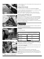
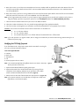
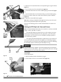
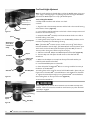
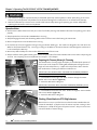
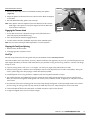
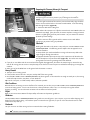
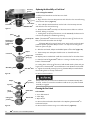
DR® 3-POINT HITCH TRIMMER/MOWER SAFETY & OPERATING INSTRUCTIONS Serial No. Order No. Original Language DR Power Equipment Toll-free phone: 1-800-DR-OWNER (376-9637) Fax: 1-802-877-1213 Website: www.DRpower.com Read and understand this manual and all instructions before operating the DR 3-POINT HITCH TRIMMER/MOWER. Table of Contents Chapter 1: General Safety Rules............................................................................................................................................................ 3 Chapter 2: Setting Up The DR 3-POINT HITCH TRIMMER/MOWER ................................................................................................ 6 Chapter 3: Operating The DR 3-POINT HITCH TRIMMER/MOWER ................................................................................................. 14 Chapter 4: Maintaining The DR 3-POINT HITCH TRIMMER/MOWER.............................................................................................. 17 Chapter 5: Troubleshooting .................................................................................................................................................................. 23 Chapter 6: Parts Lists and Schematic Diagrams .................................................................................................................................. 24 Conventions used in this manual This indicates a hazardous situation, which, if not followed, will result in death or serious injury. This indicates a hazardous situation, which, if not avoided, could result in death or serious injury. This indicates a hazardous situation, which, if not avoided, could result in minor or moderate injury. This information is important in the proper use of your machine. Failure to follow this instruction could result in damage to your machine or property. Serial Number and Order Number A Serial Number is used to identify your machine and is located on the Serial Number Label on your machine. An Order Number is used to check and maintain your order history and is located on the upper left portion of your packing slip. For your convenience and ready reference, enter the Serial Number and Order Number in the space provided on the front cover of this manual. Additional Information and Potential Changes DR Power Equipment reserves the right to discontinue, change, and improve its products at any time without notice or obligation to the purchaser. The descriptions and specifications contained in this manual were in effect at printing. Equipment described within this manual may be optional. Some illustrations may not be applicable to your machine. 2 DR® 3-POINT HITCH TRIMMER/MOWER Chapter 1: General Safety Rules Read this Safety & Operating Instructions manual before you use the DR 3-POINT HITCH TRIMMER/MOWER. Become familiar with the operation and service recommendations to ensure the best performance from your machine. If you have any questions or need assistance, please contact us at www.DRpower.com or call toll-free 1-800-DR-OWNER (376-9637) and one of our Technical Support Representatives will be happy to help you. Labels Your DR 3-POINT HITCH TRIMMER/MOWER carries prominent labels as reminders for its proper and safe use. Shown below are copies of the Safety and Information labels that appear on the equipment. Take a moment to study them and make a note of their location on your DR 3-POINT HITCH TRIMMER/MOWER as you set up and before you operate the unit. Replace damaged or missing safety and information labels immediately. #32440 #13649 #32438 #32442 Tractor Safety Information YOUR DR 3-POINT HITCH TRIMMER/MOWER is driven by a PTO shaft that transfers power from your Tractor. The Tractor and PTO shaft are extremely dangerous and can cause serious injury or death if not used properly. Read and understand all of the Warnings and operating instructions that came with your Tractor and the PTO shaft to protect yourself from severe injury or death. Safety for Children and Pets Tragic accidents can occur if the operator is not alert to the presence of children and pets. Children are often attracted to the machine and the trimming activity. Never assume that children will remain where you last saw them. Always follow these precautions: Keep children and pets out of the working area and under the watchful care of a responsible adult. Be alert and turn the machine off if children or pets enter the work area. Never allow children to operate the DR 3-POINT HITCH TRIMMER/MOWER. Use extra care when approaching blind corners, shrubs, trees, or other objects that may obscure your vision. CONTACT US AT www.DRpower.com 3 Protecting yourself and those around you This is a high-powered machine, with moving parts operating with high energy at high speeds. You must operate the machine safely. Unsafe operation can create a number of hazards for you, as well as anyone else in the nearby area. Always take the following precautions when using this machine: Keep in mind that the operator or user is responsible for accidents or hazards occurring to other people, their property, and themselves. Always wear protective goggles or safety glasses with side shields while trimming to protect your eyes from possible thrown debris. Avoid wearing loose clothing or jewelry, which can catch on the machine’s moving parts. We recommend wearing gloves while using this machine. Be sure your gloves fit properly and do not have loose cuffs or drawstrings. Wear shoes with non-slip treads when using your DR 3-POINT HITCH TRIMMER/MOWER. If you have safety shoes, we recommend wearing them. Do not use the machine while barefoot or wearing sandals with exposed toes or heels. Wear long pants while operating the DR 3-POINT HITCH TRIMMER/MOWER. Use ear protectors or ear plugs rated for at least 20 dba to protect your hearing. Keep bystanders at least 100 feet away from your work area at all times. The tips of the cutting cords on the DR 3-POINT HITCH TRIMMER/MOWER can throw sticks, small stones, gravel, and bits of debris over long distances at great velocity. Do not travel over loose materials such as gravel or mulch with the trimmer head spinning. Doing so could cause personal injury or property damage from thrown objects. Disengage the PTO Shaft to stop the spinning cords and shut off the Tractor engine when another person or pet approaches. Never tamper with safety devices. Check their proper operation regularly. Never operate the machine when under the influence of alcohol, drugs, or medication. Operating the Trimmer/Mower Safely This is a high-powered machine, with moving parts operating with high energy at high speeds. You must operate the machine safely. Unsafe operation can create a number of hazards for you, as well as anyone else in the nearby area. Always take the following precautions when using this machine: Do not have the Trimmer engaged or resting on the ground when backing up. The machine is designed to trim and roll on the Wheel in the forward direction only. Trimming or rolling on the Wheel in the reverse direction could damage the machine and is not covered by the Warranty. Know how to stop the Trimmer quickly by disengaging the PTO Shaft and shutting down the tractor. Never allow people who are unfamiliar with these instructions to use the DR 3-POINT HITCH TRIMMER/MOWER. Allow only responsible individuals who are familiar with these rules of safe operation to use your machine. Do not exceed 2 mph when trimming to allow proper cutting and discharge of material. Do not exceed 7 mph when transporting to prevent damage to the machine. Operating your 3point trimmer with the head misaligned with the ground can result in poor cut quality, pivoting problems, scalping during cutting, wear on your equipment, and damage to the cutting cord Never place your hands, feet, or any part of your body on or under the mower deck in the path of the spinning cords, belt, pulleys, or near the discharge opening while the tractor is running. Keep area of discharge clear of people, animals, buildings, glass, or anything else that will obstruct clear discharge, cause injury, or damage. Your DR 3-POINT HITCH TRIMMER/MOWER is a powerful tool, not a plaything. Exercise extreme caution at all times. The design of your machine is for trimming and mowing grass, weeds, and other growth as specified in this manual. Do not use it for any other purpose. Whenever you leave the operating position to make adjustments, change cords or if you have to remove grass or debris from the underside of the deck, always disengage PTO, shut down the Tractor Engine, remove the Key, wait for all moving parts to come to a complete stop, disconnect the PTO shaft from the Tractor, then wait five minutes before performing any maintenance procedure or inspection on the Trimmer. 4 DR® 3-POINT HITCH TRIMMER/MOWER Operating the Mower Safely (continued) Be mindful of roll over hazards, changes in terrain, slopes, or wet conditions. Use care when backing up. Stop the cutting cords when crossing gravel drives, walks, or roads. Never, under any conditions, remove, bend, cut, fit, weld, or otherwise alter standard parts on the DR 3-POINT HITCH TRIMMER/MOWER. This includes all shields and guards. Modifications to your machine could cause personal injuries and property damage and will void your warranty. If the cutting cords strike a foreign object or if your machine should start making an unusual noise or vibration, disengage PTO, shut down the Tractor Engine, remove the Key, wait for all moving parts to come to a complete stop, disconnect the PTO shaft from the Tractor, then wait five minutes before inspection. Vibration is generally a warning of trouble. Clean and repair and/or replace damaged parts. While using the DR 3-POINT HITCH TRIMMER/MOWER, do not hurry or take things for granted. When in doubt about the equipment or your surroundings, stop the machine and take the time to look things over. Make sure that you have 100% control of the Trimmer at all times. Watch for traffic when mowing near roadways. Use the machine only in daylight. Be cautious when using your DR 3-POINT HITCH TRIMMER/MOWER around fencing, wires, ropes, and hoses. It is possible that these and other debris can become wound around the Cord Head of the machine, potentially damaging the bearings or injuring you. Do not operate the DR 3-POINT HITCH TRIMMER/MOWER on slopes greater than is recommended in your Tractor manual. Keep all nuts and bolts tight and keep the equipment in good operating condition. A Note to All Users No list of warnings and cautions can be all-inclusive. If situations occur that are not covered by this manual, the operator must apply common sense and operate this DR 3-POINT HITCH TRIMMER/MOWER in a safe manner. Contact us at www.DRpower.com or call 1-800-DR-OWNER (376-9637) for assistance. CONTACT US AT www.DRpower.com 5 Chapter 2: Setting Up The DR 3-POINT HITCH TRIMMER/MOWER It may be helpful to familiarize yourself with the controls and features of your DR 3-POINT HITCH TRIMMER/MOWER as shown in Figure 1 before beginning these procedures. If you have any questions at all, please feel free to contact us at www.DRpower.com. DR 3-POINT HITCH TRIMMER/MOWER Controls and Features Upper Hitch Pin 3-Point Hitch Bracket Lower Hitch Pin Gearbox Cutting Cord PTO Shaft Mow-Ball® Pneumatic Caster Wheel Drive Pulley Wheel Height Adjustment Spacers Belt Guide (4 Places) Belt Collar and Pin Trimmer Guard Springback Assembly Belt Tension Pulleys Figure 1 6 DR® 3-POINT HITCH TRIMMER/MOWER Locking Bolt with Wing Nut Specifications Tractor Requirements Drive PTO Speed Number of Trimmer Cords Belt Belt Adjustment Max. Wheel Base (distance from outside to outside of rear wheels) Category 1, 25 to 45 HP Max. Tractor PTO 540 RPM 4 6577BR Gates, 134-3/8˝ L Spring Loaded Idler Pulleys 63" Cutting Height Cutting Width Machine Weight 3 - 7.5 in (3 - 4.5 on the head + 3 in on the wheel in 1/2" increments) 22" 225 Lbs Attaching the 3-Point Bracket to the Tractor Before performing the following procedure, be sure your tractor engine is off, brake is set, and the key removed for safety. 1. Position the 3-Point Bracket at the rear of the Tractor with the Back Plate facing away from the back of the Tractor (Figure 2). The opposite side of the 3-Point Bracket facing the Upper Draft Arm is open. 2. Remove the Linch Pin from the top Hitch Pin and remove the Pin from the 3-Point Bracket. 3. Position the Upper Draft Arm inside the top portion of the 3-Point Bracket and align the Holes. 4. Insert the Top Hitch Pin into the aligned holes and secure with the Linch Pin. Upper Draft Arm Lower Draft Arms Back Plate Lower Hitch Pins 3-Point Bracket Upper Hitch Pin Figure 2 Hitch Pin and Clip 5. Remove the Hitch Pins from the two lower side mounting Pins of the 3Point Bracket. Slide the Lower Draft Arms onto the lower Bracket Pins and secure with the Hitch Pins. 6. Adjust the Lower Draft Arms as needed to center the 3-Point Bracket and then lock the Lower Draft Arms to keep them from swinging side to side. See your Tractor Operator manual for specific instructions to set Draft Arm position. Attaching the Trimmer/Mower to the 3-Point Bracket Locking Ring Figure 3 Mounting Hole Pivot Pin 1. Remove the Hitch Pin with Clip from the Locking Ring and remove the Ring (Figure 3). Note: Leave the Pivot Washer on the Pivot Pin. The bevel should be facing the Trimmer/Mower. 3-Point Bracket 2. Slide the Pivot Pin into the Mounting Hole of the 3-Point Bracket as far as it will go (Figure 4). Pivot Washer (bevel on this side) Figure 4 CONTACT US AT www.DRpower.com 7 3. Secure the Pivot pin to the 3-Point Bracket with the Locking Ring and Hitch Pin with Clip (Figure 5). Hitch Pin with Clip Installing the Wheel Assembly 1. Remove the Hitch Pin and Spacers from the Wheel Shaft (Figure 6). 2. Insert the Wheel Shaft into the Wheel Support from underneath, install the Spacers on top and secure with the Hitch Pin. Note: The Wheel height can be adjusted as needed. This procedure will be discussed later in Chapter 3 “Operating the DR 3-Point Hitch Trimmer/Mower” Pivot Pin Figure 5 Calculating length of PTO Shaft needed Hitch Pin The PTO Shaft provided with your Trimmer is 32" overall compressed length and will work “as is” for most applications. Before you install the PTO Shaft it is good practice to run through the following dimension checks to calculate optimum PTO Shaft length to determine if modifications are needed. Spacers Without the PTO Shaft installed, use the table below to record the dimensions as outlined in the following steps. Wheel Figure 6 The minimum recommended overlap of the tubes at the center of the PTO Shaft should be 6". Using a PTO Shaft with less than 6" overlap may fail and cause machine damage or personal injury. Gearbox Guard Tools Needed: Wheel Support Two 11/16" Wrenches TRACTOR SPLINE SHAFT TO GEARBOX SHAFT MEASUREMENTS Remove Hardware ON GROUND Inches SHAFTS LEVEL Inches FULLY RAISED Inches Loosen Hardware Figure 7 Tractor Spline Shaft Trimmer Gearbox Shaft Note: Install the Locking Bolt as described in the paragraph “INSTALLING THE LOCKING BOLT FOR PARALLEL TRIMMING/MOWING” in the “Preparing the Trimmer/Mower for Trimming” section in Chapter 3. 1. Remove the front Bolt, Washers and Locknut from the Gearbox Guard with two 11/16" Wrenches (Figure 7). 2. Slightly loosen the rear Bolt, Washers and Locknut of the Gearbox Guard with two 11/16" Wrenches. 3. Rotate the Gearbox Guard up away from the Gearbox Shaft. Measure Distance Figure 8 8 DR® 3-POINT HITCH TRIMMER/MOWER 4. Lower the Trimmer all the way to the ground in the operating position (Figure 8). Measure from the end of the Tractor Spline Shaft to the end of the Trimmer Gearbox Shaft and record this dimension in the “ON GROUND” row of the table above. 5. Raise the Trimmer up until the Tractor PTO Spline and Trimmer Gearbox Shaft are parallel with each other. Measure from the end of the Tractor Spline Shaft to the end of the Trimmer Gearbox Shaft and record this dimension in the “SHAFTS LEVEL” row of the table above. 6. Raise the Trimmer up as far as it will go. Measure from the end of the Tractor Spline Shaft to the end of the Trimmer Gearbox Shaft and record this dimension in the “FULLY RAISED” row of the table above. Note: If your longest measurement exceeds 37" you will require a longer PTO Shaft. Do not proceed with installation until you have a longer PTO Shaft. If you have any questions, please visit us at www.DRpower.com or call 1-800-DR-OWNER (376-9637). 7. Take the shortest recorded measurement you wrote in the table and add 2". 8. Take that number and subtract it from 32" (overall compressed length of the supplied PTO Shaft). 9. This final number is the length that you will need to cut off of the PTO Shaft for it to fit properly to your Tractor. EXAMPLE: Let’s assume the shortest center-to-center measurement in the table is 27". 27 + 2 = 29 (step 4 above) 32 – 29 = 3 (step 5 above) You would be required to cut 3" off both halves of the PTO Shaft and 3" off the Guard. Note: If you end up with 0" or a negative number, then no changes are needed until you reach a maximum long measurement of 37" as indicated on previous page. Modifying the PTO Shaft-if required Safety Guard If you have determined in the previous steps that the PTO Shaft is too long for your set up, shorten the Shaft as follows: Tools and Supplies Needed: Hacksaw Bench Vise Tape Measure File General purpose Lithium Grease Bearing Tab Note: Your actual PTO Shaft may look different than the one shown in these steps Figure 9 but the procedures are the same. Safety Guard 1. Separate the PTO Shaft Halves by pulling them apart. 2. Separate the Guards from the PTO Shaft Halves by inserting a flat tip screwdriver into the Bearing Tab Slots as you pull down on the Safety Guard to release the Safety Guard from the Shaft (Figure 9). 3. Measure and cut the ends of both Guards the required amount (Figure 10). Note: If you put the Guards in a vise to hold them, be careful not to clamp it too tight because it could crack the plastic. Cut This End Figure 10 CONTACT US AT www.DRpower.com 9 Shaft Tube 4. Measure and cut each Shaft Tubes to the required length using the hacksaw (Figure 11). 5. File or sand any burrs from the Shaft ends (Figure 12). 6. Grease both Shaft Tubes and under the Bearing Rings of each Shaft (Figure 13). 7. Insert the Shaft Halves into the Guards making sure that the Bearing Ring Slot lines up with the Tab on the inside of the Guards for proper installation (Figure 14). 8. Slide the two PTO Shaft Halves together. Figure 11 Note: When inserting one half of the PTO Shaft to the other you must line up the splines correctly (two pointed splines and one flat spline). Continue to the following section to attach the PTO Shaft to the Tractor and Trimmer. Shaft Tube End Attaching the PTO Shaft to the Tractor and Trimmer Note: The PTO Driveshaft provided with your new machine is sized to fit a standard category 1 PTO (1-3/8" DIA. x 6" Spline). The PTO Spline Shaft on the tractor that is to use this machine must rotate clockwise when viewing the PTO from the rear of the tractor. If the PTO rotates counterclockwise, you must have your tractor modified by installing a gearbox to reverse the direction of rotation. Figure 12 The length of the PTO Driveshaft that is included with your new machine will work in most instances but may need to be modified. See “Calculating Length of PTO Shaft needed” for checking the PTO Shaft length desired and then “Modifying the PTO Shaft if required” instructions if the PTO Shaft is too long. Shaft Tube You must install the Key supplied in the Product Package where the PTO shaft attaches to the Trimmer Gearbox. Failure to install the Key will result in damage to the machine and is not covered under warranty. Bearing Ring Tools Needed: 4mm Allen Wrench Figure 13 1. Open the Gearbox Guard as described on page 8. Bearing Ring Slot 2. Insert the Key into the Trimmer Gearbox Shaft (Figure 15). Guard Tab Gearbox Shaft Key Figure 14 10 DR® 3-POINT HITCH TRIMMER/MOWER Figure 15 3. Align the Key Slot of the PTO Shaft with the Key in the Shaft and slide it onto the Shaft (Figure 16). Note: Do not allow the PTO Shaft to contact the Gearbox. The Gearbox Shaft end should be flush with the inside of the U-Joint. 4. Secure the PTO Shaft by tightening the Set Screw with a 4mm Allen Wrench. Note: If you plan to leave the Trimmer attached to the Tractor for extended periods, apply thread lock to the Set Screw to help secure it in place. Gearbox 5. Push in the Spring Pin at the end of the PTO Shaft and slide it onto the Tractor Spline (Figure 17). When the PTO Shaft is started on the Tractor Spline Shaft, release the Pin and continue to push the PTO Shaft until the Spring Pin locks into the Groove of the Tractor Spline. 6. Attach the Safety Chain of the PTO Shaft around a solid area of the 3-Point Figure 16 Bracket with the Chain ends attached to both ends of the PTO Shaft Guard (Figure 18). Make sure the Chain has enough slack in the full range of the Groove Tractor 3-Point Arm travel. 7. Lower the Gearbox Guard and install the front Bolt, Washers and Locknut with two 11/16" Wrenches (Figure 19). 8. Tighten the rear Gearbox Guard hardware with two 11/16" Wrenches. Installing Trimmer Cords Note: Cutting height adjustments can be made as you learn the trimming characteristics of the machine in the “Operating the DR 3-Point Hitch Trimmer/Mower” in the next Chapter. Always make sure to install all four Trimmer Cords and ensure they are the same length. Not having all four Cords installed and/or at the same length will cause excessive vibration and could damage the machine. 1. Insert the end of a Trimmer Cord into the inlet hole (larger slotted cutout) push it in until the end protrudes out the other side approximately 1/2" (Figure 20). 2. Turn the Cord Head 90 degrees and repeat the installation until all Cords are installed. Note: The Cord can only move through the Cord Head in one direction. To remove it you must pull it from the other side of the Holder (where the 1/2" end is). Running the trimmer without all four cords installed or cords of unequal length can cause excessive vibration and may damage the machine. Set Screw PTO Shaft Tractor Spline Spring Pin PTO Shaft Figure 17 3-Point Bracket Safety Chain PTO Guard Hooks Figure 18 Gearbox Guard Outlet Cord Head Approx. 1/2" Figure 20 Inlet Trimmer Cord Front Hardware Rear Hardware Figure 19 CONTACT US AT www.DRpower.com 11 Cord Head Height Adjustment Screw Driver Note: The Cord Head can be located above or below the Molded Spacer giving you a 1-1/2" range in trimming height. The following steps show moving the Cord Head from below the Molded Spacer to on top of the Molded Spacer. Anti-Wrap Can Molded Spacer 1. Align the hole in the Anti Wrap Canister with the hole in the internal housing at the location shown (Figure 21). Cord Head Figure 21 Tools and Supplies Needed: Phillips head Screwdriver with at least a 6" shank Gloves Mow-Ball® 2. Insert a Philips Head Screwdriver into the hole in the Anti Wrap Canister and the hole in the internal Housing. 3. Rotate the Mow-Ball® Assembly until the Screw Driver slides into a hole in the shaft, locking it into place. Spacer Anti-Wrap Can Molded Spacer (can be above or below Cord Head) 4. Looking down at the top of the Frame, turn the Mow-Ball® clockwise until it unscrews completely from the Bearing Housing. Note: If the Mow-Ball® continues to turn, but does not come off, check that you locked the Screwdriver into the shaft. If the Mow-Ball will not turn by hand a 9/16" Socket can be used on the Bolt (inside the bottom of the Mow-Ball) to loosen it. You may need to clean grass or debris out of the recess first. Adapter Cord Head Adapter Hole (facing up) 5. Slide the Cord Head, Adapter and Molded Spacer off the Shaft (Figure 22). 6. The Anti-Wrap Can and Spacer should remain on the Shaft with the Screwdriver. 7. Make sure the Adapter is inserted into the top of the Cord Head as you install the Cord Head onto the Shaft. 8. Install the Molded Spacer onto the Shaft. 9. Place the head of the Mow-Ball® Bolt so it is sitting inside the hex cavity at the bottom of the Mow-Ball®. Mow-Ball® Mow-Ball® Bolt Figure 22 10. Looking down at the top of the Frame, hold the Bolt Head in place with your finger and turn the Mow-Ball® counterclockwise to start the Bolt into the Shaft. 11. Tighten the assembly securely by turning the Mow-Ball® counterclockwise when looking down on the top of the Frame (Figure 23). 12. Remove the Screwdriver. Always make sure you remove the screwdriver from the head assembly when finished. Failure to remove the screwdriver could cause injury when the head assembly is engaged. Cord Head Molded Spacer Mow-Ball® Figure 23 12 DR® 3-POINT HITCH TRIMMER/MOWER Greasing the Wheel Support Tools needed: Flexible hose grease gun Lithium grease Clean cloth 1. Apply a quality general-purpose lithium grease with a hand-pumped grease gun to each of the Support Grease Fitting (Figure 24). Grease Fitting Support The Assembly and installation of your DR Trimmer/Mower is now complete. Proceed to the next Chapter “Operating the DR 3-POINT HITCH TRIMMER/MOWER” for operating instructions. Figure 24 CONTACT US AT www.DRpower.com 13 Chapter 3: Operating The DR 3-POINT HITCH TRIMMER/MOWER This machine is designed to operate at 540 rpm PTO Shaft speed only! Never operate at a faster speed; doing so can cause serious injury to the operator or bystanders and could cause damage to the machine that is not covered under warranty. Read and understand your Tractor users manual and all Tractor safety Warnings for operating your Tractor safely before operating this DR 3-Point Hitch Trimmer/Mower. Operation Notes See the Owner’s Manual that came with your Tractor for all safety warnings and detailed information for operating your Tractor properly. Always operate the Tractor PTO at 540 RPM when trimming. Always disengage the PTO, lock the Parking Brake and shut off the Tractor when leaving the Tractor Seat. Never transport the Trimmer while the PTO is turning. Do not have the Trimmer engaged or resting on the ground when backing up. The machine is designed to trim and roll on the Wheel in the forward direction only. Trimming or rolling on the Wheel in the reverse direction could damage the machine and is not covered by the Warranty. Remove any debris buildup from the machine before every use of the Trimmer. Always install the Locking Bolt and Wing Nut into the transport holes of the 3-Point Bracket and Trimmer when transporting the Trimmer. See “Preparing the Trimmer/Mower for Transport” in this Chapter. Bolt Head 3-Point Bracket Trimmer Bracket Preparing the Trimmer/Mower for Trimming The characteristics of cutting height and quality is controlled by the position of the Trimmer Cords, location of Locking Bolt, Wheel Spacer arrangement and height of Tractor PTO lift Arms. It takes time and practice to learn what the best combinations of settings for different conditions are. INSTALLING THE LOCKING BOLT FOR PARALLEL TRIMMING/MOWING (terrain that is level with Tractor Wheels) Wing Nut 1. Install the Bolt into the right side “holes” location through the 3-Point Bracket and Trimmer Bracket (Figure 25). Trimming Position 2. Secure the Bolt with the Wing Nut. INSTALLING THE PIVOT BOLT FOR PIVOT TRIMMING/MOWING (terrain that is higher or lower than Tractor Wheels such as ditches) Figure 25 Bolt Head Trimmer Bracket Slot 1. Install the Bolt into the left side “slots” location through the 3-Point Bracket and Trimmer Bracket (Figure 26). 2. Secure the Bolt with the Wing Nut. Checking 3-Point Bracket to PTO Shaft clearance 3-Point Bracket Observe the Trimmer as it is lifted to ensure that the 3-Point Bracket does not contact the PTO Shaft. If they do touch, the Tractor may have a setting to limit the distance it is lifted off the ground to prevent contact. See your Tractor user manual for details of Tractor settings. Pivot Position Wing Nut Figure 26 14 DR® 3-POINT HITCH TRIMMER/MOWER SETTING WHEEL HEIGHT 1. Remove the Hitch Clip and remove the Wheel Assembly with Spacers (Figure 27). Hitch Clip Spacers 2. Adjust the Spacers as desired with some under and some above the Support on the Shaft. 3. Reinstall Wheel Assembly, Spacers and Hitch Clip. Note: More Spacers under the Support will lower the Wheel and set the Trimmer Head Higher. More Spacers on top of the Support will raise the Wheel and set the Trimmer Head Lower. Engaging the Trimmer Head 1. Ensure that the Trimmer is lowered to the ground and all Guards are in place and properly secured before using. Wheel Assembly Support Figure 27 2. Set Tractor throttle at IDLE and engage the PTO. 3. Increase Tractor throttle to the RPM’s required to obtain 540 PTO speed. Note: See your Tractor manual for detailed information on Tractor operation. Stopping the Cords from Spinning 1. Reduce Tractor throttle to IDLE. 2. Disengaging PTO to stop the Trimmer. Cord Tips We ship two (2) thicknesses of Cutting Cord with your DR 3-POINT HITCH TRIMMER/MOWER. The Cords are Blue (175-mil) and Green (155-mil). Because conditions and vegetation vary so much, you should experiment with Cord weights (diameters) to discover what works best for your particular mowing and trimming situations. Here are a few things to keep in mind: If you buy Cutting Cord in rolls, cut it in 13" lengths. Cut them at an angle so they will be easier to install. Soak your Cutting Cord in a bucket of room temperature water for a few days before use to make it more pliable. Storing the Cord in a plastic bag with a damp sponge or cloth will help keep it pliable Cord life depends on trimming conditions. Replace Cords when they become broken or frayed. The smallest diameter Cord capable of cutting the material at hand usually provides the best grass trimming performance. When you need more strength for thicker growth such as berry canes, brambles, thistles, or ragweed, you may want to use the 175-mil Cord. Ease the ends of the Cord into heavy growth and move slowly through thick growth. If there are woody weeds in the material you are cutting, the cutting Cords may wrap around the stalks they cannot cut, and pull away from the Trimmer Head. If the Cord breaks off flush at the Cord Head, use needle nose pliers to pull out the old Cord. UV light can degrade cord, store out of direct sunlight. CONTACT US AT www.DRpower.com 15 Bolt Head 3-Point Bracket Trimmer Bracket Wing Nut Transport Position Figure 28 Preparing the Trimmer/Mower for Transport Always disengage the PTO Shaft before lifting the Trimmer off the ground or transporting the Trimmer to prevent injury or damage to the machine. 1. On the right hand side of the machine (trimmer head side), align the holes of the Trimmer with the holes in the 3-Point Hitch Bracket. Insert the Locking Bolt through the holes (Figure 28). 2. Secure the Bolt with the Wing Nut. Note: Observe the Trimmer as it is lifted to ensure that the 3-Point Bracket does not contact the PTO Shaft. If they do touch, the Tractor may have a setting to limit the distance it is lifted off the ground to prevent contact. See your Tractor user manual for details of Tractor settings. 3. Lift the Trimmer off the ground with the Tractor 3-Point Hitch before transporting to prevent hitting any obstacles. Obstacles Dealing with obstacles in the terrain is easy with your new DR 3-POINT HITCH TRIMMER/MOWER. The following section explains how to approach most common obstacles. Always check your work area before trimming and remove any debris that Optimum Impact might tangle or damage the machine. Zone Label Approach obstacles (fence posts etc) so the impact zone will be within the Figure 29 area of the Optimum Impact Zone Label (Figure 29). This will ensure the best spring action and trimming coverage around the obstacle. If you do run into debris and the Trimmer becomes tangled, disengage PTO, shut down the Tractor Engine, remove the Key, wait for all moving parts to come to a complete stop, then wait five minutes for parts to cool before attempting to untangle the machine. Never Trim or let the Wheel rest on the ground with the Tractor in reverse. Heavy Growth Take your time in heavy growth. If the machine cannot do it all in one pass, overlap half of the cutting swath. Ease the DR 3-POINT HITCH TRIMMER/MOWER into denser growth. If the material is too tough or woody to cut, the Cutting Cords will wrap around it, wear down, or even break off. Tip: Use the “two pass”, one half overlap method, whenever possible. Wet Conditions Because there is no housing to restrict the flow of cut material, you can also use your DR 3-POINT HITCH TRIMMER/MOWER to mow wet or heavy growth. You can use the Trimmer in damp conditions, after a rain, or in the early morning dew without clogging or stalling. You can also mow wet areas such as ditches and around ponds. Slopes Refer to your Tractor Users Manual for slope safety information and operation guidelines. Windrows The DR 3-POINT HITCH TRIMMER/MOWER Cutting Cords cut even tall grass in just one pass, so you can collect clippings and leaves for mulch without raking. The machine ejects cut material to its right side, so you can use it like a lawn broom to make windrows for easy clean-up. Firebreaks Use your Trimmer as a labor saving tool to cut material when creating firebreaks. 16 DR® 3-POINT HITCH TRIMMER/MOWER Chapter 4: Maintaining The DR 3-POINT HITCH TRIMMER/MOWER Regular maintenance is the way to ensure the best performance and long life of your machine. Please refer to this manual for maintenance procedures. Disengage PTO, shut down the Tractor Engine, remove the Key, wait for all moving parts to come to a complete stop, disconnect the PTO shaft from the Tractor, then wait five minutes before performing any maintenance procedure or inspection on the Trimmer. Regular Maintenance Checklist Note: Consider that the service intervals shown are the maximum under normal operating conditions. Increase frequencies under extremely dirty or dusty conditions. See the Owners Manual that came with the Tractor and with the PTO Shaft for Specific Tractor and PTO Shaft maintenance. PROCEDURE Check General Equipment Condition, e.g. Nuts, Bolts, Welds, etc. Replace broken or frayed Cutting Cords. Check the Mow-Ball® and Cord Head for excessive wear. Lubricate PTO Shaft and Wheel Support Grease Fittings BEFORE EACH USE EVERY 8-10 HOURS EVERY 1820 HOURS EVERY 50 HOURS EVERY 100 HOURS Check Belt tension and condition Lubricate PTO Shaft Spline ends and center overlap Replace the Belt Grease pivot bearings and gearbox Maintenance position Many maintenance procedures can be performed easier by positioning the Trimmer in an upright “maintenance” position. This position is for maintenance purposes only. Do not transport or operate the Trimmer in the upright position. Two people are required when setting the Trimmer Body to the maintenance position. One person must steady the Trimmer as the other installs the Bolt. Do not allow the Trimmer Body to go beyond vertical and fall in the opposite direction without the Bolt in place as this could cause injury to you or damage the Trimmer. Never transport the Trimmer in the “Maintenance” position. This could damage the machine and is not covered by the Warranty. 3-Point Bracket 1. Remove the Bolt and Wing Nut that is holding the Trimmer in the trimming operating positions. 2. Lift the Trimmer Body up to a vertical position. With the head of the Bolt facing the Tractor, install the Bolt all the way into the transport hole of the 3Point Bracket (Figure 30). Bolt Figure 30 3. Let the Trimmer Mounting Bracket rest against the Bolt to hold it in the vertical (maintenance) position. CONTACT US AT www.DRpower.com 17 Anti Wrap Canister Replacing the Mow-Ball® or Cord Head Tools and Supplies Needed: Phillips head Screwdriver with at least a 6" shank Gloves Spacer Screw Driver Cord Head Loosen Mow-Ball® Figure 31 4. Align the hole in the Anti Wrap Canister with the hole in the internal housing at the location shown (Figure 31). 5. Insert a Philips Head Screwdriver into the hole in the Anti Wrap Canister and the hole in the internal Housing. 6. Rotate the Mow-Ball® Assembly until the Screw Driver slides into a hole in the shaft, locking it into place. 7. Looking down at the top of the Frame, turn the Mow-Ball® clockwise until it unscrews completely from the Bearing Housing. Spacer Anti-Wrap Can Molded Spacer (can be above or below Cord Head) Note: If the Mow-Ball® continues to turn, but does not come off, check to be sure that you locked the Screwdriver into the shaft. If the Mow-Ball will not turn by hand a 9/16" Socket can be used on the Bolt (inside the bottom of the Mow-Ball) to loosen it. You may need to clean grass or debris out of the recess first. Adapter Cord Head Adapter Hole (facing up) 8. Slide the Cord Head, Adapter and Molded Spacer off the Shaft (Figure 32). 9. The Anti-Wrap Can and Spacer should remain on the Shaft with the Screwdriver. 10. Replace parts as needed and install them onto the shaft in the order shown. 11. Place the head of the Mow-Ball® Bolt so it is sitting in the hex cavity at the bottom of the Mow-Ball®. 12. Looking down at the top of the Frame, hold the Bolt Head in place with your finger and turn the Mow-Ball® counterclockwise to start the Bolt into the Shaft. Mow-Ball® Mow-Ball® Bolt 14. Remove the Screwdriver. Figure 32 Adapter 13. Tighten the assembly securely by turning the Mow-Ball® counterclockwise when looking down on the top of the Frame. Screw (4 Places) Top Plate Always make sure you remove the screwdriver from the head assembly when finished. Failure to remove the screwdriver could cause injury when the head assembly is engaged. Cleaning the Cord Head Spring (4 Places) Locking Cam (4 Places) Middle Plate Bottom Plate Tools Needed: 3mm Allen Wrench Clean Rags Nylon Brush 15. Remove the Cord Head as described in the “Replacing the Mow-Ball® or Cord Head” section. Figure 33 18 DR® 3-POINT HITCH TRIMMER/MOWER 16. Remove the four Screws using a 3mm Allen Wrench (Figure 33). 17. Remove the Springs and Locking Cams from the Middle and Bottom Plates and clean any grass or debris from the Springs and Cams. Locking Cam Plate 18. Clean all Plates using a Nylon Brush and clean Rag to remove all grass and dirt. Spring 19. Inspect the Springs and Cams for damage. If any parts are damaged please call DR Power to order a replacement assembly. 20. Reinstall the Springs and Locking Cams into the middle and bottom Plates (Figure 34). Note: The Bottom Plate has threaded holes and the middle Plate has clearance holes. The Plates must be in the correct order for proper assembly. 21. Assemble the Plates ensuring that they are aligned properly and the Springs and Cams are seated fully into the Plate grooves. The four Screw holes must be aligned and the two halves of the side cutouts should align from Plate to Plate (Figure 35). Spring Locking Cam Figure 34 Outlet Cutout 22. Secure the Cord Head assembly with the four Screws using a 3mm Allen Wrench. 23. Reinstall the Cord Head as described in the “Replacing the Mow-Ball® or Cord Head” section. Always make sure you remove the screwdriver from the head assembly when finished. Failure to remove the screwdriver could cause injury when the head assembly is engaged. Inlet Cutout Figure 35 Belt Guard Replacing the Drive Belt Flange Bolts Use only DR belts on your machine. Do not use hardware store variety belts. Tools needed: 3/8" Wrench Two 9/16" Wrenches 9/16" Deep Socket and Ratchet Flange Bolts Figure 36 1. Remove the eight Flange Bolts from the Belt Guard using a 3/8" Wrench (Figure 36). Belt Guide Pins 2. Lift the Belt Guard from the machine. 3. Remove the two Belt Guide Pins at the head of the Trimmer using two 9/16˝ Wrenches (Figure 37). Note: Observe the orientation of the Belt Guides in the next step. They must be positioned in this way when reinstalled. Belt Guides 4. Loosen the two Belt Guides of the Gearbox Pulley using two 9/16˝ Wrenches and rotate them out of the way. Figure 37 CONTACT US AT www.DRpower.com 19 Belt Tension Spring Flat Groove Idler Pulley 5. Position the 9/16˝ Deep Socket and Ratchet onto the Bolt of the Flat Groove Idler Pulley. The Ratchet Handle and Idler Arm must be aligned for the pivoting of the Arm to work properly (Figure 38). 6. Pull on the Ratchet to rotate the Idler Arm towards the Gearbox Pulley and slide the Belt off the V-Groove Idler Pulley. 7. Allow the Ratchet to return back towards the Spring until the Idler Arm is in line with the Tension Spring. 8. Remove the Belt from the Trimmer Head Pulley and the main Drive Pulley. Idler Arm V-Groove Idler Pulley Figure 38 Belt Guides 9. Install the new DR Drive Belt around the main Drive Pulley and the Trimmer Head Pulley. Ensure that the “V” of the Belt is in the “V” of the Pulleys and there are no twists in the Belt. Note: Make sure the Belt is on the outside of the Frame Mounted Belt Guides and on the inner side of the Flat Groove Idler Pulley (Figure 39). 10. Rotate the Idler Arm towards the Gearbox Pulley with the Ratchet and 9/16˝ Deep Socket (Ratchet Handle in line with the Idler Arm) and position the Belt around the Flat Groove Pulley and then around the V-Groove Pulley (Figure 38). 11. Adjust and tighten the two Belt Guides at the Gearbox Pulley. 12. Install the Belt Guide Pins at the Head of the machine using two 9/16˝ Wrenches. 13. Position the Belt Guard and secure with the eight Flange Bolts using a 3/8" Wrench. Flat Groove Idler Figure 39 20 DR® 3-POINT HITCH TRIMMER/MOWER Grease Fittings Your PTO Shaft was greased at the Factory so it will not need grease until the scheduled maintenance as listed at the beginning of this Chapter. The Wheel Support should have been greased when the machine was assembled and also has a recommended grease maintenance listed. Tools and Supplies needed: U-Joint Grease Fitting Figure 38 Grease Fitting Flexible hose grease gun Lithium grease Clean cloth Note: The U-Joint Grease Fitting is sometimes located on the inside of the Joint. The plastic Collar will need to be unclipped and pushed down to access the Fitting for this type. 1. Wipe all dirt, etc., from the PTO Shaft grease fittings with a clean cloth. 2. Apply no more than three pumps of quality general-purpose lithium grease with a hand-pumped grease gun to each of the two U-Joint Grease Fittings (Figure 38). Support 3. Check the PTO Shaft Set Screw for tightness. If it is not tight then remove it, apply Thread Lock to the threads, then reinstall and tighten the Set Screw. 4. Wipe all dirt, etc., from the Wheel Support fitting with a clean cloth (Figure 39). 5. Apply quality general-purpose lithium grease with a hand-pumped grease gun to the Wheel Support Grease Fitting as needed. Figure 39 Greasing the Gearbox Gearbox Guard The Gearbox is greased at the factory but may require grease to be added after prolonged use.. Tools and Supplies needed: Remove Hardware Figure 40 Access Bolt Loosen Hardware Two 11/16" Wrenches 17mm Wrench Grease gun Mobil, Multipurpose XHP Lithium Grease Clean cloth Note: The Gearbox can hold 550ml. (18.6oz) of Mobil, Multipurpose XHP Lithium Grease. We recommend the Gearbox be completely filled with Grease. 1. Remove the front Bolt, Washers and Locknut from the Gearbox Guard with two 11/16" Wrenches (Figure 40). 2. Slightly loosen the rear Bolt, Washers and Locknut of the Gearbox Guard with two 11/16" Wrenches. 3. Rotate the Gearbox Guard up away from the Gearbox. Gearbox 4. Remove the Access Bolt using a 17mm Wrench (Figure 41). 5. If the Gearbox is not completely full, add Grease as needed to fill. Figure 41 CONTACT US AT www.DRpower.com 21 Replacing the Caster Wheel Tools Needed: Pliers 1. Remove the Hitch Clip with Pliers and remove the Wheel Assembly with Spacers (Figure 42). Hitch Clip Spacers 2. Install the new Wheel Assembly and Spacers. 3. Secure with the Hitch Clip. Check the Tire Pressure Tools Needed: Tire Pressure Gauge Air Compressor Wheel Assembly Figure 42 4. Remove the Valve Stem Protective Cap (Figure 43) and check the tire pressure with a Tire Pressure Gauge. 5. Check what the manufacturers recommended pressure is that is stamped on the side of the Tire. 6. If the pressure reading is too low, add air through the Valve Stem with an air hose. 7. Replace the Valve Stem Protective Cap when finished. Do not over inflate the tires. Inflate to the manufacturers recommended pressure found on the tires. 22 DR® 3-POINT HITCH TRIMMER/MOWER Valve Stem Protective Cap Figure 43 Support Chapter 5: Troubleshooting Most problems are easy to fix. Consult the Troubleshooting Table below for common problems and their solutions. If you continue to experience problems, contact us at www.DRpower.com or call toll-free 1-800-DR-OWNER (376-9637) for support. Disengage PTO, shut down the Tractor Engine, remove the Key, wait for all moving parts to come to a complete stop, disconnect the PTO shaft from the Tractor, then wait five minutes before performing any maintenance procedure or inspection on the Trimmer. Troubleshooting Table SYMPTOM Poor cut quality POSSIBLE CAUSE Cord needs to be replaced. Tractor speed too fast. Scalping Arm or wheel adjustment is off. Check for frame level or height of hydraulic arms on tractor Machine stops cutting Inspect cords Check belt tension/wear Check PTO rotation The Trimmer Head won’t spin or lacks power. Check for proper alignment of the V-Belt. Check it against the “Replacing the Drive Belt” section on page 19. The Belt may be worn or frayed; if so, replace it. If none of the above helps, visit our web site at www.DRPower.com or call 1-800-DROWNER (376-9637) for assistance. CONTACT US AT www.DRpower.com 23 Chapter 6: Parts Lists and Schematic Diagrams Parts List – Head and Wheel Assembly Note: Part numbers listed are available through DR Power Equipment. Ref# Part# Description Ref# Part# Description 1 2 3 4 5 6 7 8 9 10 11 12 13 14 15 16 17 18 19 31117 11465 33350 34325 11152 25311 32447 24538 12376 32232 32207 32442 13649 31098 31101 31301 31099 33432 32200 20 21 22 23 11914 10851 34518 10189 Screw, HWH, 1/4-20 X 3/4˝, Taptite Bolt, HCS FT, 3/8-16 X 3˝, GR5, ZP Bolt, Hex, Flange, 3/8-16 X 1.75˝ Bolt, Hex, Flange, 1/4-20 X 1˝ Bolt, HHCS, 3/8-16 X 1.00˝ Lg. Pin, Cotter, 5/32˝ X 2˝ Guard, Deflector, w/Label Pin, Linch, 3/16˝ X 1-9/16˝ Bushing .766˝ ID 1.0˝ OD Caster, 9˝ X 3.50˝ Wheel Support, Wheel Label, Strike Zone Label, Danger, Blade Can, Anti-Wrap Mow Ball, Hex Bolt Bolt, 3/8-16 X 1˝, GR5, ZP, High HD Spacer, .680˝ X .984˝ X .310˝, ZP Bracket, Mounting, Deflector Guard Pulley, 3.5˝ ED, A-Profile V-Belt, .67˝ Shaft Key, SQ, 3/16˝ X 1˝ Spacer .76˝ ID, 1.50 OD, .50 THK Wheel, 9˝ X 3.50-4 Grease Fitting, 1/4-28, Straight 24 25 26 27 28 29 30 31 32 33 34 35 36 37 38 39 40 41 42 43 44 45 46 Nut, Nylon Lock, Flanged, 3/8-16 Nut, Nylon Lock, 3/8-16, Low Profile Nut, Nylon Lock, Flanged, 1/4-20 Pulley, Idler, B V-Belt, 1.75˝ ID Pulley, Idler, 3l V-Belt, 2.0˝ OD Spindle, Trimmer Washer, Fender 1/4˝ ID X 1˝ OD Washer, Flat, 3/8˝, USS Pin, Belt Guide, 3/8-16, ZP Cover, Belt Mount, Cover Idler Arm Bushing, .386˝ X .623˝ X 1.53˝ Bushing, .384˝ ID .669˝ OD Spacer, Idler Spring, Tension Belt, Drive Spacer, Speed Head Speed Head, 4-Line Adapter, Cord Plate Cord Pack, 13", 24 Pack Label, DR Logo, Silver, 8˝ Label, Pictogram Warning 24 DR® 3-POINT HITCH TRIMMER/MOWER 33333 16413 33331 35047 31092 31096 12697 11239 27660 36414 34420 32198 32206 35048 35051 35018 35045 34385 34387 34403 34383 32443 32440 Schematic – Head and Wheel Assembly 022515 CONTACT US AT www.DRpower.com 25 Parts List – Drive and Pivot Assembly Note: Part numbers listed are available through DR Power Equipment. Ref# Part# 1 2 32374 32205 3 32400 4 5 6 7 8 9 10 11 12 13 14 15 29373 32395 11144 32376 15069 33351 15043 11152 15072 25311 36412 32195 16 17 18 19 20 21 22 23 24 25 26 27 28 29 30 32381 33425 33426 32399 32398 32438 30249 33335 32391 32390 32387 32380 32233 33333 32378 26 Description Bracket, Three Point Bearing, Taper Roller, 25mm ID, 62mm OD, 18.25mm THK Bolt, M8 X 20mm, GR8.8, ZP, W/ Locking Patch Bolt, HCS, 3/8-16 X 5.5˝, GR 5, ZP Bolt, M10 X 180mm, P1.5, GR8.8, ZP Bolt, HHCS, 1/2-13 X 2˝, GR5 Bolt, 3/4-10 X 9.5˝, GR8, YZP Bolt, HHCS, 3/8-16 X 2.5˝ LG. Bolt, Hex, Flange, 3/8-16 X 1.25˝ Bolt, HHCS, 3/8-16 X 1-1/4˝, GR5 Bolt, HHCS, 3/8-16 X 1.00˝ LG. Bushing, 1.385˝ ID X 1.629˝ OD X 1.5˝ L Pin, Cotter, 5/32˝ X 2˝ Frame, w/Labels Gearbox, 1:2.78, 25mm Input & Output Shafts Guard, Gearbox Bracket, Mounting, Gear Box, Left Bracket, Mounting, Gear Box, Right Key, Machine, 8 X 7 X 40mm, Din 6885 A Key, Machine, 8 X 7 X 25mm, Din 6885 A Label, Danger, Gearbox Cover Nut, Nylon Lock, M10-1.5 Nut, Nylon Lock, Flanged, 1/2-13 Nut, Nylon Lock, 1/2-20, Gr5, ZP Nut, Hex, 1/2-20, Gr5, ZP Nut, Wing, 3/4-10, ZP Nut, Hex, 7/8-9, YZP Nut, Slotted, 3/4-10, ZP Nut, Nylon Lock, Flanged, 3/8-16 Pin, PTO Class 1 Draw DR® 3-POINT HITCH TRIMMER/MOWER 31 32 33 34 35 36 37 38 39 24555 24538 32396 32397 32204 32386 32409 32208 32401 40 32201 41 42 43 44 32372 32389 34330 32371 45 46 47 48 49 50 51 52 53 54 55 56 57 58 15138 32388 10179 23499 10181 11239 30250 32379 32234 32408 32439 25453 26568 35046 Ref# Part# Description Pin, Hitch, 3/4˝ X 4-3/4˝ Pin, Linch, 3/16˝ X 1-9/16˝ Pin, Linch, 7/16˝ X 1.5˝, YZP Pin, Hitch, 3/8˝ X 3˝, W/ Cotter Pin Base, Pivot Bracket, Pivot Lock Bracket, Articulating Shaft, Pivot Support PTO Shaft, T20, 1-3/8˝ Z6 & 25mm W/ 8mm Key Yokes Pulley, 9˝ ED, A And B Profile V-Belt, 25 mm Shaft Rod End, Ball Joint, 1/2-20 Thread, Fem Spring, Limiter Spring, Strut Rod, Connecting, 1/2-20 Male RH Thread, 18˝ L Washer, Pivot, 1.375˝ ID, 2.0˝ OD Ring, Locking Washer, Flat, 1/2˝ USS Washer, SAE Flat, 1/2", ZP Washer, Lock, 1/4˝, Split, ZP Washer, Flat, 3/8˝, USS Washer, M10 Washer, Lock, 7/8˝, YZP Spacer, .78˝ ID, 2˝ OD, .18˝ THK Bracket, Strut Label, Branding Shim, 1.58˝ OD, 1.19˝ ID, .050 THK Shims, 1" ID & .38" ID, .16" THK Guide, Belt, Wire Schematic – Drive and Pivot Assembly 022515 CONTACT US AT www.DRpower.com 27 Daily Checklist for the DR 3-POINT HITCH TRIMMER/MOWER To help maintain your DR 3-POINT HITCH TRIMMER/MOWER for optimum performance, we recommend you follow this checklist each time you use your machine. Disengage PTO, shut down the Tractor Engine, remove the Key, wait for all moving parts to come to a complete stop, disconnect the PTO shaft from the Tractor, then wait five minutes before performing any maintenance procedure or inspection on the Trimmer. [ ] CUTTING CORDS: Replace broken or frayed Cords. [ ] MOW-BALL® and Cord Head: Check the Mow-Ball® and Cord Head for wear and replace as needed. [ ] GENERAL CONDITION: Check the general condition of the machine, e.g.; nuts, bolts, welds etc. Disengage PTO, shut down the Tractor Engine, remove the Key, wait for all moving parts to come to a complete stop, disconnect the PTO shaft from the Tractor, then wait five minutes before performing any maintenance procedure or inspection on the Trimmer. End of Season and Storage Lubricate PTO Shaft Grease Fittings. Check the Drive Belt for wear. Replace as needed. Release Drive Belt from Tensioner to relieve Belt stress. Check the general condition of the machine, e.g.; nuts, bolts, welds, etc. Replace parts or tighten Hardware as needed. Store in a dry covered area to protect from moisture. Remove any wrapped weeds from the Mow-Ball® and Wheel Assembly. Clean grass and debris from the top and underneath the Trimmer Frame. 75 MEIGS ROAD, P.O. BOX 25, VERGENNES, VERMONT 05491 ©2015 Country Home Products, Inc. All rights reserved 364161