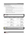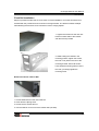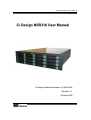
1
Ci Design NSR316 User Manual
15-4126-01A
Ci Design NSR316 User Manual
Ci Design Reference Number: 15-4126-01A
Revision 1.1
October 2009
1
Ci Design NSR316 User Manual
15-4126-01A
Preface
Limited Warranty
Ci DESIGN WARRANTS TO THE ORIGINAL PURCHASER THAT ITS EXTERNAL ENCLOSURE
PRODUCTS INCLUDING THE COMPONENTS THEREIN, SHALL BE FREE FROM DEFECTS
IN MATERIAL AND CRAFTSMANSHIP FOR A LIMITED PERIOD OF THREE (3) YEARS.
SHOULD Ci DESIGN BUNDLE, OFFER, COMBINE OR DISTRIBUTE ANY THIRD PARTY’S
HARDWARE,
PRODUCTS,
MANUFACTURERS
OR
COMPONENTS,
SUPPLIERS
MUST
THE
WARRANTY
APPLY.
ANY
OFFERED
SOFTWARE
BY
SUCH
INSTALLED,
DISTRIBUTED, OR SOLD BY Ci DESIGN IS NOT COVERED BY Ci DESIGN’S LIMITED
WARRANTY AND MUST ONLY REFER TO THE LICENSING AGREEMENT ACCOMPANYING
TO THE SOFTWARE FOR THE TERMS AND CONDITIONS OF USING SUCH SOFTWARE.
ANY OTHER LIMITED WARRANTY PERIOD OFFERED BY Ci DESIGN TO DIFFERENT
PRODUCTS FREE FROM DEFECTS IN MATERIAL AND CRAFTSMANSHIP TO THE
ORIGINAL PURCHASER WILL BE SPECIFIED IN OUR WRITTEN QUOTATION, CONTRACT
OR IN ANY OTHER WRITTEN FORM TO PURCHASER. PURCHASER’S PURCHASE ORDER
TO Ci DESIGN SHALL BE DEEMED IN ACCEPTANCE OF SUCH LIMITED WARRANTY. Ci
DESIGN’S WARRANTY PERIOD STARTS FROM THE DATE OF INVOICE. THESE ARE THE
ONLY WARRANTIES Ci DESIGN OFFERS. Ci DESIGN MAKES NO OTHER WARRANTIES OF
ANY KIND, EXPRESS OR IMPLIED, WRITTEN, ORAL OR STATUTORY, AND EXPRESSLY
DISCLAIMS ANY IMPLIED WARRANTIES, INCLUDING MERCHANTABILITY OR FITNESS FOR
ANY SPECIFIC PURPOSE, REGARDLESS OF ORIGIN. Ci DESIGN DISCLAIMS ANY
EXPRESS OR IMPLIED WARRANTY FOR CLAIMS OF ACTUAL OR ALLEGED PATENT
INFRINGEMENT FOR ANY Ci DESIGN PRODUCT, INCLUDING Ci DESIGN PRODUCTS THAT
ARE COMBINED WITH HARDWARE, SOFTWARE, EQUIPMENT, OR OTHER MATERIALS
NOT FURNISHED BY Ci DESIGN, INCLUDING ANY COVERAGE FOR COMPENSATORY
DAMAGES, PUNITIVE DAMAGES, ATTORNEY FEES, COSTS, CONSEQUENTIAL DAMAGES,
OR OTHER LOSSES, EXPENSES, OR DAMAGES. UNDER NO CIRCUMSTANCE IS Ci
DESIGN LIABLE FOR ANY OF THE FOLLOWING EVEN IF PURCHASER HAS BEEN
INFORMED OF THEIR POSSIBLITY: (a) LOSS OF, DAMAGE TO DATA, (b) INCIDENTAL OR
CONSEQUENTIAL DAMAGES, (c) LOST BUSINESS, REVENUE, PROFIT, GOODWILL OR ANY
ANTICIPATED SAVINGS, (d) THIRD PARTY CLAIMS AGAINST PURCHASER FOR DAMAGES.
2
Ci Design NSR316 User Manual
15-4126-01A
RMA Procedures
Should it be necessary for any reason to return a product to Ci Design, an RMA return
authorization number must be obtained and the following procedures must be followed: (1) Fax or
email a request to a Ci Design representative stating reason for return and provide: purchase
order number, invoice number, Ci Design's part number, and serial number (when applicable). (2)
Purchaser will be faxed or emailed a RMA number and instructions for returning products. (3) The
RMA number must appear on the shipping label of each carton and all shipping documents that
are being returned. RMA product must be received by Ci Design within thirty (30) days after
authorization date. (4) Purchaser must ship returned products "prepaid" unless Ci Design has
agreed in writing to other arrangements. (5) Under all circumstances, any products being returned
to Ci Design must be authorized via Ci Design RMA procedures. (6) Items may be returned for
replacement or credit only. Cash refunds will not be given without specific written authorization
made at the time the RMA is issued by Ci Design. Items being returned must be original Ci
Design products and covered by an applicable warranty period. The authorized returned products
must be packaged in their original packing material with all components included. All returned
items must be in resalable condition, new or no usage. If these requirements are not met, Ci
Design will recover the loss via increased restocking charges or return the products to Purchaser.
If Purchaser is requesting a credit to its account, Purchaser's written request for RMA must be
made within three (3) days after the receipt of the applicable product(s). Upon acceptance of the
returned product(s) by Ci Design, Purchaser's account will be credited, less a 25% "restocking
fee". Ci Design cannot provide cash refunds.
UNDER NORMAL USE, SHOULD THE PRODUCT UNDER WARRANTY FAIL IN MATERIAL
OR CRAFTMANSHIP, Ci DESIGN WILL, AT ITS SOLE DISCRETION, (1) REPAIR AND
RETURN THE PRODUCTS, FREIGHT PREPAID, AND HONOR THE BALANCE OF THE
WARRANTY PERIOD OR (2) REPLACE OR SUBSTITUE THE PRODUCTS, FREIGHT
PREPAID, AND HONOR THE BALANCE OF WARRANTY PERIOD. PRODUCTS THAT HAVE
BEEN DAMAGED THROUGH NEGLIENCE, ACCIDENT, ABUSE, MISAPPLICATION,
MODIFICATION, MISUSE OF THE PURCAHSER OR ITS AGNEST OR DAMAGED THROUGH
SERIVICES, UPGRADES, CHANGE VERSION OR EXPANSIONS PERFORMED BY NOT A Ci
DESIGN’S REPRESENTATIVE OR Ci DESIGN AUTHORIZED SERVICE PROVIDER WILL BE,
AT PURCASHER’S DISCRETION, REPLACED AT PURCHASER’S COST OR RETURN TO
PURCHASER UN-REPAIRD, FREIGHT COLLECT.
3
Ci Design NSR316 User Manual
15-4126-01A
Important Safety Instructions
1. Read all these instructions before installation or connecting the system to the power
outlet.
2. Save these instructions for later use.
3. Following all warnings and instructions marked on the product.
4. Do not use the product near water or block the cooling vent holes.
5. This product should be operated from the type of power source indicated on the marking
label. If you are not sure of the type of power available, consult your dealer or local power
company.
6. Do not attempt to service this product yourself, as opening or removing covers may
expose you to dangerous voltage points or other risk. Refer all servicing to authorized
personnel.
Remarks
Guide to Conventions
The following notational conventions will be used throughout this manual. These blocks are
warnings or cautions and they are used as follows:
CAUTION
This icon indicates the existence of a potential hazard that could result in personal
injury, damage to your equipment, or loss of data if instructions are not observed.
NOTE
This icon indicates important points to consider during the integration process.
Notational Conventions
The following notational conventions will be used in this document.
Dimension will be shown throughout this manual in a U.S. measurement and metric format e.g.
19in. (482.6mm).
4
Ci Design NSR316 User Manual
15-4126-01A
Table of Contents
PREFACE ............................................................................................................................ 2
LIMITED WARRANTY ............................................................................................................. 2
RMA PROCEDURES ............................................................................................................. 3
IMPORTANT SAFETY INSTRUCTIONS ...................................................................................... 4
REMARKS ............................................................................................................................ 4
Guide to Conventions......................................................................................... 4
Notational Conventions...................................................................................... 4
CHAPTER 1 CHASSIS DESCRIPTION ................................................................ 7
OVERVIEW ........................................................................................................................... 7
Items Included ..................................................................................................... 7
Items Needed to Be Purchased Separately...................................................... 8
CHAPTER 2 FEATURE SUMMARY ....................................................................... 9
Chassis Front Panel and Peripheral Bays...................................................... 10
Front Panel Controls and Indicators............................................................... 11
Peripherals......................................................................................................... 12
Hot Swappable Hard Disk Drives .................................................................... 12
Intrusion Switch ................................................................................................ 12
CHAPTER 3 INTEGRATION STEPS.................................................................... 13
BEFORE YOU BEGIN........................................................................................................... 13
Supplies Needed ............................................................................................... 13
Understand Assembly Safety Instructions .................................................... 13
Integration Warnings ........................................................................................ 14
Removing the Top Cover ................................................................................. 15
Changing the Hot Swappable Fan................................................................... 16
Fan Power Board..................................................... Error! Bookmark not defined.
Installing the Server Board .............................................................................. 17
Removing the Hard Disk Drive Tray................................................................ 18
Installing a SAS or SATA Hard Disk Drive ..................................................... 19
Setting Up the Mini-SAS Back Plane............................................................... 20
Installing a Slim Floppy Disk Drive ................................................................. 20
Installing a Slim CD/DVD-ROM Drive .............................................................. 22
Installing the Power Cord................................................................................. 23
CHAPTER 4 INSTALLING THE SYSTEM INTO A RACK ......................... 24
RACK EQUIPMENT PRECAUTIONS ....................................................................................... 24
INSTALLATION SEQUENCE .................................................................................................. 25
Fixed Rail Installation ....................................................................................... 26
APPENDIX A EQUIPMENT LOG ........................................................................... 47
5
Ci Design NSR316 User Manual
15-4126-01A
APPENDIX B CALCULATING POWER USAGE............................................ 48
6
Ci Design NSR316 User Manual
15-4126-01A
Chapter 1
Chassis Description
Overview
The 3U 16-bay NSR 316 rack mountable storage enclosure is designed for storage server system
and supports up to sixteen hot-swappable hard disk drives, available in SATA, SATA II 3 Gb/s or
SAS interface. NSR316 allows support for a SSI 3.0 / 3.5 / 3.6, CEB 1.0, Nehalem / Tylersburg or
AMD Dual Opteron compliant server board 12.0" x 13.0" in size. The chassis is shipped in a
container designed for protection and prevention of damage during shipment. The chassis was
carefully inspected before and during the packing procedure at the factory. Evidence of any
damage to the NSR316 should be reported to the shipper immediately.
NOTE
Electrostatic discharge can damage electronic components. Be sure you are
properly grounded before beginning any procedure.
Items Included
The following components are included with the NSR316 Kits
1. 3U rack mount chassis
2. Sixteen Hard Drive Trays
3. Three Power Cords (U.S.or European version. Number of power cords may vary
depends on power supply used.)
4. One 820W redundant Power Supply (Options are available)
5. One Fan Bracket consisting of four 92mm PWM hot swappable fans for system cooling
6. Fixed mounting bracket
7. One Slim-DVD adaptor
8. One CPU mounting plate
9. One handle set
7
Ci Design NSR316 User Manual
15-4126-01A
Items Needed to Be Purchased Separately
The following components will need to be purchased separately:
1. RAID/NAS controller board/card
2. Server Board
3. Processor to work with respective server board
4. DDR RAM memory DIMMs
5. Hard Disk Drives (HDD)
6. Slim Floppy Disk Drive (FDD)
7. Slim CD-ROM Drive
8. PCI add-in cards
9. CPU heat sink
10. Other peripheral devices
11. Rear fan kit
12. Rear air shroud
13. 2*2.5” boot drive kit
8
Ci Design NSR316 User Manual
15-4126-01A
Chapter 2
Feature Summary
The Ci Design Inc NSR316 R3U chassis provides rugged and reliable housing for Storage and
Server solutions. The chassis is designed to support up to sixteen hot-swappable hard disk drives,
available in SATA, SATA II 3 Gb/s or SAS interface. NSR316 allows support for a SSI 3.0 / 3.5 /
3.6, CEB 1.0, Nehalem / Tylersburg or AMD Dual Opteron compliant server board 12.0" x 13.0" in
size. The chassis can also feature an optional slimline FDD/CD-ROM and one fixed or redundant
PFC power supply.
5
1
6
2
7
3
8
4
1
Controller Card
5
Power Supply
2
Server Board
6
Memory Dimm
3
Slim Floppy Disk Drive
7
92mm How Swappable Fan
4
Hot Swappable HDD Tray (16)
8
Slim DVD Rom Drive
9
Ci Design NSR316 User Manual
15-4126-01A
Chassis Front Panel and Peripheral Bays
To access the system controls and peripherals when a front face plate is installed, unscrew the
two thumbscrews and gently pull it towards you until it is released from the chassis
1
4
2
3
1. Slim Floppy Disk Drive
3. Slim DVD / CD-ROM Drive
2. Front Panel & System Control
4. Hard Drive tray
10
Ci Design NSR316 User Manual
15-4126-01A
Front Panel Controls and Indicators
1
2
3
4
5
6
7
8
9
11
Ci Design NSR316 User Manual
15-4126-01A
Peripherals
The chassis provides a variety of peripheral options that can be purchased separately and added
to the system such as Hard Drive, Floppy Drive, and Slim DVD-ROM:
Hot Swappable Hard Disk Drives
The chassis comes with sixteen drive trays for mounting the SATA, SATAII or SAS hard disk
drives. When a drive fails, the backplane will detect the failure, report it, and power down the
failed drive. As the drives are hot swappable, a support technician can then replace the failed
drive and restore the data without shutting down the system.
Intrusion Switch
The system may include a preinstalled intrusion switch for the access cover that can be
monitored by server management software. When the cover is opened, the switch, located on the
upper right hand corner of the chassis will transmit a signal to the server board where server
management software will process the signal and respond by, for example, powering down the
system or locking the keyboard.
12
Ci Design NSR316 User Manual
15-4126-01A
Chapter 3
Integration Steps
Before You Begin
Before the Ci NSR316 can be installed, you must assemble all hardware components that make
up the system. You may also need to purchase additional peripherals and add-in-cards before the
installation. The following integration steps help guide you through this assembly process and
create your desired system configuration.
NOTE
To maintain and ensure regulation compliance, the fully integrated system should be
tested, certified, and/or documented to illustrate compliance to the regional regulations
and laws for where the product will be sold. The peripherals and add-in cards chosen
for integration should have individual regulatory approvals.
CAUTION
System components must be installed in the order presented in the assembly
instructions. Component damage may result if installed in a different order.
Back up all of your critical data before you proceed or attempt to install the unit.
Supplies Needed
Before beginning, you should make sure you have the following components available:
•
Anti-static wrist strap
•
NSR 316 accessory kit
•
Server board, processors and memory to add to the server board (server version)
•
Optional peripherals and add-in cards
•
Philips screw driver
Understand Assembly Safety Instructions
Before installation, you should make sure you follow certain basic safety precautions
CAUTION
Integration and servicing of this chassis assembly should only be performed by
technically qualified persons.
13
Ci Design NSR316 User Manual
15-4126-01A
Follow these guidelines to meet and maintain safety and product regulatory requirements when
integrating this chassis assembly.
Integration Warnings
These warnings and cautions apply whenever you remove the chassis top cover to access the
internal components.
NOTE
Electrostatic discharge can damage electronic components. Be sure you are properly
grounded before beginning any procedure.
Safety Guidelines
1. Turn off all peripheral devices connected to the server.
2. Turn off the server from the OS or by pressing the power button on the front of the
chassis, then, unplug the AC power cord from the chassis. Disconnect all the peripheral
cables and all network cable connected to the chassis.
3. Provide electrostatic discharge protection by wearing an antistatic wrist strap attached to
ground.
NOTE
1. The power button on the front or rear panel DOES NOT turn off the AC power. You
MUST unplug the AC power cord.
2. Hazardous electrical conditions may be present on power, network, peripheral
cables. Turn off the computer and disconnect all the cables before opening it.
Otherwise, personal injury or component damage may result.
CAUTION
Do NOT open the Power Supply Unit. Hazardous voltages and currents are present
within the power supply. Refer servicing of the power supply to a qualified technician.
14
Ci Design NSR316 User Manual
15-4126-01A
Removing the Top Cover
1.
Unscrew the thumbscrew by turning in the counter-clock-wise direction on the rear of the
top cover. If the thumb screw is too tight, use a Philips screwdriver to loosen it.
2.
Pull the top cover handle backward and slide the whole top cover back until you can lift it
up from the chassis.
3.
Set the top cover away from the immediate working area
15
Ci Design NSR316 User Manual
15-4126-01A
Changing the Hot Swappable Fan
If a fan has failed, the system alarm will beep and the Fan Fault LED will light up. In addition, the
fan board will display a fault LED for the defective fan. Follow these procedures to replace the
failed fan.
1. Pull out the defective fan from
the Fan Bracket as shown.
2. Replace with a functional fan
and install back to the fan bracket.
16
Ci Design NSR316 User Manual
15-4126-01A
Installing the Server Board
1. Install the I/O shield from the inside
of the chassis to the rear panel.
Position one edge so the groove is
outside the rear panel wall and push
until it is seated completely.
Make sure the I/O shield’s edges snap
into place (Refer to your server board
manual for further instruction.)
2. Check the server board mounting
holes location. Place the brass spacer
from the accessories box into the
chassis stud according to the server
board mounting holes location as
shown.
3. With the brass standoffs installed
into the correct location, place the
server board carefully into the chassis
and secure the server board with the
provided #6-32 screws.
17
Ci Design NSR316 User Manual
15-4126-01A
Removing the Hard Disk Drive Tray
Follow the instructions below to remove the Hard Disk Drive Tray from the chassis:
1. Make sure the HDD lock is changed
to unlock position.
1. Pull the retention lever toward
yourself, the lever will become free
form the housing slot.
3. Pull the hard drive tray until it is free
from the chassis.
18
Ci Design NSR316 User Manual
15-4126-01A
Installing a SAS or SATA Hard Disk Drive
1. Remove the hard drive from its
wrapper, and with the drive
circuit-side-down, position the
connector end so that it is facing the
rear of the carrier. Align the holes in the
drive to the holes in the drive mounting
tray. Insert the provided screws into the
tray and secure the drive.
2. Push the drive tray into the drive bay
slot.
(i)
2
3. Secure the drive into the bay:
(ii)
2
(i) Push the right corner of the tray (not
the retention lever) with your thumb
toward the chassis, The retention lever
will automatic shift toward the mounting
tray slot.
(ii) Push the retention lever to lock in
the drive tray.
19
Ci Design NSR316 User Manual
15-4126-01A
Setting Up the Mini-SAS Back Plane
Please refer to the attachment depends on the RAID controller card.
3Ware – Page 28
Areca – Page 34
Adaptec – Page 36
LSI – Page 42
Installing a Slim Floppy Disk Drive
The chassis allows the user to install a slim Floppy, CD or DVD drive. Follow these steps to install
the device:
1.Unscrew the screws of the front top
cover and take the cover apart.
2. Take the slim FDD-drive adapter
PCB from the package.
20
Ci Design NSR316 User Manual
15-4126-01A
3. Mount the slim FDD-drive adapter
PCB into the chassis. Tighten the two
screws that come with the slim
FDD-drive adapter PCB.
4. Place the slim FDD drive into the
chassis. Align the drive mounting holes
to the chassis hooks.
5. Slide the mounting bracket towards
the slim FDD-drive.
Fasten the mounting screw from the
top of the chassis to secure the drive
as shown.
6. Connect the data and power cable
21
Ci Design NSR316 User Manual
15-4126-01A
Installing a Slim CD/DVD-ROM Drive
1. Unscrew the two slim CD-ROM
cover plate mounting screws.
2. Pull out the slim CD-Rom cover plate
and put it back into the accessories
box.
3. Take the slim CD/DVD drive from
the package and the slim CD/DVD
adapter PCB from the accessories box.
4. Mount the slim CD/DVD adapter
PCB into the slim CD/DVD drive.
Tighten the two screws as shown.
5. Place the CD/DVD-drive into the
chassis. Align the CD/DVD drive
mounting holes with the chassis hooks.
6. Slide the other side mounting
bracket towards the CD/DVD-drive as
shown.
7. Fasten the mounting screws from
the top of the chassis to secure the
drive as shown.
8. Connect the mini 4-pin power and
the data cable.
22
Ci Design NSR316 User Manual
15-4126-01A
Installing the Power Cord
If the power cord supplied with the system is not compatible with the AC wall outlet in your region,
get one that meets the following criteria:
•
The cord must be rated for the available AC voltage and have a current rating that it at
least 125% of the current rating of the server.
•
The plug on the power cord that plugs into the wall outlet must be a grounding-type male
plug designed for use in your region.
•
The connector that plugs into the AC receptacle on the power supply must be an IEC 320,
sheet C13, type female connector.
•
In Europe, the cord must be less than 4.5 meters long and it must be flexible <HAR>
(harmonized) or VDE (TUV) certified cordage.
CAUTION
Do not attempt to modify or use the supplied AC power cord if it is not the exact type
required.
NOTE
Please contact your sales representative for order information.
23
Ci Design NSR316 User Manual
15-4126-01A
Chapter 4
Installing the System into a Rack
The NSR316 is a rack mounted chassis. Mounting holes on the front panel are set to RETMA
spacing and will fit into EIA standard equipment rack with 3.5 inches of available vertical space.
Rack Equipment Precautions
This document should be used only as an information source for planning your deployment. Avoid
personal injury and equipment damage by following accepted safety practices.
Floor Loading
CAUTION:
Ensure proper floor support and ensure that the floor loading specifications are adhered
to. Failure to do so may result in physical injury or damage to the equipment and the facility.
Deployment of rack servers, related equipment, and cables exceeds 1800 pounds for a single
42U rack.
External cable weight contributes to overall of the rack installation. Carefully consider cable
weight in all designs
Installation Requirement
CAUTION:
Be aware of the center of gravity and tipping hazards. Installation should be such that a
hazardous stability condition is avoided due to uneven loading. Ci Design recommends that the
rack footings extend 10 inches from the front and back of any rack equipments 22U or higher.
Adequate stabilization measures are required. Customer / user shall review the rack to use
should adequately and safely hold the total weight of the units with all equipments, devices, hard
drives installed. Ensure that the entire rack assembly is properly secured and that all personnel
are trained in proper maintenance and operation procedures. Tipping hazards include personal
injury and death.
Power Input and Grounding
CAUTION:
Ensure your installation has adequate power supply and branch circuit protection.
Check nameplate ratings to assure there is no overloading of supply circuits that could have an
effect on over current protection and supply wiring. Reliable earthing of this equipment must be
maintained. Particular attention should be given to supply connections when connecting to power
strips, rather than direct connections to the branch circuit.
24
Ci Design NSR316 User Manual
15-4126-01A
Thermal Dissipation Requirement
CAUTION:
Thermal dissipation requirements of this equipment deployment mandate minimum
unrestricted airspace of three inches in both the front and the rear. The ambient within the rack
may be higher than room ambient. Installation should be such that the amount of air flow required
for safe operation is not compromised. The maximum temperature for the equipment in this
environment is 122°F (50°C). Consideration should be given to the maximum rated ambient.
Installation Sequence
CAUTION
It is strongly recommended to securely fasten the mounting rack to the floor or wall to
eliminate any possibility of tipping of the rack. This is especially important if you decide
to install several SR 316 chassis’ in the top of the rack.
A brief overview of server installation follows:
1. Select an appropriate site for the rack.
2. Unpack the server and rack mounting hardware.
3. Attach the rack mounting hardware to the rack and to the server enclosure.
4. Mount the server enclosure into the rack.
5. Connect the cables.
6. Turn on and initialize the server.
25
Ci Design NSR316 User Manual
15-4126-01A
Fixed Rail Installation
Skip this procedure if side rails are to be used. For fixed installation, mount the two extend rear
brackets with the provided screws as shown in the figure below. The bracket includes multiple
holes allowing the enclosure to be mounted in racks of varying depths.
1. Tighten the screws into the rear rack
bracket on both sides of the chassis
with the screws provided.
2. While holding the chassis in the
mounting position, tighten the screws,
the nuts or nut plate in the rear of the
mounting bracket. Some rail-frames
have threaded mounting holes; if that is
the case, just simply tighten the
mounting screw.
Remove the Server Chassis Rail
1. Pull the Slide Rail from the outer slide rail.
2. Push down the Spring Latch.
3. Pull the server chassis rail out.
4. Use the fastener to mount it to the chassis side (LH &RH).
26
Ci Design NSR316 User Manual
15-4126-01A
Mount Bracket and Outer Rail to the Rack Cabinet
Assemble Inner Rail to Chassis
1. Place the inner rail to both side of the Chassis (LH & RH)
2. Align the slide mounting holes to the chassis’ mounting holes
3. Fasten the inner rail to the chassis sidewall using the provided screws.
CAUTION
Due to the weight of the chassis with the peripherals installed, lifting the chassis and
attaching it to the cabinet may need additional manpower. If needed, use an
appropriate lifting device.
27
Ci Design NSR316 User Manual
15-4126-01A
B
nN
S
R
niitt
B
ay
ED
DS
Su
up
po
o
nC
De
es
gn
NS
SR
RU
Un
Ba
yL
LE
pp
orrttt o
on
CII D
siig
U
siin
ng
h
3W
a
AM
on
C
arrd
Us
g II²²C
Cw
wiittth
h3
Wa
arre
eA
MC
CC
CC
Co
nttrro
olllle
err C
Ca
d
I. Introduction
This manual will go through the information of using the I²C method with 3Ware Controller Card
( 9650 SE) on CI Design NSR Enclosures using Horizontal Backplane Board 12-6429-02A,
12-6429-05A, 12-6429-06A.
This manual includes the steps of flashing the EPCT onto your 3Ware Controller Card thus
enabling the drive bay Power LED and Status LED functions from the I²C Bus. The drive bay
Activity LED is supported from the P11 of the HDD.
II. Required materials:
1. Cables
P/N: 05-1209-01A
P/N: 05-1187-01A
Figure 1 I²C Cables
2. Software Kit
Download the appropriate 3ware ECPT Code from www.cidesign.com or contact CI
Design Engineer or your 3Ware Rep for software kit compatible with Ci Design chassis.
28
Ci Design NSR316 User Manual
15-4126-01A
III. Instructions for flashing your controller card
1. Download the 3ware ECPT Code and program, use the appropriate esconfig and ECPT
file.
2. Unzip the kit and remember the location.
3. Run the esConfig.exe file.
Example: esconfig –c0 –i xxxx.bin
•
–c# is the controller card port.
•
–i install the CCU onto controller card.
•
xxxx.bin is the name of the ECPT file.
4. After flashing is complete, the system must be restarted.
IV. Settings on Backplane Board
J4
J3
SW1
SW3
Figure 2
J2
J9
J7
J8
SW4
J1
J6
J24
J17
SW2
Backplane Board 12-6429-02A
29
Ci Design NSR316 User Manual
15-4126-01A
HEADER
J6
Shunt-Jumper on pin 9 - 10
SWITCH
SW1
All DIP keys Æ ON
SW3
DIP Key 1
Æ ON
DIP Key 2-6 Æ OFF
SW4
All DIP keys Æ ON
SW2
Table 1
Backplane
Card
SW2 DIP POSITION
Board
Port
1
1
0-3
ON
ON
ON
2
4-7
ON
ON
OFF
3
8-11
ON
OFF
ON
4
12-15
ON
OFF
OFF
5
16-19
OFF
ON
ON
6
20-23
OFF
ON
OFF
2
3
Switch & Header Setting on Backplane Board
V. Connection on Backplane Board
1. Data Cable Connection.
Data Cable Connector
HDD Type
J17
SATA / SAS (primary)
J24
SAS (secondary)
Table 2 Data Cable Connector on the board
30
Ci Design NSR316 User Manual
15-4126-01A
2. I²C Cable Connection
1. The I²C Cable 05-1209-01A must be installed on the First Backplane Board of the unit.
Connect the 4x2 Cable Connector Housing to the J7 Header on the Board (“Red Point”
of Housing Connector to pin #1 J7 Header). The SW2 of this First Board that connect to
PORT 0 of the Card must be set to Binary 0 (ON ON ON).
Figure 3 - I2C cable plugged into backplane
2. The next/ Second Board (if any) must be daisy chained with the First Board using cable
05-1187-01A on J8 and J7. Please be consistent in the way of connecting this cable
(Red wires to Odd pin number). The SW2 of this Second Board that connect to PORT 1
of the Card SW2 must be set to Binary 1 (ON ON OFF).
3. Repeat similar step no.2 if there is additional backplane boards. Refer to Table 1 for
SW2 setting.
Figure 4 Daisy Chain Connection
31
Ci Design NSR316 User Manual
15-4126-01A
3. Power Supply Cable Connection Connect the Power Supply DC Cable to J9 on each
Backplane Board (B/P).
Figure 5 J9 Power Input Pin Out
4. HDD Connection
Engage the HDD on J1, J2, J3, J4.
VII. I²C Cable Connection on Controller Card
1. The I²C 5x2 Cable Connector Housing connects to the 3Ware Card I²C Header (The Red
Point of the Cable Housing Connector to Pin-1 of Card Header).
Red Point
Figure 6 - I²C cable plugged into controller card
32
Ci Design NSR316 User Manual
15-4126-01A
VII. Description of LED codes
The following table describes the drive status LED code.
COLOR
STATUS
Solid Green
Drive OK
Blinking Green
Identify
Black
No Drive
Red and Green
Hot Spare
Blinking Red and Green
Rebuilding
Solid Red
Drive timeout or RAID DCB Error
Blinking Red
SMART threshold exceeded error or ECC error
Blinking and Solid Blue
Drive Activity
Table 3 Drive Bay Status LED Code Description
Drive time-out, DCB error, SMART threshold exceeded, or ECC error will retain across power
cycle (non-volatile).
The exceptions are:
-
ECC error if mapped out by drive (through RAID creation, initialize, write operation),
firmware will report solid green instead of blinking red.
-
DCB error result in solid red across power cycles, unless user creates new array using
the same drive, which firmware will report solid green.
-
SMART error will retain its status through initialization, rebuilding, and array creating by
blinking red.
-
Drive timeout error may or may not retain solid red, if firmware at any point can
communicate with the drive after power cycle, reset, or hard reset.
33
Ci Design NSR316 User Manual
15-4126-01A
B
Ba
ay
yL
LE
ED
DS
Su
up
pp
po
orrtt o
on
nC
CII D
De
es
siig
gn
nN
NS
SR
RU
Un
niitt
U
Ca
arrd
d
Us
siin
ng
gS
SG
GP
PIIO
Ow
wiitth
hA
Arre
ec
ca
aC
Co
on
nttrro
olllle
err C
I. Introduction
This manual will provide the information for Bay LED Support on CI Design NSR Enclosures with
the Horizontal Backplane Board 12-6429-03A, 12-6429-08A using the SGPIO of Areca Controller
Card for enabling the drive bay Activity LED and the Status / Fail LED. The drive bay Power LED
is supported from the backplane board.
II. Required materials:
1. Data Cable SFF8087 with Side-Band.
2. The Backplane Board that has been flashed with the correct Firmware (Blue Point marking
on U10 surface on the board).
III. Settings on Backplane Board
Figure 1 Backplane Board 12-6429-03A
HEADER
J6
Shunt-Jumper on pin 9 - 10
SW1
DIP Key 1
Æ ON
DIP Key 2-5 Æ OFF
SWITCH
SW2
All DIP keys Æ ON
SW3
DIP Key 1
Æ OFF
DIP Key 2-6 Æ ON
Table 1 Switch & Header Setting on Backplane Board
34
Ci Design NSR316 User Manual
15-4126-01A
IV. Connection on Backplane Board
1. Data Cable Connection.
Data Cable Connector
HDD Type
J17
SATA / SAS (primary)
J24
SAS (secondary)
Table 2 Data Cable Connector on the board
2. Power Supply Cable Connection
Connect the Power Supply DC Cable to J9 on each Backplane Board (B/P).
Figure 2 J9 Power Input Pin Out
3. HDD Connection
Engage the HDD on J1, J2, J3, J4.
VI. Installing the cables onto controller card
Using SGPIO, the only cable that needs to be connected to the card is the DATA Cable with
Side-Band.
35
Ci Design NSR316 User Manual
15-4126-01A
B
Ba
ay
yL
LE
ED
DS
Su
up
pp
po
orrtt o
on
nC
CII D
De
es
siig
gn
nN
NS
SR
Ru
un
niitt
U
s
i
n
g
A
d
a
p
t
e
c
C
o
n
t
r
o
l
l
e
r
C
a
r
d
Using Adaptec Controller Card
I. Introduction
This manual will provide the information for bay LED Support on CI Design NSR Enclosures
using the Horizontal Backplane Board 12-6429-04A, 12-6429-09A, 12-6429-10A with Adaptec
Controller Card.
LED Light
Bay L E D
LED Activation Support
Color
Bay Power LED
Green
Backplane Board
Bay HDD Activity LED
Blue
HDD (P11)
Bay Status/ Fail LED
Red
Discrete Cable
Table 1 LED Support with Adaptec Card
II. Bay Status/ Fail LED Support using Discrete Cable
For some Adaptec Cards that do not have the dedicated Status/ Fail LED Header (such as: model
3405, 3805, 31205, 31605), the Bay Fail LED Feature may still be obtained by connecting the Fail
LED Discrete Cable to the Drive Activity LED Header and by setting an option on the Adaptec
RAID Configuration Utility as follow:
1. Turn on Computer, when prompted press Ctrl+A to enter the BIOS-based configuration utility.
2. Select Serial Select Configuration Utility menu.
3. On ‘LED Activity Control’, select option “Disable”.
III. Required Discrete LED Cable
Discrete Cable Part Number
05-3242-03A (600 mm)
Adaptec Card Model
05-3242-01AX (600 mm) /
05-3242-02AX (910 mm)
3405, 3805
√
N/A
N/A
√
√ ( for J3, J1)
√ (for J2)
31205, 31605, 5445
52445
Table 2 LED Discrete Cable for Adaptec
36
Ci Design NSR316 User Manual
15-4126-01A
IV. Settings on Backplane Board
Backplane Board 12-6429-04A
Backplane Board 12-6429-09A
Backplane Board 12-6429-10A
Figure 1 Backplane Board 12-6429
37
Ci Design NSR316 User Manual
15-4126-01A
HEADER
J6
Shunt-Jumper on pin 9-10
SW1
All DIP keys Æ ON
SW3
DIP Key 1-2 Æ OFF
DIP Key 3-6 Æ ON
SW2
All DIP keys Æ ON
SWITCH
Table 3 Switch & Header Setting on Backplane Board
V. Connection on Backplane Board
1. Data Cable Connection.
Data Cable Connector
HDD Type
J17
SATA / SAS (primary)
J24
SAS (secondary)
Table 4 Data Cable Connector on the board
2. LED Discrete Cable Connection
The 4x2-pin Cable Connector must be connected to the Backplane Board on Header J6
with “White Dot” of Cable Connector connects to pin-1 of J6 (Red Wires on lower row).
Figure 2 The 2x4 Cable Housing Connection to Backplane Board
38
Ci Design NSR316 User Manual
15-4126-01A
3. Power Supply Cable Connection
Connect the Power Supply DC Cable to J9 on each Backplane Board (B/P).
Figure 3 J9 Power Input Pin Out
4. HDD Connection
Engage the HDD on J1, J2, J3, J4.
VI. LED Discrete Cable Connection on Adaptec Controller Card
The 8x2 Cable Connector must be connected to the Controller Card on the Status/ Fail LED
Headers with the Red wires are connected to the Anode (A) pin-row (Arrow of Cable Connector to
pin-2 of Header or “White-Dot” of Cable Connector to pin-1 of Header). See Figure 4.
Note: The Location of LED Header on the Card will vary and depend on the Card Model,
but the LED Cable Connection Orientation to the Card LED Headers follows this direction.
White Dot
Cathode
Anode
Figure 4 The 8x2 Cable Housing Connection to Adaptec Card
39
Ci Design NSR316 User Manual
15-4126-01A
VII. Instructions for connecting the Discrete Fail LED Cable
1. Connect the 4X2-pin Cable Connector (labeled F0-F3) to backplane board whose Data Cable
is connected to Port CN0 on the controller card. Refer to Section V for cable connection.
2. Connect the other 4X2-pin Cable Connector (labeled F4-F7) to the next backplane (if any)
whose Data Cable is connected to Port CN1 on the controller card. Refer to Section V for cable
connection.
3. Connect the 8X2-pin Cable Connector of this Discrete Cable (labeled F0-F7) to the Card 8x2
LED Header that is corresponding to the above Data Port (CN0 and CN1).
Refer to section VI
for cable connection. Refer to Section VIII for Location of the Status/ Fail LED Headers on the
Card. If there are more backplane boards and there are more Data Ports available on the Card,
similarly follow step VII.1 – VII.3 for the additional boards:
4. Connect the 4X2-pin Cable Connector (labeled F8-F11) to backplane board whose Data Cable
is connected to its corresponding Port (CN2) on the controller card. Refer to Section V for cable
connection.
5. Connect the other 4X2-pin Cable Connector (labeled F12-F15) to the next backplane (if any)
whose Data Cable is connected to its corresponding Port (CN3) on the controller card. Refer to
Section V for cable connection.
6. Connect the 8X2-pin Cable Connector of this Discrete Cable (labeled F8-F15) to the Card 8x2
LED Header that is corresponding to the above Data Port (CN2 and CN3). Refer to section VI for
cable connection. Refer to Section VIII for Location of the Status/ Fail LED Headers on the Card.
VIII. Location of the Status/ Fail LED Headers on the Card
The Status/ Fail LED Header Location on the Card is indicated with ellipse-mark
1. Adaptec 3805, 3405
For CN0
For CN1
CN0 / J5
CN1 / J3
Figure 5 Adaptec 3805
40
Ci Design NSR316 User Manual
15-4126-01A
2. Adaptec 31605, 31205
For CN3
For CN2
For CN1
For CN0
CN0 / J3
CN1 / J5
CN2 / J18
CN3 / J14
Figure 6 Adaptec 31605
3.
Adaptec 5445
For CN0
CN0
Figure 7 Adaptec 5445
41
Ci Design NSR316 User Manual
15-4126-01A
B
niitt
Ba
ay
yL
LE
ED
DS
Su
up
pp
po
orrtt o
on
nC
CII D
De
es
siig
gn
nN
NS
SR
RU
Un
W
Wiitth
hL
LS
SII L
Lo
og
giic
cC
Co
on
nttrro
olllle
err C
Ca
arrd
d
I. Introduction
The following instructions will provide information to support the Bay LED on CI Design NSR Unit
using the horizontal Backplane Board 12-6429-04A with LSI Logic Controller Card.
Bay L E D
LED Activation Support
Bay Power LED
Backplane Board
Bay HDD Activity LED
HDD (P11)
Bay Status/ Fail LED
Discrete Cable
Table 1 LED Support with LSI Logic Card
II. Required LED Cable:
LED CABLE PART NUMBER
LSI CONTROLLER CARD
MegaRAID SAS/SATA 84016E
MegaRAID SAS/SATA 8708ELP
L 600 mm
L 910 mm
05-3243-03A
05-3243-04A
05-3243-01A
05-3243-02A
Table 2 LED Discrete Cable
III. Settings on Backplane Board
J3
J4
SW1
SW3
J1
J2
J9
J7
J8
J6
J 24
J 17
Figure 1 Backplane Board 12-6429
42
SW2
Ci Design NSR316 User Manual
15-4126-01A
HEADER
JP 6
Shunt Jumper on pin 9 -10
SW1
All DIP keys Æ ON
SW3
DIP Key 1-2 Æ OFF
SWITCH
DIP Key 3-6 Æ ON
SW4
All DIP keys Æ OFF
SW2
All DIP keys Æ ON
Table 3 Switch & Header Setting on Backplane Board
IV. Connection on Backplane Board
1. Data Cable Connection.
Data Cable Connector
HDD Type
J17
SATA / SAS (primary)
J24
SAS (secondary)
Table 4 Data Cable Connector on the board
2. LED Discrete Cable Connection
The 4-pin Cable Connector of the LED Discrete Cable must be connected to the Backplane
Board on the Upper Row of J6 (Arrow of Cable Connector to pin-1 of J6) as shown on
Figure 2.
Arrow
Figure 2 The 4-pin LED Cable Connection to the Backplane Board
43
Ci Design NSR316 User Manual
15-4126-01A
3. Power Supply Cable Connection
Connect the Power Supply DC Cable to J9 on each Backplane Board (B/P).
Figure 3 J9 Power Input Pin Out
4. HDD Connection
Engage the HDD on J1, J2, J3, J4.
V. LED Discrete Cable Connection on Controller Card
The 8-pin Cable Connector must be connected to the LSI Card on the 8x2 Fault LED Header
on Cathode Pins as shown on Figure 3.
8-pin LED Cable
Cathode pins
Connection Position
Figure 3 Connection of the 8-pin LED Cable Connector to LSI Card
The Location and Cable Connection/ Orientation to this LED Header depend on the LSI
Card Model. Refer to Section VII for details.
44
Ci Design NSR316 User Manual
15-4126-01A
VI. Instructions for connecting the discrete Fail LED cable
1. Connect the 4-pin Cable Connector of the LED Cable Assembly (Label F0-F3) to the First
Backplane Board. The Data Cable connects to the Data Ports 0-3 on LSI Card. Refer to
IV.2 for the Backplane LED Cable Connection.
2. Connect the other 4-pin Cable Connector (Label F4-F7) to the Second Backplane Board, if
any, whose Data Cable connects to the Data Ports 4-7 on LSI Card. Refer to IV.2 for the
Backplane LED Cable Connection.
3. Connect the 8-pin Cable Connector of this LED Cable Assembly (Label 0-7) to the Card on
the 8x2 Fault LED Header Location that is corresponding to the Data Ports 0 - 7. Refer to
Section V for the LED Cable Connection on the Card.
For more backplane boards on more location of Data Ports on the Card, similarly follow step
VI1- VI3:
4. Connect the 4-pin Cable Connector of the LED Cable Assembly (Label F8-F11) to the Third
Backplane Board whose Data Cable connects to the Data Ports 8-11 on LSI Card. Refer to
IV.2 for the Backplane LED Cable Connection.
5. Connect the other 4-pin Cable Connector (Label F12-F15) to the Forth Backplane Board
whose Data Cable connects to the Data Ports 12-15 on LSI Card. Refer to IV.2 for the
Backplane LED Cable Connection.
6. Connect the 8-pin Cable Connector of this LED Cable Assembly (Label 8-15) to the Card on
the 8x2 Fault LED Header Location that is corresponding to the Data Ports 8 -15. Refer to
Section V for the LED Cable Connection on the Card.
45
Ci Design NSR316 User Manual
15-4126-01A
VII. LED Cable Connection and Orientation on LSI Card
The Fault LED Header is highlighted on the drawing.
1.
LSI 84016E
LED Cable F0-F7 connects to J14 Header on the Card, Arrow of Cable Connector to pin-2 of Header.
LED Cable F8-F15 connects to J3 Header on the Card, Arrow of Cable Connector to pin-2 of Header.
Arrow to pin-2
Of J14 Header
For
For
Port 0-3
Port 4-7
Figure 4 LSI SAS/SATA 84016E
2.
LSI 8708ELP
LED Cable F0-F7 connects to J5 Header on the Card, Arrow of Cable Connector to pin-16 of Header.
Arrow to pin-16
For Port 4-7
Of J5 Header
For Port 0-3
Figure 5
LSI SAS/SATA 8708ELP
46
Ci Design NSR316 User Manual
15-4126-01A
Appendix A
Equipment Log
Use the following worksheet provided below to record information about your system.
Item
Manufacture Name
and Model Number
Serial Number
Date Installed
Chassis
Server Board
Processor 1
Processor 2
Memory
Video Card
Hard Disk 1
Hard Disk 2
Hard Disk 3
Hard Disk 4
Hard Disk 5
Hard Disk 6
Hard Disk 7
Hard Disk 8
Hard Disk 9
Hard Disk 10
Hard Disk 11
Hard Disk 12
Hard Disk 13
Hard Disk 14
Hard Disk 15
Hard Disk 16
Slim CD-ROM
Slim FDD
Controller Card
47
Ci Design NSR316 User Manual
15-4126-01A
Appendix B
Calculating Power Usage
Calculating DC Current Usage
List all current consumption into the appropriate voltage level for each device and calculate the
total current on each voltage level.
Current (Maximum) at voltage level:
Device
(+5Vsb)
(+3.3V)
(+5V)
(+12V)
(-5V)
(-12V)
0.5A
0.8A
Server Board
Processor(s)
Total Memory
Front Panel LEDs
0.10
SCSI/ATA/FC backplane
1.00
Slim Floppy Disk Drive
Slim CD-Rom Drive
Total Hard Disk Drives
Add-in-Card 1
Add-in-Card 2
Add-in-Card 3
Cooling Fans* , 4x80mm
3.00
Total Current
Maximum Ratings**
(for comparison)
2.0A
28A
35A
28A
* Typical 7500rpm 40mm x40mm fan. Higher speed fans required more current, refer to the fan label for power
consumption information.
** Typical 400W 1U Power Supply, refer to the PSU label for power output characteristics information.
Calculating Total Power Usage
From the worksheet above, enter the total current for each column and then multiply the voltage
by the total current to get the total wattage for each voltage level. Add all the wattages up and find
the total power usage.
Voltage level and total
current
+5 Vsb x (
)A =
(+ 3.3V) x (
(+ 5 V) x (
(+ 12 V) x (
(-5 V) x (
(-12VV) x (
Total Watts for each voltage level
)A =
)A =
)A =
)A =
)A =
Total Combined Wattage
48
Ci Design NSR316 User Manual
15-4126-01A
Disclaimer
Information in this document is provided in connection with Ci Design products. No license, express or implied, by
estoppel or otherwise, to any intellectual property rights is granted by this document. In no event will Ci Design be liable to
the purchaser, or to any user of the Ci Design product, for any damages, expenses, lost revenues, lost savings, lost
profits, or any other incidental or consequential damages arising from the purchase, use or inability to use the Ci Design
product, even if Ci Design has been advised of the possibility of such damages.
Ci Design may make changes to specifications and product descriptions at any time, without notice.
Intel and Intel Pentium are registered trademarks of Intel Corporation, other trademarks or trade names mentioned herein
are hereby acknowledged as being the property of their respective companies.
Copyright © 2009, Ci Design Inc. All Rights Reserved.
49