1
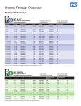
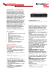
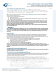
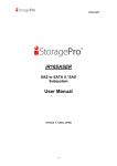
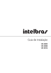
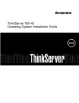
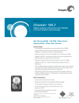
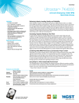
15-4157-01A
Ci Design NSRE424, NSR436 User Manual
Ci Design Reference Number: 15-4157-01A
Revision 1.0
February 2013
Ci Design and iStoragePro are registered trademarks of Commercial and Industrial Design Co., Inc. All rights reserved. All
other trademarks, trade names or company names referenced herein are used for identification purposes only, and are
the property of their respective owners. All dates, specifications, features, and figures specified on this page are
introductory and based on ideal conditions, may vary based on configuration, and are subject to change without notice.
20130214
1
15-4157-01A
Preface
Limited Warranty
Ci DESIGN WARRANTS TO THE ORIGINAL PURCHASER THAT ITS EXTERNAL ENCLOSURE
PRODUCTS INCLUDING THE COMPONENTS THEREIN, SHALL BE FREE FROM DEFECTS IN MATERIAL
AND CRAFTSMANSHIP FOR A LIMITED PERIOD OF THREE (3) YEARS. SHOULD Ci DESIGN BUNDLE,
OFFER, COMBINE OR DISTRIBUTE ANY THIRD PARTY’S HARDWARE, PRODUCTS, COMPONENTS,
THE WARRANTY OFFERED BY SUCH MANUFACTURERS OR SUPPLIERS MUST APPLY. ANY
SOFTWARE INSTALLED, DISTRIBUTED, OR SOLD BY Ci DESIGN IS NOT COVERED BY Ci DESIGN’S
LIMITED WARRANTY AND MUST ONLY REFER TO THE LICENSING AGREEMENT ACCOMPANYING TO
THE SOFTWARE FOR THE TERMS AND CONDITIONS OF USING SUCH SOFTWARE. ANY OTHER
LIMITED WARRANTY PERIOD OFFERED BY Ci DESIGN TO DIFFERENT PRODUCTS FREE FROM
DEFECTS IN MATERIAL AND CRAFTSMANSHIP TO THE ORIGINAL PURCHASER WILL BE SPECIFIED
IN OUR WRITTEN QUOTATION, CONTRACT OR IN ANY OTHER WRITTEN FORM TO PURCHASER.
PURCHASER’S PURCHASE ORDER TO Ci DESIGN SHALL BE DEEMED IN ACCEPTANCE OF SUCH
LIMITED WARRANTY. Ci DESIGN’S WARRANTY PERIOD STARTS FROM THE DATE OF INVOICE.
THESE ARE THE ONLY WARRANTIES Ci DESIGN OFFERS. Ci DESIGN MAKES NO OTHER
WARRANTIES OF ANY KIND, EXPRESS OR IMPLIED, WRITTEN, ORAL OR STATUTORY, AND
EXPRESSLY DISCLAIMS ANY IMPLIED WARRANTIES, INCLUDING MERCHANTABILITY OR FITNESS
FOR ANY SPECIFIC PURPOSE, REGARDLESS OF ORIGIN. Ci DESIGN DISCLAIMS ANY EXPRESS OR
IMPLIED WARRANTY FOR CLAIMS OF ACTUAL OR ALLEGED PATENT INFRINGEMENT FOR ANY Ci
DESIGN PRODUCT, INCLUDING Ci DESIGN PRODUCTS THAT ARE COMBINED WITH HARDWARE,
SOFTWARE, EQUIPMENT, OR OTHER MATERIALS NOT FURNISHED BY Ci DESIGN, INCLUDING ANY
COVERAGE FOR COMPENSATORY DAMAGES, PUNITIVE DAMAGES, ATTORNEY FEES, COSTS,
CONSEQUENTIAL DAMAGES, OR OTHER LOSSES, EXPENSES, OR DAMAGES. UNDER NO
CIRCUMSTANCE IS Ci DESIGN LIABLE FOR ANY OF THE FOLLOWING EVEN IF PURCHASER HAS
BEEN INFORMED OF THEIR POSSIBLITY: (a) LOSS OF, DAMAGE TO DATA, (b) INCIDENTAL OR
CONSEQUENTIAL DAMAGES, (c) LOST BUSINESS, REVENUE, PROFIT, GOODWILL OR ANY
ANTICIPATED SAVINGS, (d) THIRD PARTY CLAIMS AGAINST PURCHASER FOR DAMAGES.
Ci Design and iStoragePro are registered trademarks of Commercial and Industrial Design Co., Inc. All rights reserved. All
other trademarks, trade names or company names referenced herein are used for identification purposes only, and are
the property of their respective owners. All dates, specifications, features, and figures specified on this page are
introductory and based on ideal conditions, may vary based on configuration, and are subject to change without notice.
20130214
2
15-4157-01A
RMA Procedures
Should it be necessary for any reason to return a product to Ci Design, an RMA return authorization number
must be obtained and the following procedures must be followed: (1) Fax or email a request to a Ci Design
representative stating reason for return and provide: purchase order number, invoice number, Ci Design's
part number, and serial number (when applicable). (2) Purchaser will be faxed or emailed a RMA number and
instructions for returning products. (3) The RMA number must appear on the shipping label of each carton
and all shipping documents that are being returned. RMA product must be received by Ci Design within thirty
(30) days after authorization date. (4) Purchaser must ship returned products "prepaid" unless Ci Design has
agreed in writing to other arrangements. (5) Under all circumstances, any products being returned to Ci
Design must be authorized via Ci Design RMA procedures. (6) Items may be returned for replacement or
credit only. Cash refunds will not be given without specific written authorization made at the time the RMA is
issued by Ci Design. Items being returned must be original Ci Design products and covered by an applicable
warranty period. The authorized returned products must be packaged in their original packing material with all
components included. All returned items must be in resalable condition, new or no usage. If these
requirements are not met, Ci Design will recover the loss via increased restocking charges or return the
products to Purchaser. If Purchaser is requesting a credit to its account, Purchaser's written request for RMA
must be made within three (3) days after the receipt of the applicable product(s). Upon acceptance of the
returned product(s) by Ci Design, Purchaser's account will be credited, less a 25% "restocking fee". Ci Design
cannot provide cash refunds.
UNDER NORMAL USE, SHOULD THE PRODUCT UNDER WARRANTY FAIL IN MATERIAL OR
CRAFTMANSHIP, Ci DESIGN WILL, AT ITS SOLE DISCRETION, (1) REPAIR AND RETURN THE
PRODUCTS, FREIGHT PREPAID, AND HONOR THE BALANCE OF THE WARRANTY PERIOD OR (2)
REPLACE OR SUBSTITUE THE PRODUCTS, FREIGHT PREPAID, AND HONOR THE BALANCE OF
WARRANTY PERIOD. PRODUCTS THAT HAVE BEEN DAMAGED THROUGH NEGLIENCE, ACCIDENT,
ABUSE, MISAPPLICATION, MODIFICATION, MISUSE OF THE PURCAHSER OR ITS AGNEST OR
DAMAGED THROUGH SERIVICES, UPGRADES, CHANGE VERSION OR EXPANSIONS PERFORMED
BY NOT A Ci DESIGN’S REPRESENTATIVE OR Ci DESIGN AUTHORIZED SERVICE PROVIDER WILL
BE, AT PURCASHER’S DISCRETION, REPLACED AT PURCHASER’S COST OR RETURN TO
PURCHASER UN-REPAIRD, FREIGHT COLLECT.
Ci Design and iStoragePro are registered trademarks of Commercial and Industrial Design Co., Inc. All rights reserved. All
other trademarks, trade names or company names referenced herein are used for identification purposes only, and are
the property of their respective owners. All dates, specifications, features, and figures specified on this page are
introductory and based on ideal conditions, may vary based on configuration, and are subject to change without notice.
20130214
3
15-4157-01A
Important Safety Instructions
1. Read all these instructions before installation or connecting the system to the power outlet.
2. Save these instructions for later use.
3. Following all warnings and instructions marked on the product.
4. Do not use the product near water or block the cooling vent holes.
5. This product should be operated from the type of power source indicated on the marking label. If you
are not sure of the type of power available, consult your dealer or local power company.
6. Do not attempt to service this product yourself, as opening or removing covers may expose you to
dangerous voltage points or other risk. Refer all servicing to authorized personnel.
Remarks
Guide to Conventions
The following notational conventions will be used throughout this manual. These blocks are warnings or
cautions and they are used as follows:
CAUTION
This icon indicates the existence of a potential hazard that could result in personal injury, damage
to your equipment, or loss of data if instructions are not observed.
NOTE
This icon indicates important points to consider during the integration process.
Notational Conventions
The following notational conventions will be used in this document.
Dimension will be shown throughout this manual in a U.S. measurement and metric format e.g. 19in.
(482.6mm).
Ci Design and iStoragePro are registered trademarks of Commercial and Industrial Design Co., Inc. All rights reserved. All
other trademarks, trade names or company names referenced herein are used for identification purposes only, and are
the property of their respective owners. All dates, specifications, features, and figures specified on this page are
introductory and based on ideal conditions, may vary based on configuration, and are subject to change without notice.
20130214
4
15-4157-01A
Table of contents
PREFACE...................................................................................................................................................................... 2
LIMITED WARRANTY ......................................................................................................................................................... 2
RMA PROCEDURES ........................................................................................................................................................... 3
IMPORTANT SAFETY INSTRUCTIONS .................................................................................................................................. 4
REMARKS .......................................................................................................................................................................... 4
Guide to Conventions ............................................................................................................................................ 4
Notational Conventions............................................................................................................................................... 4
CHAPTER 1 CHASSIS DESCRIPTION .................................................................................................... 8
OVERVIEW ....................................................................................................................................................................... 8
CHAPTER 2 FEATURE SUMMARY .......................................................................................................... 9
KEY FEATURES .................................................................................................................................................................. 9
ENJOY A RANGE OF BENEFITS ........................................................................................................................................... 9
2.1 CHASSIS FRONT PANEL AND PERIPHERAL BAYS ..................................................................................................... 10
2.1.1 USB Port ........................................................................................................................................................... 10
2.1.2 PSU Indicator ................................................................................................................................................... 10
2.1.3 Display Panel.................................................................................................................................................... 11
2.1.4 Hot Swappable Hard Disk Drives .................................................................................................................... 11
2.1.5 Hard drive tray LED functions ........................................................................................................................ 11
2.1.6 Unlock/ Lock functions .................................................................................................................................... 12
2.2 CHASSIS REAR AND PERIPHERAL BAYS ................................................................................................................... 12
Ci Design and iStoragePro are registered trademarks of Commercial and Industrial Design Co., Inc. All rights reserved. All
other trademarks, trade names or company names referenced herein are used for identification purposes only, and are
the property of their respective owners. All dates, specifications, features, and figures specified on this page are
introductory and based on ideal conditions, may vary based on configuration, and are subject to change without notice.
20130214
5
15-4157-01A
2.2.1 NSRE424 rear view .......................................................................................................................................... 12
2.2.2 NSRE436 rear view .......................................................................................................................................... 13
2.3 INSIDE THE CHASSIS ................................................................................................................................................. 14
2.3.1 NSRE424 & NSRE436 top view....................................................................................................................... 14
2.3.2 Removable motherboard tray ........................................................................................................................... 15
2.3.3 2.5” Hard drive tray......................................................................................................................................... 15
2.3.4 NSRE424 & NSRE436 backplane and daughter board ................................................................................. 15
2.3.4.1 24 Bays Backplane (12-6511-02A)..............................................................................................................................17
2.3.4.2 12 Bays Backplane (12-6511-01A)..............................................................................................................................17
2.3.4.3 Daughter Board (12-6511-03A) ..................................................................................................................................18
CHAPTER 3 INTEGRATION STEPS ....................................................................................................... 20
BEFORE YOU BEGIN ...................................................................................................................................................... 20
Supplies Needed......................................................................................................................................................... 20
Understand Assembly Safety Instructions ................................................................................................................ 20
Integration Warnings ................................................................................................................................................ 21
Removing the Top Cover ........................................................................................................................................... 22
Hot Swappable Fan ................................................................................................................................................... 22
Fans connection: ........................................................................................................................................................................22
Replacing the defective fan........................................................................................................................................................23
Installing the Server Board ....................................................................................................................................... 23
Removing the Hard Disk Drive Tray ........................................................................................................................ 25
Installing a 3.5” SAS or SATA Hard Disk Drive ...................................................................................................... 26
Installing the 2.5” Hard drive ................................................................................................................................... 28
Ci Design and iStoragePro are registered trademarks of Commercial and Industrial Design Co., Inc. All rights reserved. All
other trademarks, trade names or company names referenced herein are used for identification purposes only, and are
the property of their respective owners. All dates, specifications, features, and figures specified on this page are
introductory and based on ideal conditions, may vary based on configuration, and are subject to change without notice.
20130214
6
15-4157-01A
Connecting NSRE424/NSRE426 to HBA/ Raid controller...................................................................................... 28
Daisy Chain the daughter board ............................................................................................................................... 29
CHAPTER 4 SLIDE RAIL INSTALLATION........................................................................................ 30
APPENDIX ....................................................................................................................................................................... 39
A.1 HARD DRIVE COMPATIBILITY LIST ............................................................................................................................. 39
A.2 RAID CONTROLLER COMPATIBILITY LIST ................................................................................................................... 39
FAQ................................................................................................................................................................................ 40
Ci Design and iStoragePro are registered trademarks of Commercial and Industrial Design Co., Inc. All rights reserved. All
other trademarks, trade names or company names referenced herein are used for identification purposes only, and are
the property of their respective owners. All dates, specifications, features, and figures specified on this page are
introductory and based on ideal conditions, may vary based on configuration, and are subject to change without notice.
20130214
7
15-4157-01A
Chapter 1
Chassis Description
Overview
The 4U 24-bay (NSRE424)/ 36-bay (NSRE436) rack mountable storage enclosure is designed for storage
server system and supports up to twenty-four/ thirty-six hot-swappable hard disk drives, available in SATA III
6 Gb/s or SAS interface. The chassis is shipped in a container designed for protection and prevention of
damage during shipment. The chassis was carefully inspected before and during the packing procedure at the
factory. Evidence of any damage to the NSRE424/ NSRE436 should be reported to the shipper immediately.
NOTE
Electrostatic discharge can damage electronic components. Be sure you are
properly grounded before beginning any procedure.
Ci Design and iStoragePro are registered trademarks of Commercial and Industrial Design Co., Inc. All rights reserved. All
other trademarks, trade names or company names referenced herein are used for identification purposes only, and are
the property of their respective owners. All dates, specifications, features, and figures specified on this page are
introductory and based on ideal conditions, may vary based on configuration, and are subject to change without notice.
20130214
8
15-4157-01A
Chapter 2
Feature Summary
Ci Design proudly presents this expander storage / server rack mountable enclosure 4U NSRE424 24-Bay /
NSRE436 36-bay Expander Solution. Based on the good design of NSR series, NSRE is built in with most
updated expander boards to handle high volume data response but save cost on internal cables and
controller cards. This model supports redundant power supplies, hot-swap hard drives, hot-swap fans and
Dual / Quad Intel® Xeon™ and AMD® Opteron™ server boards.
Key Features
•
•
•
•
•
•
•
•
•
•
•
•
SAS, SATA 6.0 Gb/s and SSD
Server board footprint compatibility
Fan speed controlled by motherboard
Maximum open area on drive trays
Drive tray with locking feature
Increased EMI/EDS features
Hot swap fans mounted on rubber screws
Two USB connections on front panel
Front panel power supply fail LED - Redundant power
Logo indent on drive tray
Thick gauge sheet metal
High confidence 3 year limited warranty
Enjoy A Range of Benefits
•
•
•
•
•
•
•
•
•
•
•
•
•
Supports a range of drive options in one chassis
Lowers down time due to OS drive failure
Supports 12"x13" form factor motherboards
Lower noise and energy costs
Increased airflow maximizes drive MTBF
Designed to meet FCC class A at higher emissions frequencies
Lowers noise and dampens vibration
Easy access and maintenance at front panel
Clearly visible indicator eliminates guesswork
Customize with company logo or disk ID labeling
Better rigidity and protection of valuable electronics
Future-proof design to support tomorrow's faster throughput
Worry free support from 30 year old company
Ci Design and iStoragePro are registered trademarks of Commercial and Industrial Design Co., Inc. All rights reserved. All
other trademarks, trade names or company names referenced herein are used for identification purposes only, and are
the property of their respective owners. All dates, specifications, features, and figures specified on this page are
introductory and based on ideal conditions, may vary based on configuration, and are subject to change without notice.
20130214
9
15-4157-01A
2.1 Chassis Front Panel and Peripheral bays
2.1.1 USB Port
USB Port: Connection for USB devices
2.1.2 PSU Indicator
•
PWR Bad: Red led turn on when power supply is bad
and buzzer alarm turn on. Press once to mute the
buzzer.
•
PWR Good: Blue led turn on when power supply is
good.
Ci Design and iStoragePro are registered trademarks of Commercial and Industrial Design Co., Inc. All rights reserved. All
other trademarks, trade names or company names referenced herein are used for identification purposes only, and are
the property of their respective owners. All dates, specifications, features, and figures specified on this page are
introductory and based on ideal conditions, may vary based on configuration, and are subject to change without notice.
20130214
10
15-4157-01A
2.1.3 Display Panel
•
•
•
•
•
SYS PWR ON SW: To power on the
system.
Reset: For system reset.
HDD LED: When there is activity on hard
drive, led will flash.
SYS ON PWR LED: Led turn on when
system turn on.
NIC1, NIC2: For network activity
2.1.4 Hot Swappable Hard Disk Drives
The chassis comes with twenty-four/ thirty-six drive trays for mounting the SATA, or SAS hard disk drives.
When a drive fails a support technician can then replace the failed drive and restore the data without shutting
down the system.
2.1.5 Hard drive tray LED functions
LED
Function
Green
HDD power on
Blue
HDD activity
Red
HDD fail / *HDD locate
* Some controller used blue led as locate. Please refer to controller user manual.
Ci Design and iStoragePro are registered trademarks of Commercial and Industrial Design Co., Inc. All rights reserved. All
other trademarks, trade names or company names referenced herein are used for identification purposes only, and are
the property of their respective owners. All dates, specifications, features, and figures specified on this page are
introductory and based on ideal conditions, may vary based on configuration, and are subject to change without notice.
20130214
11
15-4157-01A
2.1.6 Unlock/ Lock functions
The drive tray come with a locking function to prevent removal of hard drive by accident.
2.2 Chassis rear and Peripheral bays
2.2.1 NSRE424 rear view
Ci Design and iStoragePro are registered trademarks of Commercial and Industrial Design Co., Inc. All rights reserved. All
other trademarks, trade names or company names referenced herein are used for identification purposes only, and are
the property of their respective owners. All dates, specifications, features, and figures specified on this page are
introductory and based on ideal conditions, may vary based on configuration, and are subject to change without notice.
20130214
12
15-4157-01A
Function
Label
PS1, PS2
M
Power cord connection
Press once to mute the power supply
2.2.2 NSRE436 rear view
Label
Function
PS1, PS2
M
Power cord connection
Press once to mute the power supply
Ci Design and iStoragePro are registered trademarks of Commercial and Industrial Design Co., Inc. All rights reserved. All
other trademarks, trade names or company names referenced herein are used for identification purposes only, and are
the property of their respective owners. All dates, specifications, features, and figures specified on this page are
introductory and based on ideal conditions, may vary based on configuration, and are subject to change without notice.
20130214
13
15-4157-01A
2.3 Inside the chassis
2.3.1 NSRE424 & NSRE436 top view
Ci Design and iStoragePro are registered trademarks of Commercial and Industrial Design Co., Inc. All rights reserved. All
other trademarks, trade names or company names referenced herein are used for identification purposes only, and are
the property of their respective owners. All dates, specifications, features, and figures specified on this page are
introductory and based on ideal conditions, may vary based on configuration, and are subject to change without notice.
20130214
14
15-4157-01A
2.3.2 Removable motherboard tray
Remove the side 3 screws on both sides of chassis to move the motherboard tray backward.
2.3.3 2.5” Hard drive tray
2.3.4 NSRE424 & NSRE436 backplane and daughter board
The NSRE424/ NSRE436 use the same backplane board for the 24 bays (P/N 12-6511-02A). The NSRE436
addition 12 bays came with 12 bays backplane board (P/N12-6511-01A) installed at the rear of the chassis.
Both the NSRE424/NSRE436 shares the same daughter board (12-6511-03A).
Ci Design and iStoragePro are registered trademarks of Commercial and Industrial Design Co., Inc. All rights reserved. All
other trademarks, trade names or company names referenced herein are used for identification purposes only, and are
the property of their respective owners. All dates, specifications, features, and figures specified on this page are
introductory and based on ideal conditions, may vary based on configuration, and are subject to change without notice.
20130214
15
15-4157-01A
NSRE424 & NSRE436 backplane and daughter board- 24 bays setup
NSRE436 backplane and daughter board-12 bays setup
Ci Design and iStoragePro are registered trademarks of Commercial and Industrial Design Co., Inc. All rights reserved. All
other trademarks, trade names or company names referenced herein are used for identification purposes only, and are
the property of their respective owners. All dates, specifications, features, and figures specified on this page are
introductory and based on ideal conditions, may vary based on configuration, and are subject to change without notice.
20130214
16
15-4157-01A
2.3.4.1 24 Bays Backplane (12-6511-02A)
Label
Function
Fan1,Fan2, Fan3, Fan4
VCC12(A), VCC12(B)
VCC5(A), VCC5(B)
J1 J2
4 pins fan header
2x6 connector for +12V.
2x5 connector for +5V
Backplane female connector for mating with daughter board J6
2.3.4.2 12 Bays Backplane (12-6511-01A)
Ci Design and iStoragePro are registered trademarks of Commercial and Industrial Design Co., Inc. All rights reserved. All
other trademarks, trade names or company names referenced herein are used for identification purposes only, and are
the property of their respective owners. All dates, specifications, features, and figures specified on this page are
introductory and based on ideal conditions, may vary based on configuration, and are subject to change without notice.
20130214
17
15-4157-01A
Label
Function
Fan1,Fan2,Fan3, Fan4
VCC12
VCC5
J1 J2
4 pins PWM fan header
2x6 connector for +12V
2x5 connector for +5V
Backplane female connector for mating with daughter board J6
2.3.4.3 Daughter Board (12-6511-03A)
Label
Function
J1
Fan
J6
Host 1, Host 2
OUT
JP1
MFG code flashing
3 pins fan header
Gold finger for mating with backplane J1 J2
Host Port - Connect to raid controller with a MiniSAS cable
Out Port - Daisy chain
Debug pin function. Always set to normal mode
Ci Design and iStoragePro are registered trademarks of Commercial and Industrial Design Co., Inc. All rights reserved. All
other trademarks, trade names or company names referenced herein are used for identification purposes only, and are
the property of their respective owners. All dates, specifications, features, and figures specified on this page are
introductory and based on ideal conditions, may vary based on configuration, and are subject to change without notice.
20130214
18
15-4157-01A
JP1- Debug pin function.
Normal mode
Debug mode
Note: Always set to normal mode
Ci Design and iStoragePro are registered trademarks of Commercial and Industrial Design Co., Inc. All rights reserved. All
other trademarks, trade names or company names referenced herein are used for identification purposes only, and are
the property of their respective owners. All dates, specifications, features, and figures specified on this page are
introductory and based on ideal conditions, may vary based on configuration, and are subject to change without notice.
20130214
19
15-4157-01A
Chapter 3
Integration Steps
Before You Begin
Before the Ci NSRE424/ NSRE436 can be installed, you must assemble all hardware components that make
up the system. You may also need to purchase additional peripherals before the installation. The following
integration steps help guide you through this assembly process and create your desired system configuration.
NOTE
To maintain and ensure regulation compliance, the fully integrated system should be tested,
certified, and/or documented to illustrate compliance to the regional regulations and laws for where
the product will be sold. The peripherals and add-in cards chosen for integration should have
individual regulatory approvals.
CAUTION
System components must be installed in the order presented in the assembly instructions.
Component damage may result if installed in a different order.
Back up all of your critical data before you proceed or attempt to install the unit.
Supplies Needed
Before beginning, you should make sure you have the following components available:
•
Anti-static wrist strap
•
NSRE424/ NSRE436 accessory kit
•
Server board, processors and memory to add to the server board (server version)
•
Optional peripherals and add-in cards
•
Philips screw driver
Understand Assembly Safety Instructions
Before installation, you should make sure you follow certain basic safety precautions
CAUTION
Integration and servicing of this chassis assembly should only be performed by technically
qualified persons.
Ci Design and iStoragePro are registered trademarks of Commercial and Industrial Design Co., Inc. All rights reserved. All
other trademarks, trade names or company names referenced herein are used for identification purposes only, and are
the property of their respective owners. All dates, specifications, features, and figures specified on this page are
introductory and based on ideal conditions, may vary based on configuration, and are subject to change without notice.
20130214
20
15-4157-01A
Follow these guidelines to meet and maintain safety and product regulatory requirements when integrating
this chassis assembly.
Integration Warnings
These warnings and cautions apply whenever you remove the chassis top cover to access the internal
components.
NOTE
Electrostatic discharge can damage electronic components. Be sure you are properly grounded
before beginning any procedure.
Safety Guidelines
1. Turn off all peripheral devices connected to the server.
2. Turn off the server from the OS or by pressing the power button on the front of the chassis, then,
unplug the AC power cord from the chassis. Disconnect all the peripheral cables and all network
cable connected to the chassis.
3. Provide electrostatic discharge protection by wearing an antistatic wrist strap attached to ground.
NOTE
1. The power button on the front or rear panel DOES NOT turn off the AC power. You MUST
unplug the AC power cord.
2. Hazardous electrical conditions may be present on power, network, peripheral cables. Turn off
the computer and disconnect all the cables before opening it. Otherwise, personal injury or
component damage may result.
CAUTION
Do NOT open the Power Supply Unit. Hazardous voltages and currents are present within the
power supply. Refer servicing of the power supply to a qualified technician.
Ci Design and iStoragePro are registered trademarks of Commercial and Industrial Design Co., Inc. All rights reserved. All
other trademarks, trade names or company names referenced herein are used for identification purposes only, and are
the property of their respective owners. All dates, specifications, features, and figures specified on this page are
introductory and based on ideal conditions, may vary based on configuration, and are subject to change without notice.
20130214
21
15-4157-01A
Removing the Top Cover
1.
Unscrew the thumbscrew by turning in the counter-clock-wise direction on the rear of the top cover. If
the thumb screw is too tight, use a Philips screwdriver to loosen it.
2.
Pull the top cover handle backward and slide the whole top cover back until you can lift it up from the
chassis.
3.
Set the top cover away from the immediate working area
Hot Swappable Fan
Fans connection:
The fans inside the chassis can be connected either to the backplane or the motherboard.
For Backplane fans connection, connect fan header to Fan1, Fan2, Fan3 or Fan4. The fans speed always run
at 100%.
By using motherboard fan connection, the fans speed can be PWM controlled depending on the bios setup on
the motherboard. Please refer to motherboard manual for the fan setup and fan header locations.
Ci Design and iStoragePro are registered trademarks of Commercial and Industrial Design Co., Inc. All rights reserved. All
other trademarks, trade names or company names referenced herein are used for identification purposes only, and are
the property of their respective owners. All dates, specifications, features, and figures specified on this page are
introductory and based on ideal conditions, may vary based on configuration, and are subject to change without notice.
20130214
22
15-4157-01A
Replacing the defective fan
1 + 2. Push the latch outward to free it
from the bracket. Pull the fan upward to
remove from the bracket.
Installing the Server Board
1. Install the I/O shield from the inside
of the chassis to the rear panel.
Position one edge so the groove is
outside the rear panel wall and push
until it is seated completely.
Make sure the I/O shield’s edges snap
into place (Refer to your server board
manual for further instruction.)
Ci Design and iStoragePro are registered trademarks of Commercial and Industrial Design Co., Inc. All rights reserved. All
other trademarks, trade names or company names referenced herein are used for identification purposes only, and are
the property of their respective owners. All dates, specifications, features, and figures specified on this page are
introductory and based on ideal conditions, may vary based on configuration, and are subject to change without notice.
20130214
23
15-4157-01A
2. Check the server board mounting
holes location. Place the brass spacer
from the accessories box into the
chassis stud according to the server
board mounting holes location as
shown.
3. With the brass standoffs installed
into the correct location, place the
server board carefully into the chassis
and secure the server board with the
provided #6-32 screws.
Ci Design and iStoragePro are registered trademarks of Commercial and Industrial Design Co., Inc. All rights reserved. All
other trademarks, trade names or company names referenced herein are used for identification purposes only, and are
the property of their respective owners. All dates, specifications, features, and figures specified on this page are
introductory and based on ideal conditions, may vary based on configuration, and are subject to change without notice.
20130214
24
15-4157-01A
Removing the Hard Disk Drive Tray
Follow the instructions below to remove the Hard Disk Drive Tray from the chassis:
1. Make sure the drive is not locked.
Slide the latch to the right. The drive
tray handle will spring outward.
2. Pull the drive tray handle until it is
free from the chassis.
Ci Design and iStoragePro are registered trademarks of Commercial and Industrial Design Co., Inc. All rights reserved. All
other trademarks, trade names or company names referenced herein are used for identification purposes only, and are
the property of their respective owners. All dates, specifications, features, and figures specified on this page are
introductory and based on ideal conditions, may vary based on configuration, and are subject to change without notice.
20130214
25
15-4157-01A
Installing a 3.5” SAS or SATA Hard Disk Drive
1. Without interposer installed. Make
sure there is a gap between the hard
drive and the tray.
2. Tighten the screws
3. Push the drive tray into the drive bay
slot.
Ci Design and iStoragePro are registered trademarks of Commercial and Industrial Design Co., Inc. All rights reserved. All
other trademarks, trade names or company names referenced herein are used for identification purposes only, and are
the property of their respective owners. All dates, specifications, features, and figures specified on this page are
introductory and based on ideal conditions, may vary based on configuration, and are subject to change without notice.
20130214
26
15-4157-01A
4. Secure the drive into the bay:
(i) Push the drive tray handle with your
thumb toward the chassis, The
retention lever will automatic shift
toward the mounting tray slot.
(ii) Push the notch downward to lock
the drive tray.
Ci Design and iStoragePro are registered trademarks of Commercial and Industrial Design Co., Inc. All rights reserved. All
other trademarks, trade names or company names referenced herein are used for identification purposes only, and are
the property of their respective owners. All dates, specifications, features, and figures specified on this page are
introductory and based on ideal conditions, may vary based on configuration, and are subject to change without notice.
20130214
27
15-4157-01A
Installing the 2.5” Hard drive
i. Loosen the 2 thumbscrews to remove
the drive tray from the chassis.
ii. Make sure the drives connector face
outward.
iii. Tighten the screws to secure the
drives.
iv. Tighten the 2 thumb screws to secure
the drive tray inside the chassis.
Connecting NSRE424/NSRE426 to HBA/ Raid controller
Using a MiniSAS cable (SFF-8087) connect one end to Host 1, the other end to the controller card.
Ci Design and iStoragePro are registered trademarks of Commercial and Industrial Design Co., Inc. All rights reserved. All
other trademarks, trade names or company names referenced herein are used for identification purposes only, and are
the property of their respective owners. All dates, specifications, features, and figures specified on this page are
introductory and based on ideal conditions, may vary based on configuration, and are subject to change without notice.
20130214
28
15-4157-01A
Daisy Chain the daughter board
1. Using a MiniSAS cable (SFF-8087), connect the OUT port of the first daughter board #1 to the second
daughter board #2 of Host 2..
2. Connect the second Minissas cable to the second daughter board #2 Host 1, the other end to a raid
controller port.
Ci Design and iStoragePro are registered trademarks of Commercial and Industrial Design Co., Inc. All rights reserved. All
other trademarks, trade names or company names referenced herein are used for identification purposes only, and are
the property of their respective owners. All dates, specifications, features, and figures specified on this page are
introductory and based on ideal conditions, may vary based on configuration, and are subject to change without notice.
20130214
29
15-4157-01A
Chapter 4
slide rail installation
Repon tool-less slide rail installation guide
Slide rail view (right hand)
Check for left or right
Front side
Rear side
Step 1
1-2
1-1
Before you install the slide on the chassis check the yellow clip move as photo 1-1/1-2 location.
Ci Design and iStoragePro are registered trademarks of Commercial and Industrial Design Co., Inc. All rights reserved. All
other trademarks, trade names or company names referenced herein are used for identification purposes only, and are
the property of their respective owners. All dates, specifications, features, and figures specified on this page are
introductory and based on ideal conditions, may vary based on configuration, and are subject to change without notice.
20130214
30
15-4157-01A
Step 2. The front area install method is same for both sides.
Check the slide rail fix location on the cabinet and
make sure the top and bottom clip to aim at correct
location.
To pull the slide rail to front (to follow the red arrow
direction)
Make sure the top and bottom clip lock into cabinet
opening. (The clip will be to protrude out of the
opening)
To pull the yellow clip to front of rail to avoid the clip
loose.
Ci Design and iStoragePro are registered trademarks of Commercial and Industrial Design Co., Inc. All rights reserved. All
other trademarks, trade names or company names referenced herein are used for identification purposes only, and are
the property of their respective owners. All dates, specifications, features, and figures specified on this page are
introductory and based on ideal conditions, may vary based on configuration, and are subject to change without notice.
20130214
31
15-4157-01A
Step 3.The rear area install method is same for both side.
Check the slide rail fix location on the cabinet and make sure the
top and bottom clip to aim at correct location.
To pull the slide rail to rear (to follow the red arrow direction)
To pull the yellow clip to front of rail to avoid the clip loose.
To pull the yellow clip to front of rail to avoid the clip loose.
Ci Design and iStoragePro are registered trademarks of Commercial and Industrial Design Co., Inc. All rights reserved. All
other trademarks, trade names or company names referenced herein are used for identification purposes only, and are
the property of their respective owners. All dates, specifications, features, and figures specified on this page are
introductory and based on ideal conditions, may vary based on configuration, and are subject to change without notice.
20130214
32
15-4157-01A
Step 4.To remove the inner rail, method is same for both sides.
To pull out the inner rail until it fix.
The inner rail lock
To pull up the inner rail lock and moved the inner rail
to front then you could pull out the inner rail.
Ci Design and iStoragePro are registered trademarks of Commercial and Industrial Design Co., Inc. All rights reserved. All
other trademarks, trade names or company names referenced herein are used for identification purposes only, and are
the property of their respective owners. All dates, specifications, features, and figures specified on this page are
introductory and based on ideal conditions, may vary based on configuration, and are subject to change without notice.
20130214
33
15-4157-01A
Step 5.The install guide to install inner rail on the chassis
To install the inner rail on the chassis rail pin.
To pull back the inner rail until it locked.
Ci Design and iStoragePro are registered trademarks of Commercial and Industrial Design Co., Inc. All rights reserved. All
other trademarks, trade names or company names referenced herein are used for identification purposes only, and are
the property of their respective owners. All dates, specifications, features, and figures specified on this page are
introductory and based on ideal conditions, may vary based on configuration, and are subject to change without notice.
20130214
34
15-4157-01A
Step 6. To install the chassis on the cabinet slide rail
The middle section of rails need to pull
to the front when chassis is sliding into
rail. (need to move left and right side of
rail at the same
time)
Gentle pushing the unit into the middle
rail and stop until it can not be push any
further
Push the hook downward and push the
unit into the cabinet.
Ci Design and iStoragePro are registered trademarks of Commercial and Industrial Design Co., Inc. All rights reserved. All
other trademarks, trade names or company names referenced herein are used for identification purposes only, and are
the property of their respective owners. All dates, specifications, features, and figures specified on this page are
introductory and based on ideal conditions, may vary based on configuration, and are subject to change without notice.
20130214
35
15-4157-01A
Step 7 Cabinet depth information.
Ci Design and iStoragePro are registered trademarks of Commercial and Industrial Design Co., Inc. All rights reserved. All
other trademarks, trade names or company names referenced herein are used for identification purposes only, and are
the property of their respective owners. All dates, specifications, features, and figures specified on this page are
introductory and based on ideal conditions, may vary based on configuration, and are subject to change without notice.
20130214
36
15-4157-01A
Because the cabinet depth different, this slide rail could support cabinet depth from 17.63”~37.94:
Check the cabinet depth first then adjust the removable bracket to suitable location.
Ci Design and iStoragePro are registered trademarks of Commercial and Industrial Design Co., Inc. All rights reserved. All
other trademarks, trade names or company names referenced herein are used for identification purposes only, and are
the property of their respective owners. All dates, specifications, features, and figures specified on this page are
introductory and based on ideal conditions, may vary based on configuration, and are subject to change without notice.
20130214
37
15-4157-01A
Rail hole and cabinet depth compare list
To fix 1st and 2nd hole : Shortest 447.80mm(17.63”) longest: 577.80mm(22.75”)
To fix 3th and 4th hole : Shortest: 576.40mm(22.69”) longest: 706.40mm(27.81”)
To fix 5th and 6th hole : Shortest: 705.00mm(27.76”) longest: 835.00mm(32.87”)
To fix 7th and 8th hole : Shortest: 833.60mm(32.82”) longest: 963.60mm(37.94”)
Ci Design and iStoragePro are registered trademarks of Commercial and Industrial Design Co., Inc. All rights reserved. All
other trademarks, trade names or company names referenced herein are used for identification purposes only, and are
the property of their respective owners. All dates, specifications, features, and figures specified on this page are
introductory and based on ideal conditions, may vary based on configuration, and are subject to change without notice.
20130214
38
15-4157-01A
Appendix
A.1 Hard drive compatibility list
HDD Mfg
HDD Model
Interface
Capacity
Seagate (Constellation ES)
Seagate (Cheetah 15K.7)
Hitachi (Deskstar 7K3000)
Hitachi (Ultrastar 7K3000)
Western Digital (RE)
Western Digital (RE)
ST2000NM0001
ST3300657SS
HDS723030ALA640
HUA723030ALA640
WD4001FYYG
WD4000FYYZ
SAS 6Gb/s
SAS 6Gb/s
SATA 6Gb/s
SATA 6Gb/s
SAS 6Gb/s
SATA 6Gb/s
2TB
300GB
3TB
3TB
4TB
4TB
A.2 Raid controller compatibility list
Controller MFG
Model
Firmware
Areca
LSI
LSI
ARC-1882i
LSI9260-8i
LSI9280-24i4e
V.51 2012-07-04
2.90.03.0933
2.130.363-1743
Ci Design and iStoragePro are registered trademarks of Commercial and Industrial Design Co., Inc. All rights reserved. All
other trademarks, trade names or company names referenced herein are used for identification purposes only, and are
the property of their respective owners. All dates, specifications, features, and figures specified on this page are
introductory and based on ideal conditions, may vary based on configuration, and are subject to change without notice.
20130214
39
15-4157-01A
FAQ
1. How many daughter boards can be daisy chain?
Total 256 devices (HDD and daughter board) can be detected.
For Example: NSR436 unit have 1 RAID Card + 2 daughter board + 36 HDD = 1(RAID Card) + 2 (daughter
board) + 36 HDD = 39 devices
2. If connect 1 port to a controller, how many hard drives it can detect? If daisy chain to two or more daughter
boards how many devices can it be detected?
Each daughter board can detect 24 HDD.
Total 256 devices (HDD and daughter board) can be detected.
3. Why on Areca controller I can only create 32 hard drives as a raid volume where I see 36 HDD, daisy chain
and connected only 1 port to the raid controller?
The Areca can only set maximum of 32 hard drives as a raid volume. Therefore, you need to create two raid
volumes.
Ci Design and iStoragePro are registered trademarks of Commercial and Industrial Design Co., Inc. All rights reserved. All
other trademarks, trade names or company names referenced herein are used for identification purposes only, and are
the property of their respective owners. All dates, specifications, features, and figures specified on this page are
introductory and based on ideal conditions, may vary based on configuration, and are subject to change without notice.
20130214
40