1
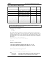
asix4
User’s Manual
see and get more…
CtLG - Driver of Dedicated Protocol for LG
Master-K and Glofa GM PLCs
User’s Manual
Doc. No. ENP4028
Version: 29-08-2005
asix4
User’s Manual
ASKOM® and asix ® are registered trademarks of ASKOM Spółka z o.o., Gliwice. Other brand
names, trademarks, and registered trademarks are the property of their respective holders.
All rights reserved including the right of reproduction in whole or in part in any form. No part of
this publication may be reproduced or transmitted in any form or by any means, electronic or
mechanical, including photocopying, recording, or by any information storage and retrieval
system, without prior written permission from the ASKOM.
ASKOM sp. z o. o. shall not be liable for any damages arising out of the use of information
included in the publication content.
Copyright © 2005, ASKOM Sp. z o. o., Gliwice
ASKOM Sp. z o. o., ul. Józefa Sowińskiego 13, 44-121 Gliwice,
tel. +48 (0) 32 3018100, fax +48 (0) 32 3018101,
http://www.askom.com.pl, e-mail: [email protected]
asix4
CtLG - Driver of Dedicated Protocol for LG…
1. CtLG - Driver of Dedicated Protocol for LG
Master-K and Glofa GM PLCs
1.1.
Driver Use
The CtLG driver is designed to exchange data between the asix system and LG Industrial
Systems Master – K and Glofa GM PLCs with use of an RS232 port. The driver enables
access to LG PLC data addressed directly by passing the address of the variable within the
device. The driver allows simultaneous handling of many LG PLCs.
1.2.
Declaration of Transmission Channel
The syntax of declaration of transmission channel using the driver is as follows:
Channel=UNIDRIVER, CtLG, Port=port_number; Speed=transmission_speed;
StopBits=number_of_stop_bits;ParityBit=control_of_frame_parity;
DataBits=number_of_data_bits; NrOfBlocks=number_of_blocks;
TimeSynchr=address[:period];
where:
UNIDRIVER
CtLG
Port
Speed
StopBits
ParityBit
DataBits
NrOfBlocks
TimeSynchr
©ASKOM, Gliwice
- name of universal UNIDRIVER;
- name of driver used for communication with LG PLC;
- number of the COM serial port;
- speed of transmission between computer and device; the
following speeds are acceptable: 1200, 2400, 4800, 9600, 19200,
38400, 56000, 57600, 115200, 128000; every speed is given in bits
per second, i.e. bauds; a default value is 1200 Bd;
- number of stop bits: 1 or 2; for the GlofaGM6 PLC this
parameter is built into the controller on a permanent basis and
amounts to 1; a default value of the parameter is 1;
- defines the method of frame parity control; available options: no,
parity_control, odd_parity_contol; as substitutes for these options
you may use, respectively: 0, 1, 2; for GlofaGM6 PLC this
parameter is built into the controller on a permanent basis and
amounts to 0, i.e. no; a default value of the parameter is
parity_control;
- number of data bits per frame: 7 or 8; for the GlofaGM6 PLC this
parameter is built into the controller on a permanent basis and
amounts to 8; a default value of the parameter is 8;
- max number of blocks specifying variables in a single read
operation; a maximum value of the parameter is 16; the parameter
has been introduced because GLOFA PLC properly executes
queries for max 4 blocks (inconsistently with specification); a
default value of the parameter is 16;
- for Glofa PLCs it is a direct address of the table of 9 bytes, in the
controller that PC's system time is to be entered into. The table will
be filled in with BCD-code numbers as follows:
time[0] = two younger digits of year
time[1] = month
time[2] = day of month
August 2005
3
asix4
CtLG - Driver of Dedicated Protocol for LG…
time[3] = hour
time[4] = minutes
time[5] = seconds
time[6] = day of week (Monday - 0, Tuesday – 1,... Sunday - 6)
time[7] = two older digits of year
time[8] = 1
e.g. 2001 – 03 – 15 18:30:45 Tuesday: time[0] = 01, time[1] = 03, time[2] = 15, time[3] =
18, time[4] = 30, time[5] = 45, time[6] = 03, time[7] = 20,
On Glofa controller's side, you should execute the command RTC_SET argument. The
argument is a symbolic address of the table of 8 bytes. When declaring this variable, in the
Memory allocation field select the Assign(AT) option and pass the direct address of the
variable in the transmission channel declaration. Upon the system time is rewritten from
the PC to the controller, the value 1 is assigned to the ninth element of the table.
In case of the MASTER-K PLC, TimeSynchr is the address of the table of word type
consisting of five elements, which is available in the controller N. The table is filled in
with BCD-code numbers as follows:
time[0] = older byte = 2 younger digits of year, younger byte = month (1..12)
time[1] = older byte = day of month (1..31), younger byte = hour
time[2] = older byte = minutes, younger byte = seconds
time[3] = older byte = 2 older digits of year, younger byte = day of week (Sunday – 0,
Monday – 1...Saturday – 6)
time[4] = 1
With the exception of time[4], these words should be rewritten into a special area of the
memory and the appropriate bit should be set.
period
- default parameter to define the interval in seconds at which time
will be rewritten from the PC to the controller. By default, the
synchronization time is 60 seconds.
EXAMPLE
An example of declaration of channel in which time will be synchronised for the controller
numbered 6 (GLOFA type) by the write into the area starting with MB10 (every 25
seconds):
PLC1 = UNIDRIVER, CtLG, Port=2;Speed=9600; StopBits=1;
ParityBit=odd_parity_control; DataBits=8; TimeSynchr=6.MB10:25
1.3.
Addressing the Process Variables
Addressing the Variables in Master – K family
The following direct address is only acceptable:
ControllerNo.TypeOfDevice.Address
where:
Controller no
- number between 0 and 31.
Type of device (see: Table 1).
4
August 2005
©ASKOM, Gliwice
asix4
CtLG - Driver of Dedicated Protocol for LG…
Table 1. Types of Devices in Master-K Family.
Type of Device
P (Input/Output relay)
M ( auxiliary relay )
K ( keep relay )
L ( link relay )
F ( special relay )
T ( timer contact relay )
T ( timer elapsed value )
C ( counter contact relay )
C ( counter elapsed value )
S ( step controller )
D ( data register )
Range of Device
P0 ~ P0031 ( 32 words )
P0.0 ~ P31.15 ( 32 × 16 bits )
M0 ~ M191 ( 192 words )
M0.0 ~ M191.15 ( 192 × 16 bits)
K0 ~ K31 ( 32 words )
K0.0 ~ K31.15 ( 32 × 16 bits )
L0 ~ L63 ( 64 words )
L0.0 ~ L63.15 ( 64 × 16 bits )
F0 ~ F63 ( 64 words )
F0.0 ~ F63.15 ( 64 × 16 bits )
T0.0 ~ T0.255 ( 256 bits )
T0 ~ T255 ( 256 words )
C0.0 ~ C0.255 (256 bits )
C0 ~ C255 ( 256 words )
S0 ~ S99 ( 100 sets )
D0 ~ D4999 ( 5000 words )
Read/Write
Read/Write
Bit/Word
Both
Read/Write
Both
Read/Write
Both
Read/Write
Both
Read
Both
Read/Write
Read/Write
Read/Write
Read/Write
Read/Write
Read/Write
Both
Both
Both
Both
Word only
Word only
NOTE
T and C devices should not be used for bit addressing because it does not work due to
error in the controller's operating system.
There are two types of variables:
• bit,
• word.
The variable address may contain up to 8 characters (without device type character and ‘.’
character, if any). The address is given in decimal format. When bit is addressed within a
word, the bit number (from 0 to 15) is given after a dot. An exception to this rule is Timer
and Counter types. As you can see in the above table, bits for these types are addressed
from 0 to 255.
For example, 0. M5 – word with the address 5
0. M5.10 – eleventh bit in the word with the address 5
EXAMPLE
Examples of variable declarations:
JJ_00, variable of WORD type with address M1, 0.M1, PLC1, 1, 1, NIC
JJ_01, variable of BIT type with address M5.10, 0.M5.10, PLC1, 1, 1, NIC
Addressing the Variables in Glofa – GM Family
The direct address has the following format:
ControllerNo.TypeOfDevice.TypeOfVariable.Address
where:
ControllerNo
TypeOfDevice
©ASKOM, Gliwice
- defines the controller number and is a number between 0 and 31;
- defines the device type; the following types are available:
August 2005
5
asix4
CtLG - Driver of Dedicated Protocol for LG…
• M (internal memory),
• Q (output),
• I (Input).
The range of addressing for these devices is configurable and depends on the type of
device.
All of these devices can be both written to and read from.
TypeOfVariable - defines the variable type. The following types are available:
• X – bit,
• B – byte
• W – word,
• D – double word.
For the M device the address is given in decimal format and may contain maximum 13
characters, without the character of the device and variable type, e.g.:
3.MW1 - word with the address 1 from the dictionary no 3
If you want to address a bit in the M device within a byte, word or double word, the bit
number (counted from 0) in decimal format should be given after a dot, for example:
4.MW1.14 - fourteenth bit in the word 1 from the dictionary 4
5.MD2.30 - thirteenth bit in the double word 2 from the dictionary 5
Bit can also be addressed directly using the X character, e.g.:
0.MX10 - tenth bit.
In case of addressing Q and I devices, the address is given in decimal format. These are
three numbers (base, slot, number) separated with the ‘.’ character, e.g.:
2.QX3.1.4 - controller no 2, 3 base, 1 slot, 4th bit,
3.IW2.4.1 - controller no 3, 2 base, 4 slot, 1st word.
EXAMPLE
Examples of variable declarations:
JJ_00, VARIABLE OF WORD TYPE WITH ADDRESS MW1, 0.MW1, PLC1, 1, 1, NIC
JJ_01, variable of BIT type with address QX3.1.4, 0.QX3.1.4, PLC1, 1, 1, NIC
1.4.
Time Marker
Values of variables read from LG are assigned a PC's time stamp.
1.5.
Driver Parameterization
The driver parameterization takes place with use of the separate section named [CTLG] which
is placed in the initialisation file of an asix application. Using this section, you may declare:
• log file,
• log file size,
• telegram log.
6
August 2005
©ASKOM, Gliwice
asix4
CtLG - Driver of Dedicated Protocol for LG…
LOG_FILE = log_file_name
Meaning
Default value
Defining
- for diagnostic purposes the text-type log file into which messages
about driver operation status are written is used.
- by default, the log file is not created.
- manual.
LOG_FILE_SIZE=number
Meaning
Default value
Defining
- this item is used to define the size of the log file defined with use
of the LOG_FILE item.
- by default, the log file size is 1 MB.
- manual.
LOG_OF_TELEGRAMS =yes | No
Meaning
Default value
Defining
- this item allows contents of telegrams transferred between the
driver and controllers to be written into the log file (declared with
use of the LOG_FILE item). The referred item should only be
used in the asix system start-up stage.
- by default, value of this item is set to NO.
- manual.
EXAMPLE
An example of the driver section:
[CTLG]
LOG_FILE=d:\tmp\ctLG\LG.log
LOG_FILE_SIZE=3
©ASKOM, Gliwice
August 2005
7
asix4
CtLG - Driver of Dedicated Protocol for LG…
8
August 2005
©ASKOM, Gliwice
asix4
List of Tables
2. List of Tables
Table 1. Types of Devices in Master-K Family.................................................................................................... 5
©ASKOM, Gliwice
August 2005
9
asix4
List of Tables
10
August 2005
©ASKOM, Gliwice
asix4
Table of Contents
1.
CTLG - DRIVER OF DEDICATED PROTOCOL FOR LG MASTER-K AND GLOFA GM
PLCS
1.1.
1.2.
1.3.
1.4.
1.5.
2.
3
DRIVER USE
DECLARATION OF TRANSMISSION CHANNEL
ADDRESSING THE PROCESS VARIABLES
TIME MARKER
DRIVER PARAMETERIZATION
3
3
4
6
6
LIST OF TABLES
©ASKOM, Gliwice
9
August 2005
11