1
To our customers,
Old Company Name in Catalogs and Other Documents
On April 1st, 2010, NEC Electronics Corporation merged with Renesas Technology
Corporation, and Renesas Electronics Corporation took over all the business of both
companies. Therefore, although the old company name remains in this document, it is a valid
Renesas Electronics document. We appreciate your understanding.
Renesas Electronics website: http://www.renesas.com
April 1st, 2010
Renesas Electronics Corporation
Issued by: Renesas Electronics Corporation (http://www.renesas.com)
Send any inquiries to http://www.renesas.com/inquiry.
Notice
1.
2.
3.
4.
5.
6.
7.
All information included in this document is current as of the date this document is issued. Such information, however, is
subject to change without any prior notice. Before purchasing or using any Renesas Electronics products listed herein, please
confirm the latest product information with a Renesas Electronics sales office. Also, please pay regular and careful attention to
additional and different information to be disclosed by Renesas Electronics such as that disclosed through our website.
Renesas Electronics does not assume any liability for infringement of patents, copyrights, or other intellectual property rights
of third parties by or arising from the use of Renesas Electronics products or technical information described in this document.
No license, express, implied or otherwise, is granted hereby under any patents, copyrights or other intellectual property rights
of Renesas Electronics or others.
You should not alter, modify, copy, or otherwise misappropriate any Renesas Electronics product, whether in whole or in part.
Descriptions of circuits, software and other related information in this document are provided only to illustrate the operation of
semiconductor products and application examples. You are fully responsible for the incorporation of these circuits, software,
and information in the design of your equipment. Renesas Electronics assumes no responsibility for any losses incurred by
you or third parties arising from the use of these circuits, software, or information.
When exporting the products or technology described in this document, you should comply with the applicable export control
laws and regulations and follow the procedures required by such laws and regulations. You should not use Renesas
Electronics products or the technology described in this document for any purpose relating to military applications or use by
the military, including but not limited to the development of weapons of mass destruction. Renesas Electronics products and
technology may not be used for or incorporated into any products or systems whose manufacture, use, or sale is prohibited
under any applicable domestic or foreign laws or regulations.
Renesas Electronics has used reasonable care in preparing the information included in this document, but Renesas Electronics
does not warrant that such information is error free. Renesas Electronics assumes no liability whatsoever for any damages
incurred by you resulting from errors in or omissions from the information included herein.
Renesas Electronics products are classified according to the following three quality grades: “Standard”, “High Quality”, and
“Specific”. The recommended applications for each Renesas Electronics product depends on the product’s quality grade, as
indicated below. You must check the quality grade of each Renesas Electronics product before using it in a particular
application. You may not use any Renesas Electronics product for any application categorized as “Specific” without the prior
written consent of Renesas Electronics. Further, you may not use any Renesas Electronics product for any application for
which it is not intended without the prior written consent of Renesas Electronics. Renesas Electronics shall not be in any way
liable for any damages or losses incurred by you or third parties arising from the use of any Renesas Electronics product for an
application categorized as “Specific” or for which the product is not intended where you have failed to obtain the prior written
consent of Renesas Electronics. The quality grade of each Renesas Electronics product is “Standard” unless otherwise
expressly specified in a Renesas Electronics data sheets or data books, etc.
“Standard”:
8.
9.
10.
11.
12.
Computers; office equipment; communications equipment; test and measurement equipment; audio and visual
equipment; home electronic appliances; machine tools; personal electronic equipment; and industrial robots.
“High Quality”: Transportation equipment (automobiles, trains, ships, etc.); traffic control systems; anti-disaster systems; anticrime systems; safety equipment; and medical equipment not specifically designed for life support.
“Specific”:
Aircraft; aerospace equipment; submersible repeaters; nuclear reactor control systems; medical equipment or
systems for life support (e.g. artificial life support devices or systems), surgical implantations, or healthcare
intervention (e.g. excision, etc.), and any other applications or purposes that pose a direct threat to human life.
You should use the Renesas Electronics products described in this document within the range specified by Renesas Electronics,
especially with respect to the maximum rating, operating supply voltage range, movement power voltage range, heat radiation
characteristics, installation and other product characteristics. Renesas Electronics shall have no liability for malfunctions or
damages arising out of the use of Renesas Electronics products beyond such specified ranges.
Although Renesas Electronics endeavors to improve the quality and reliability of its products, semiconductor products have
specific characteristics such as the occurrence of failure at a certain rate and malfunctions under certain use conditions. Further,
Renesas Electronics products are not subject to radiation resistance design. Please be sure to implement safety measures to
guard them against the possibility of physical injury, and injury or damage caused by fire in the event of the failure of a
Renesas Electronics product, such as safety design for hardware and software including but not limited to redundancy, fire
control and malfunction prevention, appropriate treatment for aging degradation or any other appropriate measures. Because
the evaluation of microcomputer software alone is very difficult, please evaluate the safety of the final products or system
manufactured by you.
Please contact a Renesas Electronics sales office for details as to environmental matters such as the environmental
compatibility of each Renesas Electronics product. Please use Renesas Electronics products in compliance with all applicable
laws and regulations that regulate the inclusion or use of controlled substances, including without limitation, the EU RoHS
Directive. Renesas Electronics assumes no liability for damages or losses occurring as a result of your noncompliance with
applicable laws and regulations.
This document may not be reproduced or duplicated, in any form, in whole or in part, without prior written consent of Renesas
Electronics.
Please contact a Renesas Electronics sales office if you have any questions regarding the information contained in this
document or Renesas Electronics products, or if you have any other inquiries.
(Note 1) “Renesas Electronics” as used in this document means Renesas Electronics Corporation and also includes its majorityowned subsidiaries.
(Note 2) “Renesas Electronics product(s)” means any product developed or manufactured by or for Renesas Electronics.
APPLICATION NOTE
SH2/SH2A Family
Using a Fixed Point Math Library
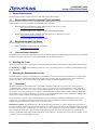
Introduction
The purpose of this application note is to give examples of using the Fixed Point Math library for the SH2 and SH2A
families.
In many applications it is necessary to maintain accuracy when doing math and floating point type calculations are
desirable. However, many smaller microcontrollers do not have an FPU available. When this happens, engineers
typically resort to fixed point math, which can help maintain the best “dynamic range” while using the Integer math
instructions and multiplier hardware of a non-FPU microcontroller unit.
This application note does not review Fixed Point concepts or number ranges; those are left to the Fixed Point Library
Users manual (see references section). Rather, this attempts to give examples of real-life uses of fixed point libraries.
NOTE: This application note is not intended for the SH2A families with integrated FPU in the core, although it may be
helpful in these devices when receiving fixed point data from other Microcontrollers and/or applications.
Target Device
SH2/SH2A
Contents
1.
Demo Requirements ......................................................................................................................... 2
2.
Building the Code .............................................................................................................................. 2
3.
Running the Demonstration Code..................................................................................................... 2
4.
Selecting Resolutions for Variables .................................................................................................. 6
5.
Multiple Build Configurations............................................................................................................. 9
6.
Appendix A: Library Usage in HEW ................................................................................................ 10
7.
Glossary .......................................................................................................................................... 13
REU05B0116-0100/Rev.1.00
November 2009
Page 1 of 15
SH2/SH2A Family
Using a Fixed Point Library
1.
Demo Requirements
The following items are required in order to build and run this demonstration.
1.1
Required Renesas Development Tools (software)
The following tools and their versions are required for building the demonstration and following the tutorial. Evaluation
editions of these tools are all available for download from our website.
•
High-performance Embedded Workshop (HEW) Version 4.06.xx.xx (or later)
http://www.renesas.com/download
Web Search Keyword: “High-performance Embedded Workshop”
•
Renesas SuperH RISC Engine Standard Toolchain Version 9.3. Release 00 (or later)
http://www.renesas.com/download
Web Search Keyword: “SuperH Compiler”
1.2
Required Hardware for Demo
The following items are needed for the demo below.
•
1.3
RSK for SH7286 (includes E10A for Starter Kits).
http://www.renesas.com/rsk
Demonstration Software
The Demonstration software is intended for use with the Renesas RSK board. More detailed documentation on the RSK
hardware is included with the kit or can be downloaded from the Renesas Web site.
2.
Building the Code
The demonstration software can be built by opening the HEW Workspace (FP_Demo.hws) and building the code using
the “Build All” icon
E10A and HEW.
3.
. The resulting ‘FP_Demo.abs’ file in the ‘Debug’ directory can then be downloaded using the
Running the Demonstration Code
The demonstration is setup to use data from the potentiometer connected to ADC Unit 0, channel 0. It is assumed the
user has already setup the SH7286 RSK using the QSG and is familiar with the operation of the E10A and the SH
Family tool chains. The user should refer to the RSK schematic for additional detail as necessary.
3.1
Overview
The demonstration uses the Potentiometer on the RSK to simulate readings from current sensors and to generate
“commanded motor voltages” in a motor control scenario. Since it has only one Potentiometer it cannot run both
scenarios at the same time. It uses a static variable named ad_demo to select which scenario to run. When ad_demo is
set to logic 0, it uses the potentiometer to simulate commanded motor voltages which are then turned into PWM Sine
waves of the correct voltage. If ad_demo is set to logic 1, the potentiometer will be used to simulate the reading from a
current sensor and the resulting values displayed in the watch window.
We provided two scenarios to give examples that the resolution and size of variables are determined by the system
requirements. The engineer can choose these based on the range of numbers he needs to represent as well as the
dynamic range he needs for his control system to operate properly.
IMPORTANT NOTE: The demonstration code calls the floating point library in order to display the actual values in
the watch windows. When using the Fixed Point library, it is never required to convert the fixed point values to floating
point for your calculations, control loops, etc. There may be some reasons for converting Fixed Point to Floating Point
such as displaying fixed point values in easily readable floating point form on the User Interface or sending data to
another program/MCU that might need Floating Point results. However, the fixed point versions of the variables are all
you need to use in the math application itself.
REU05B0116-0100/Rev.1.00
November 2009
Page 2 of 15
SH2/SH2A Family
Using a Fixed Point Library
3.2
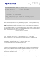
Adding Correct Watch Variable
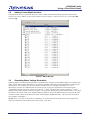
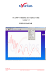
The project built session is saved with the correct watch variable for the demonstration assigned. In the event the
session is not correct, add the correct watch variables as shown in Figure 1. Be sure they are set to Auto-update (R
rather than )
Figure 1: Watch Window
3.3
Simulating Motor Voltage Generation
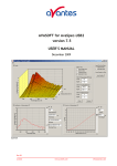
When ad_demo=0, the demonstration generates a simulated motor voltage out of the PWM channels in complementary
mode. For the Motor voltage demonstration we picked a value that could easily be both simulated and verified in the
demonstration. For this demo it is set-up to generate simulate Sine wave voltages to the Motor of 0 – 5V so
functionality can easily be confirmed with an oscilloscope. By varying the potentiometer (which represents the
“commanded voltage”), the motor voltage will go from 0 – 5 Volts. The fixed point value in resolution 210 will be
displayed in the watch window in motor_volts_M10. The equivalent floating point will be displayed motor_volts_float.
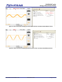
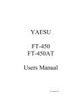
The Motor Volts can be viewed as an output by adding a simple RC filter to the PWM output pin. Select the RC time
constant such that it filters the 20 kHz carrier while not filtering the fundamental 50Hz. The scope shots will look as
seen in Figure 2 and Figure 3.
NOTE: motor_volts_float is only used for “readability”. It would not be used in normal motor control applications,
rather you would work with the fixed point version motor_volts_M10.
REU05B0116-0100/Rev.1.00
November 2009
Page 3 of 15
SH2/SH2A Family
Using a Fixed Point Library
Figure 2: Sine wave (half voltage) generated post RC filter and Associated Watch Values.
a
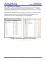
Figure 3: Sine wave (full voltage) generated post RC filter and Associated Watch Values.
REU05B0116-0100/Rev.1.00
November 2009
Page 4 of 15
SH2/SH2A Family
Using a Fixed Point Library
3.4
Simulating Current Readings
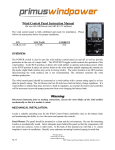
When ad_demo=1, the demonstration uses the potentiometer to simulate the input from a current sensor. Since the
variables are set for auto-update, simply double click the ad_demo entry and change the value to 1 in the dialog box.
Once ad_demo equals 1, the potentiometer readings will be reflected in the current_measured_M10. The potentiometer
is scaled to simulate a sensor that reads from 0 to 10 amperes full scale in resolution 210. The floating point value will
be displayed in current_measured_float.
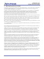
In the demonstration, we set the Over current value to 5 Amperes. Note that when you cross 5 Amperes, the string in
the buffer goes from “Current OK” to “Over-Current”
NOTE: current_measured_float is only used for “readability”. It would not be used in normal motor control
applications, rather you would work with the fixed point version current_measured_M10.
Figure 4: Watch Windows showing Normal and Over Current Detection.
REU05B0116-0100/Rev.1.00
November 2009
Page 5 of 15
SH2/SH2A Family
Using a Fixed Point Library
4.
Selecting Resolutions for Variables
It is important to select the proper resolutions when using a fixed point library. You can simply select a resolution and
live with the resulting rounding error or you can select the maximum resolution, minimize the rounding error and
provide the dynamic range required by your application.
In addition, you must be aware that large number may cause overflow errors in your calculations. It is recommended
that you check the ranges of the math used on your fixed point numbers, including making sure some of the
intermediate values do not cause overflow. Picking resolutions that do not have you “carrying around” excess
fractional bits (i.e.bits not needed to meet the accuracy requirements of your system) will reduce the chances of
overflowing your results when you add or do scaled multiply operations.
Before we jump into the hardware examples, it might be good to discuss some Fixed Point Basics, starting with notation.
Qf - This notation just designates the number of fractional bits (f) and not the size of the number. For example Q5 only
says that there are 5 fractional bits, and does not say number of bits. Typically, Signed 16 or 32 bit variables are used.
Qm.f – This form define both the magnitude (m) and the Fractional part (f). A number like Q3.28 says that you have 3
integer bits and 28 fractional bits. With 1 sign bit, this fits in a signed 32 bit variable.
fxm.b – Similar to Qm.f, it use the second bit number (b) to describe the number of bits, this a number like fx1.6 is fixed
point number with 1 magnitude bit and 15 fractional bits.
s:m:f – This describe the whole number, sign (s), magnitude (m) and fractional part (f). So a number like 0:8:0 describe
an unsigned 8 bit integer.
Next we will look at some of the basic rules. In fixed point arithmetic we are basically doing exponential arithmetic, so
we have to abide the rule for exponential arithmetic.
Adding & Subtracting: to add or subtract fixed point numbers, they must be the same resolution. For example to add a
Q5 and a Q7 you must convert one of them. In general, you would convert the lower resolution up to the higher
resolution, because it would simply mean shifting in 0’s on the LSB end, and thus not affecting the actual answer.
Multiplying: to multiply, you simply multiply the numbers and add the Q factor to determine the resolution of the new
number. In general this is not a problem for two reasons, a) most modern MCUs have a hardware multiplier and
secondly, most libraries will use the correct intermediate value (for 16x16 = 32 bit result) and then return a normalized
number.
Dividing: For most MCUs dividing is an issue since most divides are multi-clock. No way around it, you just need to
minimize the number of divides. That being said, if you have a constant that you need to divide by, a one simple
performance enhancement is to multiply by its inverse. This is easy to do with fixed point arithmetic.
Scaled Multiplication: This is a little unique. This is used when multiplying numbers of two different resolutions. For
example if you want to multiply a number of Q5 and Q7. The resulting would be Q to the 12 and without scaled
multiply, the library would not know what resolution to return. So for example suppose you want to multiply Voltage
and Current to get power. P=IE, but I is in Q10 and E is in Q5; perfect if you need P in Q15 (probably in a 32 bit signed
return value). But suppose you need P as a 16 bit signed result in Q8. You would called a scaled multiply with a scaling
value of 5 (i.e. result will be Q12 you need to scale back by Q5 to get result in Q8).
Overflow: Overflow is something that you must contend with, but it is easy to avoid. Multiplying numbers of the same
resolution is usually not a problem since they are normalized on return. Adding is a minor issue because in most
control systems you multiply and divide. Overflow on One level of addition can be avoided by providing an additional
bit. When we are selecting resolution we will always allow 1 bit which we will call “safety margin”. This means you
can add two numbers of the same resolution without worrying about overflow. If you need to add more than two
numbers you will have to scale if your numbers will cause an overflow.
Finally, as a general rule, we will pick the size of variable, then pick the resolution we will need to fit this range into the
magnitude of the number. Sometimes this means we will carry extra resolution bits, but this is usually not an issue
since the library will multiply and normalize on its return, so it costs us little.
REU05B0116-0100/Rev.1.00
November 2009
Page 6 of 15
SH2/SH2A Family
Using a Fixed Point Library
For the following example we will assume a 12 bit ADC with an input voltage range (Vref) range of 5VDC. You can
adjust the equations accordingly for 3.3V operation. Also Code in these examples if written for clarity.
Example 1: Voltage Sensor
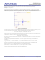
Assume you need to monitor an incoming DC bus voltage in a lighting control design. To do this you use a simple
voltage divider on the DC bus and apply it to the input of the ADC. Since this is a line powered application you need to
divide it down by about 100:1. You’re resulting schematic is shown in Figure 5 with V_BUS attached to the ADC.
Figure 5: Voltage Monitor
You chose to do all you work with 16 Bit Fixed Point math, but you want to choose a resolution to minimize your error.
You must evaluate the range of the number. Therefore maximum HIGH_VOLTAGE measurable is:
(Vref * (R40 + R42))/R43 = (5*950K)/10K = 480 volts
In order to fit this into a 16 bit fixed point representation and cover the range, let’s assume 1 bit for sign and one bit for
“safety margin”. Therefore we will use 14 bit and a resulting resolution of:
Log2(214/480) = 5.09 or resolution 5
This means to represent the maximum value of 480 volts, we should use FIX5 resolution. So 480 volts would result in
a value of 15360.
Your ADC bit weight would then be 480/4096 or ~0.1171875. Using the same reasoning, we should then use a
resolution of:
Log2(214/0.117875) = ~17.084 so round down ~ 17, so numbers read from ADC are in 217 so 1 bit is 15360
So suppose we read 2048 from the ADC, intuitively we know that is 240VDC, but let’s go through the math.
(2048*0.117875 in 217)/ 212) = HIGH_VOLTAGE in 25 so your HIGH_VOLTAGE is:
(2048*15360)/212 = 7680, but remember, this is 25, so your voltage is 7680/25 = 240VDC
Code wise with the Fixed Point library this would look something like this:
REU05B0116-0100/Rev.1.00
November 2009
Page 7 of 15
SH2/SH2A Family
Using a Fixed Point Library
#define VBUS_ADC_BIT
15360L
#define BUS_OVERVOLTAGE 12800L
// 0.117875 in 2^17
// 400 volts in 2^5
FIX5
// 0 until read by ADC
high_voltage = 0;
void read_bus_voltage(void)
{
FIX17 raw_reading;
raw_reading = get_AD_data(V_BUS);
// Fixed Point Multiply scaled back by 2^12, results in 2^5 value
high_voltage = FIX_mul_SCALE12(raw_reading, VBUS_ADC_BIT);
}
Example 2: Current Sensor
Assume you need to monitor current in a motor winding in a motor control design. So you chose a high-side DCCT
(DC Current Transducer). From the data sheet you see that it outputs a signal at 100mV/A. So your full current range
is ±2.5/(100mV/A) or ±25A or a range of 50A.
NOTE: Remember, for these examples a reading of 2048 (1/2 full-scale) is actually 0A since this is a bi-directional
current sensor (i.e. current flows and is measured in both directions)
You chose to do all you work with 16 Bit Fixed Point math, but you want to choose a resolution to minimize your error.
So you must evaluate the range of the number. The DCCT determines the maximum current we can measure. In order
to fit this into a 16 bit fixed point representation and cover the range, let’s assume 1 bit for sine and one bit for “safety
margin”. Therefore we will use 14 bit and a resulting resolution of:
Log2(214/50) = 8.35 so you use resolution 8
This means to represent the maximum value of ±25 volts, we should use FIX8 resolution. So 25A would result in a
value of 6400.
Your ADC bit weight would then be 25/4096 (12 bit ADC) or ~0.012207031. Using the same reasoning, we should
then use a resolution of:
Log2(214/0.012207031) = TBD so chose 20, so numbers read from ADC are in 220 so 1 bit is 12800
Assume we read 3072 from the ADC; now intuitively we know that this is 12.5A, but let’s go through the math.
Subtract 0 current offset, 3072-2048 = 1024
(1024*0.012207031 in 220)/ 212) = AMPS in 28 so your current is:
(1024*12800)/212 = 3200, but remember, this is 28, so your current is 3200/28 = 12.5A
Code wise with the Fixed Point library this would look something like this:
NOTE: the zero current offset is hard coded in this example. Actual Zero Current Offset could be determined in
software at run time.
Comment on Coding Style: In this demo we chose to add a suffix on the variables that are in fixed point format. We
chose to do this so we did not have to keep referring back to the declaration to determine its resolution. If we see a
variable xyz_M10, we know it is in resolution 10. So one example of how this helps keep things straight is in the scaled
multiply. If you multiply abc_M5 and def_M7 and you are putting it into a variable xyz_M10, you know you need to
scale back by 2. Some may chose to use prefix such as FIX10_abc, either way it is a good idea to do whatever
necessary to keep your resolutions correct.
REU05B0116-0100/Rev.1.00
November 2009
Page 8 of 15
SH2/SH2A Family
Using a Fixed Point Library
#define I_ADC_BIT
#define OVER_CURRENT
#define ZERO_I_OFFSET
FIX8
12800L
5120L
2048L
motor_current = 0;
// 0.012207031 in 2^20
// 20 volts in 2^8
// Midpoint on 12 bit ADC
// 0 until read by ADC
void read_current(void)
{
FIX8 raw_reading;
raw_reading = get_AD_data(V_BUS);
raw_reading -= ZERO_I_OFFSET;
// 2^20 reading
// Multiply 2^20 bit weight scaled back by 2^12, results in 2^8 value
motor_current = FIX_mul_SCALE12(raw_reading, I_ADC_BIT);
}
5.
Multiple Build Configurations
The demo contains two Build setting. The normal build, simply called “Debug” will run the demo code as described
above. The additional session is called Debug_with_vectors.
Debug_with_vectors will include a series of test vectors to be included in the build. These will run through a series of
functions calls that attempt to exercise a large number of functions calls. This may be beneficial to software engineers
using Fixed Point for the first time, to see the input numbers and the results of the fixed point function call.
NOTE: It is impossible to test all the permutations of the input values possible, so these are included as examples only.
Any issues with the fixed point library should be reported to Renesas Tech Support.
REU05B0116-0100/Rev.1.00
November 2009
Page 9 of 15
SH2/SH2A Family
Using a Fixed Point Library
6.
Appendix A: Library Usage in HEW
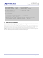
This section will show a practical example of how the Filter Library may be integrated into an overall HEW Project.
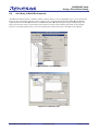
6.1
Local to Project.
The SH2A Fixed Point Library is simple to add locally to any existing HEW project. To incorporate the Library locally
into an existing project, drag and drop the SH2A Fixed Point Library folder into the project directory where you are
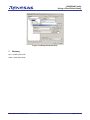
working. Then simply navigate through the menu Project î Add Files to Project î Library (See Figure 6 through
Figure 8). This will make it local to this project. For more information on Library files refer to the HEW User’s Manual.
Figure 6: Add File
Figure 7: Select LIB type
REU05B0116-0100/Rev.1.00
November 2009
Page 10 of 15
SH2/SH2A Family
Using a Fixed Point Library
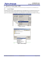
Figure 8: Select Fixed Point Library file
NOTE: Be sure to select the correct library based on device type being used, SH2 or SH2A.
REU05B0116-0100/Rev.1.00
November 2009
Page 11 of 15
SH2/SH2A Family
Using a Fixed Point Library
6.2
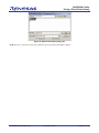
As Library in Build Environment
The SH2A Fixed Point Library is simple to add as a common library to any existing HEW project. To incorporate the
Library from a central library directory into an existing project, navigate through the menu Build î SuperH RISC
Engine Standard Toolchain î Link/Library Tab î Library Files î Add (See figures Figure 9 through Figure 11).
This project will now always use the .lib file at this directory location when a build is performed. In this example
Library is in a folder named UserLib. For more information on Library files refer to the HEW User’s Manual.
Figure 9: Build Toolchain Menu
Figure 10: Link/Library Tab
REU05B0116-0100/Rev.1.00
November 2009
Page 12 of 15
SH2/SH2A Family
Using a Fixed Point Library
Figure 11:Adding Library Directory
7.
Glossary
FPU – Floating Point Unit
QSG – Quick Start Guide
REU05B0116-0100/Rev.1.00
November 2009
Page 13 of 15
SH2/SH2A Family
Using a Fixed Point Library
References
Fixed Point Library Users Manual, REJ05J0001-0101
Wikipedia - http://en.wikipedia.org/wiki/Fixed-point_arithmetic
ISO/IEC TR 18037:2008 – Programming Languages - C - Extensions to support Embedded Processors
Website and Support
Renesas Technology Website
http://www.renesas.com/
Inquiries
http://www.renesas.com/inquiry
[email protected]
Revision Record
Rev.
1.00
Date
Sept.01.09
REU05B0116-0100/Rev.1.00
Description
Page
Summary
—
First edition issued
November 2009
Page 14 of 15
SH2/SH2A Family
Using a Fixed Point Library
Notes regarding these materials
1.
2.
3.
4.
5.
6.
7.
8.
9.
10.
11.
12.
13.
This document is provided for reference purposes only so that Renesas customers may select the appropriate
Renesas products for their use. Renesas neither makes warranties or representations with respect to the
accuracy or completeness of the information contained in this document nor grants any license to any intellectual
property rights or any other rights of Renesas or any third party with respect to the information in this document.
Renesas shall have no liability for damages or infringement of any intellectual property or other rights arising out
of the use of any information in this document, including, but not limited to, product data, diagrams, charts,
programs, algorithms, and application circuit examples.
You should not use the products or the technology described in this document for the purpose of military
applications such as the development of weapons of mass destruction or for the purpose of any other military
use. When exporting the products or technology described herein, you should follow the applicable export
control laws and regulations, and procedures required by such laws and regulations.
All information included in this document such as product data, diagrams, charts, programs, algorithms, and
application circuit examples, is current as of the date this document is issued. Such information, however, is
subject to change without any prior notice. Before purchasing or using any Renesas products listed in this
document, please confirm the latest product information with a Renesas sales office. Also, please pay regular
and careful attention to additional and different information to be disclosed by Renesas such as that disclosed
through our website. (http://www.renesas.com)
Renesas has used reasonable care in compiling the information included in this document, but Renesas
assumes no liability whatsoever for any damages incurred as a result of errors or omissions in the information
included in this document.
When using or otherwise relying on the information in this document, you should evaluate the information in light
of the total system before deciding about the applicability of such information to the intended application.
Renesas makes no representations, warranties or guaranties regarding the suitability of its products for any
particular application and specifically disclaims any liability arising out of the application and use of the
information in this document or Renesas products.
With the exception of products specified by Renesas as suitable for automobile applications, Renesas products
are not designed, manufactured or tested for applications or otherwise in systems the failure or malfunction of
which may cause a direct threat to human life or create a risk of human injury or which require especially high
quality and reliability such as safety systems, or equipment or systems for transportation and traffic, healthcare,
combustion control, aerospace and aeronautics, nuclear power, or undersea communication transmission. If you
are considering the use of our products for such purposes, please contact a Renesas sales office beforehand.
Renesas shall have no liability for damages arising out of the uses set forth above.
Notwithstanding the preceding paragraph, you should not use Renesas products for the purposes listed below:
(1) artificial life support devices or systems
(2) surgical implantations
(3) healthcare intervention (e.g., excision, administration of medication, etc.)
(4) any other purposes that pose a direct threat to human life
Renesas shall have no liability for damages arising out of the uses set forth in the above and purchasers who
elect to use Renesas products in any of the foregoing applications shall indemnify and hold harmless Renesas
Technology Corp., its affiliated companies and their officers, directors, and employees against any and all
damages arising out of such applications.
You should use the products described herein within the range specified by Renesas, especially with respect to
the maximum rating, operating supply voltage range, movement power voltage range, heat radiation
characteristics, installation and other product characteristics. Renesas shall have no liability for malfunctions or
damages arising out of the use of Renesas products beyond such specified ranges.
Although Renesas endeavors to improve the quality and reliability of its products, IC products have specific
characteristics such as the occurrence of failure at a certain rate and malfunctions under certain use conditions.
Please be sure to implement safety measures to guard against the possibility of physical injury, and injury or
damage caused by fire in the event of the failure of a Renesas product, such as safety design for hardware and
software including but not limited to redundancy, fire control and malfunction prevention, appropriate treatment
for aging degradation or any other applicable measures. Among others, since the evaluation of microcomputer
software alone is very difficult, please evaluate the safety of the final products or system manufactured by you.
In case Renesas products listed in this document are detached from the products to which the Renesas products
are attached or affixed, the risk of accident such as swallowing by infants and small children is very high. You
should implement safety measures so that Renesas products may not be easily detached from your products.
Renesas shall have no liability for damages arising out of such detachment.
This document may not be reproduced or duplicated, in any form, in whole or in part, without prior written
approval from Renesas.
Please contact a Renesas sales office if you have any questions regarding the information contained in this
document, Renesas semiconductor products, or if you have any other inquiries.
© 2009. Renesas Technology Corp. All rights reserved.
REU05B0116-0100/Rev.1.00
November 2009
Page 15 of 15