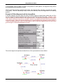
1
Nanometer Pattern Generation System User's Manual for NPGS v8 & v9 Release: 8/2004 Copyright 1988-2004 All Rights Reserved J. C. Nabity Lithography Systems P.O. Box 5354 Bozeman, MT 59717 USA (406) 587-0848 Voice (406) 586-9514 FAX E-Mail: [email protected] Internet: www.jcnabity.com Contents Introduction to NPGS __________________________________________ 1 NPGS: Overview....................................................................................................................... 1 NPGS: System Installation ........................................................................................................ 2 System Installation: Software.......................................................................................... 2 System Installation: Hardware Overview......................................................................... 4 System Installation: Summary - Check List..................................................................... 6 NPGS: Microscope Considerations ..........................................................................................12 Microscope: Overview ...................................................................................................12 Microscope: Details .......................................................................................................13 Microscope: Typical Limitations .....................................................................................14 NPGS: About this Documentation ............................................................................................15 NPGS: Legal Issues.................................................................................................................16 Quick Tutorial _______________________________________________ 17 Getting Help.............................................................................................................................17 Installing NPGS on an Office PC..............................................................................................18 Getting Started in NPGS Menu ................................................................................................18 Creating a new Project Directory..............................................................................................19 Creating a Pattern....................................................................................................................20 Creating a Run File ..................................................................................................................21 Optimizing the Microscope and Writing a Pattern.....................................................................24 Sample Patterns and Run Files................................................................................................25 Patterns for Exposure ....................................................................................................25 Patterns for Alignment ...................................................................................................28 Exposure Parameters ....................................................................................................29 Common Exposure Problems ..................................................................................................30 NPGS Menu Program _________________________________________ 32 Menu Program: Main Window ..................................................................................................32 Menu Program: Menu Commands ...........................................................................................34 Menu Program: File Menu .............................................................................................34 Menu Program: Project Menu ........................................................................................35 Menu Program: Options Menu.......................................................................................35 Menu Program: Commands Menu .................................................................................36 Menu Program: Help Menu............................................................................................39 Menu Program: Command Line Options ..................................................................................40 Pattern Design_______________________________________________ 42 Using DesignCAD LT 2000 for Windows..................................................................................42 Getting Started with DesignCAD LT...............................................................................42 Overview of Pattern Design ...........................................................................................43 Pattern Design Primitives ..............................................................................................46 Most Useful Commands ................................................................................................52 Ignored Pattern Elements ..............................................................................................53 BasicCAD Programs......................................................................................................54 Customizing DesignCAD LT ..........................................................................................58 Miscellaneous Tips for DesignCAD LT ..........................................................................58 Switching from a DOS version of DesignCAD................................................................59 Using DesignCAD 6.1 for DOS ................................................................................................61 DC6: Getting Started with DesignCAD...........................................................................61 DC6: Drawing Layers and Colors...................................................................................61 DC6: Pattern Design Entities .........................................................................................62 DC6: Most Useful Commands .......................................................................................67 Contents • Page i DC6: Ignored Commands ..............................................................................................68 DC6: Custom BasicCAD Programs................................................................................68 DC6: Customizing DesignCAD ......................................................................................71 DC6: Miscellaneous Tips ...............................................................................................72 Creating Patterns for Semi-Automatic Alignment .....................................................................74 Alignment Windows and Overlays .................................................................................74 Selecting the Size of the Alignment Window..................................................................75 Using Groups of Alignment Windows to Optimize Speed and Accuracy ........................75 Selecting the Pixel Size for Alignment Windows ............................................................76 Optional Duplicate Alignment Window Mode .................................................................76 Optional Alignment Reference Point ..............................................................................77 Defining Groups of Alignment Windows in the Run File Editor.......................................77 Creating Patterns for Fully Automatic Alignment ......................................................................77 Automatic Alignment: Overview of Pattern Design.........................................................77 Automatic Alignment: Overlay Design............................................................................78 Automatic Alignment: Registration Marks ......................................................................79 Converting from other CAD formats (GDSII, CIF, DXF,...)........................................................80 File Import: GDSII..........................................................................................................80 File Import: CIF..............................................................................................................82 File Import: Other Supported Conversions.....................................................................83 File Import: Custom Defined Conversions......................................................................83 Using the Run File Editor ______________________________________ 86 Run File Editor: Overview ........................................................................................................86 Run File Editor: Menu Commands ...........................................................................................86 Run File Editor: File Menu .............................................................................................86 Run File Editor: Edit Menu .............................................................................................87 Run File Editor: Help Menu............................................................................................88 Entity Entries and Highlighted Entity Data ................................................................................88 Run File Editor: Allow Advanced Modes Entity ..............................................................88 Run File Editor: Alignment Entity ...................................................................................90 Run File Editor: Pattern Entity........................................................................................95 Run File Editor: Array Entity...........................................................................................98 Run File Editor: Fracture Entity......................................................................................99 Run File Editor: MoveOnly Entity .................................................................................102 Run File Editor: Command Entity.................................................................................102 Run File Editor: Comment Entity..................................................................................103 Details on the Pattern Writing and Alignment Software ____________ 104 Writing and Aligning Patterns using NPGS.exe ......................................................................104 NPGS.exe: Overview...................................................................................................104 NPGS.exe: Command Line Options ............................................................................104 NPGS.exe: Miscellaneous Tips ...................................................................................105 Writing Patterns with PG.exe .................................................................................................106 PG.exe: Overview........................................................................................................106 PG.exe: Error Checking Modes ...................................................................................107 PG.exe: Time Test Mode.............................................................................................107 PG.exe: Continuous Mode...........................................................................................108 PG.exe: Optimizing the Exposure Time .......................................................................109 PG.exe: Miscellaneous Tips ........................................................................................109 Aligning Patterns with AL.exe.................................................................................................110 AL.exe: Overview ........................................................................................................110 AL.exe: Keystroke Commands ....................................................................................111 AL.exe: Miscellaneous Tips .........................................................................................115 AL.exe: Auto-Alignment Mode .....................................................................................116 Detailed Tutorial on Pattern Writing ____________________________ 120 Contents • Page ii Writing Tutorial: Sample Preparation......................................................................................120 Writing Tutorial: Microscope Optimization ..............................................................................121 Writing Tutorial: Sample Positioning.......................................................................................123 Writing Tutorial: Writing a Pattern...........................................................................................124 Writing Tutorial: Developing the Sample ................................................................................126 Writing Tutorial: View in SEM.................................................................................................126 Writing Tutorial: Lift-Off & Etching ..........................................................................................127 Detailed Tutorial on Pattern Alignment__________________________ 128 Alignment Tutorial: Step by Step Instructions.........................................................................128 Advanced Features of NPGS __________________________________ 131 Auto Logging Mode................................................................................................................131 Auto Logging: Mode/Entity Command List ...................................................................131 Auto Logging: Default Definition File............................................................................132 Auto Text Mode......................................................................................................................133 Automated Beam Current Reading ........................................................................................135 Digital Image Acquisition........................................................................................................136 Acquiring an Image......................................................................................................137 Typical Image Operations............................................................................................138 Pg_Image: Menu Commands ......................................................................................139 Direct Stage Control...............................................................................................................142 Interfacing to an Automated Stage .........................................................................................142 Interfacing to the Microscope .................................................................................................144 Pattern Writing with No (or a Slow) Beam Blanker .................................................................145 Script Commands ..................................................................................................................148 Stitching .................................................................................................................................149 X-Y-Focus Mode ....................................................................................................................150 Customizing the System _____________________________________ 152 System Files in each Project ..................................................................................................152 PG.sys (General System Parameters) ........................................................................152 Pg_Auto.sys (Automated Commands)........................................................................160 Pg_AL.sys (Alignment Parameters) ............................................................................161 Pg_AA[1,2,3].sys (Auto-Align Parameters) .................................................................166 Pg_Beam.sys (Auto-Beam Reading Parameters) .......................................................171 Pg_Cmnd.sys (External Program Names) ..................................................................174 Pg_Errors.sys (Error Management) ............................................................................176 Pg_RFE.sys (Run File Editor Defaults) .......................................................................177 Pg_Stg.sys (Stage Interface Parameters)...................................................................179 Pg_Log_Pre.sys (Auto Logging Parameters) ..............................................................180 Pg_Log_Pre.sys & Pg_Log_Post.sys (Auto Logging Parameters) ...............................180 Pg_Image.sys (Scaling Factor for Image Data)...........................................................181 Pg_Align.sys (Alignment Results) ...............................................................................181 Pg_Angle.sys (Global Rotation Results) .....................................................................181 Pg_Focus.sys (X-Y-Focus Results) ............................................................................182 Other Files in each Project .....................................................................................................182 Files for NPGS.............................................................................................................182 Files for DesignCAD LT ...............................................................................................184 Files for DesignCAD 6.1 ..............................................................................................184 Master Files ...........................................................................................................................185 Miscellaneous Files................................................................................................................185 NPGS Configuration Files ......................................................................................................186 DesignCAD Files....................................................................................................................187 Help Files...............................................................................................................................187 Temporary Files .....................................................................................................................188 Contents • Page iii Hardware __________________________________________________ 189 SEM Input Connectors ...........................................................................................................189 PCI516 Board (NPGS v9.0 and higher)..................................................................................189 Calibrating the PCI516.................................................................................................189 Configuring the PCI516 ...............................................................................................189 Connections to the PCI516 ..........................................................................................190 PCI516 DAC Outputs...................................................................................................190 ADC Inputs ..................................................................................................................191 Blanker Control Connector (BCC)................................................................................192 Advanced PCI516 Configuration Information ...............................................................192 DT2823 Board (NPGS v8.0)...................................................................................................192 Configuring the DT2823...............................................................................................192 DT2823 DAC Outputs..................................................................................................194 ADC Input, Digital IO, and Timing Signal .....................................................................194 Blanking Control Circuit - BCC (NPGS v8.0) ..........................................................................195 BCC: Software Control ................................................................................................195 BCC: Timing Components ...........................................................................................195 BCC: Output Components ...........................................................................................196 BCC: Output Voltage Adjustment.................................................................................196 BCC: Optional Configurations......................................................................................196 Error Messages _____________________________________________ 198 Errors: NPGS Menu program .................................................................................................198 Errors: Run File Editor............................................................................................................205 Errors: Pattern Writing (NPGS, PG, AL) .................................................................................210 Solutions to Problems _______________________________________ 220 Pattern Exposures .................................................................................................................220 Astigmatism.................................................................................................................220 Missing Pattern Elements: Curves, Ellipses, Text, Etc. ................................................220 Pattern Aspect Ratio....................................................................................................220 Pattern Distortion from Charging .................................................................................221 Pattern Noise from Environment..................................................................................221 Pattern Noise from SEM ..............................................................................................222 Pattern Position Offset.................................................................................................223 Pattern Size.................................................................................................................223 Pattern Writing Time ....................................................................................................224 NPGS Software (Windows Version 8.0 and higher) ...............................................................225 NPGS Menu program does not launch under Windows XP .........................................225 Copying Custom Commands Between Projects...........................................................225 Failure to launch DesignCAD.......................................................................................225 Missing Project Directories ..........................................................................................225 Optimizing the Pattern Writing Speed ..........................................................................226 Display of NPGS Help File...........................................................................................226 Scanning stops in Pg_Image .......................................................................................226 NPGS Software (DOS Versions to 7.6) ..................................................................................227 Executable Files Not Found.........................................................................................227 Pattern Design with DesignCAD LT for Windows ...................................................................227 Design Units ................................................................................................................227 Filled Polygon Display .................................................................................................227 Errors with Filled Polygons ..........................................................................................228 Off-Site Pattern Design................................................................................................228 Setting a Small Snap Grid Size....................................................................................228 Missing Zoom Menu ....................................................................................................229 Running DesignCAD LT from a Desktop Icon..............................................................229 Pattern Design with DesignCAD 6.1 for DOS.........................................................................229 Contents • Page iv DC6: Memory ..............................................................................................................229 DC6: Duplicated Patterns ............................................................................................230 DC6: Filled Polygon Display ........................................................................................230 DC6: Graphics Board Support .....................................................................................230 DC6: Missing Zoom Menu ...........................................................................................230 DC6: Off-Site Pattern Design.......................................................................................231 Beam Blanker ........................................................................................................................231 Reversed Beam ON/OFF ............................................................................................231 Exposed Dot at Origin..................................................................................................232 Pattern Writing Time with a High Beam Current...........................................................232 No Dynamic and/or Steady State Blanking ..................................................................232 Exposures Short by ~1 micro sec ................................................................................233 Alignment...............................................................................................................................233 Invalid Matrix Calculation .............................................................................................233 No Alignment Image ....................................................................................................233 Slow Movement of Overlay ..........................................................................................234 Pattern Alignment when using the Global Rotation Mode ............................................234 External Control (Stage/SEM/Etc) ..........................................................................................234 SEM/Stage Interface not Working................................................................................234 Skipped Commands ....................................................................................................235 Sharing Connections with EDS/WDS Systems ............................................................235 SEM Input Relay Adapter not Working ........................................................................236 Delay Before Each Pattern is Written...........................................................................236 Computer and/or DT2823 ......................................................................................................236 Crash/Hang/Reboot .....................................................................................................236 ATLAB Error ................................................................................................................237 Corrupt ATL directory or ATL.dll ..................................................................................237 Miscellaneous ........................................................................................................................238 HASP Error..................................................................................................................238 Limited PC Memory .....................................................................................................239 DOS Prompt ................................................................................................................239 Index______________________________________________________ 241 Contents • Page v Introduction to NPGS Introduction to NPGS This manual describes NPGS version 9.0 and higher that use the custom, high speed NPGS PCI516 board, as well as NPGS version 8.0, which uses the Data Translation DT2823 board. In general, the user interface is nearly identical in each version and the manual will point out any differences. The version number of the NPGS software in use can be found under the "Help - About NPGS" command in the NPGS Menu program. NPGS: Overview The Nanometer Pattern Generation System (NPGS) has been designed to provide a user-friendly environment for the delineation of complex structures sized from nanometers up to the maximum field of view of the microscope. The system is designed to be extremely flexible, yet easy to use. There are three basic steps to the pattern generation process: pattern design, parameter run file creation, and pattern writing with optional auto or semi-automatic alignment for multilevel lithography. Since there are too many features and options to mention in this brief introduction, only the fundamental aspects of each step are described below. NPGS Menu All of the NPGS commands discussed below, as well as any other Windows or DOS command, can be executed from within the NPGS Menu program. This program is a 32 bit program that can be run under Windows 95/98/NT/2000/XP in an “Office Installation” mode that can be used for pattern design away from the microscope. When used to control the microscope, NPGS v9 and higher can be run under Windows 2000 and NPGS v8 can be run under Windows 95 or 98. The recommended operating system for NPGS v9 is Windows 2000 or XP Professional and the recommended operating system for NPGS v8 is Windows 98SE. Pattern Design Patterns are created using DesignCAD which is a commercial computer-aided-design program. The many powerful layout and editing features of DesignCAD simplify all aspects of pattern design. All of the following drawing elements may be used in pattern design: lines, circles, and circular arcs of arbitrary orientation and width, and filled polygons with up to 999 vertices (299 in v8). Text in almost any font, cubic spline curves, bezier curves, and elliptical arcs can also be easily generated and written as series of short lines. Pattern elements that are to have different exposure parameters (such as dose, exposure point spacing, microscope beam current, microscope magnification, etc.) are designed in different drawing layers and/or different colors. This gives an almost unlimited number of exposure conditions within a single pattern. If desired, patterns can also be imported from DWG, DXF, GDSII, CIF, and IGES. Run File Editor Once a pattern is designed, the Run File Editor is used to record the exposure conditions for the different drawing elements in the pattern. This approach offers the advantage that the details of the exposure are separated from the pattern design, therefore, to vary the exposure conditions only the run file needs to be changed. The Run File Editor is a menu style program that makes parameter entry and modification extremely easy. For example, a dose may be entered as an area dose (µC/cm2), a line dose (nC/cm), or a point dose (fC), and the correct point exposure time will be calculated automatically. The Run File Editor will generate a file of parameters that will be used by NPGS, PG, or AL during the pattern writing and/or alignment steps, as described below. In NPGS v9, a single run file may contain parameters for up to 5000 different entities that will be written sequentially, while NPGS v8 allows up to 30 unique entities. Options within the Run File Editor allow the user to designate patterns for several modes of processing, including: Auto-Alignment, Semi-automatic alignment, Array Repeat, and Fracturing. Also, other special modes include Global Rotation Correction, Stage Motion, Text Display, and Command Execution of Windows, DOS, VBScript, and JavaScript programs. The “Command” option makes run files especially versatile, since virtually any command can be run from within NPGS during the pattern writing, as designated by the user. NPGS: Overview • Page 1 Introduction to NPGS Pattern Writing and Alignment Once a run file has been created, the pattern(s) it describes may be written using the program "NPGS.exe", which is called by selecting "Process Run File" from the NPGS Custom Command buttons. When processing a run file, NPGS.exe reads the run file and automatically calls the writing (PG.exe) and alignment (AL.exe) programs described below. NPGS.exe can be used in a turnkey fashion with minimal user interaction, or the user can have complete control over the pattern writing, even writing patterns that were not called for in the original run file. PG: PG writes a pattern by simultaneously controlling the x-y scan coils and beam blanking of the microscope. The scan coils are stepped with 16-bit resolution within the field of view of the microscope. NPGS v9 allows exposure times to be set between 0.2 microseconds to over an hour per point, with a resolution of 0.25% or better for all exposure times. The default mode is to precisely step the beam at the rate to give the desired exposure time per point. The NPGS v9 hardware allows the calculation of the exposure points to be completely asynchronous with the output, which typically allows the calculations to be performed on pattern elements well ahead of when they are actually written. In NPGS v8, the beam can be blanked with 12-bit resolution over a time range that can be changed by replacing the standard clock chip on the optional Blanking Control Circuit board. Patterns are normally written as a series of point exposures, where the beam is blanked between exposure points and is on for a programmable amount of time to expose each point individually. This allows NPGS v8 to produce exposure times that are shorter than the DAC step rate, if needed. Exposure point locations for each pattern element are calculated while the previously calculated pattern element is being written. For both NPGS v8 and v9, the calculation overhead is negligible for almost all patterns. When the patterns are to be written, the software will ask the user when to begin writing the pattern, when to continue if writing has been paused to allow the user to manually change a microscope setting (i.e., magnification, beam current, etc.), or NPGS can write the pattern with no user interaction when an automated stage is being used. The NPGS software can also be configured to operate with no blanker or with only a slow beam shutter installed. AL: Patterns may be aligned to existing alignment marks without exposing the writing area by using the alignment program AL. An alignment pattern may have several sets of windows. For example, large coarse alignment windows followed by smaller fine alignment windows are very useful. Each set may have up to four user defined windows anywhere within the field of view of the microscope. The images of the sample areas within the windows are simultaneously displayed on the PC screen. User defined overlays are also displayed superimposed on the sample images. The overlays are individually positioned to align with the marks on the sample, either by the user or automatically when AL is used in the Auto-Alignment mode. Once they are aligned, the program calculates a general transformation matrix that corrects for x and y magnification errors of the microscope, as well as sample rotation and offset. Signal averaging, edge enhancement, and spatial averaging can be used to optimize the image of the alignment marks for maximum alignment accuracy. The transformation matrix is subsequently used by PG when writing the pattern to give accurate registration between lithography levels. NPGS: System Installation System Installation: Software When the PC is supplied with NPGS, the NPGS and DesignCAD software is fully installed on the PC and the following procedure will only be necessary if the software ever needs to be reinstalled or when doing an "Office Installation" of NPGS. NPGS v9.0 is optimized to run under Windows 2000 Professional. NPGS v9.0 can also be installed under Windows XP following the instructions provided later in this document. When the PC is supplied with NPGS, if the "Administrator" password is initialized, it will be set to "npgs". You must be logged in with Administrator privileges to install NPGS. NPGS: System Installation • Page 2 Introduction to NPGS In addition to doing a "Microscope Installation" on the NPGS PC attached to the SEM, the NPGS CD can also be used for an "Office Installation" on secondary PCs for remote pattern design and run file editing. Note that additional copies of DesignCAD LT 2000 should be purchased for each secondary PC. (A copy of DesignCAD LT 2000 for one "Office" installation is included with NPGS 1. The installation program "InstallNPGSVersion90.exe" should be run from the supplied NPGS CD. Follow the prompts presented, which will install NPGS v9.0 and the HASP security software. (The HASP driver will not be installed for an "Office Installation". If the HASP software ever needs to be reinstalled for a “Microscope Installation”, run “hasp_hdd32.exe” from the “\NPGS\Program\ directory.) The "Microscope Installation" of NPGS v9.0 must be on a PC running Windows 2000 Professional or XP, while the "Office Installation" can be on a PC running Windows 95/98/NT/2000/XP. NPGS will be installed with the following directory structure: \NPGS\Program .................................... Contains all NPGS executables and configuration files that are not to be changed by the user. \NPGS\BasicCAD................................... Contains directories with BasicCAD programs for both DesignCAD LT 2000 for Windows and for DesignCAD 6.1 for DOS (which may still be used by customers familiar with the older CAD program). \NPGS\Projects...................................... Contains the working "Project" directories for user files (patterns, run files, and system files). Also contains a master set of system files that are used when new Projects are created. \NPGS\Projects\Samples ....................... Contains sample patterns and run files. \NPGS\Projects\* ................................... This is where all new user Projects will be created. \NPGS\Temp.......................................... Will contain temporary files created during the operation of NPGS. \NPGS\DC2000LT.................................. This is where DesignCAD LT 2000 must be installed. 2. If you want to install a copy of the free Adobe PDF Reader program, run the executable in the "Adobe_PDF_Reader" directory on the NPGS CD. (Adobe, the Adobe logo, Acrobat and Reader are either registered trademarks or trademarks of Adobe Systems Incorporated in the United States and/or other countries.) 3. Desktop background files can be copied from "NPGS_Background_Files" directory on the NPGS CD to the "C:\WinNT" directory (or to "C:\Windows" for Win98). Copies of the individual NPGS executables and files are on the NPGS CD under "NPGS_90_Files", but these files are not normally accessed. Also, the NPGS User's Manual can be found in PDF and Compiled HTML formats under "NPGS_Manuals" on the NPGS CD and they are available under the "Help" option in the NPGS Menu program. 4. DesignCAD LT 2000 must be installed in the directory "\NPGS\DC2000LT" which was created by the NPGS Installation program. A. If the DesignCAD installation does not auto-load when the CD is inserted, run "setup.exe" on the DesignCAD CD. You will need the DesignCAD serial number from the CD envelope in the NPGS Installation Guide binder. B. DO NOT use the default installation directory for DesignCAD. You must either type in or browse to the "\NPGS\DC2000LT" directory. C. Select the "Custom" setup, then select the "Program" and "Help" file options. D. The Acrobat installation program will automatically be launched, however, it should be canceled, since a more recent version of the Acrobat Reader is included on the NPGS Installation CD. NPGS: System Installation • Page 3 Introduction to NPGS E. If a prompt suggests rebooting the PC, cancel it and reboot when described below. F. After DesignCAD is installed, you should remove the DesignCAD icon from the Windows desktop and from the Start menu, since for pattern design DesignCAD should only be launched from within the NPGS Menu program. 5. No entries in "C:\autoexec.bat" or "C:\config.sys" are required for NPGS v9 or higher. 6. The directory "C:\Documents and Settings\All Users\Start Menu\Programs\Startup\" must have a shortcut to run the program "\NPGS\Program\SetDACs Initialize". This program will calibrate the PCI516 board whenever the PC is started. The required shortcut is called "Initialize_NPGS_PCI516.lnk" and may be copied from the directory "\NPGS\Projects". (This step is skipped for "Office Installations".) 7. Using Windows Explorer, go to the Windows Fonts directory (under Win 2000: \WinNT\Fonts; under Win98: \Windows\Fonts), and double click on each of the following fonts: Penplotf.ttf, Simplex.ttf, Simplex2.ttf, then click "Done" when the font is displayed. This will load the fonts in Windows for use within DesignCAD for pattern design. (To make the files easy to find, click on "Modified" in Windows Explorer to sort the listing by date to have these three fonts grouped together.) Note that these fonts are very narrow, which will produce text that looks like single lines, while most Windows fonts will produce an outline of the characters when written as vectors by NPGS. 8. Right click on the desktop (away from any icons) and select "Properties". Click the "Background" tab, then highlight "NPGS_Tile_Dark", select "Tile" for Picture Display, and click "OK". 9. If using Windows XP, right click on the desktop (away from any icons) and select "Properties", then "Appearance". Under "Windows and buttons" choose "Windows Classic style" and set the font to "Normal". Also, in order to run NPGS in a non-Administrator login under XP, you must set the file permissions for the NPGS directory to allow other users to have full access to the files. Using Windows Explorer, select the NPGS directory, right click, then select "Properties". On the "Security" tab, set the file permissions to give Full Access to Power Users, which will allow anyone with Power User accounts to run NPGS. If the Security tab is not present, from Control Panel Folder Options - View tab, remove the check from "Use simple file sharing" (at the bottom of the list). 10. The "Suspend" mode of Windows should be disabled. Right click on the desktop (away from any icons) and select "Properties", then the "Screen Saver" tab, and then the "Power…" button under the "Energy saving features of monitor" heading. Either select the "Always On" option for the "Power scheme", or set the "System standby option to "Never", then click "Apply". 11. If doing an "Office Installation", be sure to modify the "mag scale" parameter in the "Pg.sys" file in each project on the office PC, so that the mag scale value is the same as is being used on the "Microscope Installation" of NPGS. 12. The NPGS software is now loaded. Restart the PC to initialize the system. If step (6) has been completed correctly for a "Microscope Installation", the NPGS PCI516 Calibration program will automatically run after the operating system loads. The calibration program must be run every time the PC is rebooted. 13. After rebooting, the NPGS Menu icon found on the Windows desktop can be used to access all NPGS commands. System Installation: Hardware Overview Specific instructions for the installation of NPGS are given in the "NPGS Installation Guide" provided with the system. An overview of the NPGS/SEM configuration for NPGS v9 is shown below. For NPGS v8, the DT2823 and the Blanking Control Circuit are used instead of the single custom, high speed, PCI DAC board used in v9 and higher. When using NPGS v9 and higher, see Calibrating the PCI516 (page 189) for important information. NPGS: System Installation • Page 4 Introduction to NPGS Required Connections (bold arrows): • • Analog XY Inputs (±5v to ±10v range typical, other ranges can be supported; ≥5 kΩ input impedance typical, ≥2 kΩ is supported for NPGS v8, while 1kΩ inputs are supported by NPGS v9 for voltage ranges within ±10v.) Picoammeter; A picoammeter that can read the beam current hitting the sample is required for lithography. Typically, an external picoammeter is connected to the specimen current output from the microscope stage, or less often, a picoammeter will be built into the microscope. In either case, the picoammeter is usually not directly connected to NPGS. Typical Connections (thin arrows): • • Image Signal (within ±10v) Blanker (within ±5v, ≤100 mA); fast blankers, slow shutters, and systems with no blankers are all supported. Optional Connections (dashed arrows): • • • Automated Stage; Interface programs for several common automated stages are available at no charge. Digital SEM Control for automatic setting of the magnification, focus, etc. Faraday Cup for automated beam current reading and compensation: NPGS can optionally be connected to control a Faraday cup and/or read from a picoammeter, but most systems will have a manually controlled Faraday cup and picoammeter. NPGS: System Installation • Page 5 Introduction to NPGS PC Requirements for NPGS v9: • • • • • • Windows 2000 or XP** for Microscope Installation. Windows 95/98/NT/2000/XP** for Office Installation. One PCI slot for NPGS PCI516A board. Parallel port for Security Plug. CD for installing NPGS. Serial/Ethernet connections for communicating with SEM and/or stage (optional). PC Requirements for NPGS v8: • • • • • • • Windows 95/98 for Microscope Installation. Windows 95/98/NT/2000/XP** for Office Installation. One ISA slot for DT2823. One ISA slot for BCC (when used). Parallel port for Security Plug. CD for installing NPGS. Serial/Ethernet connections for communicating with SEM and/or stage (optional). ** When running under Windows XP, right click on the desktop, select “Properties”, then “Appearance” and for “Windows and buttons” choose “Windows Classic style”. Related Topic: SEM Input Connectors (page 189) System Installation: Summary - Check List The following items should be checked and/or recorded during the NPGS installation. By recording the following parameters, you will have a reference that can be very useful in future years in case the performance of the SEM degrades. SEM Settings: While imaging the calibration grid as done in the NPGS calibration procedure (in the 's' mode which will cause each image scan to overwrite the previous scan), check if the following affect the image displayed by NPGS. The typical response is listed in ()'s. Note that any microscope setting that changes the NPGS calibration will have a similar effect when patterns are written. Consequently, it is recommended that a consistent set of microscope parameters be used for the NPGS calibration and subsequent pattern writing. • • • • • • • • SEM scan speed (maybe). In some cases, the fastest scan rate will change the calibration (typically for Hitachi SEMs). Reduced scan (maybe). The reduced scan area mode of many SEMs will also reduce the NPGS writing area. Image offset (yes). This can be useful during alignment. Scan rotation (yes). This can be useful for lithography. Spot Mode (maybe). Often the XY input is disabled in spot mode. Dynamic Focus (yes). This mode dynamically changes the focus along the scan axis in the tilted direction and should never be enabled during lithography, unless you have a special application where you are intentionally writing along a tilted surface. Tilt Correction (yes). This mode reduces the scan field size along the scan axis in the tilted direction and should never be enabled during lithography, unless you have a special application where you are intentionally writing along a tilted surface. SEM Magnification Mode (yes). PC based SEMs only. Calibration Images: The images below display what is seen during the calibration when the "scale1" run file is processed. In these images, the center black square and the outer black edge are the black background of the alignment program display screen. The square "frame" of color is the area of the image acquired from the calibration grid. Superimposed on the image is a square yellow marker that is one pixel wide. After Absolute Size Calibration NPGS: System Installation • Page 6 Introduction to NPGS The image above shows a typical view after the Absolute Size Calibration has been finished. In this case, it can be seen that two bars and two spaces from the copper calibration grid fit within the two horizontal lines of the marker. (Between the vertical lines the grid doesn't line up properly, because the Aspect Ratio Calibration has not yet been performed.) After Full Calibration The second image shows the result after both the Absolute Size and the Aspect Ratio Calibration has also been completed. Notice that in both directions, two bars and two spaces of the copper grid fit within the superimposed marker when the SEM is at 200x. SEM Configuration: "Mag Scale" from pg.sys*:...................... ____________________ (*Once calibrated, the "mag scale" parameter is the product of the side length of the square writing field and the magnification of the microscope. By knowing the mag scale, NPGS or the user can calculate the writing field for any magnification by dividing the mag scale value by the magnification. See the section below on determining the optimum magnifications for pattern writing.) SEM Magnification Mode**:.................... ____________________ (**This only applies to PC based SEMs. Typical settings are: Display, VideoPrinter, Printer, or Polaroid, and will be found in a sub-menu in the SEM software. The setting used for the NPGS calibration must be used for all pattern writing.) NPGS: System Installation • Page 7 Introduction to NPGS X voltage range:..................................... ____________________ Y voltage range:..................................... ____________________ "XY Mirror" from pg.sys***:..................... ____________________ (***It is reasonable to assume that positive x,y voltages will move the beam in the upper right quadrant of the writing field, however, that is typically not the case. This value allows NPGS to write patterns so that the orientation in the CAD program is the same as what is written on the sample, which is accomplished by automatically flipping the polarity of the output voltages from NPGS, as needed. If patterns are written with a mirror image in x or y, or they are rotated by 180 degrees, this value must be changed. Note that the polarity of the voltages measured at the NPGS XY outputs may not match the signs of the values entered in the NPGS "SetDACs" function, depending on the value of the xy_mirror parameter. Most microscopes will require the polarity of either the x or y voltage to be reversed. When the xy_mirror parameter is properly set, features seen when running the NPGS alignment or the NPGS Digital Imaging program will appear with the same orientation as seen on the SEM display. Note that when a digital image is acquired using the NPGS software, if the acquired image looks correct, then it demonstrates that the X, Y, and Image connections to the microscope are functioning as expected.) Location of XY inputs: ........................... ____________________ Video Output range****: ......................... ____________________ (****The maximum ADC input range for NPGS v8.0 and higher is ±10 volts. When using the PCI516 board with NPGS v9.0 or higher, the maximum safe input voltage is ±15 volts, and the ADC input range can be selected in Pg.sys. When using the DT2823 board with NPGS v8.0 or earlier, the maximum safe input voltage is ±12 volts. If the SEM output is greater than this, a BNC tee and a 50 to 100 ohm terminator can typically be connected at the NPGS v8.0 input BNC to reduce the voltage, or an inline 50 ohm SMA terminator can be used with NPGS v9.0.) Magnification Settings: Examples of magnification values where the SEM scan coil circuitry changes ranges are shown below. Note that the low end if each range gives the best signal to noise for lithography. For most PC based SEMs, the transition values will depend on the "SEM Magnification Calibration Mode" as discussed above, but the actual field sizes at the transitions will not. For microscopes where the magnification range transitions depend on the working distance and kV, you should be especially careful about knowing where the transitions occur, since being at the wrong end of the range can make a significant difference in the lithography performance of the microscope. For the best lithography, the magnification should be set just above one of the transition values, as determined for your microscope. Typically, for the finest lines, the ideal magnification will give a writing field between 50 to 200 microns square, depending on the microscope being used. The "mag scale" parameter can be used to determine the writing field for any magnification, as discussed above. Amray 1400:........................................... 200x - 2000x - 20,000x Cambridge 360:23 ................................... 165x - 1650x mm WD) - 16,500x - 165,000x (for 30 kV, 7 FEI XL30 SFEG/Sirion:12346 .................... 400x/450x - 1450x/1750x - ~55kx (for 30 kV, 6 mm WD, Display Mode) FEI XL30 FEG:12346 ................................ 730x/810x - 3800x/4200x - ~60kx (for 30 kV, 7 mm WD) Hitachi 3000:12........................................ 70x - 700x - 7,000x - 70,000x (for 30 kV, 7.4 mm WD) Hitachi 4100:123 ...................................... 350x - 3500x - 35,000x (for 30 kV, 10 mm WD) Hitachi 4700 (High Res. Mode):13 ........... 250x - 2500x - 25,000x - 250,000x NPGS: System Installation • Page 8 Introduction to NPGS Hitachi 4700 (Low Res. Mode):13 ............ 350x - 3500x - 35,000x JEOL 840,61/63/6400:12 ......................... 100x - 1000x - 10,000x - 100,000x JEOL 5900/6460:12................................. 500x - 5,000x - 50,000x JEOL 6500F:123 ...................................... 90x - 900x - 9,000x - 90,000x (for 30 kV, 7.4 mm WD) LEO 1525/1530/1550/Supra:1236 ............. 1440x - 43,500x (for 30kV, 6 mm WD, Printer Mode) LEO 1430: 1236 ........................................ 922 - 24,500x (for 30 kV, 7.4 mm WD) Other:..................................................... __________________________________ 1) Has audible "click" at each transition. 2) Has glitch on screen at each transition. 3) These values depend on working distance and kV. 4) These values depend on if the magnification is being increased or decreased. 5) These values have not been confirmed, since no click or glitch is observed. 6) For PC based SEMs with a user selectable "Magnification Calibration Mode", the transition values shown above may change by ~2x to ~2.5x, depending on the calibration mode selected. The important issue is to know where the transitions occur for the settings being used during lithography on your microscope, so the numbers above are to be used only as a general guide. Origin Offset: Typically, when a magnification change crosses a transition as described above, the origin of the imaging and pattern writing field will shift, and sometimes shifts will be seen without crossing a transition. The run file "Chk_Off1.rf6" in the Samples project can be used to check the offset between two different magnifications. Often, the shift when changing from a small writing field size for fine feature to a large field for big features will be on the order of 5 microns. When lithography is to be done using two such magnifications, the "Origin Offset" parameter in a run file can be used to compensate for the microscope's offset. Note that the "Chk_Off1.rf6" run file should be modified to use the two magnifications of interest for the microscope and writing that is to be done. Also, the same test can be used when the beam current (or spot size) is changed in addition to the magnification. Origin Offset* from 1000x to 100x: ......... ____________________ Scan Rotation: The scan rotation feature of an SEM is very useful for lithography, since it rotates the image (and writing axes) about the center of the writing field. However, for most SEMs, using the scan rotation will introduce an error in the writing field size aspect ratio calibration of about 1 to 3%. Any change can easily be measured by testing scan rotations of 0, 90, 180, and 270 degrees during the NPGS calibration procedure. (Once NPGS is calibrated at 0 degrees, changing the scan rotation by 90 degree increments should ideally not change the calibration, but will change the apparent x,y offset.). Typically, the error introduced by the SEM's scan rotation will be small enough to ignore, but it may be important in some applications. Aspect Ratio Change for Scan Rotation: .................................. ____________________ For old SEMs, if there is an analog knob for adjusting the scan rotation, the potentiometer attached to the knob may have oxidized over time, which will result in "glitches" in the image while the knob is adjusted. A quick solution that often helps is to quickly turn the knob back and forth many times, which can wipe away the oxidation. NPGS: System Installation • Page 9 Introduction to NPGS For Automated Stage: For many common automated stages, a program is provided at no charge with NPGS that will communicate with the stage. In that case, please see the separate documentation that is provided for additional information regarding the use of an automated stage with NPGS. X scaling factor* in pg_stg.sys: .............. ____________________ Y scaling factor* in pg_stg.sys: .............. ____________________ (*The magnitude of the scaling factors will be 1.0, if the stage driver accepts x,y distances in microns, and they will be 0.001, if the driver accepts distances in millimeters. The sign of the scaling factor performs a function similar to the XY Mirror parameter discussed above, namely, it makes sure that when NPGS wants the stage to move to the upper right, that the stage will move in the correct direction. In NPGS, all stage movements are entered as relative moves, where a positive x value means that the location for the pattern writing after the move will be to the right of the previous location and a positive Y value is in the upward direction. Note that the use of the terms right, left, up, and down are relative to the image as displayed on the SEM screen.) X backlash** (without correction): .......... ____________________ Y backlash** (without correction): .......... ____________________ (**A standard SEM stage that is "good" will have an uncorrected backlash of 5 microns or less. Low performance stages or stages that are in need of adjustment may have a backlash of 50 microns or more. Depending on how the stage position is displayed, there are a variety of ways to determine the backlash in a stage. If the stage position is displayed to ~1 micron resolution, a simple technique is to move a manual knob or joystick in a positive X direction until a small unique feature, for example a spec of dust, is centered on the screen, and then record the X position. Repeat the procedure, but approach from the negative X direction to the same feature, and again record the X position. The difference between the two values will be the backlash in the stage. The process should be repeated for Y. Note that typically, moving X will have no effect in the Y position, and vice versa, but that is not the case for every stage.) Position error***: .................................... ____________________ (***After a 1 mm move away and back a "good" stage with backlash correct enabled will return to the original location with sub-micron accuracy. After a series of ~10 moves, a "good" stage will return to the starting location with an accuracy of 1 to 2 microns.) Blanker Testing: To be thorough, the blanker should be tested at low and high beam currents, at low and high accelerating voltages, and at low and high magnifications. • • • A simple two step test is to put the beam into a Faraday cup on the sample holder and measure the steady-state beam current and then to measure the beam while it is being dynamically blanked with a 50% duty cycle. The 50% duty cycle should produce a beam current reading that is exactly 50% of the steady state reading. The measured ratio can be checked at different duty cycles and/or different blanking frequencies. The image itself can also be used to diagnose the blanker. While the beam is being dynamically blanked, the image should not shift or degrade (other than the black stripes caused by the blanking). To make the test the most sensitive, look at a gold resolution standard while at high magnification so that you can look for small changes in focus and astigmatism that may be induced by the blanker. You may need to adjust the blanking frequency and/or the scan rate to obtain black stripes on the screen that are relatively steady. When using a digital SEM, turn off any averaging of the display image. Obtain an image of a high contrast structure and then change the SEM to line scan mode. In this mode, a single line will be scanned and the vertical displacement of the trace on the SEM display will represent the brightness of the structure being scanned, much like an oscilloscope display. While observing the line scan mode, blank the beam with the blanker to see of the entire line scan trace changes to a flat line. If any NPGS: System Installation • Page 10 Introduction to NPGS • • structure is seen when the beam is blanked, it indicates that some beam is still hitting the sample, i.e., the blanker is not blanking completely. To increase the sensitivity of this test, adjust the brightness and contrast of the SEM so that the blanked signal is at the bottom of the SEM display and the bright image display is maximized. Ideally, the blanking ratio for the focused beam will be 1:1,000,000 or more. (In other words, if it takes "X" microseconds to expose a small dot with the beam on, it will take over "X" seconds to expose the same dot with the beam blanked.) Check if the settings of the gun tilt/shift or the adjustable aperture affect the performance of the blanker. If so, be sure that the optimum settings for blanking are the same as the optimum settings for imaging. By using a dual trace oscilloscope to monitor the input signal to the blanker (produced by a function generator) and an image output signal from the SEM (often labeled Video Out), the response of the blanker can be measured. Slow gun coil blankers will have a response time of 1 to 10 milliseconds, while a fast blanker will have a response time of 1 microsecond or less. If a blanker is consistently in the "on" state for less time than indicated by the input signal, a compensation for lithography can be made in the Pg.sys file (this typically only applies to ~1MHz magnetic blankers). A 50 kHz blanking signal is a good frequency to start with for a fast blanker. Note that the beam should either be stationary or be scanning a featureless area of a sample, so that there are no changes in the SEM output signal due to sample structure. Also, note that the response time of the image output signal may be slower than the blanker response for fast electrostatic blankers, so seeing rise/fall times of ~0.2 microseconds is not a cause for alarm. Unusual behavior while the beam is being dynamically blanked (i.e., pulsed by a function generator) includes a sloped response on the output signal when the beam is on and/or a delay which varies with beam current or accelerating voltage. The steady state "beam on" condition will produce a steady (but noisy) trace on the oscilloscope screen and the steady state "beam off" condition will produce a different trace on the oscilloscope screen (typically a relatively low noise signal at a lower voltage than the beam on case). Ideally, when the beam is dynamically blanked, the oscilloscope trace will cleanly jump from the "beam on" signal to the "beam off" signal. Unfortunately, the blanker tests listed above cannot guarantee that a blanker will perform flawlessly for all lithography. However, these tests are relatively simple and are very quick, so they are extremely helpful for finding obvious problems with a blanker, while sometimes more subtle problems will only be observable by writing patterns with fine lines. However, if a problem is observed in the tests described above, it is then much easier to resolve the problem, than the case when an entire lithography processing cycle is involved. Beam Stability: When patterns are being written, the beam current of the SEM should ideally be at a constant value. For most conventional SEMs, i.e., W or LaB6 models, the SEM must run for ½ to 1 hour before the beam current will be stable. For W models, the expected stability is on the order of 1% per hour, while for LaB6 models, it is typically 2-3% per hour. Thermal FE SEMs typically are very stable with a drift of less than 1% in 10 hours. However, cold cathode FE SEMs may have noise and drift ranging from 10% in 10 minutes to 5% per hour, with the typical reported values being 15-20% per hour. For any SEM, when you are first starting lithography, it is a good idea to characterize the drift in the beam by making periodic measurements in a Faraday cup. It is recommended that the measurements start just after the SEM is first turned on and continue for up to several hours. In this way, you will be able to determine how long the SEM takes to stabilize and to what level the drift settles to once the SEM has been running for a significant time. Focus with Stage Z Position: The "Detailed Tutorial on Pattern Writing" in the NPGS Manual describes focusing on the sample by using the fine Z control of the stage, which physically moves the stage in the vertical direction. You should characterize the SEM to see how well the Z control can be used for focusing. Typically, as the Z height is adjusted, the image will shift in X and/or Y, which will make it difficult to use above some magnification. For lithography, adjusting with the Z position at a magnification that gives a field size between ~1 and 3 microns, and then doing a final focus adjustment with the fine electronic focus control will produce good results. NPGS: System Installation • Page 11 Introduction to NPGS XY offset in microns when Z position is changed: ............................ ____________________ SEM Apertures: Most* electron microscopes will have an adjustable aperture mechanism with three to seven positions, however, many users of electron microscopes do not know which sizes correspond to which aperture position or even the significance of the different aperture sizes. In short, the smallest apertures should be used for the highest resolution imaging and lithography, which should be done at a relatively low beam current. Large apertures should be used for the highest beam currents, while the medium sized apertures are for general use, when neither the highest resolution nor highest beam currents are required. It is not recommended to use high currents with the smallest aperture size, since such usage will typically** lead to premature contamination of the small aperture and degrade the imaging and lithography performance that can subsequently be achieved. Note that most SEM manufactures refer to using small apertures with "low" currents and large apertures for "high" currents, but they typically do not specify what is meant by "low" and "high". As an approximate guide with respect to aperture selection, a low current may be considered as one below ~100 pA, while a high current would be above ~5 nA. Note that these values are generalized estimates, since they ultimately depend on contamination rates that will depend on the condition of a specific microscope as well as on the sizes of the apertures available. Aperture Positions and Sizes: ................ _____________________________ (*The LEO/ZEISS field emission microscopes, i.e., with the "Gemini" column, do not use the typical lens arrangement, so each aperture is only used with one beam current.) (**The newer FEI Sirion SEMs have a heated aperture holder which is intended to minimize contamination, even at high beam currents, however, reserving one of the small apertures exclusively for low current imaging and lithography will ensure that at least one small aperture stays as clean as possible.) Pattern Writing: When you first write patterns with NPGS, the two patterns that are best to start with are "Sample0" (which has the "wheels") and "Sample3" (which has the fractal stars). The wheel pattern is the best for checking if the SEM was properly optimized during the writing, and the stars are good because they almost always work, even when the SEM was not well optimized. The "Quick Tutorial" in the NPGS Manual (under "Help" in the NPGS Menu program) has additional information. Note that before the patterns are written, the Measured Beam Current listed in the run file must be set to match the reading from the microscope and the SEM Magnification must be set to match the value in the run file. NPGS: Microscope Considerations Microscope: Overview An overview of feature size and the corresponding microscope considerations: Very Small • • • • • • ~50 to 20 nm (or less) in PMMA typically written with a ~50 to ~200 µm field, where the actual magnification value is selected based on the optimum SEM magnification as described in the previous section minimizing the astigmatism is critical!!! proper focus on the sample surface is also very important, especially when a small working distance is used high voltage (≥30 kV) beam current (5-10 pA for W, 15-25 pA for LaB6, or 20-50 pA for FE) NPGS: Microscope Considerations • Page 12 Introduction to NPGS Medium • • • • • ~0.2 µm typically written with a ~500 µm field focus (depth of field) may limit area available for fine features linearity of scan coils line frequency interference Large • • • • 1-100 µm typically written with a ~500 µm to 2 mm field, depending on the SEM electron optics may produce distortions at large beam deflections line frequency interference Very Large • • • • • >100 µm with field sizes to several millimeters typically written with a ~1 to 10 mm field, depending on the SEM electron optics may produce distortions at large beam deflections using a long working distance may be helpful line frequency interference Related Topic: Detailed Tutorial on Pattern Writing (page 120) Microscope: Details The following items are of greatest importance when writing the finest lines (<50 nm): 1. All EMI generating equipment should be turned off or properly shielded. A. Ion pumps may produce significant noise at line frequency. Simply relocating the power supply with respect to the microscope column can significantly reduce line frequency pickup. For example, in a case with a JEOL 840 SEM, placing the power supply on the floor ~6 inches from the console on the side away from the column eliminated the interference problem. B. The graphics board and monitor of the computer may introduce a small amount of noise into the system. Locating the monitor >1 m away from the column usually is sufficient. If the problem persists, the monitor should by turned off and the cable may need to be unplugged from the PC, or a mu-metal enclosure may help. (The NPGS software has audible cues to indicate its progress to the user. For more information, see "time pause" at Pg.sys (General System Parameters) (page 152).) 2. If the microscope location has unavoidable sources of magnetic interference, a magnetic shield for the sample chamber or a field canceling system for the room may be necessary. A typical specification for stray AC is that it should be less than 0.3 µT(p-p) = ~1 mG(rms) in the vicinity of the SEM column. See the “Other Resources” page on the NPGS web site for a list of vendors of magnetic shielding and field canceling systems. 3. Using a short microscope working distance (~5 to 10 mm) will also reduce EMI pickup. 4. The XY cables from the computer to the microscope should be kept as short as possible and should be kept away from any other cables, especially power cords. 5. The microscope voltage and probe current should be stable before writing patterns. For a conventional SEM, this will typically take 30 minutes to 2 hours after the filament is saturated. 6. In general, the highest accelerating voltage will give the least amount of backscattering at the surface and consequently the smallest linewidths. 7. The sample must be perpendicular to the beam and electrically grounded. For more information on minimizing the effect of a tilted sample, see the X-Y-Focus Mode (page 150). NPGS: Microscope Considerations • Page 13 Introduction to NPGS 8. The smallest microscope aperture will give the smallest beam size, but be careful to avoid running excessively high currents when using a small aperture; otherwise the aperture may be prematurely contaminated. 9. Increasing the Gun Bias (i.e., decreasing emission current) will reduce the beam size. 10. The objective lens should be "cleared" whenever the coarse focus is changed, in order to minimize effects from hysteresis in lens. On some microscopes a manual momentary switch may be used, the lens may be cleared through software, it may be done automatically, or it may not be an option. 11. The condenser lens should be "cleared" whenever the coarse probe current is changed, in order to minimize effects from hysteresis in lens. On some microscopes a manual momentary switch may be used, the lens may be cleared through software, it may be done automatically, or it may not be an option. 12. The aperture centering, focus, and stigmators must be carefully adjusted for optimum writing. This is the most difficult aspect of producing small linewidths. 13. Ideally the sample will have patterning on the surface to use for fine adjustment of the focus. If not, something must be put on the surface such as graphite from a pencil or a scratch from a diamond scribe marked near the edge of the sample, or the Spot Mode of the microscope may be used to make a small contamination spot that can be used for focusing. For making accurate adjustments to the stigmators, it is recommended that a gold SEM resolution standard be mounted on the sample holder. For more information, see Detailed Tutorial on Pattern Writing (page 120). 14. If the microscope is not on the lowest floor of the building, vibrations can be a problem. A typical specification is that the vibrations should be less than 2 µm(p-p) over 5 Hz. Rubber pads may provide a beneficial (and inexpensive) level of vibration isolation. Sources of vibration, such as the roughing pump or water chiller, should also be checked and isolated from the SEM as necessary. Touching all of the cables and hoses that lead to the SEM column can be an easy way to identify significant sources of vibrations. 15. The SEM column should be mechanically “floating” relative to the base. On most microscopes, gently pushing on the column should make it move back and forth with a period of about one second. (However, LEO/ZEISS SEMs tend to have an isolation system that is relatively stiff.) If the column does not move freely or if induced motions do not damp out within a few seconds, adjustments to the mechanical vibration isolation are probably required (in some cases, it has been seen where shipping bolts were left installed after SEMs were “professionally” installed or the air shock had the incorrect pressure). For more information, see Detailed Tutorial on Pattern Writing (page 120) and Patterns for When first learning to optimize the SEM for lithography, it is strongly recommended that the "wagon wheel" patterns in "Sample0.dc2" and "Sample0.rf6" be used to test if fine lines can be achieved. Exposure (page 25). Microscope: Typical Limitations Typical microscope limitations at field sizes greater than ~500 µm are: 1. While the beam may be properly focused at the center of the field, it will become increasingly out of focus as it is deflected farther from the center. This happens because at low magnifications the focal point of the beam defines a hemisphere as the beam is deflected, while at higher magnifications, the focal surface can be considered to be a plane. 2. Astigmatism may be introduced at large beam deflections that is not present near the center of the field. 3. The response of the scan coils will become less linear for large beam deflections. Other microscope limitations: 1. The typical design of the scan coil amplifier circuits in SEMs is such that the best signal to noise for pattern writing will depend on the magnification. For example, for older analog NPGS: Microscope Considerations • Page 14 Introduction to NPGS JEOL SEMs, it has been observed that the best signal to noise is found at the lowest value of each magnification decade, with the signal to noise being about an order of magnitude worse at the high end of each magnification decade. For the analog JEOL SEMs, large patterns over a field of view of ~900 microns square may be conveniently written at a magnification of 100x, however, if 95x is used, the writing quality may decrease significantly because of the change in the magnification circuitry. Microscopes from other vendors will typically have the same effect, but at different values in magnification. For example, on an FEI XL30 SEM, the signal to noise changes significantly around 400x and 1600x, with the exact value depending on the direction of the last change in the magnification (and on the magnification calibration mode, i.e., Display or VideoPrinter). The accelerating voltage and working distance will also affect the location of the magnification range changes for some SEM models. A clue to where the magnification range is divided is that the SEM image will often shift and/or an audible click will be heard as the SEM is changed across the range boundary. The best signal to noise will be found just above the magnification value where the image shift and/or audible click is observed. The best way to characterize the significance of this effect is to write the same pattern at the magnification values just above and just below the boundary value. At a low boundary value (with a field size of ~1 mm), a large change may be observed in the pattern quality, while at a higher boundary value (with a field size of ~100 microns), the effect may only be observable for fine lines. 2. Even though the external control mode is active during pattern writing, the scan mode (TV, SR, SLOW, etc) of the microscope may still affect the pattern writing. In some cases, a particular scan mode setting will introduce a spurious signal on the x-y scan controls. For example, on a JEOL 6000 series SEM, the SR (Super Rapid) and TV modes will superimpose a square wave on pattern writing, while the Slow modes do not. Similar scan mode dependent noise has also been seen on other brands and models. Also, the “Spot” mode of an SEM will often interfere with pattern writing. In most cases, the Spot mode will prevent all scanning, however, for the LEO S440, it has been observed that the spot mode allows patterns to be written, but will introduce undesirable changes in the writing field size. 3. The stability of the beam and the electron optics in general will vary between microscopes (even between two of the same model of the same brand!). Some microscopes may be stable for more than several hours, while others may drift noticeably within minutes. These differences may results from variations in the local magnetic fields and/or changes in the water temperature used to cool the SEM. Also, the frequency of "arcing" at high voltages (typically >35 kV) may be different between two identical models of a microscope. 4. When a microscope is at the lowest magnifications, a large current is required in the scan coils to deflect the beam to the edge of the field of view. It is not recommended to leave the beam under external control at a large deflection at low magnifications (~500 micron field or larger) for more than a few minutes or damage to the scan coils may result. NPGS: About this Documentation Great effort has been put into making this documentation as helpful as possible and to keep it free from errors. However, if a section seems confusing, does not provide enough details, or if you find any errors, please provide feedback so that future versions can be improved. Because NPGS has so many options, there are many details to be covered by the documentation. For most pattern writing only the basic functions of the software will be used, however, each option has been designed to handle a specific need for some application. Consequently, many parts of the documentation will go into details that are not needed for the typical application. Throughout the documentation, important points that are common to most applications are highlighted in the same way as this sentence and should be given special attention. The digital version of this documentation has been optimized for display at 1024x768 or higher with 16-bit color depth or higher. This documentation may refer to procedures involving equipment and chemicals that have specific safety concerns. It is the reader’s responsibility to ensure that all procedures are performed in a safe manner. NPGS: About this Documentation • Page 15 Introduction to NPGS NPGS: Legal Issues NPGS License Agreement The NPGS License agreement gives the original buyer full rights to use the "Microscope Installation" of the NPGS software without any time limitations, as long as it is only installed on a single PC. (The "Microscope Installation" of NPGS contains the full functionality of the system.) The "Office Installation" of the NPGS software may be used on more than one PC within the purchaser's research group. Copies of the NPGS software are to be made for backup purposes only. No part of the NPGS documentation may be reproduced for any purpose other than use within the purchaser's laboratory without the written permission from JC Nabity Lithography Systems (JCNLS). No part of NPGS is to be made available for public access by any means, including through the Internet. No part of the NPGS hardware is to be duplicated for any reason. This system is intended to be used for writing patterns when installed on an Electron or Ion Microscope. JCNLS assumes no liability to damages consequent to the use of this system. Use of the system indicates acceptance of these terms and conditions. DesignCAD License Agreement The copy of DesignCAD that is installed on the PC that is connected to the microscope should not be used for other PC installations. Each copy of DesignCAD that is installed on other PCs must have a unique serial number and is covered by a license agreement separate from the NPGS license agreement. For more information on purchasing DesignCAD for NPGS, see www.UpperSpace.com. Note that only the versions of DesignCAD specified on the NPGS web site can be used with NPGS. Typically, the newest version available will not be compatible with NPGS, so please check before ordering additional copies for use with NPGS. NPGS Documentation Unless otherwise noted, all parts of this documentation and the NPGS software are Copyright © 20002004 by JC Nabity Lithography Systems, All Rights Reserved. No part of this manual may be reproduced or distributed for any purpose other than the purchaser's personal or immediate laboratory use without the written permission from JC Nabity Lithography Systems. The NPGS documentation may NOT be placed "online" for access through the Internet. Warranty This system is warranted against defects in materials and workmanship for a period of one year from the date of delivery to the original purchaser. The warranty does not apply if the system is modified (other than the modifications described in this manual) without written consent from JC Nabity Lithography Systems. Other Notices • • • • • DesignCAD is a trademark of Upperspace (formerly ViaGrafix). MS-DOS and Windows 95/98/NT/2000/XP are trademarks of Microsoft Corporation. Adobe, the Adobe logo, Acrobat and Reader are either registered trademarks or trademarks of Adobe Systems Incorporated in the United States and/or other countries. DT2823 is a trademark of Data Translation, Inc. All other brand names and products are trademarks or registered trademarks of their respective companies. NPGS: Legal Issues • Page 16 Quick Tutorial Quick Tutorial Getting Help If you are reading this, you are on the right track! Great effort has been put into making this documentation accurate, thorough, and well organized. If you have any suggestions for improvements, please provide your feedback. This documentation is provided in two formats (available under the "Help" menu in the NPGS Menu program and the Run File Editor). The two formats are provided because the HTML format is more sophisticated, however, the PDF version is more suitable for making printed copies. Paperclip Icon In addition to this documentation, there is a "NPGS - Help" command, as well as the standard help in DesignCAD LT 2000. Also, within the standard DesignCAD LT help, information specific to NPGS can be accessed by clicking on the paperclip icon. What’s This Icon In both NPGS and in DesignCAD LT 2000, the "What's This" icon can be used for help on specific commands. As opposed to many programs that say something like "This is the command that you just clicked", the NPGS "What’s This" help provides very detailed and useful information. You are strongly encouraged to use the "What's This" help, especially within the Run File Editor, since the help that is displayed should answer all common questions about each prompt. The "Solutions to Problems" section of this documentation is also available at the NPGS web site under the “User Notices” page. The web site information is updated as needed, so that it will always have the most current information. The NPGS documentation has been designed to answer most questions that will arise and to solve most problems that will be encountered and you are encouraged to make use of it. Of course, additional help on any aspect of SEM lithography is also available at no charge through "[email protected]" or by telephone/fax at the numbers on the NPGS web site: "www.jcnabity.com". When reporting problems, the following information should be provided so that your problem can quickly and accurately be evaluated: General Information: 1. SEM Brand: 2. SEM Model: 3. Beam Blanker (yes/no): 4. Auto-Stage (yes/no): 5. NPGS Version (see "Help - About NPGS") Exposure Conditions: 1. Accelerating Voltage: 2. Beam Current: 3. Magnification: 4. Aperture Size: Getting Help • Page 17 Quick Tutorial Helpful Questions: 1. Has the problem developed slowly over time or suddenly? 2. If suddenly, was anything else recently done to the SEM or to NPGS that may be related to the problem? (The majority of "sudden" problems turn out to be caused by something being unintentionally unplugged, broken, or deleted!) 3. How long have you been using the SEM for microscopy? For lithography? 4. Have other people using the system experienced the same problem? If it is related to pattern writing: 1. Can you provide images showing the problem? (Please provide JPG files so that the file sizes are reasonable. TIFF and BMP files are typically about 10 times bigger than a comparable JPG image.) 2. Please provide the pattern and run file that reproduces the problem. Also, send the "Pg.sys" file from the pattern directory. Installing NPGS on an Office PC Often, it is convenient to install NPGS at locations away from the microscope. NPGS provides an “Office Installation” mode, which installs NPGS for use on a PC with no special lithography hardware. This installation can be used for the design and editing of patterns* and run files. *To design patterns on an office PC, a separate licensed copy of DesignCAD must be installed on the office PC. One or more copies of DesignCAD are included with NPGS for Office Installations, and additional copies can be purchased through www.upperspace.com. Be sure to purchase the same version of DesignCAD as supplied with NPGS, since other versions are not supported. The section “System Installation: Software (page 2)” gives details for installing the NPGS software. Getting Started in NPGS Menu NPGS Menu program All NPGS projects and files can be accessed from within the NPGS Menu program. This program is the main environment for all actions within NPGS. Typically, a file will be highlighted from the main file list and a Custom Command will be used to act upon the selected file. The three main Custom Commands to use are: "Process Run File" to write and/or align patterns "Run File Editor" to edit/create run files "DesignCAD LT" to edit/create patterns Any of the Custom Command buttons can be redefined by the user to run an NPGS Menu command, a Windows or DOS command, or VBScript or JavaScript programs. Also, since each set of Custom Commands is unique to each project, the user is encouraged to customize their own project with whatever commands are most convenient for their application. To modify Custom Commands, use "Options - Custom Commands". Note that individual Custom Commands will be disabled when a file type is selected that does not match their assigned function. Project Directories NPGS allows any number of project directories to be created by the users. Each project directory contains all of files described below, so that changes made by one user will not have any effect on others. The benefit of having this isolation between users should be obvious, especially to those working in universities and/or multi-user facilities. Project directories should only be created or renamed using the commands under the “Project” menu. Installing NPGS on an Office PC • Page 18 Quick Tutorial Pattern Files - DesignCAD LT NPGS writes patterns using files in the DesignCAD *.dc2 format. Typically, these pattern files will be created using DesignCAD LT 2000 for Windows or earlier versions of DesignCAD for DOS. Within DesignCAD, the default pattern units are interpreted as microns by NPGS (1 foot in DesignCAD = 1 um for NPGS). Files in many other formats, including DXF, GDSII, and CIF, can easily be imported and saved in the DesignCAD *.dc2 format for use with NPGS. See the “File - Pattern Import…” option in the NPGS Menu program for more information. Run Files - Run File Editor Run files (*.rf6) are used by NPGS to record the sequence of events to be performed during the pattern writing. A sophisticated Run File Editor is a key part of NPGS that makes it easy to create run files for different lithography applications. Consequently, even complex exposure sequences can easily be repeated, simply by having NPGS process a saved run file. A run file can be made that just writes a single pattern in a manual mode, or a run file can define the steps to write thousands of patterns using AutoAlignment, Global Rotation Corrections, and Automated Stage control. In addition, a run file can include any custom Windows or DOS command that may be useful for a particular application. System Files - System File Editor System files contain the parameters that define how NPGS operates. Each project directory has its own unique set of system files, which can be edited using "Options - System Files - System File Editor" within the NPGS Menu program. For a detailed description of each system file, see System Files in each Project (page 152). Miscellaneous It is recommended to disable all screen saver activity or to at least set the interval to be longer than most pattern writing sessions, because the Windows operating system will not recognize when NPGS is writing patterns. Consequently, Windows may enter a screen saver or power saving mode during lithography. While such modes will normally not cause a problem for NPGS, Windows is unpredictable enough that it is best not to take the chance. Creating a new Project Directory Creating a new Project Directory When NPGS is installed, a default project directory called "\NPGS\Projects\Samples" is created which contains the sample patterns and run files described later in this documentation. You can either choose to start working within this project, or it is recommended that each user should create their own project directory. The “Samples” project should never be renamed, deleted, or removed from the NPGS Projects list. To create a new project directory, select "Project - Create New Project" from within the NPGS Menu program. Type in a name for the new project and hit "Create". The new project will be created using copies of the master set of system files from the “\NPGS\Projects” directory. The default location for the new project will be under "\NPGS\Projects", but projects can also be nested anywhere beneath this directory. Copying from other Directories If you have created your own project, it may be useful to copy the sample patterns and run files from the "Samples" directory. To do so, go into your project and select "File - Copy File(s) To Project". From within the copy window, select the directory "\NPGS\Projects\Samples" as the "Source Directory". You may then highlight as many files as you wish to copy back to your project. Note that the standard Windows mouse conventions apply for highlighting the files, i.e., "Shift - Left Click" will add blocks of files and "Ctrl - Left Click" will add individual files. You should not copy the system files from one project to another, unless you are sure that it is appropriate to do so. Creating a new Project Directory • Page 19 Quick Tutorial Creating a Pattern Start DesignCAD From within your project, you should select "DesignCAD LT" either from the Custom Command buttons or from the "Commands" menu. If a DesignCAD file is highlighted in the NPGS Menu file list, it will be automatically loaded, or if no file is highlighted, DesignCAD will start with an empty design area. You should always start DesignCAD from within the NPGS Menu program and not from a desktop icon. The units for pattern design within DesignCAD are interpreted as microns by NPGS. NPGS Menu in DesignCAD Almost everything you will need for designing patterns can be found under the "NPGS" menu option in DesignCAD. The first sub-menu has a list of the most useful DesignCAD commands, while the other items under the NPGS menu are BasicCAD programs that have been written to optimize DesignCAD for the design and editing of patterns for lithography. All of the BasicCAD programs from the NPGS menu are also accessible from the NPGS Toolbox which displays the two character labels which correspond to each command. Keystroke Commands DesignCAD LT provides single keystroke commands that can be used to immediately launch useful commands. In DesignCAD and in this documentation, the keystroke commands will be displayed in the upper case, however, the lower case key should be used. Create Lines To create a line, simply hit "V" or select "Lines - Line" from the DesignCAD menu, then set the endpoint for the line either by clicking the left mouse button or by hitting "Insert". For precise design work, the mouse is most useful when the "Snap Grid" is enabled. While in a drawing command such as "V", you may hit "G" to enable and disable the snap grid. Hitting "Ctrl - G" will bring up the Snap Grid options box. Absolute, relative, and polar coordinates may also be used for precise positioning of vertices. See the DesignCAD "Point" menu for all of the methods on setting points. Info Box Icon If desired, after a line is created, you can click on it then on the Info Box icon to modify the attributes of the line, including the color and width. The Info Box icon is very powerful, so you should become familiar with its functions. You will also want to become familiar with the Line Style Toolbox, which allows you to easily set the properties of lines before they are drawn. Create Filled Polygons Arbitrary filled polygons can easily be designed using the "NPGS - PolyFill" command. After an initial dialog box is presented, prompts will be displayed on the status bar at the bottom of the DesignCAD window, which tell you how to proceed. Hitting Enter for any of the prompts will select the option presented which is enclosed in brackets, i.e., [y] means "yes" is the default response. Typically, the defaults will be used, unless you have a special application that requires one of the other options. A filled polygon that will be written using back and forth passes of the beam will be displayed as a dashed outline of the area to be filled. Sometimes, the spacing of the dashes will make a dashed line appear to be solid, however, the Info Box icon can always be used to confirm the line type. A dotted outline means that the beam will only sweep in one direction, however, that option is typically not needed. The command "NPGS - ShowPoints" can be used to display the vertices of an existing pattern element as well as show the sweep side of a filled polygon. The command "NPGS - ChangeSweep" can be used to check and/or change the sweep side of a filled polygon after it is created. Creating a Pattern • Page 20 Quick Tutorial Check the Pattern for Errors and/or Ignored Entities The command "NPGS - CheckAll" should be used to check the pattern for common errors and for ignored entities. While ignored entities do not cause any problems, it is good to know when an entity will be ignored, especially, if you had expected it to be written. For example, text must be designed as vectors to be written, otherwise it will be ignored. For more information, see Text (page 52). Check the Pattern Origin and Field Size The origin of the pattern will be placed at the center of the writing field of the microscope. Consequently, it is a good idea to check where the origin is and how large of writing field will be required. Set Origin Icon The origin can manually be moved by clicking the Set Origin icon at the corner of the position rulers and then setting a point at the desired location. The command "NPGS - MaxMag" should be used to check the dimensions and centering of the pattern. For any pattern, there will be a maximum microscope magnification at which the pattern can be written. Quite simply, if the microscope magnification were any higher, the writing field would not be big enough to fit the pattern. The Run File Editor will ensure that only an acceptable magnification can be entered in the run file and the "MaxMag" command will allow you to check the pattern size and position relative to the origin during the design stage. If the pattern is not well centered, "MaxMag" will give you the option to automatically center the pattern about the origin. Typically, this will be the best location for a pattern. Other Useful Commands For a list of useful commands, see "NPGS - Most Useful DesignCAD Commands" within DesignCAD LT 2000 or see Most Useful Commands (page 52) in this documentation. Save File To save a file for use with NPGS, you must use the "NPGS - Save" command as shown below. The normal DesignCAD "File - Save" command should NOT be used, because it will not ensure that the pattern layers are in the correct order. After the file has been saved, you will typically exit DesignCAD LT and return to the NPGS Menu program if you want to create a run file for the pattern, however, DesignCAD LT can remain open as the run file is being created. Creating a Run File From within the NPGS Menu program you can select "Run File Editor" from either the Custom Commands or from the "Commands" menu. While all of the options in the Run File Editor are discussed later in this documentation, only a quick introduction will be given here. What’s This Icon You are strongly encouraged to use the "What’s This" icon within the Run File Editor to get detailed information on each data line. The information provided has been selected to answer most questions a new user will have. For the purposes of this brief tutorial, it will be best to leave the "Number of Entities" prompt at one and to set "Allow Advanced Modes" to "No". (When the Advanced Modes are set to "No", NPGS will not attempt to send any commands to an automated stage or to a digital SEM. If available, these Creating a Run File • Page 21 Quick Tutorial functions can be enabled for fully automated control during the writing, after the SEM is initially optimized.) For the "Entity Type", leave the prompt as "Pattern", which means the pattern will be written without using any of the other special writing modes. Double click on the "Pattern Name" prompt to bring up a list of the available *.dc2 patterns in the current project. The patterns for a run file must always be present in the current project directory. Select a pattern from the list and double click on it or hit "Open". The pattern will be read by the Run File Editor and the right hand side of the screen will display the exposure parameters that need to be specified to write the pattern. The two prompts below the pattern name can be left unchanged. Now, take a look at the right hand side of the window, which is labeled "Highlighted Entity Data". When any pattern entity is highlighted on the left side of the window, the right side will display the parameters required for the exposure of the highlighted pattern. The parameters on the right hand side can now be set as desired. Note that the defaults have been read from a system file and are not optimized for the pattern that was read in. That is left for you! For now, the defaults are probably reasonable, however, you should read the following sections describing each of the parameters in order to optimize them for your particular application. After the exposure parameters are set, select "File - Save" and enter a name for the run file. You have now created your first run file and can now exit from the Run File Editor. You are also encouraged to look through the sample run files that are provided. The patterns defined in a run file can be written by highlighting the desired run file in the file list in the NPGS Menu program, then clicking the "Process Run File" button. Alternately, right clicking on a file in the file list will bring up a "popup" window of available functions. When using NPGS v9 and higher, the following mouse clicks can be used at any prompt in PG (during pattern writing) or AL (during alignment): "double left click" = Space, "double right click" = Enter, and "left click then right click" = Esc. Example Run File Sequence The left side of the Run File Editor display is shown below for an example run file that is set up for automated stage control. (Note that even when an automated stage is not present, it can be useful to document the desired stage movements in the run file.) Creating a Run File • Page 22 Quick Tutorial In this example run file, the first entity is a "Comment" entity that will always be displayed when the run file is processed. The comment text can be anything the user wants to enter, such as reminders to set the SEM to external control mode, to set the blanker to external control mode, to turn off the room lights, etc. The second entity will write the "Sample0" pattern at two locations (this is the "wheel" pattern that is extremely useful for evaluating the optimization of the SEM during the writing). The first exposure will be written at the initial stage location when the run file is processed. In a typical test run, this may be just to the left passed the end of a horizontal scratch that extends to the right edge of a rectangular sample. In a test run when first learning to do lithography, it is useful to write the first pattern almost exactly on the end of the scratch, since the pattern will then be easy to located after it is developed and coated. In this run file, a second identical exposure will be done 100 microns directly above the first exposure. The idea is that the first exposure will be easy to find, but may partially overlap the scratch or the location of the final focus position, while the second exposure will be far enough away from the scratch, but still very close to the focus position. The third entity will expose the "Sample3" pattern (with the "fractal" stars), after moving to a location 200 microns to the left of the second exposure. The fourth entity will expose the "Usa" map after moving to a location 200 microns below the star pattern. The fifth entity will expose the "Sample0" after moving 200 microns to the right of the map, which will then be 100 microns below the initial pattern. This repeat of the wheel pattern can be compared to the second exposure to see if the SEM optimization drifted any over the duration of the pattern writing. Creating a Run File • Page 23 Quick Tutorial Note that for this particular set of patterns, the total writing time will typically be less than 5 minutes (when using ~20 pA of beam current), and drift the of SEM optimization is not expected. The sixth entity is a "MoveOnly" entity, which will move the stage back to the starting location. For examples of more complex sequences of stage moves for alignment and writing, see Run File Editor: Alignment Entity (page 90). Optimizing the Microscope and Writing a Pattern Optimizing the Microscope Before a pattern can be written onto a real sample, the microscope needs to be carefully optimized. Optimizing the microscope, in particular correcting the astigmatism, is the most difficult part of achieving the finest lithography (< 50 nm). In this brief introduction, only main issues will be mentioned. First, if you cannot obtain a high quality image of a gold standard at a magnification giving a field size of ~1 micron, then either the microscope or your technique needs to be improved. If you want to do fine lithography, then there is no point to even writing a pattern until the microscope can be well optimized. Fortunately, with a high performance microscope, a user new to the microscope should be able to get good images after a week or so of practice. The best approach to learn how to optimize the microscope is to be trained by someone who already knows how to optimize the microscope well, and then to practice, practice, practice! Being able to optimize the microscope is a skill that must be developed. Once the microscope can be optimize well enough to get good resolution images of a gold standard at high magnification, you are ready to start doing lithography. However, be aware that to get the finest lithography, the microscope must be optimized even better than what is required to get good images. After optimizing the microscope on a gold standard while at the kV and beam current which is to be used for the pattern writing, it is just a matter of moving to the sample and focusing near the location for the pattern writing. It is recommended that after leaving the gold standard that the initial focus be done on the sample using the fine Z control of the stage. A final focus can be done using the fine focus of the microscope, however, the stigmator settings should NOT be changed. A quick procedure that is useful when first learning lithography is to make ~1 mm scratches perpendicular to one edge of the sample. When you go to write the patterns, you should find a scratch and move to the end away from the edge. You can do your final focus on the bits and pieces seen near the end of the scratch that are directly on top of the resist. The first pattern should be written right at the end of the scratch and then others should be written nearby. The first pattern may fall on top of part of the scratch, but this will make it easy to find after the resist is developed! Putting the patterns close to the scratch where the beam was last focused will minimize any focus errors that can be caused by a tilted sample. Later, you will likely use more sophisticated methods to deal with the focus issue, but when just starting, it is best to use a simple technique like this that is known to work. Writing a Pattern Now for the easy part! After the microscope is optimized and in focus, the actual pattern writing is very simple. First, you will typically set the beam blanker to "External Control", and the beam will be blanked, since that is the default when NPGS is not actually writing anything. Next, you will switch the microscope XY control to external. (For older analog microscopes, you may need to turn down the SEM brightness before switching to external control in order to avoid burning the CRT.) The external control will typically be enabled using the blue SEM/NPGS switch box supplied with NPGS, however, some microscopes allow you to switch to external control either through software or through a manual switch on the SEM console. Finally, to make NPGS write a pattern from within the NPGS Menu program, all you need to do is to highlight the run file that is to be processed and select "Process Run File" from the Custom Commands or use "Commands - Process Run File - Run NPGS" from the menu. This will launch the program "NPGS.exe" which will call "PG.exe" to do pattern writing and/or "AL.exe" to do pattern alignment. For a run file that is not using the advanced modes, you will need to hit the Space Bar to tell the writing program when you are ready to continue (or double left click in NPGS v9.0 or higher). Optimizing the Microscope and Writing a Pattern • Page 24 Quick Tutorial Before starting the actual pattern writing, be sure that the microscope is at the magnification defined in the run file. In this quick tutorial, more advanced subjects such as the control of digital SEMs and automated stages are not discussed. When first learning how to do lithography, there is no need for NPGS to control either the SEM or stage, however, if available, such control will typically be useful when patterns are routinely being exposed. It is recommended that the user fully understand the manual operation of NPGS before using the more advanced modes. For more information, see Advanced Features of NPGS (page 131). After the Exposure When the patterns are finished writing, a good habit is to always check the value of the beam current. The reason is that if the SEM beam current drifts significantly during the writing, this simple check will alert you to the change. Of course, it will be too late to correct anything, however, you will know that the beam did drift and changes in the exposures will be expected. Also, once the drift problem is identified, steps may be taken to minimize it, i.e., waiting 30 to 90 minutes after the SEM is started will typically reduce the drift significantly. (However, for many cold cathode FE SEMs, drift and noise in the beam current will almost always be present.) Imaging the Sample When first learning to do lithography, it is strongly recommended that the patterns be developed and then sputter coated with AuPd (or any other metal with a fine grain size) and imaged, without any liftoff. The reason is that if the patterns are poorly exposed, it is quite likely that nothing will remain after a liftoff attempt, however, even underexposed patterns can typically be observed after they are developed and coated with metal. Diagnostic Patterns One of the best diagnostic patterns to write when you are first learning lithography is "Sample0.dc2", which is described in the next section. Also, "Sample3.dc2" is a good pattern to include in your initial exposures, since it contains very complex structures and yet is very easy to expose properly. Sample Patterns and Run Files Patterns for Exposure Sample patterns that demonstrate the basic pattern elements will be found in the project directory "\NPGS\Projects\Samples". When using NPGS v9, the pattern can be displayed on the NPGS PC screen during writing by setting the “show %done” parameter to “2” in Pg.sys, or it will always be displayed when using the “Error Check Mode”. When using NPGS v8, the writing of patterns can be observed by connecting the XY outputs from NPGS to a high impedance XY oscilloscope or directly on the screen of many older analog SEMs. For information on changing the SEM to external control for lithography, see the "NPGS Installation Guide" that was provided for your SEM model, or for general comments, see SEM Input Connectors (page 189). When you are first learning to do lithography, you should view the written patterns after coating them with a metal after development, but without attempting liftoff. For more information, see Detailed Tutorial on Pattern Writing (page 120). SAMPLE0.dc2 This test pattern should ALWAYS be used when evaluating the performance of the SEM and the operator. It consists of nine "wheels" that will be written at different doses. Any astigmatism in the beam will be obvious in the exposed pattern. The pattern is designed with dump points so that it can be used with or without a beam blanker. The image below shows a lifted off wheel pattern, which demonstrates the results of a very good optimization of the SEM for the pattern writing. Liftoff should only be attempted after the patterns look good after development. The scale bar in the image below is 1 micron. The “Sample Pictures” page on the Sample Patterns and Run Files • Page 25 Quick Tutorial NPGS web site also shows the wheel pattern when the microscope optimization was less than ideal. SAMPLE0.rf6 This run file will write the above pattern with a different dose for each "wheel". For 950k PMMA of thickness less than 200 nm on Si at 30 kV, a typical "ideal" dose will be about 1.3 nC/cm, which can yield linewidths down to ~20 nm, and a recommended initial range of doses for testing is from about 0.6 to 4 nC/cm which should go from “too low” to “too high”. The ultimate linewidth will depend on the beam source, i.e., W, LaB6, FE, and the optimization of the SEM. For a W source, the recommended beam current to produce the finest lines is from 5 to 15 pA, for LaB6 from 10 to 25 pA, and for field emission from 20 to 50 pA. For fine lines, the "Center-to-Center" distance should be set to a value between about ½ and ¼ of the desired final linewidth, consequently, ~6 nm is a good choice when 20 nm lines are the goal. If the lines at the ideal dose are underexposed and only much wider lines are defined at much higher doses, then the beam is probably not well focused on the surface of the PMMA. This is a very common problem when first learning to do lithography. For more information and Diagnostic Images of the "wheel" pattern, see the “Sample Pictures” page on the NPGS web site. SAMPLE1.dc2 This pattern demonstrates different pattern elements: horizontal and vertical lines, lines of arbitrary slope, circles, and individual points (the second set of dots is repeated in the pattern, but is not obvious until the pattern is written with PG). Note that the comments are in drawing layer 20 and are not written. An image of the rose in the pattern is shown below (the pattern was written in a single layer of PMMA with a beam energy of 40 kV and was sputtered with AuPd after development): SAMPLE1.rf6 This run file will write the above pattern three times with a different dose each time. (Note that for determining the ideal dose for a pattern, a single pattern is recommended that repeats a test structure in different colors. In this way, one pattern can show the results for many different doses, i.e., in sample0 a 3x3 test structure tests 9 different doses in one pattern.) SAMPLE2.dc2 This pattern contains a 4 by 4 array of a test structure. The rows of the array are written in different drawing layers and the columns are in different colors. Exposure test patterns of this type are easily made using the BasicCAD program MakeArray. For more information, see BasicCAD Programs Supplied with NPGS (page 54). SAMPLE2.rf6 This run file will write the above pattern once, but each test structure is written at a different exposure point spacing and exposure combination. The rows (layers) are each written at a Sample Patterns and Run Files • Page 26 Quick Tutorial different "Center-to-Center" distance and the columns (colors) are each a different exposure time with the values such that the doses along the downward slanting diagonals are the same. Typically, the exposure point spacing can be varied over a wide range without affecting the resulting pattern as long as the dose is kept constant. For fine lines, the "Center-to-Center" distance should be set to a value between about ½ and ¼ of the final linewidth. SAMPLE3.dc2 This pattern contains a 3x2 array of a variety of complex filled polygons as shown below. Each array element is designed in a different color so that different doses may be assigned. When first learning to do lithography, this is a very good pattern to include, because it is reasonably impressive and it almost always works. For 950k PMMA on Si at 30 or 40 kV, a typical "ideal" dose will be about 200 to 250 µC/cm2 and a recommended range of doses for testing is from 100 to 400 µC/cm2. This range should produce patterns that are clearly underexposed, as well as some that are obviously overexposed. The image below shows nicely formed structures, even though during the writing, the beam had astigmatism that was obvious in the wheel patterns that were written at the same time. SAMPLE3.rf6 This run file writes the above pattern. SAMPLE4.dc2 This pattern contains a relatively large structure including contact pads. The pattern is designed in two layers so that the writing can be paused between layers to change the microscope magnification and beam current. This pattern is included to show a simple approach for device design, however, it is not intended as a pattern to write when learning lithography. SAMPLE4.rf6 This run file writes the above pattern. SAMPLE5.dc2 This pattern contains a very large, very sparse pattern, with user-defined sub-fields in layer 20. The sub-field centers are at the long end of the markers. Note that the groups of sub-fields are arbitrary distances from each other, however, within each group, the centers are spaced apart by the sub-field width of 500 µm. This pattern included to show an example of how the NPGS Fracturing feature can be used and is not intended as a pattern to write when learning lithography. SAMPLE5.rf6 This run file will fracture the above pattern using the user-defined sub- field centers defined in layer 20. SAMPLE5A.rf6 This run file will fracture the above pattern in the automatic mode. USA.dc2 This pattern contains a map of the United States at a scale of about 1:28,000,000,000. For 950k PMMA on Si at 30 or 40 kV, a line dose of about 2 nC/cm should produce linewidths of about 0.1 microns. After development, this pattern is best viewed in a high quality optical microscope. Optical Image: Sample Patterns and Run Files • Page 27 Quick Tutorial SEM Image: (note the dashed line effect, which is caused by having digital scan lines that are approximately the same width as the features) USA.rf6 This run file writes the above pattern. USA_FR.rf6 This run file will automatically fracture the map into 50 µm sub- fields with 5 µm "borders". (Typically, a larger pattern would be fractured into much larger sub-fields.) To see an example of how the Fracture mode works, select this file in the NPGS Menu program and run "Commands Process Run File - Fracture Test Mode". Afterwards, use the "GetFract" command in DesignCAD (under the NPGS menu) to view the fractured sub-fields. This run file is included to show an example of how the NPGS Fracturing feature can be used and is not intended for use when learning to do SEM lithography. USA_AR.rf6 This run file will write the map in a 10 x 10 array, using the Array Mode with a linear stepping of the dose for each exposure. This run file is included to show an example of how the NPGS array mode can be used and is not intended for use when learning to do SEM lithography. Other sample patterns and run files besides those listed here may also be included in the "\NPGS\Projects\Samples" directory. Patterns for Alignment The first three patterns and run files that follow demonstrate a simple two level alignment procedure. The first step is to write the pattern DEVPAT1.dc2 by running PG with the run file DEVPAT1.rf6 using the NPGS Menu command "Commands - Write Only - Run PG". After processing (development, metalization, and lift-off) the alignment pattern ALIGN.dc2 may be used by running AL with the run file ALIGN.rf6 rf6 using the NPGS Menu command "Commands - Align Only - Run AL". Once the alignment is complete, the pattern DEVPAT2.dc2 can be written by running PG with the run file DEVPAT2 with the NPGS Menu command "Commands - Write Only - Use info in Pg_Align.sys". To get the basic idea of how alignment patterns should be made, simply view the following patterns in DesignCAD and write the patterns in the above sequence on a dummy sample without doing the processing. (A sample with some surface structure will best demonstrate the alignment windows.) Sample Patterns and Run Files • Page 28 Quick Tutorial DEVPAT1.dc2 This is a pattern with a center test structure and two sets of alignment marks. Once this pattern is written onto a sample, the following alignment pattern may be used to align to the marks without exposing the test structure. DEVPAT1.rf6 This run file writes the above pattern when used with PG (do not run with AL). If the “Process Run File” button is used, the run file will be processed correctly. ALIGN.dc2 This alignment pattern is to be used with the program AL. If the “Process Run File” button is used, the run file will be processed correctly. It contains six "windows" with crosshairs that match the pattern "DEVPAT1". ALIGN.rf6 This run file will cause AL to write the above pattern with only the two outer alignment windows open; then when the user continues the program, the four inner windows will open. The run file is set up for the coarse alignment to be done at 200x and the fine alignment at 1000x. DEVPAT2.dc2 This pattern contains contact pads that line up with pattern "DEVPAT1". DEVPAT2.rf6 This run file will write the above pattern when used with PG (do not run with AL). The pattern writing will pause for the user to change the microscope magnification and coarse beam current. SCALE1.dc2 This pattern contains one window that forms a square frame structure. This pattern is used in the procedure for calibrating the aspect ratio and absolute magnification of NPGS for the microscope. See the "NPGS Installation Guide" for complete details. SCALE1.rf6 This run file will write the above pattern. Exposure Parameters Determining the correct dose for a pattern involves much more than just the sensitivity of the resist being used. The situation is complicated because the primary dose only describes the electrons coming down the microscope column, while the exposure is determined by the actual dose, which includes the secondary electrons created by the primary beam. Note also that the secondary electrons that contribute to the exposure at one location may originate at another location. This is known as the proximity effect. Other factors that influence the actual dose include: Beam Energy, Substrate Composition, Pattern Linewidth, and Pattern Density. Beam Energy: A higher beam energy will cause deeper penetration into the substrate and consequently fewer secondary electrons will reach the surface. Using a very high beam energy will be similar to using a very thin substrate, i.e., few secondary electrons will be at the surface to expose the resist. The end result in both cases is that a larger primary dose will be required and finer lines can be obtained when compared to lower beam energies and thicker substrates. Substrate Composition: For a high Z material, there is less penetration by the primary beam and there are more secondary electrons created near the surface. For example, the same pattern on GaAs requires slightly less primary dose than on Si. Also, proximity effects on GaAs are much more pronounced than on Si because the range of the secondary electrons is much shorter. Pattern Linewidths and Density: Every pattern element receives exposure from secondary electrons when nearby pattern elements are exposed. For example, an isolated 50 nm wide line will require more primary dose than a group of 50 nm lines, and an isolated 1 micron box will require more primary dose than a 1 micron box in a closely packed array of boxes. The example values given below will be useful as starting points, but it is recommended that test patterns by used to precisely determine the best values for your own structures. A test pattern is easily made by designing a test structure that contains the essential pattern elements of the final pattern and then using MakeArray to create an array with each copy of the test structure set to a different color. For more information on MakeArray, see BasicCAD Programs Supplied with Sample Patterns and Run Files • Page 29 Quick Tutorial NPGS (page 54). Each color can then be given a different dose in the run file. In this way a range of doses can easily be tested and compared by writing a single pattern. The following are typical exposure parameters for 950,000 MW PMMA: Substrate Si Si Si GaAs† GaAs† Linewidth ≤ 50 nm ~ 1 µm ≥ 1 µm ≤ 50 nm ≥ 1 µm Beam Energy 40 kV 40 kV 20 kV 40 kV 20 kV ~Dose 1 nC/cm 300 µC/cm2 160 µC/cm2 1 nC/cm 150 µC/cm2 Beam Current: Another issue to consider is the choice of what beam current should be used, because the magnitude of the beam current will affect the spot size. In every electron microscope, the size of the beam hitting the sample, i.e., the spot size, will be the smallest at the highest possible accelerating voltage and the lowest beam current. Consequently, similar conditions will typically be used for writing the finest features. Note that while many SEMs have a “Spot Size” selection that includes only 5 or 7 discrete values (each giving a different beam current), other SEMs include a “Coarse Beam Current” (functionally equivalent to the Spot Size) and also a “Fine Beam Current” adjustment. When a limited number of Spot Sizes are available, typically the smallest will give a measured beam current at the sample between ~10 to 40 pA, which will be used for the finest lithography. However, on some SEM models, the SEM can be set to ~1 pA, which is typically lower than is practical for the best lithography, because at such a low current, the image quality is very poor which makes the SEM very difficult to optimize. In such cases, the beam current used for the smallest lithography will typically be set to 5 to 10 pA when using a W filament, 10 to 20 pA for a LaB6 filament, and 20 to 40 pA for field emission microscopes. An important note about drawing very fine structures is that the consistency of the microscope setup is critical. If the astigmatism of the beam is not properly corrected, the quality of the exposed lines will vary with orientation. For example, a single pattern may have underexposed vertical lines and overexposed horizontal lines even when both are given the same primary dose! To check for proper astigmatism correction, test patterns should include circles drawn with a single pass of the beam as in "Sample0.dc2". When exposed with astigmatism present, circles typically will appear (when viewed in the resist after development and coated with metal) wide with little depth on two opposite sides and narrow at 90° in between. Narrow, uniform circles indicate that there was little astigmatism when the sample was written. When writing larger structures, it is often desirable to use a high beam current so that the writing time can be minimized. The question then becomes: How high can the beam current be for a given feature resolution? The answer will vary depending on the type of filament in the microscope, however, the imaging resolution can give a reasonable estimate of the spot size, which for high currents can be used to estimate the expected minimum feature size. For example, if the image at a high beam current shows a resolution of ~0.2 microns (as seen in the sharpness of structures in the image), then that beam current would typically work fine for 10 micron features, but would be unusable for 0.1 micron features. The image resolution can also be used to determine a reasonable choice of the Center-to-Center and Line Spacing parameters in the Run File, since these spacing parameters should provide overlap of the exposed spots in order to give smooth edges on the written structures. When extremely high currents are used to write very large structures, it may be advantageous to defocus the microscope so that the beam will give a more uniform exposure and avoid making exposed dots or leaving bits of unexposed resist within large areas. When defocusing the beam, the image can be used to quantify how large the beam size has become, and the discussion above regarding feature sizes and the spacing of the exposure points will again apply. Common Exposure Problems The "wheel" pattern (sample0) and the "star" pattern (sample3) are very good patterns to write when first learning to do lithography. For more information, see Patterns for Exposure (page 25). The star pattern is good because even with a relatively poor SEM optimization, it will typically look OK, Common Exposure Problems • Page 30 Quick Tutorial while the wheel pattern allows the SEM optimization to be evaluated at a higher level and can show if the optimization was marginal, good, or excellent. Note that after a poor SEM optimization for the pattern writing, the wheel pattern can be completely unobservable. The "Sample Pictures” page on the NPGS web site shows Diagnostic Images for the wheel pattern that can be extremely helpful when first learning lithography. The user is encouraged to write the wheel pattern at high kV (30 to 40 kV) with a low beam current (5 to 20 pA) on a silicon substrate with 950k MW PMMA that is about 50 to 200 nm thick. These conditions will allow the resulting patterns to be directly compared to the wheel patterns on the NPGS web site. Focus Often, the first difficulty a new user will experience is to carefully focus the SEM on the surface of the resist before the pattern is written. The most common mistake is to focus at the edge of the sample and then move several millimeters to the writing location, without checking if the sample is level. Another mistake is to start writing patterns before learning how to run the microscope well enough to take good pictures of a gold standard. When the beam is not well focused, the result is that the pattern will appear underexposed, however, if the applied dose is increased, the pattern will only appear with very wide lines and overexposed areas at the junctions of lines. The common mistake is to simply increase the dose, rather than to address the fundamental issue of the poor focus. Astigmatism Ultimately, the most difficult aspect of SEM lithography when writing fine lines is to minimize the astigmatism in the beam before the patterns are written. When there is astigmatism in the beam during pattern writing, the result is that lines written at different angles will effectively have a different dose. The wheel pattern is designed so that astigmatism in any direction will be easy to identify. A very useful approach when adjusting the focus and stigmator settings of the microscope is to watch the image change from “bad” to “better” to “bad” and then return the setting to the middle. The goal is to precisely check that equal displacements in either direction for the parameter being adjusted will degrade the image quality by an equal amount. When this situation is confirmed, the parameter is then in the “best” position. When using a microscope with a knob that changes the parameter (or a mouse that has no on-screen display), a certain amount of skill is required to be able to return the parameter to the ideal midpoint between the two positions that produce an equally bad image. However, on some PC based microscopes, it is possible to make equally spaced reference marks on the edge of the screen (using a felt tip marker) to allow precise displacements of the parameter to be consistently repeated, which then allows a relatively simple and systematic approach to be used to achieve very good results. Information on how to solve these problems is provided in the previous section in the Quick Tutorial (page 17) on optimizing the SEM, in the following Detailed Tutorial on Pattern Writing (page 120), and on the NPGS web site on the “Sample Pictures” page. Common Exposure Problems • Page 31 NPGS Menu Program NPGS Menu Program The NPGS Menu program "Menu.exe" provides a 32 bit graphical interface where all aspects of pattern writing can be performed. In short, this interface is based on a file display window and custom command buttons that allow you to select files and do whatever processing is desired. The following sections describe the various commands within the NPGS Menu program. The NPGS Menu program has been optimized for display at 1024x768 or higher with 16-bit color depth or higher. The minimum resolution supported is 800x600 with 256 colors. For NPGS v9.0 and higher, if Windows is using a dual display, NPGS will default to the primary display screen and will leave the second screen available for other programs. Note that every time Menu.exe is launched, it does an integrity check on the key NPGS files. If files are found to be missing, the user will be informed of the exact file names, and Menu will then either terminate or continue depending on the importance of the missing file(s). A similar check will be performed on the files within each project, however, Menu.exe will give the user an option to copy the missing files from another project. System files with an old format will automatically be updated to the current format. For maximum flexibility, Menu.exe can execute the following external programs every time it is started and when it terminates: "Pg_Menu_Start.bat" and "Pg_Menu_End.bat", respectively, as well as when the current project directory is changed. When starting, Menu.exe first runs "Pg_Menu_Start.bat", if it exists in \NPGS\Projects, then it will also run "Pg_Menu_Start.bat", if it exists in the initial project directory. Whenever the current project directory is changed, Menu.exe will run "Pg_Menu_End.bat", if it exists in the project directory that is being left, and it will run "Pg_Menu_Start.bat", if it exists in the project that is being loaded as the new current project. When Menu.exe is terminated, it will run "Pg_Menu_End.bat", if it exists in the current project directory, and then it will also run "Pg_Menu_End.bat", if it exists in \NPGS\Projects. By default, "\NPGS\Projects\Pg_Menu_End.bat" will call SetDACs to zero the DACs whenever Menu.exe terminates. Note that these programs will not be called when NPGS is in the Office Mode. Menu Program: Main Window What’s This Help The "What's This" icon is displayed in the lower right of the window. Clicking it then clicking any item on the window other than the menus, will bring up help on the selected item. Custom Commands The custom command buttons provide easy access to common commands. Several buttons are predefined, however, many are left available to be customized by the user through the command "Options - Custom Commands". Note that these buttons are uniquely defined for each project. If you have customized the buttons for one project and would like to copy them to another project, see Copying Custom Commands Between Projects (page 225). When external programs are called through a custom command, the default directory will be the current project. Consequently, for external programs that are located elsewhere, it is necessary to include the full path to the external program. The buttons have been designed with user-defined text labels, rather then graphical icons, simply because text is always easy to understand, while icons must be memorized. Since many NPGS users will find themselves alternating between doing lithography and doing experiments with a timescale that may extend into months, the text labels will make it much easier to get back into lithography mode without requiring a relearning of icons. Menu Program: Main Window • Page 32 NPGS Menu Program Current Project Directory The "Current Project Directory" selection box is located at the top left above the file display box. The pull down list box shows all projects that are currently active and allows the user to easily switch between them. Display File Types The "Display File Type" selection box is located at the top right above the file display box. The pull down list box shows the file filters that are currently active and allows the user to easily switch between them. These filters limit the file display box to show only a specific subset of the files that are in the current project. File Display Box This is the large file list box that occupies most of the main window. It will show the files in the current project that are indicated by the selected "Display File Types" parameter. A file can be highlighted for processing by clicking on the file name using the left mouse button. Clicking on a file name with the right mouse button will bring up a quick command box, which shows commands appropriate for the selected file. Note that the Custom Commands and many of the menu commands are dynamically enabled or disabled, depending on the type of file that is currently highlighted. Auto Logging Mode When this box is checked, NPGS will automatically use the Auto Logging mode and display a logging file before any patterns are written. This logging file will allow the user to document the microscope parameters and any other aspects of the lithography. The file will be appended to a file called "Project.log" in the current project directory. Note that this feature is especially helpful because all of the information in the logging file can be customized by the user. For more information, see Auto Logging Mode (page 131). Exposure Scale When this box is checked and a run file is processed, all of the exposure times for the pattern(s) in the run file will be multiplied by the "Exposure Scale" factor. This option is intended for correcting relatively small changes to the exposure times. If large changes are entered that exceed the hardware limits on the exposure times, an error message will be displayed when the run file is processed. Beam Current When the selected run file only contains a single value for the "Measured Beam Current", this option will be enabled. The initial value in the box will be the Beam Current as listed in the run file. The value displayed is not a measurement from the microscope! If the user adds a checkmark to the small box, then the value entered for the Beam Current will determine the Exposure Scale in the box above. This allows a run file to be processed when the actual microscope beam current does not exactly match the value listed in the run file. Instead of changing the run file, the actual beam current reading can be entered for the "Beam Current" parameter, which will allow NPGS to compensate for the difference. For example, if a run file has a "Measured Beam Current" value of 20 pA and the user enters a value of 19 pA for the "Beam Current" on the Menu.exe window because the beam has dropped slightly, then the "Exposure Scale" parameter will be automatically set to 1.053. When the patterns are written, this scaling value will slow down all of the exposures by the specified amount, such that the doses will match the values entered in the run file. Status Bar The status bar is used for text display and occupies the very bottom of the NPGS Menu program window. When a run file is selected in the file display window, the status bar will show a summary of the advanced modes and entities in the selected run file. If the summary extends passed the end of the status bar, you can click and drag on the status bar to view all of the text. Menu Program: Main Window • Page 33 NPGS Menu Program Menu Program: Menu Commands Menu Program: File Menu Copy File(s) From Current Project This option allows one or more files to be easily copied from the current project to any other directory. Note that the software will remember the previous destination directories, so it is easy to repeat similar copy commands. This command is very useful when copying groups of patterns and run files between another computer and the main NPGS computer that is attached to the SEM. It can also be used to copy all of the files within a project to another location on a network, to a Zip drive, to a floppy, or to a RW CD for backup purposes. You are encouraged to always maintain current backups of all of your files! Copy File(s) To Current Project This command allows one or more files to be easily copied to the current project from any other directory. Note that the software will remember the previous source directories, so it is easy to repeat similar copy commands. Rename/Copy File in Current Project This command allows the selected file to be renamed or copied within the current project. If the extension for the new file is not entered by the user, the extension of the original file will be used. Since some files within the projects must not be renamed, NPGS will issue warnings if inappropriate changes are attempted. Delete File(s) in Current Project This command allows individual or multiple files to be deleted from the current project only. If a file is highlighted in the main file display box before this command is called, the selected file will be deleted after the user confirms the delete. If no files are selected, a secondary window will be displayed were multiple files can be selected and deleted simultaneously. Since some files within the projects must not be deleted, NPGS will issue warnings if inappropriate changes are attempted. View Text File This command opens the selected file in a read-only viewing window, if the file is recognized as an ASCII text file. Accepted text file extensions are listed in "\NPGS\Program\Pg_View.sys". Log Files… The commands in this sub menu allow the "LastRun", "Project", and "Master" logging files to be viewed. They also allow the logging files for use before and after pattern writing to be manually called. When saved, these files will be appended to a file called "Project.log" in the current project directory. NPGS maintains three sets of log files: NPGS_Master.log File This file is kept in "\NPGS\Projects" and contains a time stamp entry for every pattern that is written in any of the projects. Project.log File A unique version of this file is kept in each project. By default, each copy will contain a time stamp entry for every pattern that is written in the local project. Also, "Pre-Write" and "Post-Write" comments can be added by using the Auto Logging mode or the manual "Pre-Write" and "PostWrite" commands under the "Files - Logging" sub menu. For more information, see Auto Logging Mode (page 131). Errors or warnings generated by the pattern writing software will also be automatically appended to this file. LastRun.log File A unique version of this file is kept in each project. By default, each copy will contain a time stamp entry for the most recent pattern that is written in the local project. Errors or warnings generated by the pattern writing software will also be automatically appended to this file. Menu Program: Menu Commands • Page 34 NPGS Menu Program Display File Types… This command provides an alternate way to set the file filter displayed in the "Display File Type" selection box above the main file list. These filters limit the file display box to show only a specific subset of the files that are in the current project. Pattern Import… If a file is selected, this command will allow the "GDSII" and "CIF" conversion utilities that are provided with NPGS to be run. The "GDSII" command will be enabled when a file with extension "gds" or "sf" is selected. The "CIF" command will be enabled when a file with extension "cif" is selected. The "Other" choice will display information on how to convert other file formats, such as DXF or DWG, from within DesignCAD. Printer Setup This command calls the standard Windows printer setup utility. Print Run File This command will produce a printed version of a run file similar to what is seen in the Run File Editor. Command Prompt This command will open a command prompt window. Exit This command will terminate the NPGS Menu program. Menu Program: Project Menu This menu will be unavailable when the NPGS Menu program is started using the "Locked" command line option. Create New Project This command will open the dialog box for creating a new project. Each user is encouraged to have their own project, so that they can customize their own environment for NPGS without affecting other users. Edit Project List This command allows projects to be removed from the list of currently active projects. This command can affect other users if you remove their project, so please use it with caution! However, it will not delete the actual files, but it will prevent the NPGS Menu program from opening any projects that have been removed. If a project is accidentally removed, it can be added back by using the "Create New Project" command. Set Default Project This command is used to set the behavior of what the NPGS Menu program does when it is started. Specifically, it will either open a default project or prompt the user for which project to open as defined in this command. The settings entered here will affect all users. Rename Current Project This command allows the currently active project to be renamed. This will be most useful to users who have upgraded an older system and wish to give the projects more descriptive names than were allowed in the previous versions of NPGS. However, any project that will continue to be used with the DOS version of DesignCAD should not be given a new name with more than 8 characters. Menu Program: Options Menu Custom Commands This command will open a window that allows the user to modify the Custom Command buttons that are displayed on the main menu. Note that some commands that are used in all NPGS installations are predefined, however, there are many available buttons for user-defined commands. The definitions for these buttons are unique for each project. You are encouraged to use this command to customize the buttons to call any commands that you frequently use. Menu Program: Menu Commands • Page 35 NPGS Menu Program Note that the Cut/Copy/Paste buttons on the Custom Command dialog box can be used to copy or move custom commands from one project to another. Directory List This command allows the list of source/destination directories presented in the Copy To/From commands to be edited. Note that if only one entry is in the list, it cannot be removed. This list is unique for each project. File Types This command is quite advanced and will seldom be used by most users. It allows the file filters that are presented in the "Current File Types" box to be edited. The expected use for this command will be when a user has a CAD file format that has an extension that is not already displayed. This list is unique for each project. System Files… This command allows the user to easily modify the system files for the current project directory. Selecting one of the system files displayed in the sub menu will immediately open the file in the system file editor, while selecting the "System File Editor" sub menu option will open the Pg_Edit.exe program for general use. The latter option will allow other files to be edited besides the standard files listed on the System File sub menu. For example, if external drivers are used by NPGS to control the SEM and stage, the system files for these drivers will show up in the list of editable files when the "System File Editor" is selected, even though they are not standard NPGS files. Color Schemes This command allows the user to customize the colors used in the NPGS Menu program and in the Run File Editor. While color may seem like a fairly trivial issue, for users with non PC based microscopes that are typically used in dark rooms, it can be quite handy to define a dark color scheme for NPGS. Most of the predefined color schemes make use of a 16-bit color palette, however, the last scheme uses only the standard colors of a 256-color palette. Select Color Scheme… This command allows the user to select any of the defined color schemes for immediate use. Menu Program: Commands Menu Process Run File… All of the following sub menu options will process the run file using NPGS.exe. In turn, NPGS.exe will call PG.exe for pattern writing and AL.exe for alignment, as required by the run file. Typically, only the first choice will be used for routine pattern writing, but the others can be useful in special cases as described below. When using an "Office Installation" of NPGS for pattern design and run file editing away from the microscope, the following programs will be used instead of the normal versions listed above: NPGStest.exe, PGtest.exe, and ALtest.exe. These versions will process run files for testing purposes, however, they will not actually interact with any hardware. The NPGS pattern writing and alignment programs will run in a full screen mode. For the best performance, you should not change this mode during the pattern processing. Run NPGS.exe* This is the command that is predefined on the first "Custom Command" button. Typically, it is the command used for all pattern writing. Non-Stop writing mode* This command will force the run file to be processed as if the "Non-Stop…" advanced mode in the run file were set to "Yes". Specifically, in this mode the pattern writing will only pause before each pattern layer that has the "Pause" parameter selected. Error check mode Menu Program: Menu Commands • Page 36 NPGS Menu Program This command will cause the run file to be processed in an error-checking mode, which will not actually write the pattern to the microscope. The elements in each pattern will be calculated, so that any errors can more easily be isolated. It is typically used when an invalid pattern is causing the pattern writing to terminate prematurely. In NPGS v9, this mode will display the pattern on the NPGS PC screen as it is calculated, and the user can select between real time display or a faster or slower display. Note that the display will always be lower resolution than the actual writing, so some distortions in the display on the PC screen may result. Time test mode This command will cause the run file to be processed in a special mode to estimate the writing time for each pattern. In NPGS v9.0 and higher, a summary of the run file which contains the total estimated exposure time for all patterns in the run file and estimated times for stage moves will be displayed. The number of points in each pattern will be calculated, but the actual exposure points will not be calculated and the pattern will not be written. This command is very useful when creating new patterns and the total writing time for each pattern is not known. No prompt to repeat mode* This command will eliminate the prompt asking if each pattern should be repeated. Fracture test mode This command is only to be used with run files using the Fracture mode. It will fracture the pattern, but set the file names so that they can be loaded into DesignCAD for viewing. For more information, see Run File Editor: Fracture Entity (page 99). Disable all stage control* This command will process the run file, but all stage control will be disabled. *These modes will activate the Auto Logging Mode (page 131), if it is enabled. Write Only… All of the following sub menu options will process the run file using PG.exe, which only performs pattern writing, not alignment. Also, note that PG.exe does not support many of the advanced options that are handled by NPGS.exe. Typically, the following commands will only be used in special cases as described below. Run PG.exe* This command will process the run file using PG.exe in the default mode. Error check mode This command will cause PG.exe to process the run file in an error-checking mode where all of the exposure points are calculated and a detailed summary is provided for each pattern element. Error check mode (Non-stop) This command will cause PG.exe to process the run file in an error checking mode where all of the exposure points are calculated, but the processing doesn’t stop until the entire pattern is finished or an error is encountered. In NPGS v9, a graphical display of the pattern writing will be shown on the NPGS PC, while in NPGS v8, only a brief numerical summary will be flashed to the screen for each pattern entity. Note that the graphical display will always be lower resolution than the actual writing, so some distortions in the display on the PC screen may result. While the graphical display does follow the exact sequence of the pattern writing by NPGS, the relatively low resolution of the PC screen (when compared to the 16 bits used by NPGS) may produce misleading results. For example, when a Filled Polygon is filled in the serpentine mode, the beam will sweep back and forth to fill the area, however, the graphical display on the PC screen will often be too coarse to show every pass of the beam. This will result in an image on the PC screen that appears not to sweep in a uniform back and forth sequence. Such artifacts are caused by the PC screen resolution and do not indicate any problem with the actual pattern writing. Time test mode This command will cause the run file to be processed in a special mode to estimate the writing time for each pattern. The number of points in each pattern will be calculated, but the actual exposure points will not be calculated and the pattern will not be written. Menu Program: Menu Commands • Page 37 NPGS Menu Program Use info in Pg_Align.sys This command will cause the run file to be processed while using the alignment results contained in the file "Pg_Align.sys", which has previously been created by AL.exe. This is only needed when separate run files are used for the alignment pattern and the patterns to be exposed. Typically, a single run file with both alignment and pattern entities will be processed using NPGS.exe, which will automatically enable this mode as needed. Disable all stage control* This command will process the run file with PG, but all stage control will be disabled *These modes will activate the Auto Logging Mode (page 131), if it is enabled. Align Only… All of the following sub menu options will process the run file using AL.exe, which only performs pattern alignment, not writing. Also, note that AL.exe does not support any of the advanced options that are handled by NPGS.exe. Typically, the following commands will only be used in special cases as described below. Run AL.exe* This command will process the run file using AL.exe in the default mode. Error check mode This command will cause AL.exe to process the run file in a simple error-checking mode. Manually test AutoAlign setup This mode will use the parameters in the run file and the Auto-Alignment system file selected by the run file, but will not automatically perform the alignment. This mode should be used to view the registration marks with the microscope in the same setup that will be used for the actual alignment in order to determine how much signal averaging will be necessary. This mode can also be used to see the effects of various image-filtering combinations. Once the optimum parameters are determined, they can be entered into the appropriate AutoAlign system file and the results can be viewed using the following command. See results of AutoAlignment This mode will run the same as the normal Auto-Alignment mode, except it will pause after the alignment is finished for each set of windows. This mode is useful when evaluating the overall speed and accuracy for a given set of Auto-Alignment parameters. Once satisfactory results are obtained, the run file and AutoAlign system file are ready for use on a real sample. Disable all stage control* This command will process the run file with AL, but all stage control will be disabled *These modes will activate the Auto Logging Mode (page 131), if it is enabled. Direct Stage Control This command will run NPGS.exe in a special stage control mode. For more information, see Direct Stage Control (page 142). Digital Imaging This command will launch the NPGS Digital Imaging program. If a supported image file is highlighted when this command is called, the file will be loaded by Pg_Image. For more information, see Digital Image Acquisition (page 136). Run File Editor This command will start the NPGS Run File Editor. If a run file is highlighted when the command is called, the selected file will be loaded, otherwise the editor will create a new run file. For more information, see Using the Run File Editor (page 86). Menu Program: Menu Commands • Page 38 NPGS Menu Program Show Run File If a run file is highlighted, this command will start the Run File Editor in a display only mode. This can be useful when a run file is to be viewed, but not modified. Print Run File If a run file is highlighted, this command will bring up a window from which the run file can be printed to any printer recognized by the Windows operating system. DesignCAD LT This command will start DesignCAD LT 2000. If a *.dc2 file is highlighted when the command is called, the selected file will be loaded into DesignCAD, otherwise DesignCAD will be started with a blank design screen. DesignCAD (DOS Version) This command will start DesignCAD 6.0/6.1 for DOS, if available. If a *.dc2 file is highlighted when the command is called, the selected file will be loaded into DesignCAD, otherwise DesignCAD will be started with a blank design screen. Calibrate DACs This command will manually activate the auto calibration procedure for the DACs of the custom, high speed PCI board that will be used by NPGS v9. When using NPGS v8 and the DT2823 board, this command will always be disabled. Set Blanker… This command changes the state of the blanker to turn the beam on and off. Note that the terminology used is the intuitive "Beam On" and "Beam Off", while the blanker itself may have "Blanker On" and "Blanker Off" settings. If the blanker in use is always under the control of NPGS (as opposed to the more convenient models with an internal/external control setting), it can be useful to add the "Beam On" and "Beam Off" commands to the "Custom Commands". Set DACs For NPGS v9, the output voltage range on the X and Y SMA connectors will be determined by the settings in “Pg.sys” for the current project directory. Note that the values entered by the user always range within ±10 volts, while the actual output range is scaled according to the settings in “Pg.sys”. For NPGS v8, this command allows the output of the DT2823 to be set to any values within ±10 volts. Note that most NPGS v8 systems will have an output adapter on the DT2823 that linearly reduces the output range at the BNC connectors, so the measured voltage at the BNC connectors will be less than the actual DAC values. Also note that in all cases the polarity of the output voltages will be set according to the "xy mirror" parameter in the "Pg.sys" file. The end result is that a (+10v,+10v) value entered by the user will always put the beam in the upper right corner of the field of view, while the voltage into the SEM may actually be something like (-5v,+3.75v), or some other values appropriate for the SEM in use. Blank Screen This command will blank the PC screen until the mouse is clicked. It is intended for use when the lights must be dimmed to enhance the image on the SEM screen. Menu Program: Help Menu NPGS Manual (PDF Version) This command displays the NPGS Manual in the PDF file format, if a PDF reader program is associated with the “pdf” file format in Windows. This version is recommended when a printed manual is desired. For information on printing PDF files, see Help Files (page 187). NPGS Manual (HTML Help Version) This command displays the NPGS manual in the HTML Help format Menu Program: Menu Commands • Page 39 NPGS Menu Program All versions of the NPGS Manual contain the same information. Hardware Diagnostics In NPGS v9, this command launches "SetDACs.exe" with the "d" command line argument, which runs the PCI516 diagnostics program in a DOS Window. In NPGS v8, this command launches the "DT2821.exe" program supplied by Data Translation, Inc., which can perform diagnostic tests on the DT2823 board used by NPGS. Before running this command, the user should know the hardware interrupt and DMA channels used by the DT2823 board. For more information, see Configuring the DT2823 (page 192). After running this command, the PC must be rebooted before any other NPGS programs access the DT2823 board, otherwise the PC will lock up! Password for Updates This command launches a "Keyword" to "Password" generation program which only functions on an authorized NPGS PC. This feature is only needed when downloading updates from the NPGS web site at "www.jcnabity.com/download.htm". Protected files will require a password before downloading and possible another password when decompressing the downloaded file. In each case, a "Keyword" will be provided which can be converted into the required password using this feature. Note that keywords for NPGS v8 will not generate the correct password when used in NPGS v9 and higher, and vice versa. This approach allows NPGS Updates to be immediately available to authorized users at any time, while preventing unauthorized access to the NPGS files. An authorized user may only use the generated passwords to access the NPGS files for updating their own system. Note that other security measures are also in place to prevent NPGS from functioning on unauthorized systems. These security measures are necessary to ensure that NPGS can continue to provide the highest performance at the lowest cost to authorized users. About NPGS Menu This command brings up a dialog box showing information on the version of NPGS in use, and shows the dates for the main NPGS files. It also indicates if the software is running in the “Microscope” mode or the “Office” mode. Menu Program: Command Line Options There are two command line options for the NPGS Menu program that can be set in the properties of the Windows Desktop icon used to start the program. When neither of these options is specified, the NPGS Menu program will start as specified by the "Project - Set Default Project" parameters. Directory Mode This mode makes the NPGS Menu program start in the specified project directory, effectively overriding the "Project - Set Default Project" parameters. The Directory Mode can be useful in multiuser facilities when unique icons on the Windows Desktop are desired for each user. On the "Shortcut" page of the icon properties, enter a "Target" as shown below: x:\Npgs\Program\Menu.exe /Dx:\npgs\Projects\UserProject1 where the two "x:" strings must specify the disk partition where NPGS is installed and "UserProject1" is the name of the project to start in. The name of the icon should also be set to indicate the user and/or project. Locked Mode This mode makes the NPGS Menu program start in the specified project directory, effectively overriding the "Project - Set Default Project" parameters, and prevents the project from being changed within the menu program. This mode also disables the "Projects" menu, so that new projects cannot be created and existing projects cannot be removed. The Locked Mode can be useful for new or infrequent users, since it will limit what they may accidentally change within the program. On the "Shortcut" page of the icon properties, enter a "Target" as shown below: x:\Npgs\Program\Menu.exe /Lx:\npgs\Projects\LockProject1 Menu Program: Command Line Options • Page 40 NPGS Menu Program where the two "x:" strings must specify the disk partition where NPGS is installed and "LockProject1" is the name of the project to start in. The name of the icon should also be set to indicate the user and/or project. Menu Program: Command Line Options • Page 41 Pattern Design Pattern Design Using DesignCAD LT 2000 for Windows To design complex patterns is very easy, however, to fully optimize the writing of a complex structure requires that the user understand how DesignCAD creates pattern elements and how the NPGS Run File Editor, PG, and AL interpret the elements of the patterns. Getting Started with DesignCAD LT Starting DesignCAD From within the NPGS Menu program, DesignCAD LT 2000 can be started using the "DesignCAD LT" Custom Command button or the "Commands - DesignCAD LT" menu option. If a *.dc2 file is highlighted when DesignCAD is started, the file will be loaded, otherwise DesignCAD will start with an empty design screen. When DesignCAD LT is started, it is uniquely initialization for the project directory in use. Getting Help in DesignCAD Specific instructions for using DesignCAD for pattern design are available through the "NPGS - Help" option. What’s This Icon Paperclip Icon The general DesignCAD help can be accessed using "Help - DesignCAD LT Help", by hitting "F1", or by using the "What’s This" icon and clicking a command. Note that within the general DesignCAD help, commands marked with a paperclip icon also have specific comments regarding how to use that command for pattern design. DesignCAD Commands There are often four ways to run a command in DesignCAD LT: 1. Menu Commands - All DesignCAD commands are listed in the menus at the top of the window. This is the easiest approach for new users, since you can browse through the menus looking for commands. The DesignCAD commands that are most useful for lithography are also listed under the "NPGS" menu option. 2. Keystroke Commands - Many common commands can be called by hitting a single key. For example, to draw a line, you may simply hit "V" (for vector). The standard keystroke commands are displayed on the right side of the pull down menus. In DesignCAD and in this documentation, the keystroke commands will be displayed in the upper case, however, the lower case key should be used. User defined keystrokes may also be specified through the "Tools - Customize Keyboard" command. Once the common keystroke commands are memorized, they become extremely efficient. 3. Command Line - Hitting the Space Bar within DesignCAD LT will bring up the command line prompt. Any DesignCAD LT command can then be typed in, or ESC will close the window. A pull down list will also show previous commands that have been used. 4. Toolbar Icons - DesignCAD LT offers a wide range of toolbars with icons that include virtually every command. If the mouse pointer is held stationary over any icon for about 1 second, a pop up label will appear and a description line will be displayed in the status bar at the bottom of the DesignCAD window. Adding Pattern Elements Detailed information is provided below and only a few quick tips are mentioned here. To draw a filled polygon, use the "NPGS - PolyFill" command. Other pattern elements will be found under the "Draw" menu. In general, you will start a command and then set the points required to define the structure being created. Using DesignCAD LT 2000 for Windows • Page 42 Pattern Design Setting Points One of the first things that is needed when designing patterns is how to set points to define the pattern elements. Within DesignCAD, there is a menu item called "Points" which provides all of the standard ways to set points within a CAD program. Also, once a command such as "Draw - Lines - Line" has been activated, the left mouse button can be used to set a point at any location. In addition to the mouse, the arrow keys can be used to position the cursor and then the "Insert" key will set a point, if a drawing command is active. When finished setting the points, hit Enter. Hitting ESC will delete the last point and terminate the command if no points are set. Opening a File in DesignCAD Once within DesignCAD, you may use the 'NPGS:Open' command that is under the NPGS menu at the top left of the window to open additional pattern files as shown below. Using this command, you may browse to other pattern directories and/or open pattern files in any DesignCAD format or in the CIF or GDSII formats. Do not use the standard “File - Open” command for NPGS patterns. Saving a File in DesignCAD To save a pattern file for use with NPGS, you must use the 'NPGS:Save' command that is under the NPGS menu. This utility will ensure that the pattern is saved to the NPGS Project directory that was in use when DesignCAD was called. It will also order the file by layer and save to the DesignCAD 2D ASCII format (*.dc2) for use by NPGS. Do not use the standard “File - Save” command to save NPGS patterns. Also note that the “File Save” prompt that is displayed when DesignCAD is terminated should not be used for NPGS patterns. Importing Files To import a file in one of the following formats: DWG, DXF, IGES, WMF, HPGL, or XYZ, use the DesignCAD 'Import' command under the 'File' menu. To import a GDSII or CIF file while inside of DesignCAD, select the "NPGS - Open" command and then select a file with a "*.gds" or "*.sf" extension for GDSII or a "*.cif" extension for CIF. Exporting Files To export a file to one of the following formats: DWG, DXF, IGES, RIB, VMRL,WPG, or WMF, use the DesignCAD 'Export' command under the 'File' menu. Overview of Pattern Design Drawing Layers and Colors The drawing elements within a pattern are differentiated by NPGS according to the drawing layers and colors. Use of Layers Only drawing layers 1 through 19 are to be used for pattern elements. For each drawing layer, the following parameters may be uniquely specified in the Run File Editor: "Origin Offset" ........................................ allows the entire pattern to be shifted "Magnification" ....................................... must match the magnification of the SEM "Center-to-Center" ................................. distance between adjacent exposure points "Line Spacing"........................................ distance between adjacent passed of the beam "Configuration Parameter" ..................... an arbitrary parameter for SEM control "Measured Beam Current" ..................... must match the beam current hitting the sample The "Center-to-Center" and "Line Spacing" parameters define the spacing of exposure points as shown in the figure. The "Center-to-Center" is the spacing along a line or arc for any orientation of the structure, and the "Line Spacing" is the spacing in the perpendicular direction for wide lines, arcs, or filled areas. Using DesignCAD LT 2000 for Windows • Page 43 Pattern Design Use of Colors Within a DesignCAD LT pattern when using NPGS v9, up to 256 unique RGB colors (out of the palette of 2^24 colors) may be used and each may be given a unique exposure Dwell and Dose within a run file. When using NPGS v8, up to 64 unique RGB colors may be used. Within the Run File Editor, each dose may be set as an "Area Dose", a "Line Dose", or a "Point Dose". For patterns designed with older DOS versions of DesignCAD, the first 16 of the 255-color palette may be used. When using DesignCAD LT 2000, patterns will be saved with RGB colors specified for each pattern element. Within the Run File Editor (RFE), the colors will be ordered by the following ranking: R + (256 * G) + (65536 * B), where R, G, and B are the components of the RGB color value and each ranges from 0 to 255. These values can be viewed on the status bar in the RFE by selecting the corresponding Dwell prompt. Note that the “MakeArray” command in DesignCAD has been programmed to always produce a range of colors that vary from blue to red to yellow (where yellow = red + green). When processed by the color ranking scheme given above, the MakeArray color range will be ordered correctly within the run file, i.e., from blue (1st) to red to yellow (last). Summary Before a pattern is designed, the user should have in mind which layers and colors will be used to differentiate between the different exposure/spacing conditions desired for the various parts of a complex pattern. For example, if a pattern to test a variety of exposure times is desired, then a test structure may be duplicated using MakeArray and each copy may be set to a unique color. This allows each color of the structure to be given a different exposure time. If both the point spacing and exposure time are to be tested, a similar pattern may be made using MakeArray, but the test structures would be arranged in an array of drawing layers and colors. If an entire pattern is to be repeated with different doses, the "Array" mode can be set in the Run File Editor and the "Edit - Set Doses" command can be used to step the dose for each exposure. In this case, nothing special needs to be done during the pattern design. Related Topics: BasicCAD Programs Supplied with NPGS (page 54) and Patterns for Exposure (page 25). Line types There are three line types that have special significance in a pattern designed for lithography. Single Pass and Wide Lines A solid line (line type=0) will be written as a single pass of the beam if the linewidth is set to zero, or it will be filled with multiple passes, if the width is greater than the Line Spacing defined in the NPGS run file. Note that when a wide line is displayed, either the outline will be shown (default) or the wide line can be filled in as a solid color. Using DesignCAD LT 2000 for Windows • Page 44 Pattern Design Filled Polygon: Serpentine Fill A dashed line (line type=1) indicates a polygon that will be filled by NPGS where the beam will move back and forth in a serpentine fashion. Note that the Line Scale will only affect the display within DesignCAD and will not change how the filled polygon is written by NPGS. Filled Polygon: One Sided Fill A dotted line (line type=5) indicates a polygon that will be filled by NPGS where the beam sweep will always start on one side of the structure. Note that the Line Scale will only affect the display within DesignCAD and will not change how the filled polygon is written by NPGS. Unless a pattern specifically needs the "One Sided Fill", it is recommended that the "Serpentine Fill" be used instead. Info Box Icon The Info Box icon can be used to check the line type, linewidth, and line type scale (and many other parameters) for individual or groups of pattern entities. Other Essential Tips Filled Polygons To make a filled box or a filled polygon, run "PolyFill" from the NPGS menu. Dashed and dotted lines (line types 1 and 5, respectively) are reserved for filled polygons and cannot be used for any other pattern element. All other line types are allowed and are interpreted the same as solid lines by the NPGS software, however this may change in future versions. Single Pass Lines A linewidth of zero will produce a single pass of the beam for any "Line Spacing", which is typically the best way to make the finest lines. Note that setting the linewidth in DesignCAD does not guarantee what linewidth will be produced when the pattern is written. DesignCAD Info Box Info Box Icon The Info Box is called by clicking on the top icon on the NPGS toolbox or by hitting "Ctrl I". Note that the Info Box will also appear if you double click on an entity, however, this approach is not recommended, because of the likelihood of accidentally moving the entity during the double click process. If an entity is accidentally moved, immediately use "Edit - Undo" or "Alt Backspace" to restore it to the original location. The info box is very powerful for editing the properties of existing pattern elements and can remain displayed as you click from entity to entity. Drawing Layers To draw on other layers use the keyboard command "L". Note that the drawing and editing commands are set to operate on all layers, not only the current layer. The "Origin Offset", "Magnification", "Center-to-Center" distance, "Line Spacing", and "Measured Beam Current" are set for each layer by the Run File Editor. Drawing layer 0 (zero) is not to be used in a final pattern, however, it may be used in an intermediate step while creating a pattern. Any drawing entities in layer 0 will be written by NPGS as if they belong to layer 1. Drawing layers 20 and above are to be used for pattern comments only. Anything written in layers 20 or above will be ignored at run time. Dump Points To set dump locations when writing with no (or a slow beam) blanker run "SetDump" from the NPGS menu. SetDump uses dotted circles of RGB colors (0,0,0)=white on black background, (128,0,0)=red, and (0,128,0)=green to designate dump points and these elements should not be used in a pattern for any other purpose. Writing Field Size The pattern generator has a square writing field that is centered on the origin (0,0) of the pattern. The size of the writing field is determined by the magnification of the microscope. When properly Using DesignCAD LT 2000 for Windows • Page 45 Pattern Design calibrated, as described in the "NPGS Installation Guide", NPGS calculates the field size based on the "mag scale" parameter listed in the system file "Pg.sys", and from the magnification entered in the run file. For more information, see: Pg.sys (General System Parameters) (page 152). Typically, at 1000x, the writing field size will be around 100 µm, but this will depend on the model being used and the magnification calibration mode of the microscope (on PC based models. For the writing field to be the correct size, the SEM magnification calibration mode must be the same as it was during the NPGS calibration, as described in the NPGS Installation Guide. For example, on some SEM models, the magnification displayed on the SEM screen can be selected to match the screen display, a Polaroid print, or a video printer output. Changing this selection will change the actual field size on the sample that corresponds to a given magnification, which means only the mode calibrated for NPGS should be used for lithography. The command "NPGS - MaxMag" can be used to display the maximum magnification that the current pattern can be written at, according to the current calibration found in Pg.sys. Designing Patterns on other PCs If patterns are to be designed on a PC other than the pattern writing system, the NPGS Installation program can be used to install the appropriate NPGS files so that patterns and run files can be created just as on the original PC. The NPGS files that are installed may be used on any number of secondary PCs without violating the license agreement, as long as they are only used in conjunction with the original NPGS system. Each secondary PC must have a separate licensed version of DesignCAD LT 2000 installed. (DesignCAD LT 2000 is currently available through mail order for about $150 USD, or universities can purchase direct from Upperspace, formerly ViaGrafix, at a discounted price of about $60 USD.) See www.UpperSpace.com for contact information. Note that DesignCAD LT 2000 and the NPGS files for secondary use may be installed under Windows 95/98/NT/2000 and XP. Pattern Design Primitives Filled Polygons Command: Run "NPGS - PolyFill" from the NPGS menu. (It should not be confused with the regular DesignCAD command Polygon.) Comments: PolyFill makes the design of filled boxes and polygons simple and error free. Simply follow the prompts that are provided. If help is needed, enter "h" at the prompt and additional information will be given. Note that polygons which enclose an unexposed area can be designed as shown by the ring structure in Sample3.dc2. Vertices: If only two vertices are entered, PolyFill assumes that the points are the diagonal corners of a rectangle. The relative positions of the two set points determine the direction of the fill lines. LowerLeft then Upper-Right will use horizontal lines sweeping up and the opposite order will sweep down. Lower-Right then Upper-Left will use vertical lines sweeping to the left and the opposite order will sweep to the right. This fill convention is the same as filled polygons if it is assumed that the points of the box command are set in the counter-clockwise sense starting with the first point (see below). Using DesignCAD LT 2000 for Windows • Page 46 Pattern Design If more than two points are entered, they are interpreted as the vertices of an arbitrary polygon. If the first and last points entered do not coincide, PolyFill will automatically add another point to close the polygon. Sweep Side: The order in which the polygon vertices are set determines how the area is filled. The first side of the polygon will be "swept" across the area if the vertices are ordered in a counter-clockwise sense. If the points are clockwise, then the last side of the polygon is swept. The figure shows how the points are ordered to fill the area from the bottom up. PolyFill will display a marker on the polygon and ask the user if the design is OK. The marker is placed at the midpoint of the sweep side. Modifications: The BasicCAD program "ChangeSweep" can be used to change the sweep side of an existing Filled Polygon. The current sweep side will be displayed and the user will be allowed to change the sweep side if desired. (If a mirror image of a Filled Polygon is made using any of the "MIRROR" commands, then the sweep side of the mirror image will not be the same as the original and "ChangeSweep" would be needed to correct it.) Filled polygons and the subset of filled boxes may also be rotated or changed into any shape (such as by using the move point command "*", or the stretch command "STRETCH") as long as the edges of the polygon do not cross. Fill Lines: The area will be filled in with adjacent lines that have a slope determined by the "sweep" side as discussed above. Each line will have an exposure point spacing set by the "Center-to-Center" distance and the space between adjacent lines will be the "Line Spacing" in the run file for the appropriate drawing layer. Depending on the values used, some edges of a filled polygon may not be smooth. If this is the case, drawing a single pass line along the edge will eliminate any roughness. The fill lines are always parallel to the original sweep side even if the polygon requires several splits and/or reverses of the sweep direction. Filled polygons with fill lines that start from one side only are displayed as line type 5 (dotted), and filled polygons with serpentine fill lines are displayed as line type 1 (dashed). When the fill lines start from one side only, the beam will be positioned at the start of each fill line and allowed to settle before writing begins, while the serpentine fill does not pause at all. Consequently, the overall writing time for one-sided fills will be slightly greater than serpentine fills because of the extra settling time. Exposure Points: The exposure point spacing will be determined by the "Center-to-Center" and "Line Spacing" parameters in the run file. The number of beam passes is determined the same way as for wide lines as described above, however, instead of the pattern linewidth, the maximum dimension of the filled polygon in the direction perpendicular to the sweep side is used. Along each pass of the beam, the Using DesignCAD LT 2000 for Windows • Page 47 Pattern Design spacing of the points is the same as for the length of a single line as described above, where the segment length is determined by the distance along the pass from one end of the filled polygon to the other. For identical rectangular areas (of any orientation), the exposure point locations will be the same if the area is defined by a wide line or by a filled polygon, as long as the length of the line and the sweep side of the filled polygon are parallel. The sequence of point exposure may vary, but the identical locations will be exposed. Capabilities: A filled polygon can be almost any shape defined by up to 1000 set points when using NPGS v9 or 300 points when using NPGS v8. The sweep side will split and/or reverse direction as needed to fill the entire area. The obvious restriction is that the line defining the perimeter of the polygon should not cross itself. For examples of complex filled polygons see "SAMPLE3.dc2" at Patterns for Exposure (page 25). Also, note that filled polygons with very small spacings between vertices should be avoided. If the spacing between the vertices is smaller than the “Line Spacing” value entered in the run file for the pattern, the error PG(6) will typically be generated and in special cases, no error message will be displayed, but the pattern will have some distortion to the written area. The function “CutPoints” under the NPGS menu in DesignCAD can be used to reduce the number of vertices in a filled polygon. Circles: Filled circles can be approximated by creating a many-sided regular polygon shape that has a dashed line type. Alternately, in NPGS v9 and higher, a circle with a dashed line type will be filled with circular passes of the beam. Size: Any size of area may be filled. Areas requiring more than the maximum number of DMA exposure points will be broken into smaller sections automatically when the pattern is written. When the area is broken into smaller sections for any reason (including when the sweep direction reverses or splits) the beam will be positioned and allowed to settle between sections. Manual Entry: Filled boxes and polygons may also be created manually. The DesignCAD box command, "]", may be used to quickly make filled rectangles if the line type has been set to 1 for serpentine fill, or 5 for one-sided fill. The line type scale may be set to any value since it only affects the display within DesignCAD. Advanced Use: It is possible to fill structures with segments defined by combinations of lines, arcs, bezier curves, and/or cubic splines. The steps are: 1. Draw all of the sides of structure such that the endpoints of the adjacent segments coincide. 2. Select the entire entity. 3. Execute the DesignCAD "Edit - Selection - Combine Lines" command. This will combine all of the segments into one many-segmented vector. (Arcs and curves will automatically be converted to many short lines.) If more than 300 points are required to define the combined entity, the command will fail and the structure must be simplified. In some cases it may be necessary to convert the segments to vector entities using the "Vector Convert" command before using "Combine Lines" command. 4. Select the combined structure and then use the Info Box icon to bring up the Entity Info box. From there, you can set the Line Type to 1 (for serpentine fill) or 5 (for one-sided fill), or if it is desired to set the sweep side for the structure, set one point on the combined entity and run the BasicCAD program "ChangeSweep". Follow the prompts to select the sweep side. Using DesignCAD LT 2000 for Windows • Page 48 Pattern Design Lines Command: Hit "V" (for Vector) or use "Draw - Lines - Line" and then set the points. Also, "Ortho Line" or "H" will create horizontal or vertical lines. The DesignCAD commands listed below can also generate lines suitable for pattern writing when the "Save as a Line" prompt is checked when the entity is created. "Curve" or "C" (for cubic spline curves) "Bezier Curve" "Arcs" - All "Circles" - All "Ellipse" When designing multi-segmented lines, as produced by the non-linear entities listed above commands, see the discussion below on "Segments" and the BasicCAD program CutPoints at BasicCAD Programs Supplied with NPGS (page 54). The command "Edit - Selection - Vector Convert" can change almost any entity to line segments that can be written by NPGS. Dots: Single dots can be made as very short lines of zero width. Quite simply, the first and last points of a line can be made at the same location. However, the best way to make an array of dots is to define a filled rectangle that covers the desired area and then set the "Center-to-Center" and "Line Spacing" parameters in the Run File Editor to the desired spacings for the dots. In this approach, the "Point Dose" should be used in the Run File Editor. Even hexagonal arrays can be made by designing two filled rectangles with rectangular point spacings such that the rectangles overlap and are offset by the correct distance. When using NPGS v8, single dots (made by setting one point in DesignCAD, then hitting "V" or "H") are written differently from any other pattern element. Since DMA transfers of a single x-y pair are not allowed in NPGS v8, single dots are exposed as two flashes of the beam at the same location, each with an exposure time of one half the value in the run file. If the exposure time in the run file is so small that one half the value cannot be written, then the point will receive twice the exposure listed in the run file. (When using the "Continuous" mode, the minimum exposure time allowed for a single point is 20 µs.) When using NPGS v9, there is no such limitation. Slope: Lines of any slope are acceptable. There is little difference in calculation time for sloped versus horizontal or vertical lines. Width: Lines may be designed to have any width. The linewidth may be changed after a line is created by double clicking on the line and using the entity information box that will pop up. Line Style Toolbar: The pull down option on the left side of the Line Style Toolbar allows the current line style to be quickly changed. Note that only the “solid”, “dashed” (1st choice below solid), or the “dotted” (5th choice below solid) should be used for pattern design. The pull down option on the right side of the Line Style Toolbar allows previously used line type and linewidth options to be easily reselected. Line Style Icon To set the linewidth before a line is created, you must use the Line Style icon on the Line Style Toolbar, which will activate a line style and linewidth dialog box. Note that the “Fill Wide Lines” option only affects the display of entities within DesignCAD and has no effect on how the lines are written by NPGS. Using DesignCAD LT 2000 for Windows • Page 49 Pattern Design Activate Line Style Toolbar Icon If the Line Style Toolbar is not visible, use this icon to enable it. Alternately, it can be activated on the “View” tab of the Options dialog box under “Options - Options”. If the designed width is greater than the "Line Spacing" given in the run file, then the beam will be swept back and forth in adjacent passes to cover the desired area. (Note that the actual linewidth produced is determined by the exposure conditions and microscope setup.) Each section of a wide line will be calculated as a filled trapezoid, such that adjacent segments will be written with matching ends. See "Segments" below. The number of beam passes is given by: Pattern Line Width # Beam Passes = Round Line Spacing where the right hand side is rounded to the nearest integer. Adjacent beam passes are always separated by the value of the "Line Spacing" parameter. The equation above is used for any line orientation. Length: Any length is allowed. (The number of points that may be exposed using a single DMA transfer is limited, therefore, if necessary, long lines will automatically be broken into shorter pieces when written.) For each pass of the beam, the number of points along the pass is given by: Segment Length # Points = Round Center to Center Distance This equation is used for any line orientation. To have complete control over the beam sweep motion for long wide lines, see the filled polygon option described below. For single-pass lines, the recommended "Center-to-Center" distance is between ¼ and ½ of the desired linewidth. Segments: A line may have up to 999 segments for NPGS v9 or 299 for NPGS v8. When a wide line (one requiring more than one pass along its length) is encountered by PG or AL, each segment of the line is calculated as a filled trapezoid with ends that match the adjacent segments as shown in the figure. If the first and last points of the line do not coincide, the ends will be square as shown in the upper wide line. If they do coincide, the ends will be written to match as shown in the lower wide line. The only change between the two wide lines shown is that the 4th point of the lower line has been moved to coincide with the 1st point. When the first and last points coincide, they will appear in DesignCAD as any other vertex of a segmented line. In contrast, if the points are close together but do not actually coincide, a starting and ending edge to the line will be visible. The filled trapezoids that make up segmented wide lines will be filled in the serpentine mode. See the discussion on "Filled Polygons" below. Using DesignCAD LT 2000 for Windows • Page 50 Pattern Design Some care must be taken when the distance between adjacent vertices is comparable to the linewidth. If the width of the lower line in the figure were increased, an invalid wide line would be created, because the edges delineating the central opening would not be properly defined. When wide segmented lines with closely spaced vertices are designed, the BasicCAD program CutPoints should be used to cut out points that are too close together. For more information, see the discussion on CutPoints at BasicCAD Programs Supplied with NPGS (page 54). Circular Arcs Command: Use "Draw - Circles - Circle" or "O", then set the center and radius, or use the keyboard or menu commands for the various circle and circular arc options. Size: Large circles and circular arcs will be automatically broken into smaller arcs that will fit within the available DMA transfer limit. The number of exposure points is determined by the designed arc length and width and the "Center-to-Center" and "Line Spacing" parameters entered in the Run File Editor for the pattern. For circular arcs, the "Center-to-Center" distance lies along the tangent to the arc, and the "Line Spacing" is in the radial direction. Width: Circles and circular arcs may have any width (up to 32,767 passes of the beam). The beam will be swept back and forth in adjacent passes tangent to the arc to fill wide structures. Note that setting the width to X and drawing an arc of radius X/2 will produce a filled fraction of a circle, i.e., a pie slice. See the Advanced Use of the PolyFill option for a quick way to fill arbitrary shapes. Filled Circles: NPGS v9.0 and higher provides a special feature for filling circles. If a circle is designed with a linewidth of zero and the dashed line type (1st line type option below solid), then NPGS v9.0 will fill in the circle when the pattern is written. When writing the filled circle, the beam will be swept back and forth in the same fashion as for wide circles, i.e., by using circular passes with a decreasing radius. Special Note: Wide circles and arcs are filled slightly differently than wide lines. For wide lines the line spacing is kept constant giving an ideal total width equal to the number of beam pass times the line spacing. However, for wide circles and arcs, if there are more than 2 passes of the beam, the spacing will be adjusted slightly so that the ideal edge of the outermost/innermost passes of the beam will match with the designed width of the pattern. When the number of passes is odd, the adjustment is made on each side of the middle pass. When the number of passes is even, the adjustment is made on each side of and between the middle two passes. All other passes have the "Line Spacing" given in the run file. The maximum adjustment is 1/4 of the "Line Spacing" in the run file. Using DesignCAD LT 2000 for Windows • Page 51 Pattern Design Orientation: Any orientation is allowed. The exposure points of circles and circular arcs are calculated using floating point arithmetic and will be the best smooth curves possible for the given magnification. (Note that to get a true circle the system aspect ratio must be properly set, as described in the NPGS Installation Guide.) Speed: The calculation time for circles and circular arcs is several times longer than for lines and may be a factor if using a slow PC. However, for Pentium based machines, this is seldom an issue. If the calculation time is too long, "Ctrl O" and "Ctrl A" will produce circles and arcs that are made of short line segments which do not require the slower floating point calculations. Dump Points Command: Run "SetDump" from the NPGS menu. SetDump uses dotted circles of RGB colors (0,0,0)=white on black background, (128,0,0)=red, and (0,128,0)=green to designate dump points and these elements should not be used in a pattern for any other purpose. Comments: For a complete discussion on the use of dump points, see Pattern Writing with No (or a Slow) Beam Blanker (page 145). Also, note that if the DesignCAD “Scale” command is used on any circle or circular arc, the entity will be changed to an ellipse or an elliptical arc, respectively. In NPGS v8 and earlier, a dump point that has been changed to an ellipse will be ignored, however, in NPGS v9 and higher, dump points changed by the scale command will still be interpreted as dump points. Text Command: Use the commands "Text 2D", "Text 3D", "Text Block", or "Text Arc" under the "Draw" menu, or the keystroke command "Ctrl T", while the "Save in Vector Form" box is checked (click the "Font/Text Size" button to verify). Comment: Text is not actually a primitive entity for pattern design, however, it can very easily be included in the pattern by having DesignCAD save it in vector form. If the "Save in Vector Form" box is not checked, the text will be ignored when the pattern is written, unless it is used for the Auto Text Mode (page 133). This can be useful when comments are to be included in the pattern file, but are not desired as part of the written pattern. When DesignCAD LT creates text in the "Vector Form", the outline of the characters will be defined by lines with a width of zero. To obtain text that looks filled, it is recommended that the "Simplex2" or "Simplex" fonts be used. Note that after text is created in the "Vector Form", it will be "grouped" so that it can be selected and edited as a single entity. To edit the individual lines within the text, you must first use the command "Tools - Explode Group". See Also: Auto Text Mode (page 133). Most Useful Commands Some of the most useful DesignCAD LT 2000 commands are listed below. For most editing commands, the entity or entities to edit should be selected before running the command. Note that all of the commands under the "NPGS" menu are useful, but are not listed below. Keystroke F1 Ctrl I Menu Command Help - DesignCAD LT Help NPGS Toolbox: Description launches DesignCAD Help used to modify line type, layer, color, Using DesignCAD LT 2000 for Windows • Page 52 Pattern Design Alt Backspace Delete (none) * (asterisk) _ (underline) Edit - Undo Edit - Erase Edit - Section - Stretch Edit - Trim… - Point Move Edit - Trim… - Extend (none) . (period) , (comma) : (colon) ; (semicolon) ‘ (apostrophe) L V H Ctrl T Point - Origin Point - Gravity Point - Gravity Move Point - Point XYZ Point - Point Polar Point - Point Relative Options - Layer Draw - Lines - Line Draw - Lines - Ortho Line Draw - Text 3D Ctrl W + (plus) - (minus) Ctrl M Z Ctrl Shift P View - Fit to Window View - Zoom In View - Zoom Out View - Zoom Previous View - Zoom Window View - Pan etc. undo last command erases any selected entities stretches existing pattern elements move point changes only the length of a line, not the slope sets pattern origin (0,0) gravity set point gravity move set point absolute (x,y) set point relative (polar) set point relative (x,y) brings up the layer processing options draws a vector draws orthogonal lines draws text for comments (will not be written) or draws text as vectors (will be written) if "Save in Vector Form" has check mark zooms to display entire pattern zooms in (can be hit several times) zooms out (can be hit several times) returns to the previous zoom value zooms into a window shifts viewing area by dragging Toolbar Icons DesignCAD LT offers a wide range of toolbars with icons that include virtually every command. If the mouse pointer is held stationary over any icon for about 1 second, a pop up label will appear and a description line will be displayed in the status bar at the bottom of the window. One toolbar that is particularly useful for pattern design is the Line Style Toolbar shown below. Line Style/Width Dialog Box Icon This icon displays a dialog box where the linewidth and line style can be set before drawing lines, circles, and arcs. Ignored Pattern Elements All DesignCAD LT 2000 commands may be used, however, the following commands will produce pattern elements that will be ignored by PG and AL. In other words, these pattern elements cannot be used as part of the pattern to be written, however, some are useful for comments and documentation of the pattern. Arrow Attribute Balloon................ (caution: the circle will be written) Bezier Curve ....... (ignored unless "Save as a Line" is checked) Cone ................... (only found in 3D mode, which should not be used) Cylinder............... (only found in 3D mode, which should not be used) Curve .................. (ignored unless "Save as a Line" is checked) Dimension -all Ellipse ................. (ignored unless Line mode is used) Elliptical Arc ........ (ignored unless "Save as a Line" is checked)) Extrude ............... (only found in 3D mode, which should not be used) Hatch Hatch Fill Using DesignCAD LT 2000 for Windows • Page 53 Pattern Design Hatch Line Hemisphere......... (only found in 3D mode, which should not be used) Line to Curve Load Image File Load Symbol ....... (ignored unless "Explode Symbol" is checked) Make Plane Plane Point Mark........... (used in Alignment patterns only, see section on AL) Pullout Shading Smooth Sphere ................ (only found in 3D mode, which should not be used) Sweep................. (only found in 3D mode, which should not be used) Symbol Text 2D ............... (unless marked "Save in Vector Form" under "Font/Text Size") Text 3D ............... (unless marked "Save in Vector Form" under "Font/Text Size") Text Arc .............. (unless marked "Save in Vector Form" under "Font/Text Size") Text Block ........... (unless marked "Save in Vector Form" under "T" icon) BasicCAD Programs BasicCAD is a programming language that is supplied with DesignCAD. BasicCAD programs are ASCII (text) files that will run within DesignCAD. The power of this language is that it combines a BASIC type of programming language with all of the DesignCAD commands. BasicCAD Programs Supplied with NPGS The following commands are available under the "NPGS" menu in DesignCAD LT 2000, and each command calls a corresponding BasicCAD *.bsc programs found in "\NPGS\BasicCAD\LT2000". These programs should be self-explanatory when run and often additional information will be available by hitting "h" for help. Note that in most cases, if an entity is selected before the command is run, the initial introduction will be skipped, and the selected entity will be used, if appropriate. Open This program should be used whenever loading a new pattern for lithography. Patterns in the GDSII and CIF formats can also be imported using this command. Save This program should be used whenever saving a pattern for use with NPGS. Help This program will launch a special help document that highlights the most important aspects of using DesignCAD LT for lithography pattern design. PolyFill This program facilitates the creation of filled polygons. To ensure the proper design of Filled Polygons, it is recommended that this command be used. For more information, see: Filled Polygons (page 46). DotArray This program will generate a rectangular array of circular dots. It will either make the dots using Filled Polygons, Filled Circles (NPGS v9 and higher), or by using the circle pattern element with a width equal to the dot radius. It will prompt for array center (x,y), dot diameter, number of rows, number of columns, row spacing, and column spacing. For dots smaller than about 0.1 micron, it is recommended to simply use a large filled rectangle, where each exposure point will be spaced to produce discrete dots. MakeArray This program is extremely useful for making exposure test patterns. It allows the user to select an area to be copied to create an array. If the total number of array elements is ≤ 256 (64 for NPGS v8), then each element may be set to a different color, or if the total is ≤ 19, then each element may be set Using DesignCAD LT 2000 for Windows • Page 54 Pattern Design to a different layer. Or if the number of rows is ≤ 19, then each row may be set to a different layer, and if the number of columns is ≤ 256 (64 for NPGS v8), then each column may be set to a different color. Note that dump points that are copied using MakeArray will be unchanged with respect to their color, so that they will still be interpreted as dump points. ShowPoints This program will display the points of a pattern element along with other information about the entity, such as layer, color, and number of points. The points of the pattern element will be temporarily marked with the "Point Mark" entity, and the size of the mark will be scaled to the size of the entity. When the points of a Filled Polygon are displayed, the midpoint of the "Sweep" side will be indicted with a white marker. Note that using this program will delete any "Pointmark" entities in layer 255. CheckAll This program will check the current pattern for occurrences of Curves, Bezier Curves, Ellipses, Elliptical Arcs, 2D Text Strings, 3D Text Strings, Arc Text, Arrows, Symbols, Invalid Circles, Invalid or Questionable Filled Polygons, and Entities with too many points. A Questionable Filled Polygon is one where the first and last points do not coincide. Questionable Filled Polygons can be corrected using "NPGS - CutPoints" by selecting the questionable polygon and entering a small point spacing. An invalid Filled Polygon is one with fewer than 4 vertices and must be deleted or modified. No changes will be made to the pattern. When CheckAll finds one of the above pattern elements, it will display information about the element, including the Entity #, which can be used in OrderCheck to find the entity, if needed. A secondary use for CheckAll is to watch the writing order for the pattern. To make use of this mode, the pattern should either be just loaded or to have been recently processed by OrderCheck. When the display mode is used, the pattern will be processed in a non-stop mode that highlights the pattern elements in the order in which they will be written. CheckText This program will check the current pattern for occurrences of Text strings only. (For large patterns, it is much faster than CheckAll, but it does not look for other ignored or invalid pattern elements.) No changes will be made to the pattern. Vector text is not counted since the vectors will be written as part of the pattern and are not in the text format. Text strings can be converted to vectors using "NPGS - ToVector". MaxMag This program will calculate the maximum microscope magnification that will allow the pattern to fit within the writing field. In order to determine the microscope calibration factor, the program reads the "mag scale" parameter from the "Pg.sys" file in the current project. It will also suggest a location for a new pattern origin if the pattern is not well centered, and will change the origin if the user hits "o" at the prompt. This program looks at the total pattern size, therefore, text or other ignored pattern elements may cause the calculated magnification to be incorrect. However, the Run File Editor determines the maximum magnification using only allowed pattern elements, so it will always perform the correct calculation. ChangeSweep This program will indicate the current sweep side of a filled polygon and allow the user to change it. While the program is running, prompts will be displayed in the DesignCAD status bar at the bottom of the window. ToVector This program will allow the user to selectively change occurrences of the following pattern entities so that they will be written as part of the pattern as vectors. Curves Bezier Curves Ellipses Elliptical Arcs 2D Text Strings 3D Text Strings Arc Text Strings Using DesignCAD LT 2000 for Windows • Page 55 Pattern Design The following occurrences will be counted, but not changed. Circles and Circular Arcs Dump Points Arrows CutPoints This program has two primary uses: 1. It can be used to convert any curve or line entity to a Filled Polygon. For this use, simply create a line or curve with a linewidth of zero, and select "NPGS - CutPoints". The program will prompt if the structure should be a Filled Polygon with a serpentine or one-sided sweep direction and will allow the minimum point separation to be set. If CutPoints is used on a non-vector curve, the curve will automatically be converted to a vector entity. 2. It will allow the user to easily modify a segmented wide line so that it will be written properly by NPGS. It is most useful when vector entities (i.e., vector circles, arcs, ellipses, curves) are to be written with a large linewidth. CutPoints will prompt the user for the desired linewidth and for a minimum separation for the vertices of the entity. Adjacent vertices in the line that are closer together than the minimum separation will be eliminated. A separation value greater or equal to the linewidth will typically result in a structure that will be properly written, unless the curvature is very large. Using a smaller separation value will generate a smoother structure, however, if the vertices are too close together an error will result when the structure is written. Typically, a separation of one-half the linewidth will yield an acceptable structure with a reasonably smooth appearance, however, structures with a large curvature may still have problems. To be a valid wide line, both edges of each segment must be distinct and they must not overlap. The segmented line should be created before using CutPoints. If CutPoints is used on a non-vector curve, the curve will automatically be converted to a vector entity. OrderCheck This program will allow the user to manually step through the entities of a pattern in the order that they will be processed by NPGS. For OrderCheck to display the entities in the correct order, the pattern will be first be saved to the hard disk, reordered, and then reread, if necessary. This program will copy the pattern to a file called "Pg_Back.dc2" in the directory "\NPGS\Temp". Keystroke commands are displayed in the startup window that allow the view to be zoomed as the order is being displayed. OrderEntities This program allows the user to change the writing order of entities within a layer. First, the user will set points on one to fifty entities in the order that they are to be written by NPGS, then a point is set on the entity that will follow the changed entities. For example, if the pattern entities a,C,b,F,D,g,E,h are originally written in that order and the desired order is a,b,C,D,E,F,g,h then the entities, C,D,E, and F would be selected in that order and g would be selected to follow. This program will copy the pattern to a file called "Pg_Back.dc2" in the directory "\NPGS\Temp". OrderGroups This program works the same as OrderEntities, but groups of entities are selected within blocks instead of individually. All entities within the selected blocks must be in the same drawing layer. This program will copy the pattern to a file called "Pg_Back.dc2" in the directory "\NPGS\Temp". WinCalc This program will allow the user to easily determine the area of alignment windows and will give a suggested range of point spacings to use for the windows when the run file is created in the Run File Editor. Typically, the point spacing for alignment windows should be about one half of the desired accuracy for the alignment procedure. For example, if alignment is required to be accurate to 100 nm, then the point spacing should be about 50 nm. It may be useful to design an alignment pattern with two sets of windows. The first set may have fairly large windows for coarse alignment and the second set may be smaller for fine alignment. In the Run File Editor, the large windows would be given a relatively large point spacing and the small windows would be give a point spacing compatible with the desired alignment accuracy. If the point spacing entered in the Run File Editor results in too many Using DesignCAD LT 2000 for Windows • Page 56 Pattern Design points, AL will automatically increase the spacing until the windows can be displayed. A warning will be displayed whenever AL changes the point spacing. GetFract This program will load the temporary files generated by NPGS.exe when using the "Fracture Test Mode" option within the NPGS Menu program. This option tells NPGS to fracture a pattern designated by the Fracture mode, but not to write the fractured sub-fields. Instead the temporary files will be named "fr00001.dc2", "fr00002.dc2", and so on, so that they can be loaded into DesignCAD for viewing. This program will automatically load as many "fr*.dc2" files as the user requests. In this way the results of the fracturing can easily be viewed. Another difference between the "%fr*.dc2" files and the "fr*.dc2" files is that the viewable files are not offset as are the files to be written. The written files are all offset so that each file is appropriately centered in the writing field that will be offset by the stage motion. The viewable files are not offset, so that when they are loaded into DesignCAD, they will match up to recreate the original unfractured pattern. SetDump This program will create a "dump" point in the pattern. Dump points are typically not necessary if the microscope has a fast beam blanker, but are almost always used when there is no blanker available. The user will be prompted for which type of dump point is to be created. For more information see: Pattern Writing with No (or a Slow) Beam Blanker (page 145). Caution: Once a dump point has been created, it must not be changed using the DesignCAD "Scale" function, otherwise, it will be changed into an ellipse and not be recognized as a dump point by NPGS v8 and earlier. This limitation has been removed in NPGS v9 and higher. SaveInfo This program will create a text file with the same name as the current pattern, but with the extension ".txt". The user may enter any number of lines of text and they will be saved in the current project directory. This is an easy way to save descriptions or comments about a pattern without putting the text in the pattern itself. Use GetInfo to view the saved text. GetInfo This program will display a text file that has the same name as the current pattern and ends with the extension ".txt". The file may be created using SaveInfo from within DesignCAD or with any editor in the ASCII mode. Fractal This program is meant to demonstrate how useful BasicCAD programs can be for repetitive pattern design. It will modify each side of a polygon (or any other segmented line) with one of two patterns: a single point or an inverted triangle. Repeated use of the program will generate very intricate patterns. For the best effect, the starting line should have a linewidth of zero. NPGS_Init This program is automatically called every time DesignCAD LT is started (but is not displayed in the "NPGS" menu). The user may wish to modify this program, although doing so will affect all other users, so please use caution. Making your Own BasicCAD Programs The BasicCAD command language is a simple, yet powerful way to control the creation and editing of patterns. All of the commands under the NPGS menu in DesignCAD are actually BasicCAD programs that can be found in the "\NPGS\BasicCAD\LT2000" directory and can be viewed as examples. These programs are all text files and can be modified using any text editor. Also, the help file "Macros2k.hlp" from the DesignCAD 2000 Developers Kit has been included. For even complex pattern creation tasks, BasicCAD programs are relatively easy to design. The 'fractal.bsc' program is a good example of such a program. If you write your own BasicCAD programs, you can also add them to the menu or add them to custom toolboxes, which will make them easily accessible within DesignCAD. Using DesignCAD LT 2000 for Windows • Page 57 Pattern Design The easiest way to make a BasicCAD program is to use the 'Tools - MacroRecord' function. These macros will be saved with the *.d3m extension, however, they are functionally identical to BasicCAD commands. If any BasicCAD program stops functioning properly, the DesignCAD menu command 'Tools - Stop Macro' can be used to terminate the program. Customizing DesignCAD LT When DesignCAD is called from within an NPGS Project, the settings for DesignCAD are unique for that Project. In other words, each user can customize DesignCAD independently from other users. The four main ways to customize DesignCAD are described below: ToolBoxes Using the menu item: 'Tools - Customize - Toolbar' you may create custom toolboxes that can be displayed within the DesignCAD window. The default ToolBox loaded by NPGS is: \NPGS\DC2000LT\npgs_dc_tool1.dct (ASCII format) Keyboard Using the menu item: 'Tools - Customize - Keyboard' you may define custom keystrokes that will activate the DesignCAD commands of your choice. The default Keyboard file loaded by NPGS is: \NPGS\DC2000LT\npgs_dc_keyboard1.dkf (ASCII format) Menu Using the menu item: 'Tools - Customize - Menu' you may modify the DesignCAD menu items. The default menu has already been optimized for use with NPGS, therefore, significant changes are not recommended. The default Menu file loaded by NPGS is: \NPGS\DC2000LT\npgs_dc_menu1.dma (ASCII format) Workspace Using the menu item: 'File - Workspace - Setup DesignCAD Workspace' you may set the defaults for many of the DesignCAD parameters. This is also where you tell DesignCAD which custom ToolBoxes, Keyboard, and Menu files are to be loaded. The default Workspace loaded by NPGS is: \NPGS\DC2000LT\npgs_dc_workspace.dws (binary format) Note that you should save any custom ToolBoxes, Keyboard, or Menu files you have made to the hard disk, otherwise they may be lost. When saving these files, you should save them to the default DesignCAD directory and they will automatically be moved to the NPGS Project directory. Miscellaneous Tips for DesignCAD LT Pattern Writing Order The elements of a pattern are written by NPGS in the order in which they are stored in the pattern file. (Only layers 1 through 19 can be used for pattern elements.) The BasicCAD programs OrderCheck, OrderEntities, and OrderGroups allow the user to check the writing order of pattern entities, change the order of individual pattern entities, and change the order of groups of entities, respectively. For more information, see BasicCAD Programs (page 54). Drawing elements added to an existing file will be appended to the end of the appropriate drawing layer of the file. If the writing order is important, you can use OrderEntities and OrderGroups to change the order of pattern elements. The order of the pattern elements is most significant when no beam blanker is available. Using DesignCAD LT 2000 for Windows • Page 58 Pattern Design Note that DesignCAD LT will save DC2 files in whatever order the layer information is created, while NPGS expects that the information will be grouped by layers in ascending order. Consequently, it is required that patterns be saved using the "NPGS - Save" command, which will ensure that the layer information is properly ordered. DesignCAD Units The units displayed by DesignCAD are interpreted as microns by the NPGS software. Within the DesignCAD LT command "File - Workspace - Setup…- Startup Settings - Details", the units must be set to inches. Closely Spaced Vertices in Wide Lines If an entity, such as a multi-segmented line, vector circle, vector arc, or vector curve, has a width requiring more than one pass of the beam, you may use the BasicCAD program CutPoints to cut out vertices that are too close together. Switching from a DOS version of DesignCAD General Comments As with any new software version, and especially when changing from a DOS version to a Windows version, DesignCAD LT does things differently than the old versions. At first, everything will probably seem difficult and awkward, however, after you have made the change, you will not likely want to go back. The key is to accept the fact that things will be different and to learn the new commands, which often offer improved features once you are familiar with them, rather than to expect everything to work as you have been accustomed to with the older version. The information below should make the transition easier. Loading and Saving Patterns from within DesignCAD LT Unfortunately, DesignCAD LT 2000 saves files a bit differently than the older versions, even when the ASCII 2D mode is used. Specifically, DesignCAD LT no longer groups pattern elements in the file by layer. Consequently, the "NPGS - Open" and "NPGS - Save" commands should always be used when opening and saving patterns for use with NPGS. Changes to Useful DesignCAD 6.1 Commands 1. The "What’s This" icon replaces right clicking a command for help. Also, within the DesignCAD help, NPGS information can be found by clicking on the paper clip icon. 2. The "Esc" key still deletes points as they are being set and cancels commands, however, it does not delete existing pattern elements as in earlier versions. The new undo/redo commands are found under the "Edit" menu, icons on the main toolbar, and as the keystroke commands "AltBackspace" and "Ctrl-Y", respectively. 3. The linewidth command "W" and the line type command "/" have been moved to the Line Style Toolbox. 4. The Info Box is now called by clicking on an entity to select it, then clicking the Info Box icon or hitting "Ctrl I", rather than hitting the "I" key. Note that the Info Box will also appear if you double click on an entity, however, this approach is not recommended, because of the likelihood of accidentally moving the entity during the double click process. If an entity is accidentally moved, immediately use "Edit - Undo" or "Alt Backspace" to restore it to the original location. The info box is now more powerful and can remain displayed as you click from entity to entity. 5. The "Select" command "S" has been replaced with the left mouse button. Where you would previously hit "S" and then click to select individual pattern entities, now you simply click an entity to select it, or hold "Shift" and click to select multiple entities. Where previously you could set two points to define a rectangular area and hit "S" to select all the pattern entities fully contained in the area, now you simply hold down the left mouse button drag to define the area and then release. The powerful aspect of this new approach is that the "Shift" key will allow multiple entities to be selected or unselected using either single clicks or dragging to denote entire areas. 6. The old "Overlay" command is longer no supported, however, the functionality can be reproduced pretty closely. For a pattern that you want to overlay onto another, you should first place a handle Using DesignCAD LT 2000 for Windows • Page 59 Pattern Design at the origin in the overlay pattern. Do this by: 1) Load the file that will be the overlay in DesignCAD LT; 2) Use the "Point - Set Drawing Handles" command to set a handle at the origin. [After starting the command, hit ":" (colon), then Enter twice.]; 3) Save the file using "NPGS Save". Once the handle is set, it does not need to be done again. When you have another pattern open and you want to display the "overlay" pattern, do the following: 1) Use the "File Load Symbol" command to load the "overlay" pattern. Note you should have the "Use original scale" box checked and the others without checks. You will see an empty box showing the pattern size of the "overlay" and the mouse cursor will be at the origin, if you have set the drawing handle as described above. Without the handle, the default position is at the lower left corner which isn't very useful. 2) To place the overlay, hit ":" (colon) and Enter. Note that the "overlay" pattern will now be part of the original pattern and you should either delete it or move it to layer 20 or above to prevent it from being written by NPGS. (Clicking any part of the overlay pattern should select all of it and hitting "Ctl I" will allow you to change the layer.) 7. The old DesignCAD "ShowPoints" command has been eliminated, consequently, a BasicCAD version has been added under the "NPGS" menu. Note that the new "ShowPoints" command will also indicate if any ignored pattern elements or invalid Filled Polygons are encountered. 8. The "Stretch" command now works with 4 points, instead of 3. Previously, you would set two points to define a rectangle to be relocated and the 3rd point would specify the new location of the lower left corner of the rectangle. In the new version, after setting the first two points to define the rectangle, the 3rd point defines a "reference point" and the 4th set point defines the new position of the reference point. The new version is much more flexible and will revert to the old approach if the 3rd point is set on the lower left corner of the rectangle. 9. The "Ctrl-T" option no longer defaults to vector text, instead, you must hit "T", then click "Font/Text Size", and then "Save in Vector Form". 10. The "Preset Point Mode" must now be activated in order to set points first and then run the command. 11. The Clear Screen command "Y" is no longer supported. Instead, you must select everything "CtrlA" and delete using the "Delete" key. 12. The command line is now brought up by hitting Space bar instead of Enter. 13. The "Select Save" and "File Retrieve" commands no longer exist, however, a very convenient alternative is available. An easier approach is to just have two files open at once within DesignCAD LT and to use the copy/past (Ctl-C/Ctl-V) commands to copy selected pattern elements from on pattern to another. Once a selection has been copied, repeatedly hitting "Ctl-V" will allow you to paste it multiple times. Changes to Colors DesignCAD LT handles colors in a completely different way from the old versions. While the old versions simply saved a color number between 1 and 255 (of which numbers 1 through 16 could be used with NPGS), DesignCAD LT saves 24 bit RGB values that give a possible palette of over 16 million colors. Fortunately, an elegant solution has been implemented within NPGS to handle the RGB values, as well as preserve compatibility with the older patterns. Basically, for pattern design within DesignCAD LT, you may use up to 256 unique colors from the available palette for NPGS v9 or up to 64 for NPGS v8. Each pattern may have a unique group of colors and the NPGS Run File Editor will display only those colors being used. Changes to BasicCAD Programs Within DesignCAD LT 2000, the names of the BasicCAD programs under the "NPGS" menu have been slightly changed to improve the readability. The most notable changes are that "OrdrPts" is now "OrderEntities" and "OrdrBlk" is now "OrderGroups". Also, many of the supplied BasicCAD programs have been updated with new features. Presently, the following old BasicCAD programs are no longer supported: XLineCut.bsc and ExpSyms.bsc. The internal format of the BasicCAD programs is essentially the same as before, however, the specifics of the commands have significantly changed. Consequently, all BasicCAD programs must be updated before they will run under DesignCAD LT. To make the process easier, a several "BasicCAD*.txt" files have been placed in "\NPGS\BasicCAD\LT2000" which show the new functions, Using DesignCAD LT 2000 for Windows • Page 60 Pattern Design macro format, and "How To" notes. Also, the help file "Macros2k.hlp" from the DesignCAD 2000 Developer’s Kit has been included. General Improvements Found in DesignCAD LT 2000 1. The new Info Box is a quick and powerful way to edit existing structures. Simply select an entity and hit the Info Box icon or "Ctrl I" to bring up the Info Box. 2. The new Line Style Toolbox makes it easy to change the line type, line scale, and linewidth. Also, the pull down Line Style history option makes it easy to jump between various line styles during the pattern design process. 3. The "File - Import" and "File - Export" commands make it easy to import/export many common general purpose CAD formats without leaving DesignCAD LT. Note that the "NPGS - Open" command allows GDSII and CIF files to be imported as well. 4. The "File - Print" commands have been greatly improved over the previous print commands. Using DesignCAD 6.1 for DOS This section of the manual is for NPGS users who have upgraded to the current version of NPGS, but are continuing to use an older DOS version of DesignCAD. Note that references to DesignCAD 6.1 also apply to version 6.0 as well. For upgraded systems, the older DOS version of DesignCAD can still be used even after the Windows version of DesignCAD LT has been installed. Note that the patterns in the "Samples" project that have lower case characters in the filename should not be loaded into the DOS version of DesignCAD. These files have been created in DesignCAD LT and may cause errors when loaded into an older version of DesignCAD. DC6: Getting Started with DesignCAD To design complex patterns is very easy, however, to fully optimize the writing of a complex structure requires that the user understand how the Run File Editor, PG, and AL interpret the elements of the patterns. A discussion of the various pattern elements is given in the following sections. Starting DesignCAD From within the NPGS Menu program (on upgraded systems), DesignCAD 6.1 can be started using the "DesignCAD (DOS Version)" command. When DesignCAD 6.1 is started, it uses the initialization routine for each project directory that is contained in the file "NPGS.bsc" and in the standard DesignCAD initialization file "DCAD2.sys". Getting Help in DesignCAD The help menus within DesignCAD 6.1 contain information about the usefulness of each command for pattern writing. Commands that are very useful are marked by !!, commands that are generally useful are marked by ++, commands that have incompatible options are marked by ==, and commands that should only be used for comments are marked by --. Help on any command (except BasicCAD programs including: PolyFill, SetDump, ChkPat, ChkTxt, ToVect, ExpSyms, MkArray, DotArray, WinCalc, CutPts, GetFrct, OrdrChk, OrdrPts, OrdrBlk, SaveInfo, GetInfo, and MaxMag) can be obtained by clicking the right mouse button or hitting "?" while the item is selected on the pull down menus. The command line can also be used. For example "HELP SELECT" will give help information on the "SELECT" command. DC6: Drawing Layers and Colors The drawing elements are differentiated by drawing layers and colors. For drawing layers 1 through 19 (layers 0 and >19 are not to be used for pattern elements), the following parameters may be uniquely specified in the Run File Editor program: "Origin Offset", "Magnification", "Center-to-Center" distance, "Line Spacing", "Configuration Parameter", and "Measured Beam Current". For each of the 16 colors† in each layer, an exposure Time/Dose may be specified. Within the Run File Editor, each Using DesignCAD 6.1 for DOS • Page 61 Pattern Design dose may be toggled between an "Area Dose", a "Line Dose", or a "Point Dose" by using the Space Bar when the dose menu line is selected. The "Center-to-Center" and "Line Spacing" parameters define the spacing of exposure points as shown in the figure. The "Center-to-Center" is the spacing along a line or arc for any orientation of the structure, and the "Line Spacing" is the spacing in the perpendicular direction for wide lines, arcs, or filled areas. Before a pattern is designed, the user should have in mind which layers and colors will be used to differentiate between the different exposure/spacing conditions desired for the various parts of a complex pattern. For example, if a pattern to test a variety of exposure times is desired, then a test structure may be duplicated using MkArray and each copy may be set to a unique color (see pattern SAMPLE0.dc2). This allows each color of structure to be given a different exposure time. If both the point spacing and exposure time are to be tested, a similar pattern may be made using MkArray, but the test structures would be arranged in an array of drawing layers and colors (see pattern SAMPLE2.dc2). † The newer versions of DesignCAD 6.1 provides 255 colors, however, NPGS only uses the first 16 colors. Related Topics: BasicCAD Programs Supplied with NPGS (page 54) and Patterns for Exposure (page 25). DC6: Pattern Design Entities DC6: Filled Polygons Command: "Alt F5" or run PolyFill from the NPGS menu or command line. "Alt F5" is a macro that has been set up to run the BasicCAD program PolyFill. PolyFill is found only on the supplied custom NPGSDesignCAD menu. (It should not be confused with the regular DesignCAD 6.1 command POLYGON.) Comments: PolyFill makes the design of filled boxes and polygons simple and error free. Simply follow the prompts that are provided. (CR-> means to hit ENTER to continue.) If help is needed, enter "?" at the prompt and additional information will be given. Vertices: If only two vertices are entered, PolyFill assumes that the points are the diagonal corners of a rectangle. The relative positions of the two set points determine the direction of the fill lines. LowerLeft then Upper-Right will use horizontal lines sweeping up and the opposite order will sweep down. Lower-Right then Upper-Left will use vertical lines sweeping to the left and the opposite order will sweep to the right. This fill convention is the same as filled polygons if it is assumed that the points of the box command are set in the counter-clockwise sense starting with the first point (see below). Using DesignCAD 6.1 for DOS • Page 62 Pattern Design If more than two points are entered, they are interpreted as the vertices of an arbitrary polygon. If the first and last points entered do not coincide, PolyFill will automatically add another point to close the polygon. Sweep Side: The order in which the polygon vertices are set determines how the area is filled. The first side of the polygon will be "swept" across the area if the vertices are ordered in a counter-clockwise sense. If the points are clockwise, then the last side of the polygon is swept. The figure shows how the points are ordered to fill the area from the bottom up. PolyFill will display a marker on the polygon and ask the user if the design is OK. The marker is placed at the midpoint of the sweep side. Modifications: The BasicCAD program "ChgSwp" can be used to change the sweep side of an existing Filled Polygon. The current sweep side will be displayed and the user will be allowed to change the sweep side if desired. (If a mirror image of a Filled Polygon is made using any of the "MIRROR" commands, then the sweep side of the mirror image will not be the same as the original and "ChgSwp" would be needed to correct it.) Filled polygons and the subset of filled boxes may also be rotated or changed into any shape (such as by using the move point command "_", or the stretch command "STRETCH") as long as the edges of the polygon do not cross. Fill Lines: The area will be filled in with adjacent lines that have a slope determined by the "sweep" side as discussed above. Each line will have an exposure point spacing set by the "Center-to-Center" distance and the space between adjacent lines will be the "Line Spacing" in the run file for the appropriate drawing layer. Depending on the values used, some edges of a filled polygon may not be smooth. If this is the case, drawing a single pass line along the edge will eliminate any roughness. Using DesignCAD 6.1 for DOS • Page 63 Pattern Design The fill lines are always parallel to the original sweep side even if the polygon requires several splits and/or reverses of the sweep direction. Filled polygons with fill lines that start from one side only are displayed as line type 5 (dotted), and filled polygons with serpentine fill lines are displayed as line type 1 (dashed). When the fill lines start from one side only, the beam will be positioned at the start of each fill line and allowed to settle before writing begins, while the serpentine fill does not pause at all. Consequently, the overall writing time for one-sided fills will be slightly greater than serpentine fills because of the extra settling time. Exposure Points: The exposure point spacing will be determined by the "Center-to-Center" and "Line Spacing" parameters in the run file. The number of beam passes is determined the same way as for wide lines as described above, however, instead of the pattern linewidth, the maximum dimension of the filled polygon in the direction perpendicular to the sweep side is used. Along each pass of the beam, the spacing of the points is the same as for the length of a single line as described above, where the segment length is determined by the distance along the pass from one end of the filled polygon to the other. For identical rectangular areas (of any orientation), the exposure point locations will be the same if the area is defined by a wide line or by a filled polygon, as long as the length of the line and the sweep side of the filled polygon are parallel. The sequence of point exposure may vary, but the identical locations will be exposed. Capabilities: A filled polygon can be almost any shape defined by up to 199 vertices. (Note that when using DesignCAD LT for Windows, up to 299 vertices are allowed in NPGS v8 or up to 999 for NPGS v9.) The sweep side will split and/or reverse direction as needed to fill the entire area. The only restriction is that the line defining the perimeter of the polygon should not cross itself. For examples of filled polygons see "SAMPLE3.dc2". Size: Any size of area may be filled. Areas requiring more than the maximum number of DMA exposure points will be broken into smaller sections automatically when the pattern is written. When the area is broken into smaller sections for any reason (including when the sweep direction reverses or splits) the beam will be positioned and allowed to settle between sections. Manual Entry: Filled boxes and polygons may also be created manually. The DesignCAD 6.1 box command, "]", may be used to quickly make filled rectangles if the line type has been set to 1 for serpentine fill, or 5 for one-sided fill. The line type scale may be set to any value since it only affects the display within DesignCAD 6.1. Advanced Use: It is possible to fill structures with segments defined by combinations of lines, arcs, bezier curves, and/or cubic splines. The steps are: 1. Draw all of the sides of structure such that the endpoints of the adjacent segments coincide. 2. Set one point on each of the segments and execute the DesignCAD 6.1 "COMBINE" command. This will combine all of the segments into one many-segmented vector. (Arcs and curves will automatically be converted to many short lines.) If more than 200 points are required to define the combined entity, then the command will fail and the structure must be simplified. In some cases it may be necessary to convert the segments to vector entities using the "VECTOR CONVERT" command before using "COMBINE". 3. Use the DesignCAD 6.1 command "CHANGE" or "ID" to set the Line Type to 1 (for serpentine fill) or 5 (for one-sided fill), or if it is desired to set the sweep side for the structure, set one point on the combined entity and run the BasicCAD program "ChgSwp". Follow the prompts to select the sweep side. (The Line Type Scale may be set to any number, since its only effect is on the appearance of the line in DesignCAD 6.1.) If too little memory is available to run ChgSwp (error #49), try the reduced version: "CS0". Using DesignCAD 6.1 for DOS • Page 64 Pattern Design DC6: Lines Command: Set endpoints, then hit "V" (for Vector); Other DesignCAD commands that also generate lines suitable for pattern writing are: "Ctl V" (orthogonal lines), "Ctrl C" (pseudo cubic spline curves), "Ctrl T" (vector text), "Ctl A" (vector arcs), "Ctrl O" (vector circles), and "ELLIPSEV" (vector ellipses). When designing multi-segmented lines, as produced by the Ctl-C, A, O, and ELLIPSEV commands, see the discussion below on "Segments" and the BasicCAD program CutPts at DC6: Custom BasicCAD Programs (page 68). The command "VECTOR CONVERT" can change almost any entity to line segments that can be written by NPGS. Slope: Lines of any slope are acceptable. There is little difference in calculation time for sloped versus horizontal or vertical lines. Width: Lines may be designed to have any width by using the DesignCAD 6.1 keyboard command "W", or the "LINE WIDTH" menu command. If the designed width is greater than the "Line Spacing" given in the run file, then the beam will be swept back and forth in adjacent passes to cover the desired area. (Note that the actual linewidth produced is determined by the exposure conditions and microscope setup.) Each section of a wide line will be calculated as a filled trapezoid, such that adjacent segments will be written with matching ends. See "Segments" below. The number of beam passes is given by: Pattern Line Width # Beam Passes = Round Line Spacing where the right hand side is rounded to the nearest integer. Adjacent beam passes are always separated by the value of the "Line Spacing" parameter. The equation above is used for any line orientation. Length: Any length is allowed. (The number of points that may be exposed using a single DMA transfer is limited, therefore, if necessary, long lines will automatically be broken into shorter pieces when written.) For each pass of the beam, the number of points along the pass is given by: Segment Length # Points = Round Center to Center Distance This equation is used for any line orientation. To have complete control over the beam sweep motion for long wide lines, see the filled polygon option described below. For single-pass lines, the recommended "Center-to-Center" distance is between ¼ and ½ of the desired linewidth. Segments: A line may have up to 199 segments. When a wide line (one requiring more than one pass along its length) is encountered by PG or AL, each segment of the line is calculated as a filled trapezoid with ends that match the adjacent segments as shown in the figure. If the first and last points of the line do not coincide, the ends will be square as shown in the upper wide line. If they do coincide, the ends will be written to match as shown in the lower wide line. The only change between the two wide lines shown is that the 4th point of the lower line has been moved to coincide with the 1st point. When the first and last points coincide, they will appear in DesignCAD as any other vertex of a segmented line. In contrast, if the points are close together but do not actually coincide, a starting and ending edge to the line will be visible. The filled trapezoids that make up segmented wide lines will be filled in the serpentine mode. See the discussion on "Filled Polygons" below. Using DesignCAD 6.1 for DOS • Page 65 Pattern Design Some care must be taken when the distance between adjacent vertices is comparable to the linewidth. If the width of the lower line in the figure were increased, an invalid wide line would be created, because the edges delineating the central opening would not be properly defined. When wide segmented lines with closely spaced vertices are designed, especially when using Ctl-O, A, C, etc., the BasicCAD program CutPts should be used to cut out points that are too close together. For more information, see the discussion on CutPts at DC6: Custom BasicCAD Programs (page 68). DC6: Circular Arcs Command: Set the center and radius, then hit "O" for a circle, or use the keyboard or menu commands for various circle and circular arc options. Size: Large circles and circular arcs will be automatically broken into smaller arcs that will fit within the available DMA transfer limit. The number of exposure points is determined by the designed arc length and width and the "Center-to-Center" and "Line Spacing" parameters entered in the Run File Editor for the pattern. For circular arcs, the "Center-to-Center" distance lies along the tangent to the arc, and the "Line Spacing" is in the radial direction. Width: Circles and circular arcs may have any width (up to 32,767 passes of the beam). The beam will be swept back and forth in adjacent passes tangent to the arc to fill wide structures. Note that setting the width to X and drawing an arc of radius X/2 will produce a filled fraction of a circle, i.e., a pie slice. The DesignCAD 6.1 arc-drawing algorithm may draw the edges of the slice incorrectly, however, the NPGS software will fill the slice properly. For example, a 90° arc with the width set as described above will be written to the sample as a filled quarter circle, even though it may appear slightly distorted in DesignCAD 6.1. The calculation time for a filled fraction of a circle may be relatively slow depending on the PC being used. See the Advanced Use of the PolyFill option for a quick way to fill arbitrary shapes. Special Note: Wide circles and arcs are filled slightly differently than wide lines. For wide lines the line spacing is kept constant giving an ideal total width equal to the number of beam pass times the line spacing. However, for wide circles and arcs, if there are more than 2 passes of the beam, the spacing will be adjusted slightly so that the ideal edge of the outermost/innermost passes of the beam will match with the designed width of the pattern. When the number of passes is odd, the adjustment is made on each side of the middle pass. When the number of passes is even, the adjustment is made on each side of and between the middle two passes. All other passes have the "Line Spacing" given in the run file. The maximum adjustment is 1/4 of the "Line Spacing" in the run file. Using DesignCAD 6.1 for DOS • Page 66 Pattern Design Orientation: Any orientation is allowed. The exposure points of circles and circular arcs are calculated using floating point arithmetic and will be the best smooth curves possible for the given magnification. (Note that to get a true circle the system aspect ratio must be properly set during the initial installation.) Speed: The calculation time for circles and circular arcs is several times longer than for lines and may be a factor if using a slow PC. If the calculation time is too long, "Ctrl O" and "Ctl A" will produce circles and arcs that are made of short line segments. DC6: Dump Points Command: Hit "Alt F6" or run SetDump from the NPGS menu or command line. "Alt F6" is a user-defined macro that has been set up to run the BasicCAD program SetDump. Comments: For more information on the use of dump points, see Pattern Writing with No (or a Slow) Beam Blanker (page 145). DC6: Painted Areas Command: Set a single point in an extreme corner of an enclosed area and use the menu command "PAINT". Comments: This option is only recommended for shapes that cannot be drawn using "filled polygons". Shape: Any area that is surrounded by a continuous border (not dotted or dashed) may be painted. Note: ESC will stop the paint command if it gets outside of the desired area, and ESC again will undo what has been accidentally painted. Fill Lines: The paint command causes the area to be filled with horizontal lines that are spaced one pixel* apart as displayed on the screen at that time. For example, if the pixel spacing corresponds to 20 nm, then the horizontal lines will be 20 nm apart when the pattern is written. This must be considered when the dose is set since the area dose calculated in the Run File Editor will not necessarily apply. (*The spacing is slightly different if the graphics board aspect ratio is not 1.0) Orientation: Once an area is painted with horizontal lines, it may be rotated to produce fill lines of any slope. DC6: Most Useful Commands Ctl P .................... returns to the previous zoom value. Ctl V .................... draws orthogonal lines. ^ .......................... bends an existing line. E ......................... erases one or more pattern entities. EXTEND ............. changes only the length of a line, not the slope. ,........................... gravity move. ............................ gravity set point. I........................... used to modify line type, layer, color, etc. (in DC v6.1) CHANGE* ........... used to modify line type, layer, color, etc. (in DC v6.0) L.......................... brings up the layer processing options ORIGIN*.............. set new pattern origin. :........................... set point absolute (x,y). ;........................... set point relative (polar). S ......................... selects entities to be modified. STRETCH*.......... stretches existing pattern elements. * .......................... move point. V ......................... draws a vector. Using DesignCAD 6.1 for DOS • Page 67 Pattern Design VIEW* ................. sets up multiple windows. W ........................ changes the linewidth. Y ......................... clears the screen (note: this will erase the current pattern from memory, so be sure to save it first if you want to keep it). Z ......................... zooms in or out. Z 0 ...................... zooms to fit the entire pattern on the screen. ZW*..................... zooms into a window F1 ....................... sets a point at intersection of two lines. F2 ....................... sets a point at midpoint of two lines. F3 ....................... repeats the last command. F8 ....................... quit DesignCAD 6.1. F9 ....................... retrieve pattern (note: this will copy the retrieved file into the current pattern; first save and clear the screen with "y" to load a new pattern). F10...................... save pattern (note: when prompted to type in the filename, the "=" key will recall the original pattern name, if available). *These commands must be selected from the menu or be entered at the command line which is accessed by hitting the ENTER key. When entered at the command line, most commands can be shortened, i.e., "str" is the same as "stretch" and "ex" is the same as "extend". DC6: Ignored Commands All DesignCAD commands (versions 6.1 or earlier) may be used, however, the following commands will simply be ignored by PG and AL. In other words, these commands cannot be used as part of the pattern to be written, however, some are useful for comments and documentation of the pattern. Acres Area-2 Arrow .................. (use "VECTOR CONVERT" to modify) Attribute Balloon................ (caution: the circle will be written) Bezier Curve ....... (use "VECTOR CONVERT" to modify) Curve .................. (use "Ctrl C" for vector curves) Dimension -all Elliptical Arc ........ (use "VECTOR CONVERT" to modify) Ellipse ................. (use "ELLIPSEV" for vector ellipses) Hatch Hatch Fill Hatch Line Line Angle-1 Line to Curve Point Mark........... (used in Alignment patterns only, see section on AL) Pullout Smooth Symbol Text..................... (use "Ctrl T" or "TextV" for vector text) Text Arc .............. (use "TextArcV" for vector text arc) Text Block ........... (use "VECTOR CONVERT" to modify) DC6: Custom BasicCAD Programs For advanced pattern design the BasicCAD programming language may be used to facilitate repetitive or analytically defined structures. See the BasicCAD 2-D Reference Manual and the following examples for further details. (Note: In a BasicCAD program, comments should not be on the same line as DesignCAD 6.1 commands.) The following BasicCAD programs are supplied for pattern checking and editing (to run, select from the NPGS menu or enter the name at the DesignCAD 6.1 command line). These programs should be self-explanatory when run (often additional information is available by hitting "?"). In cases where limited memory may be a problem, simplified versions of the programs are provided without extra help Using DesignCAD 6.1 for DOS • Page 68 Pattern Design or error checking. Note that in many cases, the following programs are not as advanced as the ones provided for use with DesignCAD LT for Windows. PolyFill.bsc This program facilitates the creation of filled polygons. PF0 is a version that uses less memory. For more information, see DC6: Filled Polygons (page 62). ChgSwp.bsc This program will indicate the current sweep side of a filled polygon and allow the user to change it. CS0 is a version that uses less memory. The name "ChangeSweep" is used in DesignCAD LT and in other references throughout this documentation. MkArray.bsc This program is extremely useful for making exposure test patterns. It allows the user to select an area to be copied to create an array. The number of rows and columns in the array is only limited by the amount of memory available to DesignCAD 6.1. If the total number of array elements is ≤ 16, then each element may be set to a different color, or if the total is ≤ 19, then each element may be set to a different layer. Or if the number of rows is ≤ 19, then each row may be set to a different layer, and if the number of columns is ≤ 16, then each column may be set to a different color. MA0 is a version that uses less memory. The name "MakeArray" is used in DesignCAD LT and in other references throughout this documentation. DotArray.bsc This program will generate a rectangular array of circular dots. It will prompt for dot diameter, number of rows, number of columns, row spacing, and column spacing. For dots smaller than about 0.1 µm, it is recommended to simply use a filled rectangle, where each exposure point will be spaced to produce discrete dots. WinCalc.bsc This program will allow the user to easily determine the area of alignment windows. The program will give a suggested range of point spacings to use for the windows when the run file is created in the Run File Editor. Typically, the point spacing for alignment windows should be about one half of the desired accuracy for the alignment procedure. For example, if alignment is required to be accurate to 1000 Å, then the point spacing should be about 500 Å. It may be useful to design an alignment pattern with two sets of windows. The first set may have fairly large windows for coarse alignment and the second set may be smaller for fine alignment. In the Run File Editor, the large windows would be given a relatively large point spacing and the small windows would be give a point spacing compatible with the desired alignment accuracy. If the point spacing entered in the Run File Editor results in too many points, AL will automatically increase the spacing until the windows can be displayed. A warning will be displayed whenever AL changes the point spacing. MaxMag.bsc This program will calculate the maximum microscope magnification that will allow the pattern to fit within the field of view. It will also suggest a location for a new pattern origin if the pattern is not already centered. To change the origin, set a point at the desired location and use the "ORIGIN" command. The program source code contains a line with a default "mag scale" parameter that should be set to match the one in the file "Pg.sys". This program looks at the total pattern size, therefore, text or other ignored pattern elements may cause the calculated magnification to be incorrect. However, the Run File Editor determines the maximum magnification using only allowed pattern elements, so it will always perform the correct calculation. ToVect.bsc This program will change occurrences of the following pattern entities so that they will be written as part of the pattern as vectors. The name "ToVector" is used in DesignCAD LT and in other references throughout this documentation. Curves Ellipses Elliptical Arcs Text Strings Bezier Curves Using DesignCAD 6.1 for DOS • Page 69 Pattern Design Arrows The following occurrences will be counted, but not changed. Circles and Circular Arcs Arc Text Strings ChkPat.bsc This program will check the current pattern for occurrences of Curves, Ellipses, Text Strings, Arc Text, Arrows, Elliptical Arcs and Bezier Curves. No changes will be made to the pattern. The name "CheckAll" is used in DesignCAD LT and in other references throughout this documentation. ChkTxt.bsc This program will check the current pattern for occurrences of Text strings only. (It is much faster than CHKPAT.) No changes will be made to the pattern. Vector text strings created by "Ctrl T", "TextV", or "TextArcV" are not counted since they will be written as part of the pattern. The name "CheckText" is used in DesignCAD LT and in other references throughout this documentation. ExpSyms.bsc This program will "explode" symbols in the current drawing layer. A "symbol" is simply a reference to a separate pattern that may be included into another pattern. The advantage of using symbols is that modifications to the one symbol pattern will show up in all patterns that use that symbol. However, before a pattern with symbols can be written, the symbols must be exploded. The DesignCAD 6.1 "Symbol Explode" command can be used, however, it will not preserve the ordering of the pattern elements. This program will explode symbols (even nested symbols) and preserve the writing order of the pattern. The exploded pattern should then be saved to a different pattern name for writing. OrdrChk.bsc This program will step through the entities of a pattern in the order that they will be processed by NPGS. For OrdrChk to display the entities in the correct order, the pattern must first be saved to the hard disk and reread. Note that when retrieving a file, DesignCAD 6.1 will copy it on top of any existing pattern elements. To avoid duplicating the pattern, you should save the file ("F10" or "Files Save"), clear the screen ("yy" or "Display - Clear Screen"), and then reread the pattern ("F9" or "Files - Retrieve"). The name "OrderCheck" is used in DesignCAD LT and in other references throughout this documentation. OrdrPts.bsc This program allows the user to change the writing order of entities within a layer. First, points are set on one to fifty entities in the order that they are to be written by NPGS, then a point is set on the entity that will follow the changed entities. For example, if the pattern entities a,b,C,d are originally written in that order and the desired order is a,C,b,d, then C would be selected to move and b would be selected to follow. This program will create a temporary file called "PG_TMP.dc2" in the current project directory. The name "OrderEntities" is used in DesignCAD LT and in other references throughout this documentation. OrdrBlk.bsc This program works the same as OrdrPts, but groups of entities are selected within blocks instead of individually. All entities within the selected blocks must be in the same drawing layer. This program will create a temporary file called "PG_TMP.dc2" in the current project directory. The name "OrderGroups" is used in DesignCAD LT and in other references throughout this documentation. SaveInfo.bsc This program will create a text file with the same name as the current pattern, but with the extension ".DOC". The user may enter any number of lines of text and they will be saved in the current project directory. This is an easy way to save descriptions or comments about a pattern without putting the text in the pattern itself. Use GetInfo to view the saved text. GetInfo.bsc This program will display a text file that has the same name as the current pattern and ends with the extension ".DOC". The file may be created using SaveInfo from within DesignCAD 6.1, or using any editor in the ASCII mode from the DOS prompt. Using DesignCAD 6.1 for DOS • Page 70 Pattern Design GetFrct.bsc This program will load the temporary files generated by NPGS.exe when using the "f" option. The "f" option tells NPGS to fracture a pattern designated by the Fracture mode, but not to write the fractured sub-fields. Instead the temporary files will be named "fr00001.dc2", "fr00002.dc2", and so on, so that they can be loaded into DesignCAD 6.1 for viewing. (The temporary files for the normal Fracture mode begin with "%" and cannot be loaded into DesignCAD 6.1.) This program will automatically load as many "fr*.dc2" files as the user requests. In this way the results of the fracturing can easily be viewed. Another difference between the "%fr*.dc2" files and the "fr*.dc2" files is that the viewable files are not offset as are the files to be written. The written files are all offset so that each file is appropriately centered in the writing field that will be offset by the stage motion. The viewable files are not offset, so that when they are loaded into DesignCAD 6.1, they will match up to recreate the original unfractured pattern. The name "GetFract" is used in DesignCAD LT and in other references throughout this documentation. CutPts.bsc This program will allow the user to easily modify a segmented wide line so that it will be written properly by PG or AL. It is most useful when vector entities (i.e., vector circles, arcs, ellipses, curves) are to be written with a large linewidth. CutPts will prompt the user for the desired linewidth and for a minimum separation for the vertices of the entity. Adjacent vertices in the line that are closer together than the minimum separation will be eliminated. A separation value greater or equal to the linewidth will always result in a structure that will be properly written by PG or AL. Using a smaller separation value will generate a smoother structure, however, if the vertices are too close together an error will result when the structure is written. Typically, a separation of one-half the linewidth will yield an acceptable structure with a reasonably smooth appearance, however, structures with a large curvature will require a larger separation. To be a valid wide line, both edges of each segment must be distinct. The segmented line should be created (usually with "Ctrl O" or "Ctrl C") before using CutPts. (If CutPts is used on a non-vector curve, the curve will automatically be converted to a vector entity.) The name "CutPoints" is used in DesignCAD LT and in other references throughout this documentation. XLineCut.bsc This program can be used to "cut" out the overlap of two wide lines that cross each other. The lines may have any rotation, but must be perpendicular to each other. The program will provide the necessary instructions for its use. Fractal.bsc This program is meant to demonstrate how useful BasicCAD programs can be for repetitive pattern design. It will modify each side of a polygon (or any other segmented line) with one of two patterns: a single point or an inverted triangle. Repeated use of the program will generate very intricate patterns. For the best effect, the starting line should have a linewidth of zero. DC6: Customizing DesignCAD Macros For simple tasks, DesignCAD 6.1 allows keystroke macros to be easily created. (However, early releases of version 6.02 have a bug in the macro saving function: A user created macro will be saved in the current project directory, however, it must be executed from the \dc6 directory. Therefore, after creating a macro, it must be moved to \dc6 before it can be used.) Also note that a mouse should not be moved while recording a macro. Macro names "macro1" through "macro10" are unique in that they are directly accessed by hitting the keys "Alt F1" through "Alt F10", respectively. Note that the keys "Alt 1" through "Alt 6" are used by NPGS. Other macro names are called differently. If a macro was created using the name "moveit", then it would be run by the command "CR me moveit" ("me" is the short command for "macro execute"). If you write your own macros or programs (BasicCAD, Stage Drivers, etc.) for use with NPGS, and would like to share them with other users, please send a copy by e-mail or on a floppy and the programs will be included in the next release/update of NPGS. Using DesignCAD 6.1 for DOS • Page 71 Pattern Design Printer Setup To use a printer or plotter with DesignCAD 6.1, the program "SETUP2D" in directory "\dc6" must first be run to initialize the system for the printer or plotter used. To print a pattern, use the "Print" command from within DesignCAD 6.1, or from the DOS prompt change to the directory "c:\dc6" and type "DCPRINT". Graphics Board Setup The selection for the display mode of the graphics board is also set using "SETUP2D" in "\dc6". Many boards are supported, however, if a board is not listed, you can try the VESA modes to use DesignCAD 6.1 at resolutions higher than VGA. Most new boards will support the VESA modes. A sixteen-color mode will normally be used. Pull Down Menu An alternate command menu for DesignCAD 6.1 has been supplied and has been set to be the default menu. The file is "NPGSa.mnu" and is found in directory \dc6. The menu is easily modified using a text editor in the ASCII mode as described in the DesignCAD 6.1 manual. An alternate menu may be used by modifying the initialization file "NPGS.bsc" in each project directory. (Caution: If a custom menu has too many entries, then the "ID" command will not function properly.) On Screen Menus As well as being able to modify the pull-down menu described above, DesignCAD 6.1 allows the user to create custom menus that are always available on the screen. This is easily done and allows each user to have a personal menu of frequently used commands or to make DesignCAD 6.1 look like another CAD program. See the DesignCAD 6.1 manual or the help info under the pull-down menu: MENU, BUILD. Under MENU, LOAD, you will find sample menus in directory "c:\dc6" if you hit ENTER instead of a menu name. The menus "zoom_3" (for use with 16 color mode) and "zoom_3hi" (for 256 color mode) are supplied with NPGS. To activate one of these menus use the "MENU LOAD" and "MENU MOVE" commands in DesignCAD 6.1, then use the "CONFIG SAVE" command under the "Options" menu. These menus have a list of fixed zoom values (zoom 1 can be used to shift the viewing area without changing the zoom value, and zoom 0 will cause the entire pattern to fit on the screen). It also contains the "Zoom Window" command to zoom into an area defined by two points, the "Zoom Previous" command to return to the last zoom condition, the "^R" command to regenerate the screen, and the "Distance" command. Symbol Menu A menu of symbols is also easily created using the pull-down menu: MENU, SYM. A symbol menu will be displayed on the screen and when the mouse is clicked on the symbol, it will be retrieved into the drawing. DC6: Miscellaneous Tips 1. If patterns are to be designed on a PC other than the pattern writing system, two batch programs, NEW_PC and LOAD_PC, are supplied that allow the appropriate NPGS files to be copied so that patterns and run files can created just as on the original PC. The NPGS files that are copied by these batch programs may be used on any number of secondary PCs without violating the license agreement as long as they are only used in conjunction with the original NPGS system. Each secondary PC MUST have a separate licensed version of DesignCAD installed. (The recommended version is DesignCAD LT 2000.) 2. The pattern generator has a square field of view. The size of the field of view is determined by the magnification of the microscope and the "mag scale" parameter listed in the system file "Pg.sys". The BasicCAD program MaxMag can be used to display the maximum magnification that the current pattern can be written at. 3. The elements of a pattern are written by PG in the order in which they are stored in the pattern file. (Only layers < 20 can be used for pattern elements.) DesignCAD 6.1 stores the data by layer (0 first, 255 last) and within each layer the order is the same as the order in which the pattern was created. However, the BasicCAD programs, OrdrChk, OrdrPts, and OrdrBlk, allow the user to check the writing order of pattern entities, change the order of individual pattern entities, and Using DesignCAD 6.1 for DOS • Page 72 Pattern Design change the order of blocks of entities, respectively. For more information on these programs, see DC6: Custom BasicCAD Programs (page 68). 4. Drawing elements added to an existing file will be appended to the end of the appropriate drawing layer of the file. Use OrdrPts and OrdrBlk to change the order of pattern elements. The order of the pattern elements is most significant when no beam blanker is available. 5. To make a filled box or a filled polygon, use the macro "Alt F5" or run PolyFill from the NPGS menu or the command line. PolyFill prompts the user for the required information. (CR-> means to hit ENTER to continue.) 6. To set dump locations when writing with no (or a slow beam) blanker use the macro "Alt F6" or run SetDump from the NPGS menu or the command line. SetDump prompts the user for the required information. (CR-> means to hit ENTER to continue.) Dotted circles of colors 1, 2, or 3 designate dump points and should not be used in a pattern for any other purpose. 7. Dashed and dotted lines (line types 1 and 5, respectively) are reserved for filled polygons and cannot be used for any other pattern element. (All other line types are allowed and are interpreted the same as solid lines by the NPGS software, however this may change in future versions.) 8. "Alt F1" and "Alt F2" will zoom IN. "Alt F1" will center the pattern about the origin and zoom in 10x, while "Alt F2" will zoom in 2x at any point set by the user. 9. "Alt F3" and "Alt F4" will zoom OUT. "Alt F3" will zoom out 2x at any point set by the user, while "Alt F4" will center the pattern about the origin and zoom out 10x. 10. The units displayed by DesignCAD are interpreted as microns by the NPGS software. Within the DesignCAD 6.1 setup program, the units must be set to inches. 11. To set a linewidth other than the default, use the keyboard command "W". For example, "W .05" sets the linewidth to 50 nm and "W 1" sets the linewidth to 1 µm. A linewidth of zero will produce a single pass of the beam for any "Line Spacing". Note that setting the linewidth in DesignCAD does not guarantee what linewidth will be produced when the pattern is written. 12. To draw on other layers use the keyboard command "L" or the command line entry "L #", where # is the layer number. Note that the drawing and editing commands are set to operate on all layers, not only the current layer. This may be changed in the DesignCAD 6.1 "Ctl Q" parameter table. The "Origin Offset", "Magnification", "Center-to-Center" distance, "Line Spacing", and "Measured Beam Current" are set for each layer in the run file program the Run File Editor. 13. Drawing layer 0 (zero) is not to be used in a final pattern, however, it may be used in an intermediate step while creating a pattern. Any drawing entities in layer 0 will be written by NPGS as if they belong to layer 1. See the DesignCAD 6.1 manual for the special use of layer 0. 14. Drawing layers 20 and above are to be used for pattern comments only. Anything written in layers 20 or above will be ignored at run time. 15. Any color from 1 to 16 may be used. To change the default color use the keyboard command "H". The dose/exposure for each color in each layer is set in the Run File Editor. The command "CHANGE" or "ID" can be used to modify the color of existing pattern elements. 16. If using the "PAINT" command, make sure that the grid "G" marks are not in the area to be painted. If the grid marks are in the painted area, the DesignCAD 6.1 algorithm will paint around them. Also, only place the set point in a bottom or top corner of the area to be filled so that it is filled in only one direction. The writing program, PG, assumes the fill is unidirectional; this allows it to run with optimum efficiency. 17. If the section copy "N" or section move "M" commands are used with more than three points set, it is likely that the size of the section will change. If the section size is changed then the linewidths will change as well. To rotate part of the pattern the "SELECT ROTATE" command is recommended. 18. "Ctrl C" will draw a pseudo cubic spine fit using short vectors. 19. "Ctrl O" will draw circles using short vectors. 20. "Ctl A" will draw arcs using short vectors. 21. "ELLIPSEV" will draw ellipses using short vectors. Using DesignCAD 6.1 for DOS • Page 73 Pattern Design 22. "VECTOR CONVERT" will change almost any entity to vectors. 23. If the entity has a width requiring more than one pass of the beam, use the BasicCAD program CutPts to cut out vertices that are too close together. 24. "Ctrl T", "TextV", or "TextArcV" will draw text using vectors. The font can be set by using the "FONT" command or the F7 key before the text is written. Any of the supplied DesignCAD 6.1 fonts can be written as part of the pattern. 25. "Ctl R" will regenerate the screen. This is useful after some editing commands. 26. For changing the layer, color, linewidth, line type, or line type scale of an existing pattern structure use the command "CHANGE" or "ID". Creating Patterns for Semi-Automatic Alignment Alignment Windows and Overlays The focus of this section is to describe the special considerations that must be given to the design of patterns that are to be used for pattern alignment. The following information assumes that the reader is familiar with using DesignCAD for ordinary pattern design, as previously discussed. In general, alignment patterns are almost identical to normal writing patterns, however, alignment patterns have the following special considerations: A. Filled polygons and/or wide lines in an alignment pattern become "windows" onto the sample. B. Zero width lines become part of the "overlay" used to define the location and shape of registration marks. C. Each "window/overlay" pair must be in a separate drawing layer. Alignment Pattern "Windows" Within NPGS, an alignment "window" is made up of any number of filled polygons and/or wide lines in the same DesignCAD drawing layer. Quite often, alignment windows will simply be designed as filled polygons in the shape of squares, however, virtually any shape can be used. The most common mistake is to design several windows, but to put them all in the same drawing layer. By requiring each window to be in a separate layer, NPGS allows multiple filled areas to be used to define a window and also allows the windows to be grouped for display within the Run File Editor. Each window must also have an "overlay" drawn in the same layer. Creating Patterns for Semi-Automatic Alignment • Page 74 Pattern Design Alignment Pattern "Overlays" Within NPGS, an alignment "overlay" is designed by creating lines, circles, or arcs that have a linewidth of zero. All of these lines will be used together by NPGS as the overlay for the window that is designed in the same drawing layer. Note that an overlay must have at least one vector entity. A simple "overlay" can be designed as a crosshair that marks the center of the registration mark. However, a much more accurate approach is to design the overlay to match the edges of the alignment marks on the sample. While in general it is relatively difficult to pick out the center of a registration mark, it is quite easy to align an overlay that defines the outline of the registration mark. When using NPGS to also write the marks, you have full control over the shape of the marks to be located. Rather than using simple square or "+" shaped marks, "L" shaped marks are recommended. In NPGS v9, the alignment overlays can be moved by clicking and dragging with the mouse or by using the arrow keys. For rough positioning, the mouse is useful, however, accurate positioning will generally be easier using the arrow keys, once the overlay is near the correct position. If more than one alignment window is displayed, positioning the mouse cursor in the center of the displayed windows will allow all overlays to be dragged at once. (The mouse cursor will change to indicate whenever an overlay or all overlays can be moved.) In NPGS v8, there is no mouse control and only the arrow keys can be used for positioning the overlays and the “Insert” key must be used to select which overlay is to be moved. Selecting the Size of the Alignment Window When determining how large to make the windows, there are two important points: Uncertainty of Sample Position The uncertainty of the sample position when the alignment is initiated is a primary concern. For example, if the sample can initially be positioned to within ±X µm of the correct location, the windows should be at least ±X µm wide. This will ensure that the registration marks will always be at least partially visible when the windows are initially scanned. Desired Accuracy The desired accuracy of the alignment must also be considered. Typically, the spacing of the alignment pixels (defined in the Run File Editor) should be about one half of the desired accuracy of the alignment. The size of the alignment pixels will impose a limit on the size of the alignment windows, as discussed in the section “Selecting the Pixel Size for Alignment Windows (page 76)”. Usually, the alignment accuracy will be 1:1000 to 1:3000 relative to the writing field size, although accuracies to 1:7000 have been reported. For example, with a 100 micron field size, the alignment accuracy can be between 100 nm to ~30 nm. Note that the point space defined in the run file will be the limit of the expected accuracy, so if a 30 nm alignment is desired, then the point spacing for the alignment windows should not be larger than 30 nm. Note that when using a very low magnification (i.e., a field size >1x1mm), the scan coils of the microscope may not be linear, which can cause alignment errors. Also, if the stage and/or beam position is drifting, the pattern alignment may have an offset relative to the alignment marks. Using Groups of Alignment Windows to Optimize Speed and Accuracy If the initial uncertainty of the sample position is large and/or the desired accuracy is very small, too many points may be required to achieve both objectives using a single set of windows. In that case, an initial set of large windows should be designed that will have a coarse pixel size and a second set of smaller windows with a fine pixel size should follow. Each set may have from 1 to 4 individual windows, and a total of 19 windows may be used in a single alignment pattern. Typically, the initial set should have 2 windows so that a coarse offset and rotation can be determined. The second set should have 3 or 4 windows so that the full 2x2 alignment matrix will be generated by the fine alignment. Creating Patterns for Semi-Automatic Alignment • Page 75 Pattern Design Selecting the Pixel Size for Alignment Windows When an alignment pattern is displayed, each screen pixel has a size equal to the "Center-to-Center" distance entered in the run file. Therefore, it is recommended to use a "Center-to-Center" distance that is approximately one half of the final alignment accuracy that is desired. The following table can be used to determine a good match between window size and pixel size. The entries in the table are the recommended maximum side length (in microns) for "N" square windows. For NPGS v9.0 and higher: Pixel Size 20 nm 50 nm 100 nm 200 nm 500 nm 1 µm 2 µm N=1 10 25 50 100 250 500 1000 N=2 7 18 35 70 175 350 700 N=3 6 15 30 60 150 300 600 N=4 5 12 25 50 125 250 500 For NPGS v8.0: Pixel Size 200 Å 500 Å 1000Å 2000Å 5000Å 1 µm 2 µm N=1 3.4 8.6 17.3 34.6 86.6 173 346 N=2 2.4 6.1 12.2 24.4 61.2 122 244 N=3 2.0 5.0 10.0 20.0 50.0 100 200 N=4 1.7 4.3 8.6 17.3 43.3 86 173 The tables shown above can be used in two ways: A. If the desired alignment accuracy is known before the pattern is designed, the table will tell the (approximate) maximum side length to use for square windows. For example, if the alignment pixels are to be 100 nm in size and four square windows are to be designed, then each window should be no more than 8.6 µm on a side. The actual window side length should be at least 10% to 30% smaller than the length listed to increase the speed of the alignment and to avoid hitting the limit for the PC in use. The maximum will vary depending on the amount of low memory available on the PC when the alignment pattern is used by AL. B. If the windows have already been designed, the table can be used to determine a reasonable pixel size (Center-to-Center distance) to enter in the alignment run file. For example, if two square windows have been designed with side lengths of 10 µm, look under the "2" column in the table to find the first number larger than the side length, i.e., 10 µm. In this case, it is 12.2, which corresponds to a pixel size of 100 nm. Therefore, the pixel size for the two 10 µm square windows should be no smaller than 100 nm. If the side length in the table is close to the designed side length, then the pixel size used should be at least 10% to 30% larger than the pixel size shown in the table. Note that the above tables are only for square windows, however, windows of any shape can be designed. For windows of other shapes, the pixel size must be small enough so that no more than ~256k points (~32k points in NPGS v8.0) are required to display all of the windows that will be open at once. From within DesignCAD, the program "NPGS - WinCalc" can be used to suggest the pixel spacing for groups of windows of any shape. Optional Duplicate Alignment Window Mode Normally, an alignment pattern will have a separate window/overlay pair for each registration mark. However, a special mode allows multiple alignment marks to be used in a single window. This mode may be useful in an application such as aligning to a randomly positioned carbon nanotube or similar Creating Patterns for Semi-Automatic Alignment • Page 76 Pattern Design structure. In this example, two small crosshairs can be designed which will be positioned to match the ends of the tube. To make use of this mode, simply design the window and one overlay in a drawing layer and then design each additional overlay (up to 4 total) in a higher numbered drawing layer. When AL encounters the alignment pattern, a message will be displayed indicating that the "Duplicate Window Mode" is being used. (This mode duplicates the first window for use with the other overlays.) If two overlays are used, a prompt will ask if only rotations are to be calculated, otherwise rotations and an overall scaling will be calculated. For one, three, or four overlays, the calculations will be the same as when using the normal window/overlay pairs. The "Duplicate Window Mode" can be used with the Single Scan modes described below to reduce the total exposure to the alignment window. This is especially important in the application with the nanotubes, because the subsequent pattern writing is done inside of the area exposed by the alignment window. Optional Alignment Reference Point Each window/overlay combination may also include a "reference point" to be used in the alignment correction calculations. One reference point may be included in each drawing layer to specify the exact location in each window that is used for the alignment calculations, i.e., the offset, magnification, and rotation calculations will be relative to the reference points. A reference point is set at the desired location in each window layer by using the "Point Mark" command. (If more than one Point Mark is found in a layer, the last point will be used as the reference point.) If no reference points are set by the user, the average of the points defining each overlay will be used. For example, if an overlay is symmetric in x and y, then the default reference point will be the center of the overlay. (If only one window is open and the average of the overlay is the origin, the rms average of the overlay will be used instead.) In general, the default reference points will yield excellent results and custom reference points will not be necessary. However, if an overlay is used to match one or two edges of a mark, then a reference point should be set by the user at the midpoint of the overlay. For example, when alignment is done to two adjacent edges of a contact pad, a reference point should be set at the corner where the two edges meet. When using multiple windows, the first window should not have a reference point (default or user-defined) at the origin. When using reference points, be sure that each point is in the same drawing layer as the corresponding window/overlay pair. Defining Groups of Alignment Windows in the Run File Editor For alignment patterns, the "Start New Set" designation for layers in the Run File Editor is used to produce different groups of windows that will be displayed sequentially. For example, a set of large coarse alignment windows may be opened first and a set of smaller fine alignment windows afterwards by setting the "Start New Set" option on the drawing layer containing the first smaller window. When an alignment pattern is processed, up to four alignment windows may be simultaneously displayed on the screen. If one window is opened, magnification and pattern x,y offsets will be calculated. If two windows are opened, magnification, xy offsets, and a total pattern rotation change will be calculated. If three or four windows are opened, a general 2x2 transformation matrix plus x,y offsets will be calculated. Creating Patterns for Fully Automatic Alignment Automatic Alignment: Overview of Pattern Design An alignment pattern for Auto-Alignment can be identical to one used for semi-automatic alignment and the information in the previous section should be read before continuing. Each "window" must be designed in a separate drawing layer, and an "overlay" must accompany each window. The shape of the alignment windows is defined by the user just as they are for the semi-automatic alignment. The maximum window size is also the same as for the semi-automatic case, however, to maximize the speed of the Auto-Alignment feature, the number of points in the Auto-Alignment windows should be kept as small as possible. Creating Patterns for Fully Automatic Alignment • Page 77 Pattern Design When two or more sets of windows are used, the Auto-Alignment feature will automatically open and align to each set of windows, and the results from each set will be carried to the next. This flexibility allows the user design windows that will maximize the speed and accuracy of the alignment process for almost any circumstance. Note that the default configuration for the NPGS Auto-Alignment is to use the previous alignment matrix for each new alignment. In NPGS v9 and higher, when a run file that contains alignment entities is processed in the Non-Stop mode by NPGS.exe, before any writing begins, the Pg_Align.sys file from any previous alignments will automatically be deleted to avoid starting with an invalid alignment. (To disable this feature, simply create a file in the current project called “pg_usealign.txt”. When this file is present, Pg_Align.sys will never be deleted by NPGS.exe.) However, for NPGS v8, it is the user’s responsibility to ensure that a previous Pg_Align.sys is not present. Consequently, in NPGS v8, a run file that uses fully automated alignment should typically start with a “Command” entity that deletes the “Pg_Align.sys” file in the current project. When the Pg_Align.sys file in the current project is deleted, the software will always start the first alignment using a unity matrix. For more information, see the “Prev. Matrix” parameter in Pg_AA[1,2,3].sys (Auto-Align Parameters) (page 166). Automatic Alignment: Overlay Design While the window design is basically the same as for the semi-automatic case, the design of the overlays for Auto-Alignment is slightly more involved. Typically, an overlay will be drawn as one or more single-pass lines (i.e., lines of width = 0) that match the perimeter of the mark to be located. AL will calculate the pixels that define these lines and display them on the screen as the overlay. For Auto-Alignment purposes, additional calculations will be made using the designed overlays to define groups of pixels that will be used to test the fit between each overlay and the image of the alignment mark in the corresponding window. This set of points will be called the "fit overlay". Lines in the designed overlay that do not form closed polygons will generate identical pixels for the displayed overlay and for the fit overlay. However, lines that form closed polygons will generate pixels along the lines for the displayed overlay, but the fit overlay points will fill in the polygon. When AL begins, the number of points calculated for Auto-Alignment testing will be displayed in the same manner as the points calculated for the alignment windows and overlays. When thinking about how the Auto-Alignment feature calculates the fit to the mark, one should remember that there are two sets of pixels: one set is displayed as the overlay on the PC screen and the second set is used for the fit calculations. As described above, if an overlay consists of a closed polygon, the displayed pixels will show the perimeter of the polygon and the fit overlay pixels will fill in the polygon (but not be displayed). The fit overlay pixels are always exactly in sync with the displayed pixels, so that as the displayed overlay is moved, either automatically by the program or by the user, the two sets will correspond to the same location on the image. Note that circles and circular arcs may be designed as part of the displayed overlays, however, they will not be included when the points are calculated for the fit overlays. The fit calculation consists of a simple averaging of the intensities of the image pixels that match up with those in the fit overlay. For example, if an overlay consists of a closed polygon, the intensities of the image pixels within the polygon will be averaged to obtain a value of the fit. One can easily see that if the overlay aligns properly with the registration mark, the fit value will be a maximum. As the overlay is moved away from the aligned position, less of the mark will lie under the overlay and the average will decrease. This approach is very straightforward and provides the user with the maximum flexibility in controlling how the alignment process will work. For example, if a registration mark is known to have very bright edges, the overlay can be designed with extra lines around the edges in addition to the closed polygon that defines the shape of the mark. If the extra lines fall exactly on the closed polygon, they will not be displayed in the overlay, however, they will cause the pixels around the edges of the polygon to be counted twice in the fit calculation. This will effectively weight the average so that a mark with bright edges will produce a fit value that is significantly higher than an adjacent feature without bright edges. Creating Patterns for Fully Automatic Alignment • Page 78 Pattern Design Automatic Alignment: Registration Marks There are two basic types of registration marks used for the alignment process: Small Isolated Marks These marks are ones that fit entirely within the alignment windows. Typically, the best overlay design will consist of a single-pass line that makes a closed polygon that matches the perimeter of the mark. Note that this should be a line of line type = 0 and linewidth = 0 with multiple vertices; it should not be made with PolyFill. The Auto-Alignment feature can produce very reasonable alignments to this type of mark even if the image is relatively noisy. Because the process of averaging pixels in the shape of the desired mark works on the overall size, shape, and intensity of the mark, this approach is quite insensitive to the image quality of the mark edges. Another advantage to this approach is that it is insensitive to variations in processing that may have made the overall size of the registration mark too big or too small, since the mark location will still be correct. The figure above shows how a two-part alignment mark can be used for both coarse and fine alignment. The mark consists of the "L" shaped structure and a small box opposite to the corner of the "L". In this example, the box and width of the "L" are both 1 µm. Typically, two or four structures such as this might be located near the corners of the field of view, with the structures rotated so that the small boxes are all towards the center. With this arrangement, any one of the marks is enough to indicate where the center of the field is located. On the left side of the figure, a 10 µm alignment window is shown drawn around the overlay, which consists of the outlines of both the "L" structure and the small box. This size of window should be sufficiently large so that at least some part of the mark will be seen when positioning is done with the typical SEM stage. On the right side of the figure, a 3 µm alignment window is shown drawn just around the small box. Only the outline of the small box would be drawn in the same drawing layer as the window. This window is small enough to allow a very fast and accurate auto-alignment to be done. (Note that in the figure above, the small alignment window appears as a solid line, which indicates that the dashes are so small that they cannot be observed at the displayed magnification. In DesignCAD, small dashes will seem to merge into solid lines as the display size of the pattern is decreased, however, the actual size of the dashes or dots for filled polygons or alignment windows has no effect on NPGS.) A Limited Part of a Larger Structure For example, a small area near the corner of a large bonding pad could be viewed and the alignment would be done using just the bright edge of the pad near the corner. There are several different overlay designs that can result in good alignment accuracy for this type of mark, however, alignment to this type of mark will always be more sensitive to noise in the image than for the previous type of mark. Typically, the best approach is to use a single-pass line to design a small box that is located in the corner of the large mark. When using NPGS v8, in addition to this box, also draw a single pass line in the shape of an "L" that matches the two edges of the mark near the corner. The "L" lines should extend to near the alignment window edges, and in some cases, it is advantageous to make them extend outside the alignment window. Typically, when the entire alignment mark is not visible within the alignment window, the Auto-Alignment pre-align keystroke command option should Creating Patterns for Fully Automatic Alignment • Page 79 Pattern Design be used to enhance the edges of the mark before the alignment is performed. For more information, see Pg_AA[1,2,3].sys (Auto-Align Parameters) (page 166). Three different overlays are shown above that might be used to align to a corner of a large bonding pad. In each case, the large square is the filled polygon that defines the window area and the other structures are single width lines that make up the overlay. In the second and third examples, the overlay consists of an "L" shaped line and a small box that has two sides on top of the "L" line. In NPGS v9 and higher, a special feature exists to optimize the auto alignment to inside or outside corners of large features. In the Pg_AA[1,2,3].sys file being used, the "Fine: Weighting" factor can be set to a negative number. While the interior of any closed polygon that is part of the overlay (such as the pixels within the squares in the second two overlay examples shown above) will always give the best auto-alignment "fit" value when positioned on top of the large structure, when the negative weighting feature is used, the lines defining the overlay will be optimized when they are not on the mark. Specifically, the interior points of any closed polygon which is part of the overlay will always have a weighting factor of +1, while the user can specify the weighting factor for the lines of the overlay. When the lines have a negative weighting factor, the best position found by the autoalignment routine will have all of the interior points on the feature, while as few lines of the overlay as possible will be on the mark. Consequently, even a closed polygon defining a simple square will preferentially find the corner of a large feature, while without the negative weighting, the same square would find the same "fit" value at any position on the feature. In summary, when using NPGS v9 or higher, whenever a fit is done to a feature that extends outside of the alignment window, using a negative weighting factor with an overlay made up of a closed polygon will make the auto-alignment routine locate the edge of the feature. Converting from other CAD formats (GDSII, CIF, DXF,...) File Import: GDSII A conversion utility is included with NPGS to convert from the Calma GDSII stream format to the DesignCAD 2D ASCI (*.dc2) format. This utility can be called from within the NPGS Menu program by highlighting a file in the GDSII format (either GDS or SF extension) and selecting "File - Pattern Import - GDSII". It will also be called automatically when a file in the GDSII format is selected when loading a pattern from within DesignCAD LT. The GDSII conversion utility will read the GDSII file in two passes and will convert the "fileN.sf" file to a corresponding "fileN.dc2" file. (Note that ".sf" is a common extension for GDSII files, however, a GDSII file with any extension can be converted.) The first pass checks the syntax of the GDSII file and determines the relationships between nested structures within the file. The second pass follows the nested ordering of the GDSII file and generates the appropriate DesignCAD output. The GDSII file should be created using a "NoLib" option so that all information on every referenced structure is included in the file. Up to 5000 unique structures may be included in the file and structure nesting may be up to 100 levels deep. Arrays may have up to 32,767 rows and up to 32,767 columns. The size of the file that may be converted is limited only by the amount of hard disk space available to store the output and temporary files. Note that the resulting DesignCAD file will be comparable in size to a "flat" GDSII file and both are typically much larger than a hierarchical GDSII file. Converting from other CAD formats (GDSII, CIF, DXF,...) • Page 80 Pattern Design The options available for the conversion are displayed on the main window of the conversion program. Layers in the GDSII format should be limited to 1 through 16. If GDSII layer zero is used, it will be converted to the DesignCAD layer 1, which may also contain GDSII layer one pattern elements as well, which is why GDSII layer zero is not recommended. If to be converted to DesignCAD colors, GDSII datatypes and boxtypes should also be limited to 1 through 16. In all cases, microns in a GDSII file will be converted to microns in the DesignCAD file. The "DesignCAD Drawing Unit Size" parameter can be used to set the internal scaling factor (Drawing Unit Size) used to create the DesignCAD file. Normally, there will not be any reason to change the default. The "DesignCAD Line Type Scale" parameter can be used to set the internal line type scaling factor used to create the DesignCAD file, which determines the size of the dashes for filled polygons. This parameter only affects the appearance of the filled polygons within DesignCAD and does not change how the pattern will be written. The "Verbose" error-checking mode can be used when a file fails to convert properly. The verbose output can also be saved to a file. Header information for the DesignCAD output file will be copied from a file named "gds_dc2.hdr", if it exists in the directory "\NPGS\Temp". If it does not exist, default information will be used for the output file and also will be copied to the file "gds_dc2.hdr" in the directory "\NPGS\Temp". The information in the "gds_dc2.hdr" file makes no difference to the Run File Editor, PG, or AL programs. This information is only used if the output file is viewed within DesignCAD. If desired, the file "gds_dc2.hdr" may be modified using an ASCII editor as long as the format is not changed. (If the file is accidentally corrupted, simply delete it and a new file with default values will be created the next time a GDSII file is converted is run.) The "gds_dc2.hdr" file follows the format of lines 2 through 6 of the DesignCAD entity type 41 (see the DesignCAD manual for more information). Temporary files named "gds_dc2.###" are created and deleted in the directory "\NPGS\Temp" during the conversion process. One file is created for each DesignCAD layer that contains pattern entities. For example, "gds_dc2.003" will be used for all information output to DesignCAD layer 3. However, if all pattern information is to be saved in one DesignCAD layer, commands will be stored directly to the final output file without using temporary files. GDSII records supported: UNITS ................. absolute scaling is preserved in the conversion STRNAME .......... up to 5000 unique structures may be included in a single file BOUNDARY........ polygons with up to 999 vertices will will be converted PATH .................. wires with up to 999 vertices will be converted wires may have Flush, Extended, or Custom ends wires may have any width SREF .................. structure references are supported up to 100 levels deep rotations, mirrors, and offsets are supported AREF .................. array references are supported up to 100 levels deep arrays may have up to 32,767 rows and/or columns rotations, mirrors, and offsets are supported BOX .................... boxes are supported LAYER ................ layer information is preserved DATATYPE ......... can be used for color, i.e., dose, information with /d mode BOXTYPE........... can be used for color, i.e., dose, information with /d mode GDSII records not supported: Converting from other CAD formats (GDSII, CIF, DXF,...) • Page 81 Pattern Design REFLIBS ............. reference libraries are not allowed, i.e., all pattern information must exist in the "fileN.sf" file TEXT .................. text is ignored NODE ................. nodes are ignored PROPATTR ........ property attributes and property values are ignored MAG.................... structure magnification information is ignored File Import: CIF A conversion utility is included with NPGS to convert from the Caltech Intermediate Form Version 2.0 format to the DesignCAD 2D ASCI (*.dc2) format. This utility can be called from within the NPGS Menu program by highlighting a file in the CIF format (CIF extension) and selecting "File - Pattern Import - CIF". It will also be called automatically when a file in the CIF format is selected when loading a pattern from within DesignCAD LT. The CIF conversion utility will read the CIF file in two passes and will convert the "fileN.cif" file to a corresponding "fileN.dc2" file. (Note that ".cif" is a common extension for CIF files, however, a CIF file with any extension can be converted.) The first pass checks the syntax of the CIF file. The second pass follows the nested ordering of the CIF file and generates the appropriate DesignCAD output. Up to 2000 unique symbols may be defined in the file and nesting of symbol calls may be up to 50 levels deep. The size of the file that may be converted is limited only by the amount of hard disk space available to store the output and temporary files. Note that the resulting DesignCAD file will be comparable in size to a CIF file without symbol calls and both are typically much larger than a hierarchical CIF file. The options available for the conversion are displayed on the main window of the conversion program. If the first Color Mode option is selected, the CIF layer number will be used for both the DesignCAD layer and color for each pattern element. Since CIF layers are distinguished by name, rather than by number, the first layer name encountered will be #1, the second will be #2, etc. The actual CIF layer names will be stored as part of the DesignCAD file. The second Color Mode option puts all pattern entities into DesignCAD layer #1 and uses the CIF layer information for the DesignCAD colors. Sixteen or fewer layers should be used in the CIF format. The "CIF Units per Micron" option allows the user to specify a value for the CIF unit size. Normally, a CIF file will use the default size of 100 CIF units = 1 micron. This option can also be used to scale a CIF pattern up or down in size when converting to a DesignCAD file. The "Verbose" error-checking mode can be used when a file fails to convert properly. The verbose output can also be saved to a file. Header information for the DesignCAD output file will be copied from a file named "cif_dc2.hdr", if it exists in the directory "\NPGS\Temp". If it does not exist, default information will be used for the output file and to create the file "cif_dc2.hdr" in the directory "\NPGS\Temp". The information in the "cif_dc2.hdr" file makes no difference to the Run File Editor, PG, or AL programs. This information is only used if the output file is viewed within DesignCAD. If desired, the file "cif_dc2.hdr" may be modified using an ASCII editor as long as the format is not changed. (If the file is accidentally corrupted, simply delete it and a new file with default values will be created the next time a file is converted is run.) The "cif_dc2.hdr" file follows the format of lines 2 through 6 of the DesignCAD entity type 41 (see the DesignCAD manual for more information). Temporary files named "cif_dc2.###" are created and deleted during the conversion process in the directory "\NPGS\Temp". One file is created for each DesignCAD layer that contains pattern entities. For example, "cif_dc2.003" will be used for all information output to DesignCAD layer 3. However, if all pattern information is to be saved in one DesignCAD layer, commands will be stored directly to the final output file without using temporary files. Converting from other CAD formats (GDSII, CIF, DXF,...) • Page 82 Pattern Design CIF commands supported: Polygon............... polygons with up to 300 vertices will be converted Wire .................... wires with up to 300 vertices will be converted wires may have any width Round Flash........ round flashes with ≤0.1 µm diameter will be converted to a single DesignCAD dot round flashes with >0.1 µm diameter will be converted to a Filled Polygon with 8 or more sides; the number of sides will increase as the square root of the diameter, up to a maximum of 198 sides Box...................... boxes may have length, width, center, and direction Layer................... layer information is preserved Symbols .............. up to 2000 unique symbols may be defined symbols may be internally scaled Calls.................... symbol calls are supported up to 50 levels deep rotations, mirrors, and offsets are supported CIF commands not converted: User Extensions-. user extensions, i.e., any CIF command beginning with a digit, are allowed, but will be ignored Comments .......... comment commands, i.e., any CIF command beginning with a '(' and ending with ')', are allowed, but will be ignored File Import: Other Supported Conversions DesignCAD LT includes a file conversion utility that can be used to convert to and from a variety of formats including: DWG, DXF, HPGL, IGES, and XYZ coordinates. For use with NPGS, files should be converted to the DesignCAD 2D ASCII format. For more information, see the DesignCAD manual DesignCAD 6.1 includes the program, "dcfiles.exe", which can be used to convert to and from a variety of formats including: DXF, HPGL, IGES, and XY coordinates. For use with NPGS, files should be converted to the DesignCAD 2D ASCII format. For more information, see the DesignCAD 6.1 manual. When using the DOS version of the DesignCAD 6.1 dcfiles.exe program, you must enable expanded memory when converting large files. For filled polygons to be interpreted correctly, they must be converted into multi-segmented lines that enclose the area and the line type must be set to 1 for a serpentine fill or 5 for a one-sided fill. For more information, see Filled Polygons (page 46). File Import: Custom Defined Conversions The DesignCAD DC2 file format is an ASCII (text) file format based on “entity” lines and “data” lines. Typically, each entity line begins with a number that identifies the entity and the second number indicates the number of data lines to follow. An annotated example of a DC2 file that defines three pattern elements is shown below. The lines in red italics are comments that are not part of the DC2 file format. <Start of file> The first line always has at least 5 numbers that define the extent of the pattern in drawing units. NPGS does not use the numbers on this line, so anything can be entered. 0.0000 24.0000 8.0000 0 -0.0000 0.0000 DesignCAD 3D Ver. 9.0 in 2D Mode The next entity is a required header entity (#42). Header entity numbers are 20, 40, 41, or 42. The second number on a header entity line is always the number of data lines to follow, which is always 20 for a #42 header entity. The first data line is the conversion factor between drawing units and microns. In this case, there are “8” drawing units per micron. The other 19 data lines are not used by NPGS, but must be present. 42 20 0 0 0 0 8.000000 Converting from other CAD formats (GDSII, CIF, DXF,...) • Page 83 Pattern Design 8.000000, 0.800000 8.000000 3 16.000000 0.000000 0.000000 1.000000 0 0 1 SIMPLEX2.VFN 0.00000000 0.00000000 0.00000000 0.00000000 0.00000000 0.00000000 0.00000000 0.00000000 0.00000000 0.00000000 0.00000000 0.00000000 0.00000000 0.00000000 0.00000000 0.00000000 10000000 1.00000000 1.00000000 1.00000000 1.00000000 1.00000000 1.00000000 1.00000000 1.00000000 ; DesignCAD Ascii Drawing Comments (With ';' as Leading Character The next entity is an optional layer name entity line (#23). The second number always indicates how many data lines will follow. In this case, the layer name for layer 0 is “Do Not Use”. 23 1 0 0 0 0 Do Not Use The next entity is the new layer entity line (#21). This entity must precede any pattern entities. In this case, the second number is the new layer for pattern elements and there are no data lines. All pattern element entities, such as lines or circles/arcs, that follow this new layer entity will be in the drawing layer 1 (one), until another new layer entity is encountered. Each new layer entity must always be larger than the preceding layers. 21 1 0 0 0 0 The next entity is a line entity (#1). This line has 5 data points which define a 1 micron box that has the lower left corner at the origin. Note that the first and last data points, (0=x, 0=y, 0=z), are the same, which ‘closes’ the box. Starting with the third number, the values in the line entity define the: LineTypeScale, LineWidth, LineType, Color Number(old versions), x1, x2, x3, Red, Green, Blue, x4, and x5, where x1- x5 are not used in NPGS. When the LineType is set to “1” (one), the line entity will be interpreted by NPGS as defining a Filled Polygon with a serpentine sweep of the beam for the fill lines. Filled Polygons should have a LineWidth of zero. 1 5 0.8000 0 1 10 0 1 0 255 0 0 10 1 000 800 880 080 000 The next entity is a line entity (#1). This line has 5 data points which define a 1 micron box that has the lower left corner 2 microns to the right of the origin, i.e., at (2,0) in microns or (16,0) in these drawing units. Note that the first and last data points, (16=x, 0=y, 0=z), are the same, which ‘closes’ the box. When the LineType is set to “0” (zero), the line entity will be interpreted by NPGS as defining a line that may have a non-zero width. When the LineWidth is zero, as in this example, the line will always be written as a single pass of the beam. In effect, this entity defines the perimeter of a 1 micron box. 1 5 8 0 0 10 0 1 0 255 0 0 0 1 16 0 0 24 0 0 24 8 0 16 8 0 16 0 0 The next entity is a circle/arc entity (#16). This circle has a center at (2.5, 0.5) in microns or (20, 4) in these drawing units as shown on the first data line. The starting point of the circle is at (3, 0.5) in microns or (24, 4) in the file, as shown on the second data line. The ending point of the circle is on the third data line. If this entity defined an arc, the ending point would not match the starting point. The fourth data line is not used by NPGS, but must be present. 16 4 0.8000 0 0 10 0 1 0 255 0 0 10 1 Converting from other CAD formats (GDSII, CIF, DXF,...) • Page 84 Pattern Design 20 4 0 24 4 0 24 4 0 20 8 0 <End of file> When creating your own DC2 files that may use other entities, it is easy to make small sample patterns in DesignCAD and inspect the resulting output DC2 file. If a translator from another CAD format to the DesignCAD 2D ASCII format is to be written, the following conditions must be met. 1. The first line of the pattern file must at least have 5 numbers, but they are not used by NPGS. 2. The second line must be a system parameter entity line (20, 40, 41, or 42). 3. If the system parameter entity is in the old format (20), there are two acceptable sequences. Either the system parameter entry must have a total of four lines, with the last line containing a single "*", or it must have at least thirteen lines followed by a "*". In the short sequence, the 2nd line after the entity line (20 0 0 0 0 0) must have the scaling parameter (i.e., # of DesignCAD storage units per micron). In the long sequence, the 12th line after the entity line must have the scaling parameter. 4. If the system parameter entity is in the new format (40, 41, or 42), the first number on the first line after the system parameter entity line must be the scaling parameter. 5. All entity lines are acceptable, however, only the following will be used (all others will be ignored): 1 (vector), 16 (circular arc), 20 (new level), 21, 40, 41, and 42. 6. The data lines for vectors and circle/arcs can be double precision values with either “x y” data or “x y z” data, where z will be ignored 7. A filled polygon is designated by a dashed or dotted line (entity #1 with line type 1 or 5, respectively) with up to 1000 endpoints that form a closed polygon (300 for NPGS v8.0). Line type 1 will cause the area to be filled in a serpentine fashion (i.e., the beam is swept back and forth), while for line type 5 the beam always starts from the same side. 8. A "painted" area is designated by a vector of line type -1. The number of points given in the entity line is twice the number of lines that fill the area. Every two pairs of x-y points that follow the entity line are the starting and ending points of the vectors that fill the area. The vectors should always start from the same side of the painted area. In general, a Filled Polygon should be used instead of a “painted” area. 9. In NPGS v8, a "Dump Point" is designated by a dotted (line type 5) circle of color 1, 2, or 3, where the color number is the same as the dump point type. In NPGS v9, the same three dump points are defined with RGB colors (0,0,0)=white on black background, (128,0,0)=red, and (0,128,0)=green and these elements should not be used in a pattern for any other purpose. The radius, width, and line type scale may be arbitrarily set. The dump location for the beam is always the center of the circle. Converting from other CAD formats (GDSII, CIF, DXF,...) • Page 85 Using the Run File Editor Using the Run File Editor Run File Editor: Overview Overview The Run File Editor has been designed to allow even complex run files to be easily created. Basically, a run file is a sequential list of entities that are to be processed by NPGS.exe. The entities can include alignment patterns, individual patterns to be written, pattern arrays, fractured patterns, stage movement commands, comments, and groups of any other arbitrary commands. In NPGS v9, up to 5000 entities may be defined, while in NPGS v8, up to 30 entities may be contained in a single run file. The display of the Run File Editor is split into two halves. The left hand side displays the list of entities that are to be sequentially processed and the right hand side dynamically displays the data for the entity that is highlighted on the left hand side. The Run File Editor does not allow incomplete run files to be saved. Consequently, any entity that requires a pattern name must have a valid entry before the run file can be saved. When a pattern name is entered, the pattern file will be read and the parameters required for the exposure will be displayed on the right hand side. Note that the default values are not optimized for the pattern, but instead are taken from the "Pg_RFE.sys" system. In general, the defaults are set for typical patterns with narrow linewidths, but the user should select values for each run file that are appropriate for the structures to be written. Custom RFE Buttons At the bottom of the Run File Editor are buttons that can be customized through the Pg_RFE.sys file. These buttons can be set to run any of the menu commands within the Run File Editor, however, the most useful commands have already been preset. Status Bar Information specific to the selected parameter will be displayed in the status bar at the bottom of the Run File Editor window. What’s This Help The "What’s This" icon is displayed in the lower right of the window. What’s This Icon Clicking it then clicking any prompt or data field will bring up help on the selected item. The information provided is quite detailed and should typically answer all common questions regarding the selected parameter. Run File Editor: Menu Commands Run File Editor: File Menu Save This command will save the run file to the current project directory. If the run file does not have a name, the "File Save" dialog box will be presented. If the run file is incomplete or it has not been changed since the last save or load, the "File - Save" command will be disabled. SaveAs This command will save the run file to the current project directory using the "File Save" dialog box. If the run file is incomplete, the "File - Save" command will be disabled. Reread Current Pattern When a pattern name is entered in the Run File Editor, the pattern file will be read and the parameters required for the exposure will be displayed on the "Entity Data" side of the window. However, when Run File Editor: Overview • Page 86 Using the Run File Editor an existing run file is loaded, the patterns are only read when a pattern file has a date newer than the run file and if specified by the user. Basically, if the pattern file is newer than the run file, there is a chance that the pattern has been modified such that it has different layers and/or colors than those contained in the older run file. When a pattern is newer, a prompt will be displayed during the loading of the run file and the user should agree to have the pattern reread. Once the run file is loaded, this command can be used if the user wishes to reread a specific pattern in the run file. To do so, simply highlight the pattern entity to be reread and select this command. Reread All Patterns This command is used in a similar fashion as the command above, however, it will cause the Run File Editor to reread all of the patterns listed. When first using the sample patterns and run files provided with NPGS, you should always have the Run File Editor reread all of the patterns, otherwise, if the “mag scale” calibration factor for your SEM is smaller than the default value that was used when the sample run files were created, a run time error may be encountered. Show Run File This command can be used to open another run file in a Display Only Mode that does not allow any changes. This can be useful when comparing parameters in different run files or when you want to ensure that a run file is not accidentally changed during viewing. Note that entities from a run file shown in the Display Only Mode can be copied and subsequently pasted into a run file that is opened for editing. Printer Setup This command calls the standard Windows printer setup utility. Print Run File This command will produce a printed version of a run file similar to what is seen in the Run File Editor. Exit This command will terminate the Run File Editor. If the file has not been saved, a prompt will appear asking if it should be saved. Run File Editor: Edit Menu Insert New Entity This command will insert a new entity into the entity list. Cut (Delete) Entity When a numbered entity is highlighted, this command will delete the entity from the run file. This command acts like the standard Windows "Cut" function, in that the deleted entity can be restored at a different location using the "Paste" command. In addition to the "Cut" and "Paste" commands, the Run File Editor provides a "Drag and Drop" feature for rearranging entities. If the left mouse button is depressed and held down while over an entity, the entity can be moved to a new location in the run file by moving the mouse and releasing the button when the cursor is over the new location. Note that after the mouse button is depressed and the cursor is moved slightly, the cursor icon will change to a "hand", indicating that the "Drag and Drop" mode is active. When moving down (up) the list, the entity will be placed after (before) the entity onto which it is dropped. Copy Entity When a numbered entity is highlighted, this command will copy the entity to a temporary clipboard. This command acts like the standard Windows "Copy" function, in that the copied entity can be restored at a different location using the "Paste" command, even to a different run file. Paste/Insert Entity This command will restore an entity after it has been deleted or copied using the commands listed above. Run File Editor: Menu Commands • Page 87 Using the Run File Editor Color Schemes This command will bring up the dialog box for customizing the colors in the NPGS Menu program and the Run File Editor. Set Doses This command will be enabled only when an entity of the following types is highlighted and has a valid pattern name: Pattern, Array, and Fracture. The dialog box that is presented will allow pattern exposures to be automatically stepped over selected ranges, as specified by the user. The stepping of the exposures can follow an exponential, linear, or polynomial function. The two main uses of this dialog box are as follows: 1. Dose Testing using Colors in a Pattern - In this mode, the user will select a pattern layer to be modified. Typically, the pattern will have been designed using "NPGS - MakeArray" from within DesignCAD, so that the pattern has an array of different colors, that will each be exposed at a different dose. The desired exposure type, i.e., Area, Line, Point, or Time, and functional form will then be selected. Finally, any two of the following may be entered and the third will be calculated: Start Value, End Value, and Step. The calculated values for each exposure step (in this case the different colors/doses in the layer) will be displayed in the window on the right. When the desired values are displayed, hitting "Apply" or "OK" will make the changes to the specified layer. If "Apply" is used, a new layer can be selected and the process can be repeated. 2. Dose Testing using the Array Mode - In this mode, the initial parameter will be set to "Array Mode". This choice is only available when the highlighted entity is already in the Array mode. The end result is that each pattern written in the array will be at a different dose. In this case, the Start, End, and Step values will all be in percentages, where a value of 100% corresponds to the exposure times listed for the Array entity. Note that if the exposure times listed for the entity are close to the hardware limits and the percentage would exceed the limits, a warning will be displayed when the pattern is processed by NPGS.exe and the actual exposure for any cases outside of the allowed range will be exposed at the limit. Run File Editor: Help Menu The items in the Help Menu for the Run File Editor are identical to those found in the main NPGS Menu program. For more information, see Menu Program: Help Menu (page 39). Entity Entries and Highlighted Entity Data Run File Editor: Allow Advanced Modes Entity Number of Entities This is the first prompt on the left hand side of the window. For NPGS v9, the maximum number of entities in a single run file is 5000, and for NPGS v8, the maximum is 30. Since this parameter does not have any data on the right hand side, it has been grouped with the Allow Advanced Modes entity. Allow Advanced Modes If this prompt is set to "Yes", then the advanced modeslisted on the right side can be individually enabled or disabled. If the prompt is set to "No", all of the listed advanced modes will be disabled. Advanced Mode Entity Data (on right hand side) The following items are all found under the "Highlighted Entity Data" when the "Allow Advanced Modes" prompt is highlighted: Non-Stop Writing Mode When set to "Yes", this mode causes NPGS, PG, and AL to write the patterns of the run file without stopping, except when a "Pause First" indicator is encountered for a specific layer. This option is Entity Entries and Highlighted Entity Data • Page 88 Using the Run File Editor intended for systems with an automated stage. This option can also affect the processing of the "Command" and "Comment" entities. Apply Dose in 'N' Repeats This option will be available in a later release of NPGS v9. In NPGS v8, this option will always be disabled. This option will allow the exposure of all patterns within the run file to be applied in 'N' repeats, where each repeat will have 1/N of the specified dose. A sub level prompt for the 'N' Repeats prompt is: Pause Between Repeats This option will be available in the version of NPGS that will be based on a custom, high speed PCI board. In the present version, this option will always be disabled. When the number of repeats 'N' is greater than one, this parameter will define how long NPGS will pause between each repeat of the exposure. This feature may be useful with charging substrates, since the multiple passes and pausing may allow the charge to dissipate. Disable Automated Stage Control In each project, the system file "Pg_Stg.sys" can contain information that allows NPGS to control an automated stage. If an automated stage has been enabled in "Pg_Stg.sys", then this prompt will be active, and can disable the stage control for the run file being edited. If an automated stage is not enabled in "Pg_Stg.sys", then this prompt will not be active. For more information, see Pg_Stg.sys (Stage Interface Parameters) (page 179). Disable Digital SEM Control In each project, the system file "Pg_Cmnd.sys" can contain information that allows NPGS to control a digital microscope. If a digital microscope has been enabled in "Pg_Cmnd.sys", then this prompt will be active, and can disable the microscope control for the run file being edited. If a digital microscope is not enabled in "Pg_Cmnd.sys", then this prompt will not be active. For more information, see Pg_Cmnd.sys (External Program Names) (page 174). Disable X-Y-Focus Mode In each project, the system file "Pg_Cmnd.sys" can contain information that allows NPGS to perform an X-Y-Focus correction as the stage is moved. If X-Y-Focus has been enabled in "Pg_Cmnd.sys", then this prompt will be active, and can disable the X-Y-Focus for the run file being edited. If X-YFocus is not enabled in "Pg_Cmnd.sys", then this prompt will not be active. For more information, see Pg_Cmnd.sys (External Program Names) (page 174). Disable Automated Beam Reading In each project, the system file "Pg_Beam.sys" can contain information that allows NPGS to perform automated reading of the beam current. If beam reading has been enabled in "Pg_Beam.sys", then this prompt will be active, and can disable the beam reading for the run file being edited. If beam reading is not enabled in "Pg_Beam.sys", then this prompt will not be active. For more information, see Pg_Beam.sys (Auto-Beam Reading Parameters) (page 171). The two sub prompts for the Automated Beam Reading option are discussed below: Time Between Readings When the Automated Beam Reading feature is in use, this parameter will define how long NPGS will wait between readings of the beam. Check Beam Reading Before When the Automated Beam Reading feature is in use, this parameter will indicate at which point in the pattern writing the beam check should take place: 1=Check before pattern. 2=Check before a layer. 3=Check before an entity. Entity Entries and Highlighted Entity Data • Page 89 Using the Run File Editor 4=Check before a dump point. 5=Check at the end of a pattern. Enable Global Rotation Correction This mode allows the user to locate known sites on a sample using the SEM so that NPGS can subsequently generate the correct stage commands that will position the sample using sample coordinates, rather than along the stage axes. This mode is typically used with an automated stage, but if desired, can be used with a manual stage. In general, consider a sample that is placed at an angle relative to the stage axes. If two positions known in sample coordinates are located on the sample, by acquiring the stage coordinates at each position NPGS can calculate the rotation angle between the stage axes and the sample coordinate axes. Subsequently, the positioning commands sent to the stage during the Array, Fracture, or Pattern modes will be properly modified to produce the desired motion along the sample coordinate axes. The Global Correction information will also be used during the coarse offset of the AutoAlignment feature. The two sub prompts for the Global Mode are discussed below: Offset for Stage Rotation Adjustment The first prompt of the Global Correction mode is for the X,Y offset between the two known positions on the sample. For example, if the two positions are 100 µm apart parallel to the X axis of the sample, then the entry would be "100,0" or "-100,0", depending which point is to be located first. In other words, if the first point to be located were considered to be the origin, then the offset to the second point would be entered. Note that when the 2nd X,Y offset (discussed below) is not used, the values entered for the first offset can be changed by any scaling factor, i.e., if only the stage rotation is to be determined, the X,Y offset can be any vector in that is in the direction from the first located point to the second located point. For example, an entry of "1,0" can be used when the two points to be located are parallel to the X-axis of the sample, no matter what the distance between them actually is. 2nd Offset for Stage Matrix The next prompt is for a 2nd X,Y offset that is relative to the very first point. By locating this third point, NPGS will be able to generate a 2x2 transformation matrix that relates the three points defined in sample coordinates to three locations read from the stage. In addition to correcting for a rotation between the stage and sample coordinate systems, this matrix can correct for independent X and Y scaling differences and non-orthogonality of the stage axes. When the 2nd X,Y offset is used, both offsets must correspond to the actual distances between the located points. If the user only wants to correct for rotation by locating two points, simply leave this parameter empty. If the X-Y-Focus mode is active and the Global mode is called for by a run file, the user will be prompted to collect data for the X-Y-Focus mode after the Global Correction data is collected. Related Topics: see Direct Stage Control (page 142) and X-Y-Focus Mode (page 150) Run File Editor: Alignment Entity The Alignment Entity designates the pattern listed to be processed as an alignment pattern. (For specific details on how alignment patterns must be designed, see Creating Patterns for SemiAutomatic Alignment (page 74) and Creating Patterns for Fully Automatic Alignment (page 77).) Writing Sequences with Multiple Patterns Since the user will typically want the same alignment pattern to be used before each normal pattern is written, NPGS is programmed accordingly. For example, when a run file is processed and NPGS encounters an Alignment entity in the run file, it will run AL using that pattern before each of the following patterns is written by PG, and PG will automatically be called with the alignment option enabled. If another Alignment entity is encountered, NPGS will repeat the scheme for the following patterns using the new alignment pattern, and so on. Specifically, if the run file has the following seven entities listed (where A# entities are marked as alignment patterns): A1, P1, P2, P3, A2, P4, P5; then NPGS would generate the following exposure sequence: A1, P1, A1, P2, A1, P3, A2, P4, A2, Entity Entries and Highlighted Entity Data • Page 90 Using the Run File Editor P5, where the A# patterns would be passed to the alignment program AL and the P# patterns to PG. Note that the alignment program AL will be called before each normal pattern is written by PG, even if a writing pattern has several identical repeats or is expanded into an array. Example of Alignments Done Before Each Element of the Array Mode An example of the left side of the Run File Editor display is shown below, where the run file is set up to repeat the alignment before each of the four elements of a 2x2 array entity. In this example, the actual stage moves will be performed as indicated in the figure shown below. Note that the stage performs the moves defined within the Array entity, while the move entered for the Alignment entity is (0,0). This causes the alignment to be done at the same location as the writing, which is the best approach for most SEM stages, since the typical SEM stage has a positioning accuracy of ~0.5 to several microns. Note that the "Initial XY Move to Patter Center" listed in the run file for the Array entity defines the center of the array, however, the stage never actually makes that move. Instead, the first move of the stage is to the location of the first element of the array that is written, which in this case is in the lower left. Entity Entries and Highlighted Entity Data • Page 91 Using the Run File Editor In this example, after the stage is moved to the position for each pattern, the alignment entity will be processed before each pattern is written. After the last array element is aligned and written, the stage will then actually be moved to the center of the array. The final "MoveOnly" entity of the run file will then move the stage back to the starting position. Example of Offset Alignments with the Array Mode A second example of the left side of the Run File Editor display is shown below, where the run file is set up to repeat the alignment before each of the four elements of a 2x2 array entity. However, in this case, an offset xy value is entered for the Alignment entity. Consequently, the patterns will be written in the same locations as the previous example, however, the alignment will be offset from the pattern exposure location. Since this causes the stage to be moved between the alignment and the writing, it is only recommended when a very accurate stage is used or when the stage accuracy is known to be good enough for the desired alignment accuracy. The actual stage moves performed when this run file is processed are shown below: Entity Entries and Highlighted Entity Data • Page 92 Using the Run File Editor This sequence is useful when there are no alignment marks within the writing field and the stage in use is accurate enough to allow movement between the alignment and the writing. Note that both examples shown above will also apply when identical repeats of the Pattern entity are defined in the run file. Also, whenever a run file contains complex stage sequences, it is recommended that a "dry run" be performed by processing the run file so that the commands will be sent to the stage, but the SEM should be left in imaging mode, so that the stage movements can easily be observed. In this way, any mistakes, oversights, or misunderstandings regarding the stage movement commands and sequences can be corrected before any real patterns are written. Automatic Repeat of Comment/Command Between Alignment and Pattern Writing Another advanced mode of the auto repeat of the alignment as described above is when the run file contains a Command or Comment entity between the Alignment entity and the Pattern entity. In this case, BOTH the Alignment and the Command or Comment will be repeated before each pattern. For example, if the sequence in the run file is as follows (where C# entities are either a Command or Comment): A1, C1, P1, P2, P3, A2, C2, P4, P5;, the processing order would be: A1, C1, P1, A1, C1, P2, A1, C1, P3, A2, C2, P4, A2, C2, P5. Note that any Alignment entity will not be automatically repeated if it is followed by another Alignment entity or a MoveOnly entity, or by a Comment or Command entity that isn't followed by a Pattern, Array, or Fracture entity. When an automated stage is used, the "XY Move…" parameter for each writing pattern will be processed BEFORE the alignment is performed for the pattern. Consequently, the "XY Move…" parameter for the alignment pattern itself is not used. Also, the "Number of times to repeat pattern" parameter will normally be left at one for alignment patterns. Alignment Mode Options When the Alignment Entity type is selected, the "Alignment Mode" prompt is displayed, which can be used to select from the following options: Manual ................ This is the manual alignment mode, where the user manually positions the alignment overlays to match up with the alignment marks. AutoAlign1........... This is the first Auto-Alignment mode. Note that the three AutoAlign modes are identical to each other, except the default Auto-Alignment parameters will be read by AL.exe from "pg_aa1.sys", "pg_aa2.sys", or "pg_aa3.sys", respectively. The three Auto-Alignment system files make it easy to select Auto-Alignment configurations that are optimized for different sample/microscope conditions. For example, the first default file may be optimized for quick alignment to high contrast marks, the second for careful alignment to low contrast marks, and the third for edge detection of large bonding pads. AutoAlign2........... See AutoAlign1. AutoAlign3........... See AutoAlign1. UsePrevious........ In this mode, all patterns subsequently listed in the run file will be written by PG using the alignment parameters found in "Pg_Align.sys", without calling AL. In this mode the pattern name on the "PRV" line will be overwritten by "AlignSys" and no pattern parameter table will be generated. For example, if the run file has the following seven patterns listed (where A# patterns are marked as alignment patterns and the 5th entry is marked as "PRV...AlignSys"): A1, BB, CC, DD, PRV, EE, FF; then NPGS would generate the following sequence: A1, BB, A1, CC, A1, DD, EE, FF, where the A# patterns would be passed to AL and the others to PG with the alignment option enabled. The two patterns EE and FF would be written by PG using the alignment parameters determined before the writing of DD. Disable................ This mode is used to turn off all alignment for the writing patterns subsequently listed in the run file. For example, if the run file has the following seven entities listed (where A# entities are marked as alignment patterns and the A2 entry is marked as "Align: Disable"): A1, BB, CC, DD, A2, EE, FF; then NPGS would generate the following sequence: A1, BB, A1, CC, A1, DD, EE, FF, where the A1 Entity Entries and Highlighted Entity Data • Page 93 Using the Run File Editor patterns would be passed to AL and the others to PG. The three patterns BB, CC, and DD, would be written by PG with the alignment option enabled, while the two patterns EE and FF would be written by PG without using any alignment parameters. Alignment Entity Data (on right hand side) The data on the right hand side for an Alignment entity is similar to Pattern entity data. The following topics discuss the specific changes for the Alignment entity. Layer Prompt For alignment patterns the "Start New Set" option is used to separate the layers into groups of windows. For example, if an alignment pattern is to have two groups of windows and the first group has three windows (drawn in layers 1, 2, and 3) and the second group has three windows (drawn in layers 4, 5, and 6) then layer 4 would be marked with the "Start New Set" option and the others would be designated as "Window". If any layer is to be skipped, it should be designated with the "Skip" option. Within a group of windows defined by the "Start New Set" option, a value entered for the following parameters will be automatically copied to the other layers within the group: "Origin Offset", "Magnification", "Center-to-Center", "Line Spacing", "Configuration Parameter", "Measured Beam Current", and the "Color" parameter. In addition the "Center-to-Center" and "Line Spacing" values will be treated as only one parameter, i.e., changing one will automatically change the other. Origin Offset Prompt This prompt should have the same value in all layers in a group (this will be done automatically by the Run File Editor for alignment patterns). Note that when the magnification is changed between coarse and fine windows, the center of the field of view will typically shift. For example, if coarse windows are scanned at 200x and it is known that a shift of 4 µm in y occurs when the magnification is changed to 1000x for scanning the fine windows, then the first set of windows can be offset by 4 µm in y to compensate. This way, the coarse alignment windows will be offset relative to the fine windows to correct for the microscope error that is caused by changing the magnification. This sort of microscope error is easy to measure and has been observed to be fairly consistent, therefore, the "Origin Offset" provides a simple method for minimizing the problem. Magnification Prompt The "Magnification" entry is handled as usual except that the maximum limit is now based on the maximum pattern dimension in any of the layers within the group defined by the "Start New Set" option. In other words, when layers 1, 2, and 3 are defined as a group, the "Magnification" limit for all three layers is the same and is determined by the most distant structure from the origin in any of the three layers. Point Spacing for Alignment Layers Typically, the spacing value for the "Center-to-Center" and "Line Spacing" should be about one half of the desired accuracy for the alignment. From within DesignCAD LT, the BasicCAD program WinCalc can be used to determine appropriate alignment spacing values for sets of windows (For more information, see BasicCAD Programs Supplied with NPGS (page 54)). If large windows are required to initially find the alignment marks, then they should be given a relatively large point spacing so that they can be scanned efficiently by AL. A set of smaller alignment windows should be designed in the same DesignCAD file to follow the large alignment windows. The smaller windows can then be given the point spacing required to achieve the desired alignment accuracy. If the alignment windows require too many points using the "Center-to-Center" spacing specified in the run file, AL will issue a warning and increase the spacing such that the windows can be displayed. If the spacing has been increased 10x and there are still too many points, an error message will be displayed and the program will terminate. For more information, see error message AL(13) at Errors: Pattern Writing (NPGS, PG, AL) (page 210). Configuration Parameter and Beam Current For an alignment pattern, the following parameters may be entered, but are not used within the Run File Editor or by NPGS or AL: "Configuration Parameter" and "Measured Beam Current". Entity Entries and Highlighted Entity Data • Page 94 Using the Run File Editor Dwell - Color Parameter The dwell parameter that normally records the point exposure time now records the number of ADC (analog to digital conversion) counts to be averaged for each pixel displayed by AL. In NPGS v9, each count takes ~2.7 µsec, while in NPGS v8, each count takes 10 µsec and a count value of ~30 will typically provide good signal averaging without significantly decreasing the speed of image acquisition. Note that each alignment layer, i.e., an alignment window, is only stepped using one rate, which is why the Run File Editor keeps all color/count values the same. Dose Parameter The dose parameter line is completely omitted since it is meaningless in the alignment process. Also, the usual calculations to determine the exposure time are disabled. Run File Editor: Pattern Entity This is the entity type used for the normal mode pattern writing of the typical individual pattern. Pattern Name The pattern namemust specify a *.dc2 file located in the current project file. If the data field for the pattern name is double clicked, a list of available patterns will be displayed. Number of Repeats In NPGS v9, each pattern may be repeated in an identically exposure up to 100 times, while NPGS v8 has a limit of 30. A different "XY Move..." may be entered for each repeat of the pattern. If more exposures are required, or if the exposures are to be in a regularly spaced array, use the "Array Entity". XY Move to Pattern Center The "XY Move..." for each pattern is the initial stage offset (in microns) that may be passed to a driver for an automated stage before the pattern is written by PG or AL. If alignment is being done before a normal writing pattern, the initial offset entered for the writing pattern will actually be passed to the stage before the alignment. Pattern Entity Data (on right hand side) The following items are all found under the "Highlighted Entity Data" when a Pattern entity is highlighted. Also note that the Entity Data is identical for Array patterns. When each pattern file is read, the appropriate prompts and parameters are displayed on the right hand side. The prompts initially are answered with defaults from the "Pg_RFE.sys" system file, or with the last entries of a previous pattern. The prompts are organized by pattern layer, then by color within each layer. Layer Prompt This prompt provides the following five choices: Normal Writing .... This mode is typically used for all pattern writing. In NPGS v9, the default is that the beam will be precisely turned on and off before and after each pattern element while the beam itself is stepped from exposure point to exposure point with the dwell time listed in the run file. Optional parameters in “Pg.sys” can also make this mode in NPGS v9 perform the same as in earlier versions, as explained below. In NPGS v8, if the system has a fast beam blanker (as defined in "Pg.sys"), this mode will expose all pattern elements as series of flashes of the beam. The beam will be blanked during all changes in the beam position and will be flashed for time listed for the "Dwell" parameter at each exposure point. In NPGS v8, this mode gives the most accurate control over the blanking of the beam. If the system does not have a blanker, then the dwell time for the beam position will be set to the "Dwell" parameter. For any NPGS version, when the run file is processed, the writing will only pause for the first layer of each pattern marked with this mode, unless the "NonStop Writing Mode" is active (See Advanced Modes). Entity Entries and Highlighted Entity Data • Page 95 Using the Run File Editor Pause First.......... This mode will cause the pattern writing to always pause before writing the specified layer, even when the "Non-Stop Writing Mode" is active. After pausing, the writing will be done using the "Normal Writing" mode. This parameter is useful when a microscope parameter, such as magnification or beam current, is to be changed for different layers of the pattern. Note that it is sometimes useful to insert a “Comment” entity in the run file in order to force a pause in the processing, rather than use the Pause First option. The advantage of using the “Comment” entity is that a full description of the changes that are to be manually performed by the user can clearly be listed. Continuous.......... In NPGS v9, this mode should be used when there is no blanker installed. In that case, NPGS v9 will not pause between exposure points and will not pause between pattern entities. In NPGS v8, when using the Continuous mode, the control of the exposure time is not as precise as the Normal mode, since the beam is turned on and off through software, rather than directly by the hardware. This mode will blank between pattern elements if a blanker is in use, but will not blank between the points the pattern elements. In NPGS v8, the uncertainty of the control will be reduced when using a fast PC. Skip..................... This mode will cause the specified layer to be skipped when the run file is processed by NPGS. Pause/Cont. ........ The Pause/Continuous mode is the same as "Pause First", but after pausing, the writing will be done using the "Continuous" mode, as described above. Origin Offset Prompt The "Origin Offset" allows the origin of a single layer of a pattern to be offset from the origin of the total pattern, which is always at the center of the field of view of the microscope. This would be equivalent to moving all drawing elements in a layer relative to the pattern origin. This option allows one to correct for unwanted offset that occurs when the "Beam Current" or "Magnification" is changed between different layers of a single pattern or between different sets of alignment windows. The x and y values of the "Origin Offset" must be separated by a comma and have units of microns. Up to 13 characters may be entered. The "Origin Offset" limits are determined by the maximum pattern dimension (distance from the origin) and the current "Magnification" value that is displayed in the run file. Positive x offset will move the origin of the pattern to the right and positive y offset will move the origin up on the SEM display, which can typically be observed visually when using an analog microscope. In AL, any offset will be added to the window and overlay positions. When a pattern is written by PG, any offset entered here will be added to any offsets resulting from pattern alignment using AL. Magnification Prompt The "Magnification" should be answered with the microscope magnification at which the pattern is to be written. The limits of the "Magnification" are set in the file "Pg_Rfe.sys", however, the upper limit may be lower than the default depending on the pattern size and the entry for the "Origin Offset" explained above. The maximum "Magnification" is adjusted so that the pattern to be written will always fit within the field of view. Whenever the "Magnification" is changed, the grid spacing of possible exposure point positions will change. To reflect this change, the "Center-toCenter" distance and the "Line Spacing" distance will be changed to the nearest multiple of the grid spacing. Also the exposure times of all colors in that layer will be recalculated to maintain the specified dose. Center-to-Center Prompt The "Center-to-Center" distance is the distance between adjacent exposure points as the beam is moved to write a line. When this value is changed, all of the exposure times in that drawing layer are changed to keep the specified dose. (The "Center-to-Center" distance does not affect Point Doses.) If the "Center-to-Center" distance along a line is larger than the exposed spot size, discrete points may result. The lower limit is the current grid spacing as determined by the "Magnification". Line Spacing Prompt The "Line Spacing" distance is the distance between adjacent lines when the beam makes multiple passes to fill in an area or to write a wide line. When this value is changed, all of the exposure times Entity Entries and Highlighted Entity Data • Page 96 Using the Run File Editor in the drawing layer that are calculated from Area Doses are changed to keep the specified dose. (The "Line Spacing" does not affect Line Doses or Point Doses.) If the exposed linewidth is less than the "Line Spacing", discrete lines may result when filling an area. The lower limit is the current grid spacing as determined by the "Magnification". Setting the "Line Spacing" equal to the "Center-toCenter" distance will result in a square grid of exposure points. Configuration Parameter Prompt The "Configuration Parameter" is completely optional, but may be used for changing parameters on a digital microscope if the appropriate interface is available. For more information, see Interfacing to the Microscope (page 144). When used with a digital microscope, the "Configuration Parameter" can be used to refer to a group of microscope parameters or it can refer to a single parameter, such as "Spot Size" or "Coarse Beam Current". Depending on how the parameter will be used, the run file prompt may be changed accordingly. For more information on modifying this parameter, see Pg_RFE.sys (Run File Editor Defaults) (page 177). At run time, the entered value is displayed before the layer is written if it is the first layer of the pattern or if the "Start New Set" option is used to pause writing before that layer. Measured Beam Current Prompt The "Measured Beam Current" is used to calculate the exposure/dose for each color in the layer. The value entered should be the value of the measured beam current to be used when the pattern is written. When this value is changed, all of the exposure times in that drawing layer are recalculated. If when the pattern is written, the measured beam current does not match the value entered in the run file, then the actual dose of the exposure will be incorrect. In such a case, the run file should be changed to match the measured beam current, or it is generally more convenient to use the “Exposure Scale” and/or “Beam Current” option that is displayed on the NPGS Menu program. These options will scale the exposure time by the amount specified and can correct for a difference between the actual and stored measured beam current values. Note that this approach will not always work, because there are hardware limits to the range of the exposure time per point. If the limit is reached a warning will be displayed before the pattern is written and it will also be entered into the LastRun.log file. If there is more than one Measured Beam Current value in the run file, double clicking this prompt will allow all entries to be set to the same value. Dwell and Dose Parameter Prompts For each color in a drawing layer a "Dwell" and "Dose" are recorded. If a dwell is entered, the corresponding dose is recalculated to match the time. Conversely, if a dose is entered, the dwell, which is the exposure time per point, is recalculated to match the dose. An "Area Dose" is given in units of µC/cm2, a "Line Dose" is given in units of nC/cm, and a "Point Dose" is given in units of fC (1015 C). The "Line Dose" is calculated for a single pass of the beam at an exposure point spacing given by the "Center-to-Center" distance, while the "Area Dose" is calculated based on the "Center-toCenter" and the "Line Spacing" distances: Area Dose = Line Dose = (Beam Current) x (Exposure Time) (Center - to - Center) x (Line Spacing) (Beam Current) x (Exposure Time) (Center - to - Center) Point Dose = (Beam Current) x (Exposure Time) Ordering of Pattern Colors within the Run File When using a Windows version of DesignCAD, such as DesignCAD LT 2000, patterns will be saved with RGB colors specified for each pattern element. Within the Run File Editor (RFE), the colors will Entity Entries and Highlighted Entity Data • Page 97 Using the Run File Editor be ordered by the following ranking: R + (256 * G) + (65536 * B), where R, G, and B are the components of the RGB color value and each ranges from 0 to 255. These values can be viewed on the status bar in the RFE by selecting the corresponding Dwell prompt. Note that the “MakeArray” command in DesignCAD has been programmed to always produce a range of colors that vary from blue to red to yellow (where yellow = red + green). When processed by the color ranking scheme given above, the MakeArray color range will be ordered correctly within the run file, i.e., from blue (1st) to red to yellow (last). When using a DOS version of DesignCAD, such as DesignCAD 6.1, each color will be assigned a DOS color number by DesignCAD, and the Run File Editor will order the colors accordingly. Exposure Time Limits In NPGS v9, the limits for the dwell, i.e., exposure time per point, is set by the "max DAC rate" value in Pg.sys. (This value should not be changed by the user.) The exposure time will range from 1/(max DAC rate) in microseconds to one hour per point. In all cases, the accuracy of the exposure time can be 0.2% or better, as specified by the "percent error" parameter in Pg.sys. In NPGS v8, the limits for the dwell depend on several factors. If a fast beam blanker is used and the continuous mode is not selected, then the hardware-defined limits are given by clock and 4000*clock, where clock is the period of the clock chip on the BCC board. For more information, see Pg.sys (General System Parameters) (page 152). If no blanker is used, a slow beam shutter is used, or the continuous mode is selected, then the exposure time per point may range from 10 microseconds to 1 second. In either case, the allowed range may be reduced if more constraining limits are given in the default file "Pg_RFE.sys". For more information, see Pg_RFE.sys (Run File Editor Defaults) (page 177). If a dose is entered that results in a calculated exposure time that is outside the limits, then the closer limit will be returned for the calculated value and the value displayed will be highlighted. In any case, the time listed in the run file will be used when the run file is read by PG or AL. (Actually, in NPGS v8, the exposure time will be the nearest multiple of the BCC clock period to the time listed in the run file. When using the default 5 MHz clock, the difference will typically be negligible, since NPGS v8.0 does not run at very fast output rates, however, if a significantly slower clock is used, this should be considered when creating the run file. In the continuous mode or when no blanker is used, the exposure time will be set to the nearest 0.25 microsecond of the time listed in the run file.) If a time is entered that results in a calculated dose that is outside the limits set in "Pg_RFE.sys", then the closer limit will be returned for the calculated dose value. The time entered will be used when the run file is read by PG or AL. For NPGS v9.0 and higher, the exposure time limits will rarely be encountered. For NPGS v8.0, to achieve the fastest overall writing time for a given beam current, the exposure time should be comparable to or greater than the typical calculation time per point (this varies depending on the computer being used). In such a case, the overall speed can be improved by increasing the exposure point spacing while keeping the same dose. In all cases, a general rule is that for lines made by a single pass of the beam, the center-tocenter distance should be about ¼ to ½ of the final linewidth. This reduces the number of points to calculate and increases the exposure time per point, thus reducing or eliminating any calculation bottleneck. Use the "Time Test Mode" option when running PG to obtain calculation times for your patterns. For more information, see PG.exe: Time Test Mode (page 107). Run File Editor: Array Entity Number of Rows and Columns The Array Entity will repeat the pattern in a rectangular array with up to 32,767 rows and columns. The first prompt is for the pattern to be repeated. The next two prompts are for the number of rows and columns to be in the array. Exposure Steps for Array Prompt This prompt can be used if each exposure of the pattern within the array is be given a different dose. Selecting "Yes" or "View" will bring up the "Edit - Set Doses" dialog box. For more information, see Entity Entries and Highlighted Entity Data • Page 98 Using the Run File Editor Run File Editor: Edit Menu (page 87). Selecting "No" will cause all patterns within the array to have the identical exposure, as defined in the pattern parameters on the right hand side. Initial XY Move Prompt The next prompt is for the initial X,Y offset (in microns) which would position the stage at the center of the array. Note that the stage is not actually moved to the center, but instead it will move directly to the position of the first pattern of the array. The first pattern will be in one of the corners of the array, as discussed below. Subsequent patterns in the array will follow in a serpentine fashion along the first row, back on the next row, and so on. For example, if the stage is initially positioned at the edge of the sample 500 microns away in the +X direction from the location for the center of the array, the initial X,Y offset would be entered as "-500,0". If no automated stage motion is desired for the entire array, simply leave the prompt empty. After the array is finished, the stage will be positioned at the array center, so that the move to any subsequent writing will be easy to determine. Array Spacing The last prompt in the Array entity is for the column and row spacing (in microns). The sign of the entries will determine how the array is positioned relative to the first pattern. For example, an entry of "100,200" would create an array with 100 microns between columns and 200 microns between rows, and the first pattern would be in the lower left corner of the array. Similarly, entries with the signs of (,+), (+,-), and (-,-), would have the first pattern in the lower- right, upper-left, and upper-right, respectively. Note that this spacing is the stage step size between columns and rows, while the actual unexposed area between columns and rows will depend on the size of the patterns that are being written. If no automated stage motion is desired for the entire array, simply leave the prompt empty. Array Entity Data (on right hand side) The pattern data on the right hand side for the Array entity is identical to a Pattern entity. Please see the Run File Editor: Pattern Entity (page 95) for more information. Run File Editor: Fracture Entity The Fracture Entity allows a single large pattern to be "fractured" into smaller writing sub-fields. The Fracture entity is typically used with an automated stage. Normally, the pattern will be fractured when the run file is processed by NPGS. Number of Fracture Fields When a Fracture mode pattern is processed by NPGS, the entire pattern will be read and then fractured into individual *.dc2 files for each sub-field. These temporary files will be named "%fr00001.dc2", "%fr00002.dc2", and so on, up to a maximum of 32,000 sub-fields. In the automatic fracturing mode, the maximum applies to the total number of possible sub-fields that is determined by the pattern dimensions and the sub-field size, even if some sub-fields do not contain any pattern elements. In the user defined mode, only the sub-fields defined by the user are counted when determining the maximum number allowed. For more information, also see the discussion on the NPGS Menu program command "Commands - Process Run File - Fracture test mode" at Menu Program: Commands Menu (page 36) and GetFract at BasicCAD Programs Supplied with NPGS (page 54) for how to generate and view the temporary files. These temporary files will either be automatically deleted after NPGS is finished with them or they will be left on the disk for future use, depending on the "delete tmps" parameter in "Pg.sys". For more information, see Pg.sys (General System Parameters) (page 152) Using Previously Fractured Files Some speed improvement can be achieved by using previously fractured files, rather than recalculating them. If the temporary files are left on the disk, the next time NPGS begins to process a pattern in the Fracture mode, it will prompt if the old files should be used or not. A file named "%fr_sum.dc2" is accessed when previously fractured files are reused. This summary file contains information on the fractured files, and it may be modified by the user, if desired. For each fractured file, the summary file contains the following information: File# Align Pattern X_center Y_center Entity Entries and Highlighted Entity Data • Page 99 Using the Run File Editor where File# is the number of the sub-field (%fr00001.dc2 = 00001); Align is 1 if the sub-field is to be processed by AL, otherwise it is zero; Pattern is 1 if the sub-field is to be processed by PG, otherwise it is zero; X_center and Y_center are the (x,y) coordinates in microns for the center of the sub-field, relative to the center of the entire pattern. When the fractured files are reused, NPGS will process them in the order listed in "%fr_sum.dc2". Consequently, if the user wishes to change the order or to delete specific sub-fields, the summary file can be modified accordingly. When deleting or rearranging the order, the entire line of the summary file should be deleted or moved as a single entity. Also, if alignment or pattern writing in a particular sub-field is to be skipped, the "Align" and/or "Pattern" entries can be changed from 1 to 0. However, it is generally not advisable to change these entries from 0 to 1. Design Tips and Limitations Lines, circles, and circular arcs that have a designed width greater than zero are converted to many filled polygons when fractured. If a line or arc is to be written by only a single pass of the beam, it is best to set the designed width to 0 (zero) within DesignCAD. Elements that are entirely within the sub-field will not be changed. Filled areas (either a Filled Polygon, wide line, or wide arc) are not allowed to completely cover a subfield. Sub-Field Size Prompt This prompt is for the size of the sub-fields in microns. The value entered will be used to calculate the maximum magnification allowed in the pattern parameters on the right hand side. (In contrast, for a normal pattern, the maximum pattern dimensions determine the maximum allowed magnification.) Border Width Prompt A special feature in the NPGS fracturing capability is the "Border Width" option. Consider writing a large pattern as a series of sub-fields where the actual writing field (which is defined by the microscope magnification) is the same size as the sub-fields. In this case, a pattern element that extends even 1 micron outside of one field would have to be broken and written in the adjacent field. The NPGS Border Option allows the user to define a border (in microns) around each sub-field where any pattern elements that extend only into the border area will not be broken. Instead, these elements will be written as if the current sub-field includes the border area. To accomplish this, the actual writing field must be large enough to include the sub-field plus the border. The Run File Editor will automatically set the limit on the maximum magnification depending on both the sub-field size and the border width. Any pattern element that extends outside of the border will be fractured at the edge of the original sub-field, as if the Border Option were inactive. To deactivate the Border Option, simply enter a value of 0 (zero) for the border width. In general, the border width should not be set to a value greater than the sub-field size. If the automated stage in use with the microscope is extremely accurate and the writing field has been calibrated extremely well, then it would not matter if a pattern element is fractured or not. However, in practice, there is always the possibility of a gap or overlap wherever an element is fractured. By minimizing the number of fractured elements, the NPGS Border Option can reduce the need for a high precision stage and for perfect calibration of the writing field. Initial XY Move Prompt The next prompt is for the initial X,Y offset (in microns) which would move the stage to the center of the fractured pattern. (The center is the origin when the pattern is viewed in DesignCAD.) Note that the stage is not actually moved to the center, but instead it will move directly to the position of the first pattern. For example, if the stage is initially positioned such that the center of the microscope's field of view is at the edge of the sample a distance of 200 microns in the +Y direction from where the origin is to be for the pattern to be fractured, the entry should be "0,-200". The initial offset sent to the stage will then move the stage to the location of the first sub-field to be written. The first sub-field is determined by the user or automatically as described below. If no automated stage motion is desired for the writing of the entire fractured pattern, leave this prompt empty. After the last sub-field of the fractured pattern is finished writing, the stage will be positioned at the center of the entire pattern, so that the move to any subsequent writing will be easy to determine. Entity Entries and Highlighted Entity Data • Page 100 Using the Run File Editor Field Position Prompt (for manual fracturing) The next prompt is for a DesignCAD layer number that contains the ordering information for the subfield centers, when the pattern is to be manually fractured. This prompt will be inactive when there is only one layer in the pattern. If 0 (zero) is entered for this parameter, the sub-fields will be automatically generated in a square grid uniformly centered on the maximum dimensions of the pattern. During automatic fracturing, the first sub-field to be written will be in the upper right corner of the pattern. Subsequent sub-fields will follow in a serpentine fashion along the first row of the grid and back on the next lower row, and so on. If one or more sub-fields do not include any pattern elements, they will be completely omitted, i.e., the stage will not even be positioned at those locations. For example, a large, sparse pattern may have hundreds or thousands of possible sub-fields, but if only 23 sub-fields contain pattern elements, the stage will only be positioned for those 23 fields. For more information, see "SAMPLE5" at Patterns for Exposure (page 25). If a value between 1 and 19, inclusive, is entered, it must be the layer number in the pattern file that contains information of the user-defined field centers. In the specified drawing layer, the first point of any line element will be interpreted as the point for the center of a sub-field. If the line element has multiple segments, only the starting point of the first segment is used. The ordering of the line elements within the drawing layer determines the ordering for the writing of the sub-fields. For example, if a pattern is to be fractured into four 500 micron sub-fields that correspond to the four quadrants, then the first line element would begin at position (250,250), the second would begin at (250,250), the third at (-250,-250), and the fourth at (250,-250). Each line element can have any number of subsequent segments. The only restrictions on the placement of the sub-fields are that no sub-field should overlap another where a pattern element crosses from one sub-field to the next. When adjacent sub-fields do not form a square grid, the NPGS border option may need to be deactivated (set to zero) if a filled area crosses the corner of one sub-field into another. Alignment Layers within the Fractured Pattern The last two prompts are used when a pattern to be fractured includes "windows" and "overlays" for pattern alignment. (For more information on pattern alignment, see Alignment Tutorial: Step by Step Instructions (page 128).) Layer numbers that define a range of layers within the pattern should be entered for the prompts. For example, if the alignment information is on layers 11 through 15, inclusive, the value 11 should be entered for the 1st Alignment Layer and 15 should be entered for the Last Alignment Layer. Values for the alignment layer prompts can only be entered after a value has been entered for the Field Position Prompt, since manual fracturing is required when using alignment for individual sub-fields. (Also, setting the sub-field center layer to 0 will force the alignment layer entries to 0.) The software will keep the first layer value smaller than or equal to the last layer value. Also, the layer value for the sub-field centers cannot be within the range of values covered by the alignment layer values. The Alignment Mode prompt can be used to change the mode between semi-automatic alignment and automatic alignment. This prompt will be inactive when the field position prompt or either alignment layer entry is set to zero. The NPGS Fracture mode alignment option is both very flexible and very powerful. For example, if desired, alignment information can be included in only a few of the sub-fields. In this case, an automated stage would be positioned at the correct location, the alignment would be done (either the semi-automatic or fully automatic mode may be used), and then any pattern elements in that sub-field would be exposed using the corrections from the alignment procedure. Subsequent sub-fields would be exposed using the alignment corrections from the last alignment. If a high accuracy stage is used, it may be useful for a sub-field to contain only alignment information. In any case, each sub-field may contain multiple sets of windows/overlays and the windows/overlays may have unique shapes and locations within the sub-field. Fracture Pattern Data (on right hand side) The data on the right hand side for the Fracture mode is the same as the Pattern mode, with the following exceptions. Entity Entries and Highlighted Entity Data • Page 101 Using the Run File Editor Layer Prompt For fractured patterns that do not contain alignment layers and are automatically fractured, the layer prompt is the same as the Pattern mode. If a Field Position Layer is specified that is between 1 and 19, then the layer prompt for that layer will be set to "Field Position" and will not have any other parameters displayed for that layer. For fractured patterns that do contain alignment data, all layers between and including the first and last Alignment layers will be handled as if they were part of an Alignment Entity. The data entered for these layers will be used when they are processed as alignment windows/overlays by NPGS. Magnification Prompt The upper limit for the magnification will now depend on the "Sub-Field Size" plus twice the "Border Width", instead of the actual pattern dimensions. Run File Editor: MoveOnly Entity The MoveOnly Entity allows a stage movement command to be entered into the run file, without having any associated pattern writing or alignment. A typical use is to add a "MoveOnly" command at the end of the run file to move the stage to a known location after all pattern writing has been completed. The value to be entered is the relative (x,y) stage movement in microns. There is no data on the right hand side for this entity. Run File Editor: Command Entity The Command Entity allows any Windows, DOS, or Script command(s) to be entered in a text box on the right hand side. The "Command Mode" prompt can be used to select between a batch file format and a script format. For more information on using scripts within NPGS, see Script Commands (page 148). The "Pause Mode" prompt can be used to select one of the following choices: Before Only......... This option will always pause the processing of the run file before executing the command(s). An option to process or skip the command(s) will be presented. Before Only*........ This option is processed as "Never" when the "Non-Stop" advanced mode is active. After Only............ This option will always pause the processing of the run file after the execution of the command(s). After Only* .......... This option is processed as "Never" when the "Non-Stop" advanced mode is active. Before/After......... This option combines the "Before Only" and "After Only" modes. Before/After* ....... This option is processed as "Never" when the "Non-Stop" advanced mode is active. Never .................. This option will prevent NPGS from pausing the run file processing when the command entity is encountered. However, commands within the command entity may still cause the processing to be paused. Skip..................... This option will cause the command entity to be skipped when the run file is processed. This allows the command to be "turned off", without having it be removed from the run file. *These options are processed as "Never" when the "Non-Stop" advanced mode is active. If entered, the "Command Name" will be displayed when the associated commands are executed by NPGS. Also, the command name is useful because it can summarize the purpose of the command entity, even when the entity is not highlighted, i.e., when the actual commands on the right hand side are not displayed. When a command entity is highlighted, the right hand side of the window becomes a text entry box where any commands can be entered. Note that the standard Windows Copy/Cut/Paste commands Entity Entries and Highlighted Entity Data • Page 102 Using the Run File Editor (Ctrl C, Ctrl V, and Ctrl X, respectively) can be used within this text box. The command data can consist of Script commands or when the batch mode is selected any Windows or DOS commands as well as any of the elements of a batch file can be used. The working directory for Batch commands defaults to the current project. Note that to call another batch file from within the Command Entity in the batch file mode, you must use the "Call" statement. For example, the following line would be used within the Command Entity to run the batch program "MyProg.bat": call myprog.bat Suggested uses are to enter commands necessary to initialize an automated stage or a digital microscope. Run File Editor: Comment Entity The Comment Entity allows any comments to be entered in a text box on the right hand side. The comments entered will be displayed when the run file is processed by NPGS, according to the "Display Mode" option shown below. Always................. This option will always pause the processing of the run file after displaying the comment list. Always* ............... This option is processed as "Never" when the "Non-Stop" advanced mode is active. Never .................. This option will prevent NPGS from displaying the comment list. The "Comment Name" is useful because it can summarize the purpose of the comment entity, i.e., when the actual commands on the right hand side are not displayed. When a comment entity is highlighted, the right hand side of the window becomes a text entry box where any comments can be entered. Note that the standard Windows Copy/Cut/Paste commands (Ctrl C, Ctrl V, and Ctrl X, respectively) can be used within this text box. Suggested uses are to enter comments about how the run file has been organized, or comments on how the microscope is to be initialized before a particular. Entity Entries and Highlighted Entity Data • Page 103 Details on the Pattern Writing and Alignment Software Details on the Pattern Writing and Alignment Software Writing and Aligning Patterns using NPGS.exe NPGS.exe: Overview The program NPGS.exe simplifies pattern writing and pattern alignment. Basically, NPGS sequentially reads a run file and makes the appropriate calls to PG.exe and AL.exe for pattern writing and alignment. Typically, NPGS.exe will be started from within the NPGS Menu program by selecting a run file and clicking the Custom Command "Process Run File" and the user will never run PG or AL directly. Since the user will typically want the same alignment pattern to be used before each normal pattern is written by PG, NPGS is programmed accordingly. For example, when NPGS encounters an alignment pattern in the run file, it will run AL using that pattern before each of the following patterns is written by PG, and PG will automatically be called with the alignment option enabled. (For more information, see Run File Editor: Alignment Entity (page 90).) If another alignment pattern is encountered, NPGS will repeat the scheme for the following patterns using the new alignment pattern, and so on. After each pattern is written, the user is given the option to rewrite the pattern, to continue, or to run any system command. The last option gives the user maximum flexibility in pattern writing, since any command, including NPGS itself, can be run without terminating the initial run file sequence. When using NPGS v9, the following mouse clicks can be used at any prompt: "double left click" = Space, "double right click" = Enter, and "left click then right click" = Esc. For more information, see Writing Patterns with PG.exe (page 106) and Aligning Patterns with AL.exe (page 110). DMA Transfer Size One aspect of the pattern writing that occurs throughout this documentation is the use of Direct Memory Access (DMA). In NPGS v9, a burst mode DMA transfer across the PCI bus to the custom PCI516A board is used to send the calculated XY points to the board’s memory (which can hold up to 256k XY pairs). In addition, for each XY point, a dwell time and blanker control information is also passed. Note that the output from the PCI516A is asynchronous from the calculation and transfer of the XY points. This means that the CPU of the PC can calculate points well in advance of when they are actually written. In this fashion, the actual pattern writing will have no delays due to calculations, as long as the average writing speed is less than the average calculation speed per point. For a 1 GHz PC, the calculation speed should be faster than the writing in almost all cases. In NPGS v8, DMA is used during pattern writing to write each group of exposure points and the following set of points is always calculated as the current set is being written. The maximum number of points is hardware limited to 32,768, however, the actual number allowed may be smaller depending on the amount of memory that is available when PG or AL is run. PG and AL dynamically adjust to use the largest DMA transfer size that is possible. The current DMA transfer limit will be initially displayed each time PG or AL is run. When a fast beam blanker is used, there are little, if any, noticeable effects from different sizes of the DMA buffer. NPGS.exe: Command Line Options Typically, NPGS.exe will be started from within the NPGS Menu program by selecting a run file and clicking the Custom Command "Process Run File", however, it can also be called from a command prompt as described below: From a command prompt, NPGS.exe is called by: Writing and Aligning Patterns using NPGS.exe • Page 104 Details on the Pattern Writing and Alignment Software NPGS run_file [n or N] [ex] [s] [t] [!] [f] or NPGS [!CalCheck] (v9.0 and higher only) where run_file.rf6 contains the pattern sequence and parameters to be used. The option “!CalCheck” causes NPGS to check if the PCI516 board needs to be recalibrated based on the time value specified in Pg_Auto.sys. It is recommended to have this command in the “Pg_Menu_Start.bat” program in the “\NPGS\Projects” directory, so that each time the NPGS Menu program is started, it will check if the PCI516 board should be recalibrated. The option "n" tells NPGS not to pause for the "Rewrite, continue, DOS command" prompt between patterns. The option "N" tells NPGS, PG, and AL not to pause except for layers marked as "Pause First" in the run file The option "e" allows the user to scale all exposure times by the factor "x" (for example, "e0.123", "e1.05", or "e100"). This scaling factor is only passed to the writing pattern, PG, and does not have any effect on pattern alignment using AL. The option "s" will cause NPGS to disable all calls to an automated stage. Note that the either the "e" or "s" option may follow the "n" or "N" option. The option "t" enables the time test mode and does not actually write the patterns. Stage control will be disabled when this mode is used. The option "c" enables the error check mode and does not actually write the patterns. Stage control will be disabled when this mode is used. The option "!" will activate the Stage Control mode for pattern viewing, which is most useful when an automated stage is installed. This mode is basically the same as used in the Global Rotation Correction mode, however, after the initialization, the user is repeatedly prompted for xy offsets relative to the sample axes. This mode makes it easy to move between exposures that are in known positions on the sample. For more information, see Run File Editor: Allow Advanced Modes Entity (page 88). This option also allows the user to initialize the X-Y-Focus mode. For more information, see X-Y-Focus Mode (page 150). The option "f" is to be used only with the Fracture option. The "f" option will prevent NPGS from actually writing any of the generated sub-field patterns and the patterns will remain in the current directory as "fr00001.dc2", "fr00002.dc2", etc. The user may then load the patterns in DesignCAD using "NPGS - GetFract" to inspect the results of the fracturing process. Typically, in NPGS v8, running NPGS.exe from within the NPGS Menu program will be quite satisfactory, however, in some cases, faster pattern writing will be obtained by running NPGS.exe directly from a DOS prompt. In this case, the PC should be rebooted and "F8" can be used to boot directly to a DOS prompt without loading Windows at all. This option is never required when using NPGS v9. For more information, see Optimizing the Pattern Writing Speed (page 226). NPGS.exe: Miscellaneous Tips 1. For alignment patterns to be interpreted properly by NPGS, they must be marked in the Run File Editor using the "Alignment Entity". Patterns marked for semi- automatic alignment (denoted by "Manual" in the Run File Editor) will pause for user input, while the Auto-Alignment patterns (denoted by "AutoAlign1", " AutoAlign2", or "AutoAlign3" in the Run File Editor) will align to the marks without waiting for the user. All pattern files after the "Use Previous" marker will be run by PG with the alignment option enabled, however, AL will not be called. This allows a previous Writing and Aligning Patterns using NPGS.exe • Page 105 Details on the Pattern Writing and Alignment Software alignment matrix to be used without calling AL. All pattern files after the "Disable" marker will be run by PG with the alignment option disabled. 2. When NPGS encounters a pattern using the Array or Fracture Entities, it will make as many calls to PG and AL as necessary to complete the structures. If using an automated stage, the appropriate stage motions will be automatically generated. For more information on the Array and Fracture modes, see Entity Entries and Highlighted Entity Data (page 88). 3. In NPGS v9.0 and higher, the “Process Run File – Time Test Mode” is very useful, since it will give a summary of the estimated time required to process the entire run file. 4. As NPGS processes a run file, it creates the following temporary run files for the calls to PG and AL: "%tmp_pg0.rf6", "%tmp_pg1.rf6", "%tmp_al0.rf6", and "%tmp_al1.rf6". If NPGS is terminated by the user, these files will be left in the current directory until the next time NPGS is run. 5. If PG or AL ends with an error message, an error file "NPGS.err" containing the message is created. While running, NPGS checks for this file to tell if an error has occurred during a call to PG or AL. If so, the error file is deleted and the user is asked if NPGS should terminate. If PG or AL is run directly from the command line, this file is still created if an error occurs, however, it can be ignored, since NPGS will delete it before any calls are made to PG or AL. 6. The DOS command option will run any DOS command or program that can execute within the available memory. The only other restriction is that the run file that is in use by NPGS should not be accessed by any other program. 7. At any NPGS prompt, hitting "q" will generate a prompt asking if the program should be terminated. 8. When called from NPGS, the program PG will not display the total number of patterns that have been written, however, it will display the pattern number and repeat number. Note that the pattern number is then the number of the pattern as it is encountered in the run file excluding any alignment patterns. For example, a typical run file might have an alignment pattern followed by six patterns to be written by PG. Whereas the six patterns will be listed as 2 through 7 in the Run File Editor, they will be patterns 1 through 6 as written by PG. Writing Patterns with PG.exe When using NPGS v9, the following mouse clicks can be used at any prompt in PG or AL: "double left click" = Space, "double right click" = Enter, and "left click then right click" = Esc. PG.exe: Overview PG.exe is called by NPGS.exe to write patterns or it may be run by the user directly. When PG is run directly it must be supplied with a run file name on the command line. The run file, the pattern(s) to be written, and all PG*.sys files must be present in the current directory. Before each pattern is written, the program will wait for the user to tell it to: continue, stop, skip the current layer, or skip the current pattern. The write #, pattern #, repeat #, pattern name, pattern location, exposure scaling factor (if present), and alignment status are all displayed. The write # counts how many exposures there are; the pattern # refers to the pattern number in the run file; and the repeat # tells if the current pattern being written is an identical repeat. If pattern alignment is enabled, the transformation parameters will be displayed. Also displayed are the "Origin offset", "Magnification", "Configuration Parameter", and "Measured Beam Current". The only other time the program will stop before completion is if a layer has a "Pause First" designation (specified in the Run File Editor) or if an error occurs. For more information, see Errors: Pattern Writing (NPGS, PG, AL) (page 210). PG is normally called by NPGS.exe. It can also be called by the user from within the NPGS Menu program with the "Write Only" submenu under "Commands". Or, it can be run from a DOS command line prompt using the syntax: "PG run_file [c or C] [a] [t] [s] [ex]", where run_file.rf6 contains the pattern information to be written, the "c" or "C" options causes PG to use error checking modes, where in NPGS v9, the “C” mode will graphically display the pattern on the NPGS screen exactly as it would be written to the sample, the "a" option causes PG to transform the pattern using the parameters stored in the alignment file "Pg_Align.sys", the "t" option causes PG to estimate the pattern writing time without calculating the actual exposure points, the "s" option causes PG to ignore Writing Patterns with PG.exe • Page 106 Details on the Pattern Writing and Alignment Software any stage commands in the current run file, and the "e" option allows the user to scale all exposure times in by the factor "x" (for example, "e0.123", "e1.05", or "e100"). If the "e" option causes exposure times to larger or smaller than the allowed ranges, then the closer limit will be used. In this case, a warning message will be displayed stating that the exposure time limits have been reached. PG.exe: Error Checking Modes In the error checking modes, PG will calculate all exposure points in the pattern and display a summary of the program parameters for each pattern element, but will not actually expose the pattern. The exposure time and dose displayed will include any scaling by the "e" option, and both will be correct even if the exposure time was automatically restricted to the high or low limit. If "c" was specified, program execution will stop after each pattern element and give the user the opportunity to print out the calculated values. For each pattern element a complete listing of pattern and exposure parameter values are printed as well as timing information consisting of: Calculation Time Write Time Calculation Time Write Time (µsec/pt) (µsec/pt) (sec) (sec) The calculation time will vary depending on the overhead associated with the specific pattern element and if a matrix alignment is being used. For example, a filled polygon that has a small number of points in the sweep side will have a longer calculation time per point than a filled polygon with a large number of points in the sweep side - even if the total area is the same. The write time per point is the exposure time plus the settling times for each point that are being used. If the calculation time per point is significantly longer than the write time per point, the actual pattern writing time may be reduced by changing the exposure parameters to increase the write time per point while keeping the dose the same. The write time in seconds includes the "vector delay" settling time. If "C" was specified, in NPGS v9, the pattern will be displayed on the NPGS PC screen in exactly the same order as it would be written on the sample. In addition, the user has the option to watch the pattern writing in real time, 10x slower, 100x slower, or in a fast mode. The screen indicates that hitting the "+" or "-" keys will speed up or slow down the display, but double clicking the right or left mouse buttons will have the same effect, respectively. Note that while NPGS writes to the SEM with 16 bit resolution, the PC screen can only display images with ~10 bits of resolution, consequently, there may appear to be pixel size defects in the image displayed on the PC screen or the serpentine fill lines of a Filled Polygon may not appear to alternate as expected, however, in both cases, this is only an artifact of the comparatively low resolution of the monitor. In NPGS v8, only a brief summary is printed for each pattern element and the program does not pause unless the user hits the Space Bar. During the display of the pattern element summaries of either mode, hitting "c" will switch to the other mode. The following is only needed for advanced pattern debugging. When printed out, the exposure points are integers from 32,767 to -32,768 corresponding to the full deflection of the DAC output. (Note that in most NPGS v8 configurations, the voltages on the BNC outputs will have a reduced range that matches the input range of the microscope.) In NPGS v9, the dwell value per point and the control bits per point will also be displayed when the XY data is printed to the screen. The "Command #" given during error checking is the number of the pattern element as it is encountered in the DesignCAD pattern file. The pattern element #1 is usually the first new layer command in the file. When error checking, PG displays the actual pattern file command line after each "Command #" is given. PG.exe: Time Test Mode When the time test option is used, the total writing time will be estimated using the number of points in each pattern element and the exposure and settling time, but the pattern(s) will not be exposed. The estimated writing time should be within ~30 seconds or ~5%, whichever is greater, of the actual writing time if the pattern is not limited by the calculation time of the exposure points. When running NPGS v8.0 and either the timing or error-checking mode is active, a minimum calculation time per point will be displayed for 1 second when PG is started. This time is an estimate of the shortest calculation time per point to expect for the computer being used. If possible, PG will use a high-resolution (~50 µsec) timing function, however, if the PC is not compatible with this timing Writing Patterns with PG.exe • Page 107 Details on the Pattern Writing and Alignment Software function a lower resolution (~50 msec) function will be used. If the high-resolution function is active, the estimated minimum calculation time per point will be displayed with "=", otherwise it will be displayed with "≈". When estimating the writing time, PG will pause only at the start of each pattern in the run file. PG.exe: Continuous Mode In NPGS v9, when a blanker is installed, this mode will only be used when the Normal mode has been set to blank the beam between every exposure point. When a blanker is not installed, the Continuous mode will disable the extra settling time added at the beginning of each new pattern element. Note that when no blanker is used, if there is no settling time when the beam jumps a long distance, a "tail" may be exposed at the start of a new pattern entity, because the scan coils will not have had time to reach the starting point before the beam moves to the next location. Consequently, NPGS v9.0 provides advanced settling parameters that can be optimized to minimize exposure "tails" at the start of pattern elements, while avoided overexposed dots which will result from too long of an initial settling time. In NPGS v8, PG normally writes pattern elements as series of discrete point exposures, where before a pattern element is written, the scan coils are positioned (while the beam is blanked) at the first point of the element and then the system waits for the time listed in "Pg.sys" as "vector delay". For more information, see Pg.sys (General System Parameters) (page 152). This pause allows the scan coils to stabilize after large changes in the beam position. Subsequently, for each exposure point of a pattern element, the beam is positioned while blanked, and the system is allowed to settle for the built-in delay time of the BCC board, plus the time listed in "Pg.sys" as "wait". This pause allows the scan coils and DAC outputs to settle after each small step. After the settling time, the beam blanking is stopped for the exposure time listed in the run file. After the point is exposed the scan coils are not moved for an additional time listed in "Pg.sys" as "* extra". The extra time allows the overall writing speed to be slowed down, which is necessary for very short vectors and single dots to guarantee that the DT2823 does not miss any points in the DMA transfer. The process of settling, exposing, and waiting is repeated for each of the points that make up the drawing element. The "sync" signal is a 0.5 µs TTL pulse from the DT2823 (through the coax cable soldered to pin 13 on chip U8), which precedes each change of the DACs. In NPGS v8, the Continuous option in the Run File Editor will cause the points to be exposed without the individual point beam blanking and settling times. In this case or when no blanker is used, the DACs will sit at an exposure point only for the exposure time listed in the run file. The exposure time per point in the continuous mode may range from 10 µs/pt to 1 sec/pt, with a resolution of 0.25 µs. (In the Normal Writing mode the limits are clock and 4000*clock, where clock is the period of the clock chip on the BCC board. For example, a 5 MHz clock gives limits of .20 µs/pt and 800 µs/pt, with a resolution of 0.20 µs.) The beam blanking will normally be turned off just before the first point and will be turned on just after the last point in each pattern element (see "blanker" on in "Pg.sys" for more details). For large pattern elements that have multiple DMA transfers, the beam is normally left on between each transfer. In such a case, if the exposure time is so short that the writing time is less than the calculation time, there will be one point on the structure that gets excess exposure time for each DMA transfer. However, a "dump point" may be used in the pattern to eliminate these Writing Patterns with PG.exe • Page 108 Details on the Pattern Writing and Alignment Software overexposed points. For more information on dump points, see Pattern Writing with No (or a Slow) Beam Blanker (page 145). PG.exe: Optimizing the Exposure Time The drawing elements of a pattern are read sequentially as stored on the hard disk (DesignCAD 6.1 sorts them by drawing layers and in DesignCAD LT, the "NPGS - Save" command ensures that they are ordered by layer). In NPGS v9, each pattern element will be calculated and the exposure data will be transferred to the NPGS PCI516 board, up to the limit of 256k XY points in the board’s memory. Once the memory on the PCI516 board is full, the calculated points will be saved in the PC's memory until they can be sent to the board. Independent from the calculations, the board will output the points at the defined exposure time per point. Consequently, as long as the average exposure time per point (including all settling times) is slower than the calculation speed of the PC, the output will continue uninterrupted. For any fast PC, the calculations should almost always be faster than the output rate. In NPGS v9 and higher, when the "show %done" parameter in Pg.sys is set to "2=graphical display", the pattern will be displayed on the NPGS PC screen as it is calculated, unless the dwell time of the pattern element is so short that the "show min dwell" limit is encountered. In that case, the pattern element will not be displayed in order to give the full CPU processing to the calculation of the exposure points, rather than using some processing speed to display the pattern. Whenever the calculations are fast enough to fill the memory on the PCI516 board, the "Displaying:…xx seconds" indicator will be updated as more points are calculated (and displayed to the NPGS PC screen, if that mode is enabled). If the "Displaying:…" indicator is not shown, then the PCI516 board memory is not completely filled. If this happens and the pattern is being graphically displayed, the "show min dwell" time in Pg.sys should be increased, so that the time will not be spent displaying the pattern image. The appropriate value for the "show min dwell" parameter will depend on the speed of the CPU and of the graphics board being used. For patterns written at such high speeds that they are never displayed, they can be viewed by using the "Commands - Process Run File - Error Check Mode". In NPGS v8, after each element is read, the exposure points are calculated, then written. While the first element is being written, the next element is being calculated, and so on, until the entire pattern is written. As long as the calculation time of each element is shorter than the writing time of the preceding element, the beam will appear to move smoothly from one element to the next. However, if a short element precedes a long element, the first may be finished writing before the second is completely calculated. In this case, the beam will stop until the calculations are completed. Therefore, to minimize writing time, it is best not to alternate between long and short pattern elements. When each pattern has been successfully written a pattern summary is printed. The summary consists of: the total number of points, the number of points in the largest and smallest single DMA transfers, the total writing time, the average microseconds per point, and a writing efficiency. In addition, in NPGS v9, the maximum timing error will be displayed. The total writing time does not include any time that the program paused waiting for a response from the user. The parameter "time pause" in the system file "Pg.sys" determines if the program will pause after the summary is displayed. The efficiency is given by 100% x (Ideal Writing Time)/(Actual Writing Time). The ideal writing time is the sum of the point exposure times plus any programmed settling times. Typically, patterns will have efficiencies ranging from 80% to 99%, although very short patterns may have a lower efficiency because then even fractions of a second of overhead will be significant. The two major factors that determine the pattern writing efficiency are the number of points in each pattern element (elements with more points are more efficient) and the ratio between the calculation time per point and the writing time per point. If needed, the pattern writing efficiency may be improved by increasing the exposure point spacing so that the exposure time per point is greater than the calculation time per point. PG.exe: Miscellaneous Tips 1. When "Esc" is used to skip a pattern, the pattern elements are still read by PG, however, the exposure points are not calculated. If the pattern has a large number of elements, the hard disk access light may flash for several seconds as the pattern is read. Writing Patterns with PG.exe • Page 109 Details on the Pattern Writing and Alignment Software 2. In NPGS v9, the pattern writing may be terminated by hitting the “Esc” key (or by clicking left then right without moving the mouse), while in NPGS v8, Ctl-Break must be used (hold the Ctl key and hit the Break key). The program will not stop until the current DMA transfer is completed. 3. When PG uses the file "Pg_Align.sys" for pattern alignment, the two alignment options (0 and 1) are written differently. Option 0 is the full transformation option. In this case, PG transforms each calculated point using the transformation below: A B X X offset X ′ = C D Y + Y offset Y ′ 4. Since each point is transformed in an extra calculation step, this increases the calculation time, however for NPGS v9, the total writing time is seldom affected, while for NPGS v8 it usually amounts to only a slight increase in pattern writing time and is typically negligible with a Pentium computer. Option 1 uses only a total magnification and offset change. In this case, PG transforms the points that are read in from the pattern file before calculating the individual exposure points. Consequently, there is no effect on the calculation time. 5. Before, during, and after pattern writing the beam is positioned as follows: A. When PG is run, the beam position is not changed until the pattern writing starts. B. During pattern writing, the beam will be set to dump points whenever they are used in a pattern, even if a blanker is in use. C. After any pattern is finished writing, the beam will be positioned at the last dump location if a dump point was used in the pattern. If no dump point was used in a pattern and "blanker" = 1 or 2 in "Pg.sys", the beam will be positioned at (0,0). If no dump point was used and "blanker" is ≤0 in "Pg.sys", then the beam will be positioned at the default dump location (as specified in "Pg.sys"), unless the default location is "0 0". In that case, the beam is left at the final point in the pattern. Aligning Patterns with AL.exe When using NPGS v9, the following mouse clicks can be used at any prompt in PG or AL: "double left click" = Space, "double right click" = Enter, and "left click then right click" = Esc. AL.exe: Overview Overview Like PG, the alignment program interprets run files and DesignCAD patterns, however, at run time the patterns are written in a different way. Whereas PG calculates and writes each drawing element sequentially until all are written, AL calculates all of the points and then writes them repeatedly. In this mode filled polygons and wide lines become "windows" on selected parts of the screen (see figure). AL defaults to a semi-automatic mode or the Auto-Alignment mode may be activated as described later. Up to four alignment windows may be simultaneously displayed on the screen. If one window is opened, magnification and pattern x,y offsets will be calculated. If two windows are opened, magnification, xy offsets, and a total pattern rotation change will be calculated. If three or four windows are opened, a general 2x2 transformation matrix plus x,y offsets will be calculated. When using the semi-automatic alignment, the image within the alignment windows will be displayed on the PC screen, and the operator will use mouse and/or the PC arrow keys to move the overlay(s) to match the registration mark(s). Note that in NPGS v8, the mouse is not active and the "Insert" key will select which overlay will be moved by the arrow keys. Once the overlays are positioned, hitting Space Bar will recalculate the alignment matrix and the results can be viewed after new image data is displayed on the screen. Aligning Patterns with AL.exe • Page 110 Details on the Pattern Writing and Alignment Software Terminating the Program Normally, to exit the AL program without saving any alignment results, simply hit ESC. In some cases when using NPGS v8, it may be necessary to use Ctl-Break. When the alignment results are to be saved for use during subsequent pattern writing, hit ENTER to terminate the AL program. SEM Brightness and Contrast Settings Since the AL program will auto-scale the brightness of the image, the setting of the microscope CRT and detector brightness can usually be left at the same settings as used during normal imaging. However, if using an analog microscope, the CRT intensity should be low enough so that it will not be too bright when the beam is stationary at a single point. The contrast setting of the microscope detector will affect the performance of the AL program. Typically, the same contrast setting used for viewing with the microscope will be appropriate for use with the AL program. The best way to really understand the effect of the brightness and contrast settings is to watch the SEM output signal while making changes to the parameters. (The SEM output signal is connected to the "Input" SMA connector on the PCI516 board for NPGS v9 and the "Input" BNC on the NPGS Adapter on the back of the PC for NPGS v8). If the sample is arranged such that right half of the SEM display is dark and left half is bright, then it should be easy to adjust the oscilloscope to get a waveform that basically looks like a square wave. If the noise on the signal is greater than the square shape or if the signal drifts in time, then AL will not be able to display a good image. Ideally, the voltage output from the SEM will change by at least 0.5 volts as the image brightness changes from black to white. AL.exe: Keystroke Commands The following is a list of single keystroke options designed to give the user the necessary control to optimize any alignment condition. Note that some of the common keystroke options will not be available during some operations. Consequently, the list of available keystrokes displayed within AL will be dynamically updated. (Keystrokes that are less commonly used but are always available are not displayed within AL, as noted below.) ?,A,B,C,D,E,F,G,H,J,M,N,O,P,Q,R,s,S,T,W,Z,!,~,=,@,#,*. In NPGS v9 and higher, when the alignment program is running, a list of keystroke commands will be displayed across the top of the screen. If the mouse pointer is moved over one of the keystroke commands in the list, a summary statement will be display, and clicking the keystroke character will cause it to be performed. In cases where secondary keystrokes are listed below, for example, A/a, C/V, or J/K, left clicking will perform the primary character function and right clicking will perform the secondary character function. Note that NPGS v8.0 does not support any mouse functions in PG or AL. Very few of these options will be used in a typical alignment, however, in certain circumstances, each provides a very useful function. A detailed description is given below to supplement the brief description of each that is available within the AL program (use "H" or "?"). The single keystroke commands are not case sensitive unless otherwise noted below: A (a) Auto contrast. The contrasts limits will be set based on the maximum and minimum data intensities in the current window and the "Min and Max Auto Contrast" values set in "Pg_AL.sys". If ALL or MAG is selected, the intensities of points within all windows are used. The displayed data range will also be updated. This option is automatically executed after the first window in the first set is scanned. The image will be updated immediately if (a) is hit, otherwise, the image will be updated as new data is acquired. In NPGS v9, the width of the color bar on the right side of the screen will represent a histogram of the number of pixels of the displayed intensity, where the bottom of the bar represents the darkest pixel in the image and the top represents the brightest pixel. The contrast limits will be displayed on the color bar as horizontal yellow lines, which can be dragged using the mouse to change the contrast settings. Note that when the mouse is positioned at the midpoint between the contrast markers, the cursor will change which indicates that both contrast markers will be dragged together. This operation effectively changes just the brightness of the image, without changing the contrast. In NPGS v8, there is no mouse control and the color bar does not display a histogram of the intensity data. Aligning Patterns with AL.exe • Page 111 Details on the Pattern Writing and Alignment Software B Beam on/off. The beam is toggled on or off when in Normal, SEM, or Single Scan modes. C (V) Center-to-Center spacing. The spacing of the scanned points is increased (decreased) from 1x to 9x of the value in the run file. The displayed scale remains the same, however, the appropriate number of points are skipped. When executed, the mode is changed to overwrite as needed. This option is intended to give the user direct control over the point spacing and the speed of the scanned windows (especially useful for large, coarse alignment windows). The change in speed will depend on the number of ADC acquisitions for each pixel. The overwrite modes have less of an increase in speed for the same change in spacing than the other modes. D Display/change system parameters. Most of the parameters set in "Pg_AL.sys" can be changed by using this option. Two state responses (i.e., 0 or 1) are automatically toggled if the user indicates that they are to be changed. Parameters changed using this option only affect the current operation of AL. To permanently change the defaults, the file "Pg_AL.sys" must be changed using the System File Editor found in the NPGS Menu program under "Options". E (e) Enhance edges of alignment marks using 4 (8) nearest neighbors at each pixel location. This function uses a second derivative method, therefore, it is not recommended for noisy images. It is most useful when doing Auto-Alignment to a small portion of a large structure, such as to the corner of a large bonding pad or a mesa. When the edge is enhanced, the brightness of the mark interior will be preserved. This option is always available, but not displayed. F (f) Average each pixel with 4 (8) nearest neighbors. This can be used to smooth noisy images before and/or after using the edge enhancement. This option is always available, but not displayed. G (g) Generates an edges only display using 4 (8) nearest neighbors at each pixel location. This function uses a second derivative method, therefore, it is not recommended for noisy images. Generally, the 'e' command is recommended because it preserves the brightness of the mark, while this command only displays the edges. This option is always available, but not displayed. H (?) Help. A brief help menu is displayed. J (K) Jump to the next (previous) color palette of the four user-defined palettes in "Pg_AL.sys". M Matrix display. The current matrix will be displayed and optionally changed. (In one window mode, only the magnification and offsets will be displayed.) Hitting ESC while this option is prompting for new values will reset the offset, magnification, and/or matrix elements to default values. Only valid values will be accepted as input. N Normal mode. In this mode the beam is continuously scanned over the alignment windows and the running average of the acquired data is displayed. O Overwrite mode. In this mode any previous data will be overwritten by the current scan. After all windows have been updated the mode returns to what it was before the option was called. P Pixel size. In NPGS v9, the screen pixel size for the image display is stepped between 1, 2, 3, and 4, which effectively magnifies the alignment image. The upper limit depends on the resolution being used for Windows applications and is displayed in the top status bar within the AL program next to the Aligning Patterns with AL.exe • Page 112 Details on the Pattern Writing and Alignment Software "P" keystroke command. For example, if the screen resolution is set under Windows to a high resolution such as 1280 x 1024, the alignment pixels may be magnified by up to a factor of 4, while lower resolutions of the screen will be limited to 2 or 3. In NPGS v8, the screen pixel size is toggled between 1 (which is fixed at 640 x 480 resolution) and 2 (which is fixed at 320 x 240 resolution). The sample pixel spacing is set by the "Center-to-Center" parameter in the alignment run file. Therefore, the screen size of a window will be determined by the designed size of the window, the "Center-toCenter" spacing, and the screen pixel size. Q Quick scan. All windows will be rewritten without acquiring new data. This is useful when the contrast limits are being changed manually or after changing the pixel size. Depending on the number of ADC acquisitions per pixel, this can be significantly faster than the normal scan. R Recalculate. (In NPGS v9, "double left click" or Space Bar can also be used. In NPGS v8, the mouse is not active.) The transformation matrix is calculated using the current offsets of the alignment overlays. The displayed intermediate steps depend on the state of the "Matrix Display" option in "Pg_AL.sys". If it is 0, then no intermediate steps are displayed and scanning continues using the new transformation. If it is 1, then the new matrix (denoted by N>) will be displayed before it is applied to the previous matrix. The new total matrix (denoted by T>) will then be displayed before scanning continues. If the option is 2 and four windows are displayed, then all four intermediate matrices (denoted by 1>, 2>, 3>, and 4>) will be displayed. Matrix "1>" is calculated using windows 1,2,3, matrix "2>" uses windows 2,3,4, matrix "3>" uses windows 3,4,1, and matrix "4"> uses windows 4,1,2. Then the new matrix (denoted by N>) will be displayed . The new matrix is calculated by a weighted average of matrices 1> through 4>. The weighting scheme is described below - see the "W" option. The new total matrix (denoted by T>) will then be displayed before scanning continues. When any of the matrices are displayed they may be changed by the user or reset by hitting ESC. If transforming the current overlay positions would cause the alignment windows to fall outside of the allowed field of view or if the transformation would exceed the "tolerance" limits specified in the "Pg_AL.sys" system file, the "Invalid Matrix Calculation..." message will be displayed. The user will be able to hit any key to continue, which will cause the transformation to be aborted and the matrix will be reset to the previous values. If four windows are opened at once, position all four overlays before recalculating the matrix. s SEM mode. In this mode the beam is continuously scanned without averaging the scans and is similar to a slow analog SEM scan. This is particularly useful for coarse positioning of the sample using the stage motion, x and y image shift, or scan rotation. Note that the 's' key is case sensitive. S Single Scan mode. There are two different single scan modes: Overwrite and Averaging. In both, the beam is scanned once over the windows and is then turned off. When "B" or "S" is hit, the windows are scanned again. The SS Overwrite mode is selected when the original mode was Overwrite or SEM. The SS Averaging mode is selected when the original mode was Normal. In either Single Scan mode, if a fast blanker is in use ("blanker" > 0 in Pg.sys), the beam will be turned off while the beam position is changed from pixel to pixel in order to further minimize the exposure of the sample. However, depending on the speed of the computer, the actual time the beam is on can be significantly longer than the data acquisition time. When using NPGS v8 with a 300 MHz Pentium II, the extra time is about 300 µsec per pixel. T Time change. This option allows the # of ADC acquisitions per pixel (1=2.7 µs for NPGS v9 and 1=10 µs for NPGS v8) to be changed between 2 and 10,000 (The upper limit is 2000 for NPGS v8). Typically, a value between 20 and 50 will provide good signal averaging without slowing down the data acquisition significantly. W Weights. This allows the weights for four window alignment to be changed. Hitting ESC within this option will reset all the weights to 1. The weights should reflect the user's confidence in the alignment of each window where W1 corresponds to window 1, W2 to 2, and so on. Any positive numbers may be entered and one weight may be zero (i.e., that window will not be used at all). In four window Aligning Patterns with AL.exe • Page 113 Details on the Pattern Writing and Alignment Software alignment there are four matrices that are calculated (as described in the description above for the "R" option) and must be averaged together. Since each intermediate matrix (1> to 4>) uses three windows, the weight for each matrix is the product of the weights of the individual windows. For example, the weight of matrix "1>" is just W1 x W2 x W3. The new matrix "N>" is the weighted sum of the four matrices divided by the sum of the matrix weights. If a window weight is set to zero, then three of the four matrix weights are also zero and the calculation reduces to a three window transform. This option is only available during four window alignment. Z Zero level. This resets the ADC background level to zero. This is necessary when the electron detector brightness or contrast is changed during alignment. ! Run Coarse, then Fine Auto-Alignment functions. If used while in semi- automatic mode, the default parameters will be read from "Pg_AA1.sys". This option is always available, but not displayed. ~ Run Fine Auto-Alignment function only. If used while in semi-automatic mode, the default parameters will be read from "Pg_AA1.sys". The overlays will be aligned starting from their current positions. This option is always available, but not displayed. = Display relative value for current overlay fit to mark. (If MAG or ALL is selected, value displayed will be for the overlay in window #1.) By using this function for different overlay positions, the data used by the Auto-Alignment feature can be observed. Note that the Auto-Alignment feature will calculate the best fit by averaging the highest of the values displayed this way. Therefore, the Auto-Aligned fit will not always correspond to the highest value displayed, but it should always provide a good match with the alignment mark. This option is always available, but not displayed. @ Enable Auto-Alignment mode. This option is always available, but not displayed. # Disable Auto-Alignment mode. This option is always available, but not displayed. * Will pause all processing until any is hit. This generally used to pause the Auto- Alignment pre-align keystroke command sequence so that the results of each processing step can be evaluated. This option is always available, but not displayed. [(]) Will "roll" the color scale up and down. This does not change how the colors are assigned to the data intensities. This can be used to maximize the contrast at the edge of the alignment mark. This option is always available, but not displayed. Other keystroke options relating to the image brightness and contrast are described below. (The numeric keypad is to be used with the NumLock on.) These options are always available, but not displayed. Up Arrow Increase both contrast limits. This will effectively decrease the brightness of the image. Down Arrow Decrease both contrast limits. This will effectively increase the brightness of the image. Right Arrow Increase Contrast. Left Arrow Decrease Contrast. Aligning Patterns with AL.exe • Page 114 Details on the Pattern Writing and Alignment Software Home Increase upper contrast limit. End Decrease upper contrast limit. PgUp Increase lower contrast limit. PgDn Decrease lower contrast limit. In NPGS v9, the color bar will show a histogram of the image data intensities, where the bottom of the bar corresponds to the darkest image pixel and the top of the bar corresponds to the brightest pixel. For each displayed color, the horizontal width of the bar corresponds to the number of image pixels with that color. The marker bars on the histogram indicate the current settings of the contrast limits and can be dragged using the mouse. Additionally, in NPGS v9 and higher, the following keystroke commands can be used during the NPGS Calibration procedure, but are not used during normal alignment operations. Ctl-E Runs the Pg_Edit program for modifying Pg.sys in the current project. Ctl-L Runs the PCI516 Board Calibration. Ctl-X Allows the PCI516 X range to be dynamically adjusted*. Ctl-Y Allows the PCI516 Y range to be dynamically adjusted*. *When using these functions, be sure not to exceed the maximum allowed voltage input to the SEM. The control keystrokes listed above are not available in NPGS v8.0. AL.exe: Miscellaneous Tips Blanker Use by AL When AL writes an alignment pattern, the beam is normally on continuously while the DACs are stepped through the points of the filled polygon(s) that make up a window. The beam is turned off when it is stepped between windows and when the program is prompting the user for a response to one of the options listed below. An exception is that the Single Scan modes will blank the beam between every step in order to further minimize the exposure to the sample. Exposure Point Spacing The "Center-to-Center" and "Line Spacing" distance in a run file must be the same for all windows in a group (this will be done automatically in the Run File Editor for patterns using the "Alignment Entity"). The spacing should be much larger than for a normal exposure to ensure that the exposure point limit is not exceeded and to minimize the time required to acquire the data in AL. When designing the pattern in DesignCAD, the program "NPGS - WinCalc" can be used to suggest an appropriate exposure point spacing to use for alignment window. Values will typically range from 20 nm to 1,000 nm (1 micron). System Files for AL The system file "Pg_AL.sys" contains the defaults and initial parameters for AL that allows it to be customized by the user. However, when the Auto-Alignment mode is activated, one of the three following files will also be read: "Pg_AA1.sys", "Pg_AA2.sys", or "Pg_AA3.sys". These files contain parameters that will override some of the entries in "Pg_AL.sys" and they contain parameters unique to the Auto-Alignment process. Aligning Patterns with AL.exe • Page 115 Details on the Pattern Writing and Alignment Software DMA Transfers The AL program does not use DMA transfers for the alignment window exposure points, however, it still must assign memory for the points. In NPGS v9, up to ~256,000 points may be used in a single set of alignment windows. In NPGS v8, up to ~32,000 points may be used if enough low DOS memory is available. Beam Positioning Before, during, and after scanning alignment windows the beam is positioned as follows: A. When AL is run, the beam position is not changed until scanning begins. B. During scanning, when the user hits any key or when the program is waiting for user input, scanning stops and the beam is blanked if a blanker is in use. If dump points are set in the alignment window pattern, the beam will be positioned (independent of "blanker" status) at the dump point for the current window or at the last dump location if no point is defined for the current window. If "blanker" is ≤0, the beam will be positioned at the default dump location, unless the default location is "0 0". In that case, the beam is left at the current point in the pattern. If "blanker" = 1 or 2 and no dump points are in the pattern, the beam is blanked and the position is left at the current point in the pattern. C. After any set of windows is finished scanning, the beam will be positioned at the last dump location if a dump point was used in the pattern. If no dump point was used in a pattern and "blanker" = 1 or 2 in "Pg.sys", then the beam will be positioned at 0,0. If no dump point was used and "blanker" is ≤0, then the beam will be positioned at the default dump location, unless the default location is "0 0". In that case, the beam is left at the final point in the pattern. AL.exe: Auto-Alignment Mode Auto-Alignment: Overview The Auto-Alignment feature of AL provides all of the flexibility of the semi-automatic mode described previously and provides the ability to automatically align the overlays to the registration marks without user interaction after the initial setup. Before using the Auto-Alignment feature, the user should become familiar with the default, semi-automatic mode of AL. Basically, the Auto-Alignment feature works the same as the semi-automatic mode, except the placement of the overlays is automatically done by the coarse and fine Auto-Alignment functions. There are three important topics that must be understood in order to obtain the best results with the Auto-Alignment feature. The first concerns the alignment pattern design and how AL will use the user-defined overlays when calculating the fit to the registration marks. For more information, see Automatic Alignment: Overlay Design (page 78). The second involves the use of the parameters that customize the operation of the Auto-Alignment feature. The third deals with obtaining the accuracy required for the initial sample positioning. The latter two topics are discussed below: Auto-Alignment: Control Parameters The Auto-Alignment feature of AL is designed to give the user full control over its operation so that its performance may be optimized over a wide variety of microscope and sample conditions. Since the Auto-Alignment feature is designed to run unattended, all of its operations are controlled by the parameters in the Auto-Alignment system files. The three versions of the Auto-Alignment system files are identical in format and provide the user with an easy way to keep three sets of parameters available for different alignment conditions. For more information, see Pg_AA[1,2,3].sys (AutoAlign Parameters) (page 166). An overview of the Auto-Alignment process will be given below. 1. The first step done by the Auto-Alignment routine is to calculate the locations of the pixels of the windows, the displayed overlays, and the fit overlays for the initial set of alignment windows. 2. The second step is to scan the beam over the alignment windows and acquire images of the sample. The quality of the images obtained will determine the accuracy of the alignment process. There are several parameters within NPGS that the user can set to control the image quality, however, the ultimate quality will depend on the type of mark being imaged, the accelerating Aligning Patterns with AL.exe • Page 116 Details on the Pattern Writing and Alignment Software voltage, the beam current, and the contrast setting of the electron detector. Typically, the electron detector will be set the same as it normally is for microscope viewing and the beam voltage and current will be set to the conditions required for the subsequent pattern writing. Ideally, the mark will be such that these conditions will yield a reasonable image with only a limited amount of signal averaging. However, if the marks are made of a thin metal, the beam voltage is very high, and the beam current is very low, then the chances for any type of alignment are small. If the beam voltage must be high and the beam current must be low (fairly common settings for fine lithography) then thick gold registration marks may be necessary for good alignment. 3. The user can control the amount of signal averaging used in the image acquisition in two ways. In the Run File Editor for alignment patterns, the color of the pattern will be used to set the ADC acquisition time as each pixel is scanned. Each "Count" entered in the Run File Editor will cause the ADCs to signal average for ~2.7 µs (10 µs in NPGS v8). Typically, a value between 20 and 50 will provide good signal averaging without slowing down the data acquisition significantly. The second way to control the signal averaging is to set the number of scans that will be averaged before the Auto-Alignment is performed. This parameter is in the Auto-Alignment system files and may be set from 2 to 9 scans. 4. The final control the user has over the image quality is through the "Pre-Align Keystroke Commands" in the Auto-Alignment system files. In the semi-automatic mode, the user can use the following keystroke commands to process the displayed image: 'a' autoscales the brightness and contrast, 'f' does a spatial averaging of the pixels, 'e' enhances the edges in the image, and 'g' generates an edges only display of the image. In the Auto-Alignment mode, any combination of these commands that have been entered for the pre- align sequence in the Auto-Alignment system file will be executed before the alignment calculations are performed. 5. After the window images are acquired, AL will perform a coarse and fine alignment to each of the windows. The function of the coarse alignment routine is to perform a quick check of the images and to determine a coarse position for the marks. The fine alignment routine will then calculate a fit for every possible position for the overlay near the coarse position, and then obtain the final fit by averaging the best fits of those tested. The details on the coarse and fine alignment routines are given in the discussion on the Auto-Alignment system files. 6. After a fit has been obtained for each window in the current set, AL can optionally check if the calculated fit positions lie near or across the edges of the windows. If so, AL can use these fits to calculate a correction matrix and offset, and then automatically rescan to obtain more accurate fits. By rescanning with the new correction matrix, the windows will be changed such that the marks should then appear near the center of the windows. 7. The Auto-Alignment feature can send a correction command to an automated stage before doing the final alignment. For example, if the initial sample position is poorly aligned, a correction can be made by moving the stage. This feature can be very important if a series of many alignments are to be done automatically. By doing a coarse correction by moving the stage at each alignment site, problems due to systematic offsets can be eliminated. For example, if the sample is perfectly aligned to one set of registration marks, but the sample axes are rotated slightly with respect to the stage axes, the alignment sites would have an increasing offset as the stage is moved farther from the first site. By correcting the stage position at each site, this propagating offset would be eliminated. The Auto-Alignment coarse correction feature will make use of any Global Correction information in the current directory in the file "pg_angle.sys". An improved version of this feature can be implemented by setting the "stage offset" value in "Pg.sys" to one. In this case, the (x,y) offset that is determined from one alignment will be automatically added to the stage command for the next stage move. Consequently, any propagating offsets caused by a rotated sample will be eliminated, without requiring any additional stage moves. 8. If sets of coarse and fine windows are used at different magnifications, then it should be checked if the microscope has a significant shift in the field of view when the magnification is changed. If there is a significant shift, an "Origin Offset" should be entered in the run file for the coarse set of windows that will compensate for the microscope error. For example, if coarse windows are scanned at 200x and it is observed that a shift of 4 microns in y occurs when the magnification is changed to 1000x for scanning the fine windows, then the first set of windows can be offset by 4 microns in y to compensate. By making the correction for the known offset in the run file, the set of fine windows will be aligned better than if no correction was made. If the offset is larger than the size of the fine windows, a correction in the run file will be necessary for the Auto-Alignment to succeed. Aligning Patterns with AL.exe • Page 117 Details on the Pattern Writing and Alignment Software 9. Before using the Auto-Alignment feature on an actual sample, the performance of AL should be tested with the alignment pattern, alignment run file, and the appropriate Auto-Alignment system file. From within the NPGS Menu program, there are two modes available to use when testing AL. A. "Commands - Align Only - Manually Test AutoAlignment Setup" will run AL in the Auto-Alignment manual-testing mode. Note that a run file used for this test should only contain the Alignment Entity. This mode will use the parameters in the run file and the Auto-Alignment system file selected by the run file, but will not automatically perform the alignment. This mode should be used to view the registration marks with the microscope in the same setup that will be used for the actual alignment in order to determine how much signal averaging will be necessary. This mode can also be used to see the effects of various imagefiltering combinations. B. "Commands - Align Only - See Results of AutoAlignment" will run AL in the AutoAlignment preview mode. This mode will run the same as the normal AutoAlignment mode, except it will pause after the alignment is finished for each set of windows. This mode is useful when evaluating the overall speed and accuracy for a given set of Auto-Alignment parameters. 10. When an Auto-Alignment pattern is ready to use with exposure patterns, a single run file should be process using "NPGS.exe" which includes both the Auto-Alignment pattern and the exposure patterns. If using an automated stage, in order to have non-stop operation, be sure to use the NPGS Menu program command: "Commands - Process Run File - Non Stop Writing Mode" or to enable the "Non Stop Writing Mode" option in the Run File Editor, so that the program will not wait for any user input. Related topic: Pg_AA[1,2,3].sys (Auto-Align Parameters) (page 166) Auto-Alignment: Sample Setup There are two concerns for the sample setup before alignment. The first is simply that the registration marks must be at least partially visible when the alignment windows are initially scanned. The second is that if multiple sites are to be aligned to, then the axes that define the exposure locations must be reasonably well aligned to the stage axes or the Global Correction mode must be used. For more information, see Run File Editor: Allow Advanced Modes Entity (page 88). If an automated stage will be used to move over a large area of the sample, the X-Y-Focus mode may also be useful. For more information, see X-Y-Focus Mode (page 150). A useful technique is to have two extra sets of marks that are positioned on the sample in sync with the actual exposure sites. Then, after loading the sample, the first set of extra marks can be located without worrying about exposing any sensitive areas. It should then be possible to adjust the sample rotation such that the stage can be moved back and forth between the locations of the extra marks to a reasonable degree of accuracy. Once the stage rotation is accurate enough to move between these two sets of marks, then it should also be good enough for any number of subsequent marks if the "stage offset" option in Pg.sys is used as described above. Remember that when the alignment windows are scanned, the resist will be exposed, however, if the alignment is done quickly, the applied dose may be low enough that the resist will not be fully developed. If the initial sample position is poorly aligned, the alignment windows may overlap part of the sample that was not intended to be exposed. Ideally, the registration marks should be far enough away from the areas of interest, such that no damage will be done even when the initial sample position is in the worst case. Auto Alignment: Custom Processing If using the Custom option for the Auto-Alignment, the user must write a program that can be called from the command line that will read binary files containing the window, overlay, and image data. In NPGS v9, the only limitation on the user program is that it must run under Windows, while for NPGS v8, the user program must be able to run within the available DOS memory, which will typically be about 256 kb. The user program will be passed command line arguments as shown below: Aligning Patterns with AL.exe • Page 118 Details on the Pattern Writing and Alignment Software aa_user (center) (width) (window_threshold) (average_threshold) where, the four parameters will be the "Fine:" values in the Auto-Alignment system file being used. The four parameters do not need to be used, however, they provide an easy way to customize the operation of the custom program by changing the values in the Auto-Alignment system files. AA_USER will be called for each window separately. Before it is called, four binary data files will be created that contain the information for the window to be processed. The binary data files are: al_win.dat This file contains xy pairs of integers that define the pixel locations of the current window. The integers range from -32,768 to 32,767 and correspond to full-scale display at the magnification listed in the run file. For example, if the run file magnification is 1000x and the mag_scale parameter in "Pg.sys" is 90,000, then the field of view is ±45 microns. A location of (3641,728) would be 5 microns in x and 1 microns in y from the center of the field of view. al_ovl.dat This file contains xy pairs of integers that define the pixel locations for the displayed overlay in the current window. The scaling is the same as above. al_fit.dat This file contains xy pair of integers that define the pixel locations for the fit overlay in the current window. The scaling is the same as above. The fit overlay is the same as the display overlay, but pixels within closed polygons are also included. (These points define the pixels that AL uses in its Auto-Alignment calculations to determine the fit between the overlay and the image.) al_scr.dat This file contains integers that represent the image intensity at each pixel in the current window. The order of the pixel intensities is the same as the pixel locations defined in al_win.dat. The integers range from -32,768 to 32,767 and correspond to full-scale input range of the 16-bit ADC used to read the image intensity data. The format for the above files is as follows. The first 2 bytes of each file will contain the number of integers, N, that follow. (Note that this will be twice the number of xy pairs in the first three files.) The next N bytes will contain the data as described above. The two overlay files will have 3 additional integers (6 bytes) of information after the xy data. The first integer gives the pixel separation, S, in the same units as the xy data. The next two integers define the reference point (X,Y) for the overlay position. For example, when the overlay is unchanged from the xy locations defined in al_ovl.dat, then it is considered to be at the reference location (X,Y). If the overlay is moved 3 pixels to the right, then its location would be (X+3S,Y), if the "xy mirror" parameter in "Pg.sys" is set to 1 (one). After evaluating the window, overlay, and image data, the custom program aa_user must create a 4 byte, binary file named "AA_USER.sys" that contains the integer offset between the calculated fit location and the original reference location (X,Y). The first integer is the x offset and the second is the y offset. Aligning Patterns with AL.exe • Page 119 Detailed Tutorial on Pattern Writing Detailed Tutorial on Pattern Writing The following is a step-by-step procedure for writing sub-50 nm lines* on a silicon sample using a gold on carbon SEM standard for correct stigmator adjustment (*the actual linewidth obtained will depend on the resist thickness, the optimization of the SEM, the kV, and the filament type, i.e., field emission vs. W or LaB6). Typical parameters and specific comments are given for both analog and digital microscopes. (Other resist/exposure/developer combinations will also work, however, the following procedure has been extensively tested.) Special instructions for first time users are marked in the same way as this sentence. A general reference on lithography is Microlithography Process Technology for IC Fabrication by David J. Elliott. If this book is not available, most technical libraries will have many other books on all aspects of lithography. Other titles are also listed on the NPGS web site. Writing Tutorial: Sample Preparation 1. Spin PMMA, poly(methyl-methacrylate), resist onto a Si wafer to a thickness of ~150 nm and bake ≥ 2 hours at 160°C. One recipe uses 3% by weight of 950,000 MW (molecular weight) PMMA in chlorobenzene spun at 500 rpm for 3 sec then 4000 rpm for 20 sec. If your ultimate goal is to write on a substrate other than silicon, it is still strongly recommended that the initial exposures be preformed on silicon. By writing on silicon, any results can easily be compared to other results, including the Diagnostic Images found on the "Sample Pictures" page of the NPGS web site. 2. Cleave the wafer to obtain pieces ~1 cm square. Making a ~1 mm scratch at the edge of the wafer and pulling it apart using two pair of tweezers is recommended. Scribing the entire surface and breaking along the scribe is not suggested, since this will typically cause fragments of the substrate to be scattered across the entire surface. After cleaving, blow off the sample with dry nitrogen. 3. Choose a sample with a clean surface and a square upper-right corner (reference corner). A reference corner in the upper right is convenient when the stage coordinates increase when the area viewed in the SEM moves down and to the left. 4. Using a diamond scribe mark an ID # in the lower-left corner. (This is where the sample may be handled in subsequent processing.) If the sample is marked after the PMMA is spun, the number of silicon fragments that result from the scratching will be reduced by the coating of PMMA. 5. On the right edge of the sample, use a pencil to mark the edge every 1 mm starting at the reference corner to provide some structure to focus on before writing. The graphite left on the surface should be as little as possible to prevent contamination of the writing area on the sample area. Using a clean dry gas, blow off excess graphite from the surface. (The marks along the edge should still be visible.) Two alternate approaches are to skip the graphite and later use the SEM beam in "Spot Mode" to make a contamination mark for focusing or make ~1 mm scratches perpendicular to the edge of the sample and use them for focusing and for locating the pattern areas. In the latter case, before writing the stage will be moved to put the end of a scratch in view and the test patterns will be written only a short distance from the end of the scratch. This allows the final focus to be done at the end of the scratch, which will be very close to the pattern writing locations and will consequently minimize the effect of any tilt in the sample. 6. Mount the sample onto a holder using water based conducting carbon paste, carbon putty, or spring clips. Spring clips are recommended, because they will keep the sample clean and make it easy to ensure that the sample is flat against the sample holder. (The "Other Resources" page of the NPGS web site contains a link to a supplier of sample mounts with spring clips.) After mounting, always look at the sample from the side to check that it is flat against the holder. 7. Load the sample into the chamber according to the SEM instruction manual. If a manual stage is used, the sample should be loaded with the top edge approximately parallel to the X stage motion. (When viewed, the reference corner will typically be in the upper-right of the SEM display.) If the Writing Tutorial: Sample Preparation • Page 120 Detailed Tutorial on Pattern Writing beam is on during loading it must be prevented from exposing the sample by blanking it with the beam blanker or simply by setting the stage position such that the beam will not hit the sample. Writing Tutorial: Microscope Optimization Different microscope manuals will often use different terminology for the various SEM parameters. In this documentation, the term "emission current" will be used to mean the current coming off of the filament and "beam current" or "probe current" will mean the current that reaches the sample. 1. Set the basic microscope parameters as shown below or to similar settings for the model in use. In general, the microscope will be set to the highest possible kV, the smallest aperture, a working distance between 5 and 10 mm, and a beam current of 5 to 15 pA for W, 10 to 25 pA for LaB6, and 20 to 50 pA for field emission. Note that low currents are recommended for the smallest linewidths, but the highest currents available from the microscope may often be useful when writing large features. Set a Philips/FEI XL30/Sirion to the following configuration: Voltage................................................... 30 kV Spot Size................................................ 1 (this will give ~25 pA of beam current) Aperture ................................................. 30 micron (this is the standard small size) Working Distance................................... 5 to 10 mm Stage Backlash Correction..................... On Set a LEO/Leica S440 SEM to the following configuration: Voltage (EHT) ........................................ 40 kV Beam Current......................................... 20 µA (emission current in this manual) Aperture ................................................. 10 micron (this is smaller than the normal size) I Probe ................................................... 10 pA (beam current in this manual) Working Distance................................... 5 to 10 mm Optibeam ............................................... On Optibeam Conjugate .............................. Off (this is contrary to the LEO recommendation) Stage Backlash Correction..................... On Set a JEOL 840 or 6400 SEM to the following configuration: Voltage................................................... 40 kV Gun Bias ................................................ 7 Coarse Probe Current ............................ 6e-12 Aperture ................................................. 4 (smallest) Working Distance................................... 8 or 15* Image Select .......................................... SEI EOS Mode ............................................. SEM Screen bright/contrast ............................ 12:00 Scan Speed ........................................... SLOW ** Scan Mode............................................. PIC Character ............................................... WHITE Scan Rotation ........................................ 0 (* such that the sample distance is 5 to 10 mm) (** for a JEOL 840, 845, or 848, any scan mode can be used) Set a Zeiss 940 SEM to the following configuration: Voltage................................................... 30 kV Filament Emission.................................. ~70 µA Spot Size - Coarse ................................. Small Aperture ................................................. 4 (smallest) Working Distance................................... 5 to 10 mm Scan Rotation ........................................ 0 Screen bright/contrast ............................ Auto 2. Properly Saturate the Filament. This should be done at the kV to be used for lithography. Note the for lithography, you should not simply use the previous setting for the filament saturation, even though that is often the procedure for SEM microscopy. Setting the filament at too low of a current Writing Tutorial: Microscope Optimization • Page 121 Detailed Tutorial on Pattern Writing will make it sensitive to small changes, while too high of a current will significantly reduce the filament life. For field emission models, the user will typically not change the filament current. 3. Set the Gun (filament) Shift/Tilt Controls. The tilt setting will normally be adjusted to maximize the current on the sample. Note that the shift setting may be adjusted during a physical column alignment procedure or by a procedure that changes the beam current over a wide range of values. Some people will simply adjust it to maximize the sample current, just like the tilt. Please consult your SEM manual or SEM service representative for the recommended procedure (although don't be surprised if you get different recommendations). Note that on lower cost models, the SEM may not have electronic gun shift/tilt controls and may only have knobs at the top of the column to physically shift and/or tilt the gun, which will be used to maximize the beam current. (In this discussion, "beam current" means the current actually hitting the sample, while some SEM brands may use the term with a different meaning.) 4. Adjust the "Fine Beam Current", "Spot Size", or "I Probe" to obtain 5 pA to 10 pA. Note that on many SEM models, the beam current will be selected from a very limited number of "spot" sizes and the user will not be able to adjust the current to a predefined value, but must instead use the current value produced by the microscope. (The emission current should be < 100 µA.) These values are appropriate for a tungsten filament. If using LaB6 or Field Emission, a higher current can be used to achieve the same pattern linewidths. In every case, the “Measured Beam Current” in the run file must match the actual current, in order to have accurate doses. 5. Move the Au standard into view at the lowest available magnification without exposing the sample. (The Au standard should be mounted on the sample holder, therefore its approximate position should be known.) 6. Bring the Au standard into focus using the coarse and fine focus adjustments. 7. If available, reset (or clear) the objective and/or condenser lenses to remove hysteresis. 8. Adjust the aperture centering. Most SEMs will have a "wobble" mode that automatically changes the focus back and forth. While this mode is active, the image will swing back and forth on the screen if the aperture is poorly centered. It is recommended to find a small, bright, nominally round, speck of something that fills about 1/3 of the imaging screen when the magnification is set to give an image area of about 1 to 3 microns. This speck should be in reasonably good focus before centering the aperture. With the "wobble" mode active, the X and Y positions for the aperture should be moved to make the image motion change from "bad" to "good" to "bad" and back again. This ensures that you can fully observe the middle "good" position, which produces the minimum motion on the imaging screen. Independently set the X and Y positions for minimal oscillation of the image while in the "wobble" mode of the SEM. Note that if there is significant astigmatism, it may be difficult to set the aperture centering correctly. In that case, you should jump ahead to the astigmatism correction step, come back to center the aperture, and then repeat the astigmatism step. Also, a few SEM models will have significant interplay between the X and Y adjustments, which will make them very difficult to optimize, while the better models will have no noticeable interplay and will be relatively easy to optimize. 9. Adjust the stigmators. The astigmatism correction should be done on a SEM gold calibration standard as seen above. For a microscope with a W or LaB6 filament, initially, simply move the stage to the smallest speck of anything you can see on the sample. Then, adjust the focus and astigmatism. Repeat this process of moving to the smallest speck of dust or whatever, then adjusting the focus and astigmatism, until the microscope is at a field size of 1 micron or smaller. Note that sometimes you may want to go to a lower magnification and search around to find a better small speck to use for the next step. Also, adjusting the astigmatism may be skipped at the lower magnifications. For field emission models, it should be possible to go almost directly to high magnification and optimize the focus and stigmators. Once the microscope is at a field size of 1 micron or smaller, the imaging field may need to be moved frequently, since contamination will often quickly degrade the image over such a small field. 10. Increase magnification until the image is blurred. 11. Repeat the last four steps until a magnification is obtained that has a field size of 1 micron or smaller. (The image quality will degrade at the higher magnifications. To get a better image use the reduced screen option to change the viewing area to ~2" x 2" on the display screen. Also the image will degrade in time if the same area is continuously viewed, so for best results slightly shift the viewing are very often by changing the electronic image shift or the stage position. For Writing Tutorial: Microscope Optimization • Page 122 Detailed Tutorial on Pattern Writing diffusion pumped systems with no cold trap, changing the view area often is essential.) The characteristics of the microscope being used and the operator's personal preference will play a large role in determining the actual details used for this procedure. The objective is to adjust the stigmator corrections such that the beam astigmatism is minimal. 12. Check the probe current with the Faraday cup and picoammeter. If available, adjust with the fine current control to obtain the value to be used for the subsequent lithography. 13. Double check aperture centering, focus, and stigmators, then move the stage slightly and take a picture. 14. Repeat the last step until an optimum picture is achieved. With practice one or two tries should be sufficient. When learning to do lithography, the SEM Setup should be repeated until good pictures of the gold standard can consistently be achieved at a low beam current and a field size of 1 micron or smaller. When practicing, all parameters should be changed randomly before each setup to fully test the user's ability to find the optimum conditions when starting from arbitrary SEM configurations. Patterns should be written only after the user has demonstrated mastery of the microscope setup by consistently obtaining good pictures of the gold standard. Once you have mastered the operation of the SEM for taking pictures, you can move on to learning how to optimize it better when doing fine lithography. Being able to get a good picture of the resolution standard should allow you to do reasonable lithography on the order of 50 to 100 nm. To be able to do the finest lithography typically requires a more careful setup of the SEM than is required just to get a good picture! Fortunately, with practice, most people will be able to consistently optimize the SEM well enough to obtain fine lithography. Note that all references to magnification values in this manual assume that the SEM magnification is calibrated to the approximate size of a Polaroid. If the SEM is calibrated so that the magnification value corresponds to the displayed image on the SEM screen, the values referenced in this manual should be approximately doubled. After this procedure is completed, a focus plane with minimum astigmatism will be established and the focus and stigmators should not be changed! Writing Tutorial: Sample Positioning 1. Reduce magnification to the lowest value. 2. Move the stage to approach the sample from above until the top edge of the sample just comes into view, then increase the magnification. 3. Repeat the last step until a magnification giving a field size of ~20 microns is achieved. (Once the magnification is above 200x the fine Z may be used to focus after each step, if necessary.) 4. With an image field size of ~20 microns, move the sample in the X direction and adjust the stage rotation until the entire top edge (~10 mm) can be viewed with the vertical position changing less than 10 microns. This alignment is necessary so that patterns can be found after they are written! When an automated stage is available, the Global Correction mode will be much easier than using this manual alignment procedure. Alternately, when first learning to do lithography, by writing at the end of a scratch, the location of the written patterns can be very easy to find. 5. If available, use the scan rotation to level the image of the edge so that the writing axes will be parallel to the edge of the sample. Note that on some microscopes, the scan rotation will introduce distortions into the pattern writing. If using the scan rotation just changes the aspect ratio on the order of a few percent, then the error is probably within spec, which means that the distortion must be tolerated. If the error is worse than a few percent, it is recommended to have the scan rotation fixed or avoid using it for any precise writing. 6. If using the approach with graphite marks on a level sample, move the reference corner (upperright) to the middle of the screen (at a magnification with a field size of ~20 microns) and record Writing Tutorial: Sample Positioning • Page 123 Detailed Tutorial on Pattern Writing the x and y stage positions. Then, move the y position by ~1 mm such that the right edge of the sample is moving up the screen. Finally, find some graphite to focus on (reduce the magnification if needed). Using the fine Z*, focus on the smallest piece (<<1 micron) that appears to be directly on the surface. Increase the magnification to give a field size of 5 microns or smaller and adjust the fine focus. (Use a reduced screen to improve image quality.) 7. If using the SEM to make a mark on the surface of the resist, record the coordinates of the reference corner, move to a location near the writing area, and change to the "Spot Mode" of the SEM. This will stop the raster scanning of the beam and after several seconds will typically contaminate a small spot on the PMMA. This small spot can then be used for focusing on the PMMA surface using the fine Z* and/or find focus. The obvious advantage of this method is that no graphite is needed and the spot can be made almost anywhere on the sample. Depending on the SEM in use, you may or may not be able to successfully use this type of spot for astigmatism adjustments. Typically, for non field emission SEMs, the spot will appear too blurry to allow fine adjustments to the astigmatism correction settings. 8. If using the scratch technique, find the scratch closest to the reference corner and follow it out to the end. Just past the end of the scratch, using the fine Z*, focus on the smallest piece (<<1 micron) that appears to be directly on the surface of the resist. Increase the magnification to give a field size of 5 microns or smaller and adjust the fine focus. (Use a reduced screen to improve image quality.) *Most microscopes will have the ability to move the stage vertically with enough control so that the Z motion can be used to bring the sample to the height of the focal plane of the beam (actually, it is a focal hemisphere, not a plane). Note that on many microscopes, as the height of the sample is changed, the stage will also move in X and/or Y. If the XY movement is significant, it becomes very difficult to carefully focus at the higher magnifications. In any case, after the microscope is focused as well as possible using the Z control of the stage, the final focus should be performed using the electronic focus of the microscope. The benefit of this approach is that the surface of the PMMA can be brought nominally into focus without having any effect on the optimization of the microscope that was achieved using a gold resolution standard, as discussed in the previous section. The final change in the electronic focus is then less likely to introduce any astigmatism into the beam. Writing Tutorial: Writing a Pattern 1. Turn on the PC and run the NPGS Menu program. "\NPGS\Projects\Samples". Select the project directory 2. If used, turn the Beam Blanker to external control. (The default of the NPGS hardware is to blank the beam so the image on the microscope will typically go black on a digital SEM or disappear on an analog SEM.) 3. If using an analog microscope: Turn down SEM brightness! (The SEM brightness refers to the control for the photomultiplier tube [PMT], which is different than the CRT brightness on an analog SEM or the PC screen brightness on a digital SEM.) 4. Set the SEM Enable for NPGS control of the beam. (This disconnects the SEM raster scan generator and will burn a spot in the CRT if the brightness is too high on an analog microscope. On a digital microscope the image will freeze and no spot will be displayed on the CRT.) Typically, the SEM will be changed into external control by lifting and flipping the locking switch on the blue NPGS/SEM switch that is provided with NPGS for such models (this applies to most JEOL, Hitachi, and Amray models). On most LEO/ZEISS models, the SEM software must also be set to external control, while on FEI models, only the software needs to be changed to enter external control. 5. If using an analog microscope, turn up the SEM brightness until a flickering spot is barely visible in the center of the SEM CRT. 6. Move the stage to 1 mm from the reference corner in both the x and y directions (the y position should be almost correct from the last move) or just move a short distance from the final focus Writing Tutorial: Writing a Pattern • Page 124 Detailed Tutorial on Pattern Writing location if using the scratch or spot technique. Actually, when first learning, it can be useful to write a pattern at the very edge of the sample or right at the focus location near the scratch or spot, since this will be easy to find, even though it might not come out well. 7. From within the NPGS Menu program, highlight "SAMPLE0.rf6" (or any other run file name) and click the Custom Command "Process Run File". Sample0 is very good when first learning to do lithography, because it consists of circles filled with radial spokes. These structures will make the effect of any astigmatism in the beam during pattern writing very obvious once the pattern is developed. Patterns with no astigmatism will appear uniform around the circle and in all of the spokes, while patterns with astigmatism will have lines in a some particular direction that are well defined and lines at 90 degrees will be wide, underexposed, or non-existent. It is recommended to include circles or radial spokes in any test pattern in order to easily identify astigmatism in the developed patterns. Also see the "Diagnostic Images" on the "Sample Pictures" page of the NPGS web site. 8. Set the magnification to the correct value for the pattern to be written. (Most digital microscopes can be set up so that NPGS automatically sets the magnification.) 9. Hit Space Bar at the prompt and pattern writing will start. 10. If using an analog microscope, adjust the brightness when the pattern begins to write. While the pattern writing is independent of the CRT brightness, there are several advantages to watching the pattern trace on the CRT: A. If the beam is hitting the sample the spot should have a slightly flicker as it is swept across the sample and should disappear when the beam is blanked. If the spot on the CRT is steady and does not blank properly, then it may indicate that the beam is not hitting the sample. For example, if the SEM has a Faraday cup in the column or if the filament has broken, a steady spot can still be observed if the brightness is set high enough. B. If the sample is dirty, then the contamination will often show up as bright flashes as the beam is swept across it. In some cases it will be worth knowing immediately that a critical part of the pattern has hit a piece of dust. C. If the filament breaks during a series of exposures it will be immediately obvious if the pattern writing was previously visible on the CRT. Note that if the filament does break, turning up the brightness will then produce the same effect as described in A above. On a digital microscope, the pattern will not appear on the SEM screen. However, for any SEM, NPGS v9.0 can be set to display the pattern on the NPGS PC screen as it is written. See "show %done" in Pg.sys for more information. 11. Move the stage and write as many patterns as desired. When first learning, it is recommended that the patterns be placed just far enough apart so that they don’t overlap. This will keep them near to the final focus location, and also make them easier to find after the processing. Be sure to keep a record of how the patterns were positioned on the sample so that they can be found later. Alternately, when an automated stage has been interfaced to NPGS, a single run file can be created that includes all stage moves can write any series of patterns. 12. After all of the exposures in a set have been completed, it is strongly recommended that the beam current be measured again and compared to the initial value. This simple check will alert the user to any changes in the beam current, which will be useful to know when evaluating the resulting exposures. In addition, it can also be a good idea to check that the microscope focus is still correct by moving back to the location used for the final focus of the beam before writing. When learning to do lithography, the SEM Setup and Pattern Writing should be repeated after randomly changing all microscope parameters. In order to make finding the patterns as easy as possible, do not repeat the alignment to the edge of the sample when using the graphite approach. After writing several rows of patterns (written after retuning the microscope between each row), proceed to the next section. By following this procedure, a single sample will contain several practice runs and consistency can easily be checked. A perfect exposure after a single optimization of the microscope Writing Tutorial: Writing a Pattern • Page 125 Detailed Tutorial on Pattern Writing may happen due to chance, but a series of very good exposures when the microscope has been fully reoptimized each time proves that you know what you are doing! Writing Tutorial: Developing the Sample 1. If carbon paste was used in mounting, it should be cleaned off before developing. If water based, simply wipe the back of the sample on a wet cloth. 2. Develop the sample in 3:1 IPA (Isopropyl Alcohol = 2 Propanol) : MIBK (Methyl Isobutyl Ketone = 2-Pentanone,4-methyl) at 25° Celsius for 70 seconds. 3. Immediately rinse in IPA for ~20 seconds, followed by DI water for ~20 seconds, and then blow dry with a clean gas. 4. Sputter or evaporate ~10 to 20 nm AuPd onto the sample before viewing. (If the metal is to be lifted off after viewing, it should be evaporated and not sputtered.) If AuPd is not available, most any other metal can be used, however, if the metal deposition produces a grain size comparable to the feature size, it may obstruct the viewing of fine features. Besides AuPd, Ti and Cr typically will produce a coating with a small grain size, while Au or Al will have larger grain sizes. Note that the grain size will also depend on the deposition rate, the deposition technique, and the substrate temperature. When exposing test pieces while learning the basics of lithography, do NOT lift-off the metal before viewing. Observation of the developed PMMA (after coating with a metal) will give the most information about the exposure parameters and the microscope setup. The most difficult aspect of SEM lithography for new users is to be able to consistently minimize the astigmatism in the beam before writing the patterns. Writing Tutorial: View in SEM 1. Mount the sample in the same orientation as when it was exposed. 2. Align to the edge of the sample as was done before writing, or use the "Commands - Direct Stage Control", if an automated stage is interfaced to NPGS. 3. Find the reference corner of the sample and move relative to that position to where the pattern was exposed or follow a scratch, as appropriate. 4. Locate the first pattern using the slow scan mode at 100 to 5000x. If the pattern is very small, this can step can be extremely difficult if the sample has not been consistently aligned! When looking for a small pattern, be sure that the microscope is properly focused on the surface and do not use too high or too low of a magnification. When looking at the surface of a relatively featureless sample, it may not be obvious when the focus is not adjusted properly (you can adjust the focus on the graphite placed previously at the edge of the sample or use the spot mode trick). If the focus is just a little off, you could be looking directly at a fine pattern and not be able to see it! Also, when viewing a relatively featureless sample, you may not notice a difference between 100x and 100,000x! Since 100,000x will typically view an area about 1 micron square, it is not very useful for finding patterns. At very low magnifications and often even at the same magnification used to write the pattern, the microscope display will not have enough resolution to make fine patterns visible. Once you have located a fine pattern, it is instructive to lower the magnification to see when the structure disappears on the screen. You can also change the focus to see how carefully it must be set to be able to see the pattern. For Diagnostic Images showing common exposure problems, please visit the "Sample Pictures" page on the NPGS web site. Writing Tutorial: Developing the Sample • Page 126 Detailed Tutorial on Pattern Writing Writing Tutorial: Lift-Off & Etching When first learning to do lithography, doing lift-off or etching is NOT recommended. Quite simply, if the lift-off step fails, the written patterns may be completely lost, while if the sample is just developed, coated, and viewed, even underexposed patterns can be evaluated. Once good patterns are achieved in the developed resist, it is reasonable to start doing lift-off or etching. For lift-off when using PMMA, the typical approach is to soak the sample in acetone (dimethyl ketone) until the PMMA dissolves and the evaporated metal that was on top of the PMMA floats away. For large features in thick resist, this step is usually very straightforward, however, for small features where the resist undercutting may be marginal, lift-off can be more difficult. Variations on the lift-off process include squirting the acetone onto the surface of the sample (a syringe can be used to generate a more forceful stream), using an ultrasonic cleaner, or using hot acetone (acetone is very flammable, so be very careful!). After about 10 to 20 minutes of soaking an acetone at room temperature, the surface of the metal should look wrinkled. If the sample has good undercutting, squirting acetone onto the metal should then make it float away. An etching step may also be used on the developed PMMA in order to transfer the pattern to the underlying structure. The specifics of the etching step will vary widely between applications, so no general information will be presented here. Writing Tutorial: Lift-Off & Etching • Page 127 Detailed Tutorial on Pattern Alignment Detailed Tutorial on Pattern Alignment This tutorial assumes that you are familiar with the design and writing procedures for normal patterns and the design of alignment patterns. Related Topics: Creating Patterns for Semi-Automatic Alignment (page 74), Creating Patterns for Fully Automatic Alignment (page 77), and Aligning Patterns with AL.exe (page 110). Alignment Tutorial: Step by Step Instructions 1. Ideally, the placement of the structure to be aligned to will be known so that it may be moved into the field of view while the beam is blanked. If the placement is not known, then the area to be exposed must be viewed to roughly set the coarse alignment. (An alignment pattern consisting of a single large filled box and overlay may be useful in this case or the area can be viewed on the SEM screen.) This is usually OK as long as the viewing time is kept to a minimum. The actual allowable viewing time will depend on the beam current, resist sensitivity, etc. Note that the typical SEM raster scan will expose a vertical line down the left side of the viewing area with a much larger dose than the rest of the viewing area. This results because the beam is paused before each horizontal line is scanned. Remember that when the alignment windows are scanned, the resist will typically be exposed. If the initial sample position is poorly aligned, the alignment windows may overlap part of the sample that was not intended to be exposed. Ideally, the registration marks should be far enough away from the areas of interest, such that no damage will be done even when the initial sample position is in the worst case. 2. Once the area to be written is roughly positioned, the AL program should be run using the appropriate alignment run file or it can be called automatically from the program NPGS.exe. The beam should already be set up for the subsequent pattern writing: i.e., the alignment should be done at the same microscope conditions to be used for the pattern writing. Typically, a single run file will be used that contains both the alignment patterns and the normal writing patterns. From within the NPGS Menu program, this run file should be highlighted and the "Process Run File" command should be selected from the Custom Commands. 3. The system file "Pg_AL.sys" must exist in the current directory. Also, if Auto- Alignment is used "Pg_AA1.sys", "Pg_AA2.sys", or "Pg_AA3.sys" must exist in the current directory. These files contain the operational parameters and defaults for AL. If the Auto-Alignment feature is manually enabled while using a pattern marked for semi-automatic alignment (denoted by "Manual" in the Run File Editor), the Auto-Alignment defaults will be used from "Pg_AA1.sys". 4. When AL starts it displays the maximum number of points allowed, the "Origin Offset" and "Magnification" listed in the run file, the total number of points calculated to generate the alignment windows, displayed overlays, and fit overlays, and the number of points in each window and overlay. In NPGS v8.0, the maximum number of points is determined by the amount of memory that is available when AL is called. AL tries to use as many points as possible given the available memory. If a minimum amount of memory is not available, AL will give an error. See error message AL(0). If the alignment windows or overlays require too many points using the "Centerto-Center" spacing specified in the run file, AL will issue a warning and increase the spacing such that the windows can be displayed. If the spacing has been increased 10x and there are still too many points, an error message will be displayed and the program will terminate. See error message AL(13). 5. In NPGS v9.0, the maximum number of points for the fit overlay is equal to the maximum number of points available for alignment windows and the maximum number of points for the displayed overlay is ~8,000. In NPGS v8.0, the maximum number of points for the fit overlay is one half the maximum number of points available for alignment windows and the maximum number of points for the displayed overlay is ~4,000. The spacing will be increased if any of these limits is exceeded. If the Auto-Alignment feature is not being used and if the fit overlay size is causing the spacing to be increased, simply edit the pattern and change any closed polygons so that they will have a small gap at some point or draw them in two parts instead of one. This will reduce the number of points required for the fit overlay, since the closed polygons which have their interior points calculated will be eliminated. Alignment Tutorial: Step by Step Instructions • Page 128 Detailed Tutorial on Pattern Alignment 6. When the user signals the program to continue by hitting the Space Bar, the first set of alignment windows are scanned using the "Initial" parameters in the system file "Pg_AL.sys". Subsequent sets of windows in the alignment pattern will be scanned using the "Secondary" parameters of the same system file. Hitting ESC instead of Space Bar will cause the program to skip the current set of alignment windows. 7. When AL begins, an option to use the previous alignment matrix will appear if the file "Pg_Align.sys" exists in the current directory and it contains a full alignment matrix. (The option will be selected by hitting ENTER to continue instead of Space Bar.) This option is useful when aligning a series of patterns. Typically, each pattern in a series will require the same matrix and a different offset. This option is especially useful if one or more of the patterns in a series are missing some of the alignment marks. If the alignment matrix is determined on a full set of marks, then a reasonable alignment may still be obtained on the other patterns, even if only one of the alignment marks is available. In the case when the current alignment pattern only has 1 window, the transformation matrix in "Pg_Align.sys" will still be used. This capability can increase the speed of alignment by allowing the user to generate the transformation matrix by aligning to a test pattern with 3 or 4 registration marks and then aligning to only 1 mark for each exposure site. Basically, the rotation of the sample will be determined on the test structure and will be used at each subsequent exposure site. 8. If coarse positioning is required to get the alignment marks to be within the windows, the stage position, image shift, and scan rotation may all be used. If any of these functions is used to position the sample, the AL keyboard command "o" must be used to overwrite the old image data or the AL "s" command should be used to enter the "SEM" mode, which overwrites the old image data on every new scan. Since the transformation matrix can only be used by PG to transform the subsequent pattern within the field of view of the microscope, manually positioning of the sample may be necessary depending on the initial accuracy of the sample alignment. For example, if the pattern to be subsequently written has elements 10 microns away from the edge of the field of view, then the matrix transformation cannot be used to correct for more than a 10 micron offset of the sample. A transformation that results in exposure points outside of the field of view of the microscope will generate error PG(-1) at run time. To reduce the likelihood of such an effect, the x and y border parameters may be used to create a buffer region around the alignment field of view. Also see the parameters "X and Y field..." in the description of the system file "Pg_AL.sys". For more information, see Pg_AL.sys (Alignment Parameters) (page 161). 9. During alignment, at the right of the screen is a color bar showing the shades of the current palette as defined in "Pg_AL.sys". Hitting "J" ("K") will jump forward (back) through the four user-defined colors schemes listed in "Pg_AL.sys". In NPGS v9.0, the width of the color bar will display a histogram representing the number of pixels of each intensity value, while in NPGS v8.0, the bar is a fixed width. 10. The status line at the top of the screen displays the primary keystroke commands, the increment size, the selected window(s) for alignment, the range of acquired data intensities (0=value with beam off), and the current contrast limits. The "DATA" values are integers that correspond to the reading of the analog to digital converter (ADC) used for image acquisition. In NPGS v9.0, the highest data value corresponds to the top of the color bar and the lowest data value corresponds to the bottom of the color bar. Since the ADC is 16-bits and accepts a ±10v input range, each integer corresponds to a ~0.3 mV change in the input signal. For example, if the voltage of the image signal has a range of 0.5 volts from the lowest value to the highest value, the difference between the two DATA numbers would be ~1700 (0.5/0.0003). For good image display, the range of the DATA numbers should be 1000 or more. If the image is good on the microscope, but the DATA range is very small in AL, the image signal should be checked and increased, if possible. If the DATA range is very large (>20,000), a resistive voltage divider may be added where the BNC attaches to the NPGS "Input" connector. 11. The contrast limits determine how the data intensities will be partitioned into the shades of the color scale. The displayed upper and lower "CONT" values that are displayed on the AL screen indicate the intensity values that will be displayed as the brightest and darkest pixels, respectively. In NPGS v9.0, horizontal yellow lines on the color bar show how the contrast limits are positioned relative to the maximum and minimum data values. The user may change the contrast limits by dragging the yellow lines with the mouse. Any data value above the upper contrast limit will be displayed in the highest color and any data values below the lower contrast limit will be displayed in the lowest color. The data between the limits is linearly divided between the other shades of the Alignment Tutorial: Step by Step Instructions • Page 129 Detailed Tutorial on Pattern Alignment color scale. Consequently, making the contrast limits closer together will increase the image contrast and making the limits farther apart will decrease contrast. Also, increasing both contrast limits will decrease the image brightness, etc. In NPGS v9.0, the cursor will change when it is positioned at the midpoint of the two yellow lines, which indicates that both lines can be dragged together, effectively changing only the brightness of the image. 12. At the bottom of the screen is displayed the offset (in microns) of the overlay in the currently selected window. If ALL is selected, the average of all of the window offsets will be displayed as X0 and Y0. This average is only meaningful if the windows have not been individually positioned. If MAG is selected and only one window is open, the current magnification of the overlay will be displayed, otherwise no information is displayed. The smallest step size for the overlays is equal to the "Center-to-Center" distance in the run file for the alignment pattern. 13. Once a set of windows is being scanned on the sample, the basic goal is to align the overlays with the alignment marks. In NPGS v9.0, this is accomplished by dragging each overlay to align with its corresponding registration mark. The arrow keys can also be used for fine alignment of the overlay in the currently selected window. In NPGS v8.0, the "Ins" key (or "0" on the numeric keypad when NumLock is on) is used to select a window to move (ALL or MAG will select all windows) and then the arrow keys are used to move the overlay(s). The "Del" key (or ".") will function the same as the "Ins" key except the ALL and MAG options will be skipped. In all cases, the screen will display the currently selected window(s) as "Ins=ALL, 1, 2, 3, 4, or MAG". 14. The increment size is the number of pixels that the overlays will move in response to the arrow keys. It also affects the changes in the contrast settings that result from the number pad keys, i.e., the larger the increment size, the larger the change in the contrast settings. The keys "+" and "-" increase and decrease the increment size through the values of 1, 2, 4, and 8. For NPGS v9.0, the increment is typically unused, while for NPGS v8.0, it is useful when the overlays must be moved large distances on the screen. 15. The ESC key is the cancel/reset/abort key. When an option is waiting for a "y,[n],Esc" response, the ESC key will cancel the option without changing any values. If the current option was waiting for new values for the magnification, offset, or matrix, then hitting ESC will reset the values to the defaults, i.e., offsets to zero and the matrix or magnification to unity. If the program is not waiting for a value to be entered, then ESC will abort the current set of alignment windows and the program will continue to the next set or quit if there are no more windows. Quitting the program this way will not store any matrix parameters for use by PG. 16. The ENTER key allows the current alignment matrix to be saved to the hard disk for use by PG. A prompt asks if the alignment matrix should be recalculated before saving. The program will continue to the next set of windows or quit if there are no more windows. 17. Once the alignment is satisfactory, the AL program should be terminated by hitting ENTER and PG should be run using the command line option "a" without changing any microscope settings. If AL was called from the program NPGS, for any subsequent pattern writing, NPGS will automatically call PG such that it will use the alignment parameters saved to Pg_Align.sys. Alignment Tutorial: Step by Step Instructions • Page 130 Advanced Features of NPGS Advanced Features of NPGS Auto Logging Mode The NPGS Auto Logging mode makes it easy to document every exposure made by NPGS. When this mode is active, before any pattern writing is started by NPGS, the user will be presented with a log file that can be easily modified to document the parameters associated with the current writing session. After the log file is modified and saved, it will be appended to the files called "Project.log" and "LastRun.log" in the current project. The "Project.log" file is never deleted by NPGS, so it can contain the documentation for all exposures made with NPGS in the associated project. By periodically renaming the "Project.log" file, the user can easily create archives of the patterning history for each project. The "LastRun.log" file will automatically be overwritten by NPGS whenever a run file is processed. Also, the programs NPGS.exe, PG.exe, and AL.exe will automatically add descriptive comments to "LastRun.log" as a run file is processed, so that a detailed summary will be available once the processing is finished. More concise comments and any error messages will also be automatically appended to "Project.log". From within the NPGS Menu program, the menu "File - Log Files…" can be used to view (and optionally search and/or print) the "NPGS_Master.log" file, which contains summary information for all exposures made by NPGS. The "Project.log" file for the current project will contain detailed information when the Auto Logging mode is used, in addition to any error messages generated during the pattern writing. The "LastRun.log" file will contain the detailed information for the last run file that was processed. The powerful aspect to the NPGS Auto Logging mode is that the parameters that are displayed before a run file is processed can be completely customized for each project by the users. The default log file that is displayed before patterns are written is called "Pg_Log_Pre.sys", which is defined in "Pg_Edit_Log.def" in each project. Also defined is the file "Pg_Log_Post.sys", which can be used to enter post writing notes into the "Project.log" file. Note that if the definition file is changed, the corresponding system file must also be changed to match the definition file. The user is encouraged to customize the logging definition file so that all desired parameters can be easily documented. Auto Logging: Mode/Entity Command List To customize the "Pg_Log_Pre.sys" file, the user will need to understand the format of a definition file as described below. A definition file tells the display software what to expect in the corresponding system files and also what editing options are available. For example, if an entry in the "Pg_Log_Pre.sys" file is to have 4 choices, then the four possible choices for the entry must be entered into the corresponding definition file. By looking at the table below and the default definition file, it is expected that the format will quickly become obvious. A definition file may contain definitions for any number of files. For each file, every line in the file must be described by the appropriate entity (E*) and mode (M*) commands. The commands that can be used to describe the "Pg_Edit_Log.def" file are listed below. The M* commands apply to the entire file or to multiple lines, while the E* commands apply only to entities on a single lines. Note that multiple E* commands can be used to define a single line of the file. Also, for the "#characters" parameter, "-1" will mean to end of current line for the E* commands, otherwise it will be the number of characters to allow for that entity. M/E Description M5 File Length Check M1 M2 M3 M4 File Name Line Numbers File Format Help File Name Parameters "filename.ext","description" "1=on,0=off (default)","first number","separator" "1=file parameters in quotes, 0=no quotes (default)" "helpname.hlp" (each line can have What’s This" help through the E10 entity below; the helpname.hlp file can be specified with a full path) (no parameters; if M5 is not specified, an error Auto Logging Mode • Page 131 Advanced Features of NPGS M6 Hide Lines M0 E1 End of File Single Number E2 Double Number E3 List of Choices E4 Text Entity-A E5 Text Entity-B E6 Text Entity-C E7 Text Display E8 Text Label E9 Replace Text E10 Help ID E11 Status Bar Text E0 End of Line > Comment message will be generated if the length of the file does not match the definition) "number of lines to read in and save out, but not to display (-1=to end of file)" (no parameters; must mark end of file definition) "format string (0=integer,0.0=1 decimal place, etc.)","lower limit","upper limit","# characters" "format string (0=integer,0.0=1 decimal place, etc.)","lower limit","upper limit","separator","# characters" "#choices","choice1","choice2",…"choiceN","# characters" (if choiceN = "???", any text up to #chars long may also be entered in addition to the list of choices) "a=allowed characters, e=excluded character","characters to allow/exclude","#characters" (the ‘A’ version must have characters on the line in the file) "a=allowed characters, e=excluded character","characters to allow/exclude","#characters" (same as E4, however, a blank line is accepted) "a=allowed characters, e=excluded character","characters to allow/exclude","#characters" (same as E4, however, the text in the file is ignored) "1=display, 0=do not display","#characters" (the text in the file will be read and saved, but can not be edited) "any text" (this will be displayed on the screen, but is not read from or saved to the file) "old string","new string" (this will replace the "old string" found in the file with "new string" and then process the text with the subsequent E* command, i.e., E1, E2, E4, E5) "id#" (each line can have a What’s This help ID that links to the help file defined by M4) "any text" (each line can have text that will appear on the status bar when the line is selected) (no parameters; every line of the definition file with E* commands must be terminated by E0) (no parameters, however, all text after the ‘>’ will be interpreted as a comment and will be ignored) Auto Logging: Default Definition File The default logging definition file is shown below: "M1","Pg_Log_Post.sys","Logging: Post-Write Parameters" ">>>The next two lines are not needed, since the defaults are zero anyway." "M2","0","0",")" "M3","0" ">>>Now, begin the definition for each line in the file..." "E7","1","-1", "E11","Post-Writing Comments...", "E0" "E3","2","Yes","No","15", "E7","1","-1", "E11","Succesful Completion", "E0" "E3","6","<1%","2-3%","3-5%","5-10%","10-20%",">20%","15", "E7","1","-1", "E11","Total Beam Drift", "E0" "E3","4","None","Slight","Moderate","Extreme","15", "E7","1","-1", "E11","Focus Change After Exposure", "E0" "E6","e","","80", "E11","Comment Line 1", "E0" Auto Logging Mode • Page 132 Advanced Features of NPGS "E6","e","","80", "E11","Comment Line 2", "E0" "E6","e","","80", "E11","Comment Line 3", "E0" "M0" ">>>>>>>>>>>>>>>>>>>>>>>>>>>>>>>>>>>>>>>>>>>>>>>>>>>>>>>>>>>>>>>>>>>>>>>>>>>>" ">>>>>>>>>>>>>>>>>>>>>>>>>>>>>>>>>>>>>>>>>>>>>>>>>>>>>>>>>>>>>>>>>>>>>>>>>>>>" "M1","Pg_Log_Pre.sys","Logging: Pre-Write Parameters" ">>>The next two lines are not needed, since the defaults are zero anyway." "M2","0","0",")" "M3","0" ">>>Now, begin the definition for each line in the file..." "E7","1","-1", "E11","Pre-Writing Log File", "E0" "E7","1","-1", "E11","Sample Information...", "E0" "E4","e","","20", "E7","1","-1", "E11","Sample/Wafer ID", "E0" "E4","e","","20", "E7","1","-1", "E11","Secondary ID", "E0" "E3","11","Si","SiO2","Si3N4","SiGe","GaAs","GaN","Ge","GeSe2","InP","MoSi2","???" ,"20", "E7","1","-1", "E11","Substrate (Select from list or type in entry.)", "E0" "E3","7","950k PMMA","495k PMMA","Copolymer","SAL601","CMS","PMGI","???","20", "E7","1","-1", "E11","Resist (Select from list or type in entry.)", "E0" "E3","14","<50nm","50-100 nm","75-125nm","100-150nm","125-175nm","150-200nm", "175-225nm","200-250nm","~300nm","~400nm","~500nm","~750nm","~1000nm","???","20", "E7","1","-1", "E11","Resist Thickness (Select from list or type in entry.)", "E0" "E7","1","-1", "E11","Microscope Settings...", "E0" "E7","1","-1", "E11","Microscope Settings...", "E0" "E3","11","40kV","35kV","30kV","25kV","20kV","15kV","10kV","5kV","2kV","1kV","???" ,"15", "E7","1","-1", "E11","Accelerating Voltage (Select from list or type in entry.)", "E0" "E1","1","1","10","15", "E7","1","-1", "E11","Gun Bias", "E0" "E1","1","1","3","15", "E7","1","-1", "E11","Filament Current (A)", "E0" "E1","1","0","200","15", "E7","1","-1", "E11","Emission Current (µA)", "E0" "E3","5","4","3","2","1","???","15", "E7","1","-1", "E11","Aperture # (Select from list or type in entry.)", "E0" "E1","2","0","200","15", "E7","1","-1", "E11","Working Distance", "E0" "E4","e","","15", "E7","1","-1", "E11","Spot Size/Coarse Probe Current", "E0" "E3","5","SLOW 2","SLOW 1","TV","Rapid","???","15", "E7","1","-1", "E11","Scan Mode (Select from list or type in entry.)", "E0" "E4","e","","15", "E7","1","-1", "E11","Scan Rotation", "E0" "E1","2","0","100","15", "E7","1","-1", "E11","Tilt", "E0" "E7","1","-1", "E11","Interference Control...", "E0" "E7","1","-1", "E11","Interference Control...", "E0" "E3","4","Not Taken","<0.3 µTpp","<0.1 µTrms","???","15", "E7","1","-1", "E11","Magnetic Field Reading (Select from list or type in entry.)", "E0" "E3","2","On","Off","15", "E7","1","-1", "E11","Fluorescent Lights", "E0" "E3","2","On","Off","15", "E7","1","-1", "E11","PC Monitor", "E0" "E7","1","-1", "E11","General Comments...", "E0" "E7","1","-1", "E11","General Comments...", "E0" "E6","e","","80", "E11","Comment Line 1", "E0" "E6","e","","80", "E11","Comment Line 2", "E0" "E6","e","","80", "E11","Comment Line 3", "E0" "M0" Auto Text Mode There are two types of AutoText, which can be generated by NPGS. The first generates text within a pattern during the design phase, while the second generates the text when the pattern is actually written. Both AutoText modes are available in NPGS v9 and higher. In NPGS v8, the MakeArray AutoText mode is only available when using DesignCAD LT 2000. Auto Text Mode • Page 133 Advanced Features of NPGS MakeArray AutoText When a pattern is being created in DesignCAD, the NPGS - MakeArray function can automatically number the elements of an array. To use this feature, a text entity containing the characters “##” or “###” (that is, 2 or 3 “#” characters) should be placed within the area to be copied for the array. To activate the AutoText function, the individual elements of the array must be set to different colors and/or different layers when prompted by MakeArray. Consequently, the AutoText function is limited to arrays with 256 elements or less. When the AutoText mode is activated within the MakeArray function, the text characters of “##” or “###” will be replaced by the vector text starting with “1”, “2”, “3”, and so on. The size and position of the original “##” or “###” text strings will determine the size and position of the vector text which is generated. In all cases, the text must be aligned horizontally. Note that the vectors for each number will be in a “group”, and the “Explode” command must be used to individually edit the vectors. The default text will be “Simplex2”, which has very narrow characters, which effectively produces two passes of the beam along the perimeter of each number. If this font is not available, the currently selected font will be used. The recommended alternate font is “Simplex”. Runtime AutoText This mode generates the actual vectors when the pattern is written within a run file being processed by NPGS. To use this mode, simply include any of the following text entities in the pattern: #T00.................... - exposure number for total run file #E00 ................... - exposure number for current entity #X00 ................... - column number in an Array entity #Y00 ................... - row number in an Array entity MM/DD/YYYY ..... - date MM/DD/YY .......... - date DD/MM/YYYY ..... - date DD/MM/YY .......... - date HH:MM:SS .......... - time (24 hr format) HH:MM................ - time (24 hr format) The text strings containing zeros may have from 2 to 6 zeros. For example, if the user enters the string “#T0000”, the first pattern written in the run file would have the number “#T0001” written in place of the text string. If the text string is “#T00” and the pattern is the 100th pattern in the run file, the number written would be “#T100”, but it would be compressed to fit within the space occupied by the original “#T00” string in the pattern file. When the pattern is written, the text string will be replaced by vector text, where the number strings, date strings, and time strings, will be replaced as listed above. Note that these strings can be positioned within the file at any size and angle, and they will be written at the designed size and position by NPGS. The font used is defined by the file “NPGS_Auto_Text_Chars.dc2”. The default file exists in the “\NPGS\Projects” directory and uses the Simplex2 font. If the user wants to use a different font, the “NPGS_Auto_Text_Chars.dc2” file can be copied to their NPGS Project directory and modified. The file consists of a text entity, which defines the characters that are supported. This string should not be changed. Each character of the string is defined as vectors in a unique layer in the pattern. For example, for the character set of “1234567890#-/:TEXY”, the character “1” must be defined as vectors in layer 1, character “2” in layer 2, and so on, up to character “Y” in layer 18. Note that the relative positions of the vectors in different layers do not matter, however, all vector characters are scaled relative to the size of the largest character when used by NPGS. Each character must be defined with no more than 10 vector entities, and each vector can have no more than 300 vertices. The Runtime AutoText mode is not available in NPGS v8.0. Auto Text Mode • Page 134 Advanced Features of NPGS Automated Beam Current Reading Overview NPGS has the ability to make automated readings of the beam current periodically during the pattern writing and to adjust the exposure times to compensate for drift. The user defined parameters that control the operation of this option are contained in the system file "Pg_Beam.sys", which can be modified using the System File Editor from within the NPGS Menu program. For more information, see Pg_Beam.sys (Auto-Beam Reading Parameters) (page 171). The discussion on "Pg_Beam.sys" covers the specifics of how NPGS operates in this mode, while the following discussion describes an overview of the mode. Absolute vs. Relative Readings The NPGS beam current reading mode has several options. The first option relates to the reading mode, which is either absolute or relative. In the absolute mode, the measurement must return the actual beam current in pA, and the exposure time will be modified to correct for the difference between the measured beam current and the beam current listed in the run file. For example, if the run file specifies 10 pA and only 8 pA are measured, the exposure times will be multiplied by 1.25 in order to provide the dose listed in the run file. When in the relative mode, the software will assume that the first reading corresponds to the beam current listed in the run file and subsequent readings will be compared to the first. In this mode, the measured units do not matter, but the reading must be proportional to the actual current. For example, if the first reading is 100 (arbitrary units) and a subsequent reading is 80, the exposure times would be multiplied by 1.25. The relative mode assumes that the beam current is initially set at the first current listed in the run file. Faraday Cup Modes Several modes are also available regarding the Faraday cup. If the Faraday cup can be inserted into the beam path under remote control, TTL pins on the parallel port or an external program can be used to insert and retract the cup. Parameters in the system file allow the user to specify which parallel port to use and if a delay should be used after each change in the cup. If the Faraday cup can be controlled through software, an external program can activate it while using the internal beam reading mode (discussed below) or the external program can activate the cup and make the reading. If the Faraday cup is mounted on an automated stage, the software can automatically move to the correct location before reading the current. Also, control is provided to specify if a beam blanker needs to be deactivated before the current is read. When a blanker is deactivated, a delay is typically needed for the picoammeter to adjust to the new value, before the meter is read. External vs. Internal Readings The actual reading of the beam current can be done using an external program that accesses specific hardware, or the internal mode can be used to read an analog voltage from the NPGS hardware. A typical use of the external mode would be to access a picoammeter through a GPIB interface in order to make an absolute measurement of the current. For example, a Keithley 485 with GPIB interface can autoscale and then make one or more readings of the current. Any external hardware may be accessed by providing the appropriate program that can be called by NPGS. In NPGS v8.0, the internal mode uses the DT2823 to make a reading of an analog voltage. The readings are made with 16-bit resolution on channel 3 of the DT2823 in the differential mode. The acceptable input voltage range is ±10v. The pin numbers on the 50-pin connector of the DT2823 are: #13 Hi, #14 Lo, which are color coded gray and violet, respectively, inside the NPGS output box. Normally, these wires are unused and are left inside the NPGS output box without making any connections. The user may specify the number of readings for the NPGS software to average. After averaging, an offset will be added, and the result will be multiplied by a scaling factor. The offset and scaling factor are defined by the user in the "Pg_Beam.sys" system file. Typical Configurations Since there are so many options for the beam reading function, the user must be careful to set the parameters in "Pg_Beam.sys" to match the available hardware. The typical configurations are: 1. A Faraday cup on an automated stage that is attached to a picoammeter with GPIB interface. 2. A Faraday cup that can be inserted into the beam path that is attached to a picoammeter with an analog interface. Automated Beam Current Reading • Page 135 Advanced Features of NPGS 3. A field emission SEM that has an output voltage that is proportional to the beam current that hits one of the SEM apertures. A list showing the execution sequence for the various options follows. The first three steps have actions that are enabled or disabled in pairs, i.e., step B and B* are both always performed or skipped, while the data reading step either uses the external program specified by the user or the analog to digital converter in the NPGS hardware. Note that the Faraday cup may be inserted using the external program or a pin on the parallel port of the PC, as defined in Pg_Beam.sys. A) Move to Faraday Cup using Automated Stage B) Insert Faraday Cup C) BCC Output: Beam On D) Read Current: External Program or Analog Voltage w/ NPGS Hardware C*) BCC Output: Beam Off B*) Retract Faraday Cup A*) Move Back to Original Location Each step can be controlled by setting the appropriate parameters in "Pg_Beam.sys". For more information, see Pg_Beam.sys (Auto-Beam Reading Parameters) (page 171). Note that each time NPGS makes a beam reading, the value will be saved to the "LastRun.log" file. Miscellaneous Normally, when using the beam current reading option, run files should be processed by NPGS. Since the actual current reading is done by PG.exe, a temporary file is created so that each time PG.exe is called by NPGS, it can know the results of the last reading of the current. The temporary file is named "%pg_beam.tmp". Each time NPGS is run, the temporary file will be deleted so that old data is not accessed. However, if PG is used to process a run file directly, an old temporary file may exist that will be accessed. Consequently, if PG is used directly, it is recommended to first delete the temporary file, if it exists. When processing run files with NPGS, no extra actions are required. A typical example of "%pg_beam.tmp" follows (comments have been added at the right): 304974.2700 8.838830 8.435891 10.000000 10.000000 a parameter that stores the time of the last reading beam current from the initial reading (for relative mode) beam current from the most recent reading run file value for the current at the initial reading run file value for the current at the most recent reading When in the 'absolute' mode, the beam currents will be recorded in pA. When in the 'relative' mode, the beam current units may be arbitrary. However, when using the 'internal' mode and the 'offset' is zero and the 'scaling' is 1.0, the values will be the voltage read on the A/D of the input to the NPGS hardware. Digital Image Acquisition Overview NPGS includes the program "Pg_Image.exe" which allows digital images to be acquired using the microscope and the NPGS hardware through a Windows user interface. The images can be saved in common graphics formats including JPG, TIF, and BMP. While most newer microscopes can already save digital images, older microscopes typically require accessories that cost from $3k to $10k US to add the features found in Pg_Image. To start Pg_Image, use "Commands - Digital Imaging" from within the NPGS Menu program. Digital Image Acquisition • Page 136 Advanced Features of NPGS Alternately, shortcuts can be placed on the Windows desktop that link directly to the "\NPGS\Program\Pg_Image.exe" file for use with unique image directories. In this case, the "Target" on the "Properties" for the shortcut, should be set to something similar to the following: C:\NPGS\Program\Pg_Image.exe -PAc:\NPGS\Projects\Samples -TPc:\NPGS\Projects\Temp Where the "-PA" parameter lists the full path for where the images will be saved and the "-TP" parameter lists the full path to the NPGS temporary directory. Known limitations in Pg_Image: -Under Win95, right clicking on an image does not open the popup menu. -The "Print Setup" command in Pg_Image does not recognize if the selected printer is changed. Instead, you must use the Windows functions to define the default printer, i.e., "Start - Settings Printers". -The "wheel zoom" mode may become non-functional. Acquiring an Image To acquire a new image, select "File - New Scan" from the pull down menu, or click the blank paper icon on the Icon Toolbar. The "Image Data Input" dialog box will appear, which as the following inputs: SEM Magnification This value must match the SEM magnification value if the scale bar on the image is to have the correct length. If the SEM can be controlled externally, the "Get" and "Set" can be used to retrieve the SEM magnification or set the SEM magnification, respectively, once they have been properly initialized. To enable the Get/Set functions, the appropriate external commands must be entered in the "Commands - Configure Mag Get/Set" menu. For more information, see Pg_Image: Commands Menu (page 141). Scale Factor This value will reduce the image area so that it is smaller than the maximum possible scan field. Since the maximum scan area is typically larger than the normal SEM display area, a value of about 0.9 will make the Pg_Image scan field be similar to the size of the SEM scan field. Center of Scan (x,y) The center of the scan area is defined by this entry. Presently, the center is restricted to (0,0). Scan Points (x,y) The number of X and Y scan points can be entered at this data prompt. The values can range from 16 to 4096. If only one value is entered, it will automatically be duplicated to produce a square image area. Data Reads per Point This is the number of ADC data readings for each pixel in the image. The allowed range is from 2 to 10,000. Each reading takes ~2.7 microseconds. (In NPGS v8.0, the limit is 2,000 and each reading takes 10 microseconds.) Settle per Point This is the amount of settling per pixel, where this value defines the number of initial ADC readings which are taken, but not included in the average for the pixel. Settle per Line This is the settling time before each horizontal scan line is acquired in milliseconds. JPG Quality Factor This value determines the amount of compression that will be used when saving the image as a JPG file, where, a quality factor of 100 gives the least compression. Digital Image Acquisition • Page 137 Advanced Features of NPGS Image Resolution (dpi) This value determines the default print size. Display Scale Bar When a checkmark is present, the scale bar will be displayed on the image. Save 16-bit Raw Data When a checkmark is present, the 16 bit data acquired from the DACs will be saved in a file with the same name as the image, but with the extension of "dat". New Group Name If a custom set of parameters is entered for the data entries listed above, they can be saved and recalled for later use by typing a "New Group Name" and clicking "Save". Get Group Data Once a data group has been saved as described above, it can be selected from the pull down list of the "Get Group Data" parameter. Once a group is selected, clicking "Delete" will remove the group from the list. Acquire This button will initiate the image acquisition. In NPGS v8.0, the hardware is actually controlled by a 16 bit program named Pg_Scan.exe that will be running as a background process. Cancel This will cancel the image acquisition, as well as any changes to the saved data groups. Typical Image Operations Adjusting Brightness/Contrast After an image is acquired, the software automatically adjusts the brightness and contrast, however, for some images, you may need to make manual adjustments. The first step should be to use the "Edit - Image Data Distribution" command. This command will display a histogram showing the distribution of the brightness of the pixels. The best image will typically be displayed when the palette range markers exclude any pixels that are at the right or left extremes in the histogram, i.e., very bright or very dark, respectively. Note that you can adjust the palette range markers by "clicking and dragging" the red markers to the position you want. If the range of the data shown by the "Edit - Image Data Distribution" command is limited, i.e., less than about 1000, it means that the voltage output from the SEM is not very large and the image quality may be compromised. Note that each unit in the image data range represents a voltage of about 0.3 mV when the ADC input range is ±10 volts. Measuring Distances If NPGS has been calibrated for the SEM in use and the correct magnification has been entered when the image was acquired, the "Image - Crosshairs" command can be used to set dynamic crosshairs and the distance between the crosshairs will be displayed. The crosshairs and the distance text can be moved after they have been placed by "clicking and dragging" with the mouse. Note that the standard scale bar can also be moved in this fashion and the color of the crosshairs can be toggled by using the right mouse button or a menu command. Cropping the Image Cropping the image is a three step process. 1. First, use the "Edit - Select Area to Copy" command to drag a rectangle around the area for the cropped image. 2. Next, use the "Edit - Copy" command to copy the selected area to the Windows clipboard. 3. Finally, use the "Edit - Paste to New Image" command to create a new image from the selected area. Digital Image Acquisition • Page 138 Advanced Features of NPGS Note that to include the scale bar, annotations, and/or crosshairs in the new image, the file should first be saved in the TIFF format with the "Save Annotations on Image" box checked and then reloaded into Pg_Image. Left Mouse Button The default function of the left mouse button is that by clicking and dragging, you can reposition the crosshairs, text, and scale bar to any location on the image. However, if the "Edit - Select Area to Copy" function is enabled, a rectangle will be displayed showing the selected area for copying. Right Mouse Button The right mouse button provides pop up menus that will vary depending if the mouse pointer was over the image, a text annotation, or a crosshair marker. Saving and Retrieving an Image The NPGS Pg_Image program has a unique option for naming files. When the "File - Save" command is called, the "Auto Name" option will automatically create a long file name based on the name components that you have selected. When opening an image, Pg_Image will be able to display a file list based on any of the name components that you have previously used in the current project. Alternately, the "Auto Name" function can be turned off and then any long filename can be manually typed in. Pg_Image: Menu Commands Pg_Image: File Menu New Scan This command will display the dialog box used to set the parameters for a new scan. The blank paper icon on the Icon Toolbar will do the same thing. Open This command will allow you to retrieve an image that has been previously saved in the current project. Save / SaveAs These commands will allow you to save an image by entering a file name or using the unique "AutoName" function of Pg_Image. All files will be saved to the current project. Print Setup This command will allow a printer that is currently installed under Windows to be selected. Note that this option will only be available when an image is being viewed. Print This command will print an image to a printer that is currently installed under Windows. Note that this option will only be available when an image is being viewed. A print preview window will show the image as it will appear on the paper. Previous Files List A list of files that have been previously opened will be displayed. Clicking on a file in the list will immediately open the file. Exit This command will terminate the Pg_Image program. Pg_Image: Edit Menu Undo This command will reverse the last processing that was applied to the image. For example, if you have just used the "Image - Rotate" command and do not like the results, the "Edit - Undo" command will return the image to the previous state. Digital Image Acquisition • Page 139 Advanced Features of NPGS Select Area to Copy This command will allow you to click and drag the mouse to define a rectangle for copying. Copy This command will copy the selected part of the image to the Windows clipboard. Note that an area must be currently selected for this command to be operational. Once copied, any graphics enabled Windows program can access the data from the Windows clipboard. Paste to New Image This command will paste the copied image area to a new image. Note that part of an image must be copied for this function to be operational. Pg_Image does not allow multiple images to be pasted into a composite image. For advanced image processing, please use one of the many powerful image editing programs that are available through other vendors. Pg_Image: Image Menu Image Data Distribution This command displays a histogram of the brightness of the original 16-bit data. The palette range markers indicate how the pixels fall across the displayed color palette. In other words, all pixels below the left hand marker will be displayed as the darkest color and all pixels above the right hand marker will be displayed as the brightest color. Often, in SEM images, there will be a few very bright pixels that can confuse the typical auto contrast feature in SEM imaging systems. By using this command, you can easily set the range for the data to ignore any such bright pixels. This group of commands provides basic image optimization features. Rotate Brightness Contrast Despeckle Gamma Smooth/Sharpen The next two commands are only active when the original 16 bit data is available, which is either when a new image has been acquired or when a "dat" file has been opened. Set Crosshairs This command allows crosshairs to be displayed on the image. Note that after crosshairs have been placed, the crosshairs and the distance text can be moved using the mouse. Also, the right mouse button will allow the crosshair color to be toggled. Toggle All Crosshair Colors This command will step the colors of the crosshairs between white, black, and a variable color that depends on the underlying image brightness. Add Text This command allows text annotation to be placed anywhere on the image. Note that after the annotation has been added, it can be moved using the mouse. Also, right clicking on existing text will allow it to be changed or deleted. Pg_Image: Zoom Menu 25% to 500% These commands will set the display zoom value as indicated. Note that if the image becomes too large to fit within the display window, slider bars will appear to allow you to scroll the image. Wheel Zoom Mode This command will enable a zoom mode for a wheel mouse that allows the wheel to adjust the zoom value up or down. (Note that the wheel support through the Microsoft software used to create Pg_Image may not work with some mice.) Digital Image Acquisition • Page 140 Advanced Features of NPGS Zoom to Window This command sets the display zoom value so that the entire image will fit within the display window. Note that the display window can first be dragged to the desired size and then this command will either shrink or expand the image to fit in the window. Pg_Image: View Menu Tool Bar This command causes the Icon Toolbar to be displayed or hidden. Note that the Icon Toolbar may be moved with the mouse to any position on the screen. Status Bar This command causes the status line at the bottom of the window to be displayed or hidden. Image Info This command will redisplay the original information that was set when the image was acquired. Note that this command is only active when the original 16 bit data is available, which is either when a new image has been acquired or when a "dat" file has been opened. Hide All Crosshairs These commands will hide or display the crosshairs. Note that up to 4 pairs of crosshairs can be displayed. Also, individual crosshair pairs can be hidden by right clicking on one of the crosshairs or its label and selecting the "Hide" command. Hide All Text These commands will hide or display the text annotations. Note that an individual text annotation can be hidden, changed, or deleted by right clicking on the annotation and selecting the appropriate option from the popup menu. Hide Scale Bar This command will hide or display the scale bar. Pg_Image: Commands Menu Beam On/Off These commands will run the external program BCC to turn the beam on and off. Note that the NPGS Blanking Control Circuit must be controlling the SEM blanker for these commands to work. DAC 0,0 This command will set the DACs on the NPGS hardware to (0,0). DAC 10,10 This command will set the DACs on the NPGS hardware to (10,10). This command is typically used when there is no blanker on the SEM and the beam is to be positioned at the corner of the imaging area, rather than at the center. Note that the beam should not be left positioned at a large deflection when the SEM is at low magnifications, otherwise the scan coils could overheat. Stage Control This command will call the external program NPGS.exe in the Direct Stage Control mode. Configure Mag Get/Set This command displays a dialog box where the external commands for getting and setting the SEM magnification can be entered. For the "Get" command to function, an external program must be called that creates a text file called "%pg_io.tmp" in the current project directory that contains the current SEM magnification on the first line. For the "Set" command to function, the external program must accept the magnification value on the command line and then communicate with the SEM to change its magnification accordingly. In the command that is entered, the characters "<>" are used to indicate where Pg_Image will insert the SEM magnification that is to be set. For example, if the external program "Scope" (found in c:\NPGS\Projects) requires the command line argument of "MAG1000;" to change the magnification to 1000 (and 1000 can be replaced by any number), the entry would be "c:\NPGS\Projects\Scope MAG<>;". Digital Image Acquisition • Page 141 Advanced Features of NPGS Direct Stage Control The Direct Stage Control Mode can be activated within the NPGS Menu program by selecting "Commands - Direct Stage Control". This feature is most useful when the microscope has an automated stage interfaced to NPGS. This mode allows the user to make stage movements along the sample axes when viewing the sample. The user is first prompted for a unit vector defining the relative positions of the two positions that will be identified, as discussed above. For example, if any two points will be located that are parallel to the x-axis of the sample, the entry can be "1,0". If a second vector is entered as well, then both will be interpreted as the two vectors used in the Global mode as previously discussed. The program will then allow the user to enter X,Y offsets in microns or to use the arrow keys to change the values as desired. (Left Arrow decreases X, Right Arrow increases X, Up Arrow increases Y, and Down Arrow decreases Y). Once the desired relative offset is displayed, hitting ENTER will calculate the rotated command that can be sent to the stage, if an automated stage controller is interfaced to NPGS. The Direct Stage Control mode will make use of the Global Correction and the X-Y-Focus data, as appropriate. Related Topic: X-Y-Focus Mode (page 150) Interfacing to an Automated Stage Available/Custom Stage Drivers Interface programs for automated stages from Amray, Burleigh Instruments, Deben Research, FEI/Philips, Hitachi, JEOL-Japan, JEOL-USA, LEO/Zeiss, Oxford Instruments, and Tescan are available at no charge. Separate documentation that is provided with each driver describes how it is to be used to interface NPGS to the specific stage controller. If an unsupported automated stage is used, a custom driver is relatively easy to design. Source code in C that uses serial communication is available that can be used as a starting point for writing your own driver. Before writing a custom driver, it is helpful to understand how NPGS interacts with an automated stage. The name of the program that communicates with the stage should be entered on the first line of "Pg_Stg.sys" (use "Options - System Files - Pg_Stg.sys") in each project directory that will use stage control. The stage control program file itself should be located in the "\NPGS\Projects" directory. It is best to first test the communications from a command prompt in the "\NPGS\Projects" directory to make sure that the driver is properly sending and receiving information to and from the stage. Once the driver is operating correctly, it can be tested from within NPGS by using the "Direct Stage Control" command. Any system file that the driver may need to access should be copied to "\NPGS\Projects" and to each project directory. For serial stage interface programs supplied with NPGS, the system file used by the driver can be edited from within the NPGS Menu program using the command "Options - System Files… - System File Editor". When a run file is processed by NPGS, the "XY Move..." parameter entered in the Run File Editor can be passed to a program named on line #1 of the "Pg_Stg.sys" file. This program is either one of the drivers mentioned above, or a custom driver written by the user. For more information on the other parameters in the system file, see Pg_Stg.sys (Stage Interface Parameters) (page 179). NPGS/Stage Interface Modes NPGS has two modes for using the "XY Move..." parameter as defined by the "stage cmnds" parameter in "Pg.sys". If the "stage cmnds" parameter is 0 (zero), any ASCII character, except a space, is allowed in the "XY Move..." string, and the exact string will be passed to the stage driver program. This was the only mode available with early versions of NPGS and is provided now only for backwards compatibility. Normally, this mode should not be used. For more information, see Pg.sys (General System Parameters) (page 152). The "stage cmnds" parameter in "Pg.sys" should be "1" (one), which causes only numeric entries (in microns) separated by a comma or an empty field to be accepted by the Run File Editor. Numeric Entries for the XY Move Data Field Direct Stage Control • Page 142 Advanced Features of NPGS Numeric values will be processed before being passed to the stage driver program, while an empty character field indicates that all stage commands are to be bypassed for the current pattern. If you wish to skip a single move, simply enter "0,0". The first step of the processing of numeric values is to transform the values by any rotation or matrix generated by the Global Correction mode. If the Global Correction mode is not used, the values will not be changed. The second step is to create the final string as defined by the parameters in the "Pg_Stg.sys" file. If the relative move is "0,0", it will not be passed to the stage driver at all. Automatic "Stage Offset" Corrections The parameter "stage offset" in "Pg.sys" also affects the operation of an automated stage. When numeric entries are used for the XY Move and alignment has been performed in a run file processed by NPGS, the final electronic offset calculated during the alignment will be included in the next movement command to the stage if "stage offset" is set to 1. For example, if the final alignment has a 10 micron offset in the +Y direction, it means that the SEM field of view should actually be moved 10 microns in the +Y direction on the sample. Consequently, 10 microns would be added to Y value of the next stage command, so that the next stage movement would effectively be from the actual position of the previous alignment. This capability allows NPGS to correct for systematic offsets that can occur. For example, if the sample rotation is slightly off and the stage is being moved between many exposure sites along a row, then if left uncorrected, each location would be more and more misaligned as the stage is moved. By correcting each stage command based on the results of the previous alignment, the increasing offset can be eliminated. Custom Stage Interface Program Requirements The interface program called by NPGS for stage control must: 1. Accept the processed "XY Move..." string as a single command line argument. (The output format for the processed command is defined by the parameters in Pg_Stg.sys.) 2. Perform the requested communication with the stage driver. 3. Terminate after the stage motion has been completed. (The driver should wait until the stage is properly positioned, otherwise NPGS will not know when the motion has stopped. It is also a good idea to include a delay for the stage to settle before the pattern writing is resumed.) 4. Return the stage position to the file “%pg_io.tmp" when given '?' on the command line (see Pg_Stg.sys). The first entry on the first line should be the X position in microns and the first entry on the second line should be the Y position in microns. Any other entries are allowed and will simply be ignored by NPGS. A custom driver can be written in any language, as long as it can be called as a command line program. In addition to the passing of commands through the command line, NPGS can communicate to an external program through a temporary file called “%pg_io.tmp" that will be created in the current project directory. For more information, see Files for NPGS (page 182). Stage Driver Feedback Whenever a call is made to the “stage_driver” specified in Pg_Stg.sys, NPGS.exe, Pg.exe, and Al.exe will check if the stage_driver has created the text file “\NPGS\Projects\%pg_stg.err”. If this file exists when the stage driver terminates, the first line of the file will be displayed as the “error_message”, and the file will be deleted. In this way, any stage driver called by NPGS can return an error message if the stage move is unsuccessful. Other Information When a run file is processed directly by PG or AL, only the ASCII mode for the "XY Move..." parameter or the character "/" is supported. In almost all cases, run files should be processed by NPGS, rather than by the individual programs PG and AL. When an automated stage is interfaced to NPGS, the Direct Stage Control (page 142) mode makes it very easy to find exposures that are in known positions on the sample. Interfacing to an Automated Stage • Page 143 Advanced Features of NPGS If the Global Correction mode is not used, the software will assume that the writing axes are parallel to the stage axes. When the Global Correction mode is used, the writing axes may be arbitrarily oriented with respect to the stage axes. In all cases, it is assumed that the writing axes will be parallel to the sample coordinates. Typical Serial Cable Connections Interfacing to the Microscope Overview NPGS can pass parameters to an SEM interface program in a similar manner as to a stage driver described above. (For some SEMs, the same driver may control both SEM parameters and stage positioning.) Before writing each layer of a pattern, PG can pass the following parameters (entered in the Run File Editor) to a program named on line #9 of the "Pg_Cmnd.sys" file: "Magnification", "Configuration Parameter", and "Measured Beam Current". AL can pass the same parameters before each group of alignment windows. In addition to the passing of commands through the command line, PG and AL can communicate to an external program through a temporary file called “%pg_io.tmp" that will be created in the current project directory. For more information, see Files for NPGS (page 182). If the user's microscope can be computer controlled, then a program that will interface to the microscope may be created and the appropriate name entered on line #9 of "Pg_Cmnd.sys". Any program that is listed in "Pg_Cmnd.sys" should be located in "\NPGS\Projects". In NPGS v9.0, in patterns with multiple layers, PG and AL will pass these parameters only when they change from one layer to the next, while NPGS v8.0 always sends the commands. There is no processing of the Run File Editor parameters before they are sent to the SEM driver, so the interface program is very straightforward. For more information, see Pg_Cmnd.sys (External Program Names) (page 174) and the file "PgUser.doc" in \NPGS\Projects. PgUser.doc shows how to create a simple batch program that will demonstrate how and when the parameters are passed to the SEM driver. With that understanding, it should be easy to create the necessary driver to communicate with the SEM. Drivers for most models from FEI/Philips, Hitachi, JEOL, LEO/Zeiss, and Tescan are available at no charge. Interfacing to the Microscope • Page 144 Advanced Features of NPGS Example Serial Interface Program An example of a simple way to communicate with a JEOL 6400 that has the external interface option is as follows. If the program listed on line #9 of "Pg_Cmnd.sys" is "sem_cmnd.bat", to change the magnification it could have the single line: tosem MG %1 In this example, "tosem.exe" would be a compiled BASIC program with the following lines: 100 200 300 400 500 600 OPEN "COM1:2400,N,8" AS #1 PRINT #1, COMMAND$;CHR(13); IF EOF(1) THEN 300 INPUT #1, c$ CLOSE #1 END Line 100 initializes the serial port. Line 200 sends the command that was provided on the command line when "tosem.exe" was called. (If your version of BASIC does not support reading from the command line, it can read the parameters from "%pg_io.tmp" instead.) Line 300 checks the error code. Line 400 reads the response from the SEM, which is then ignored. If a compiled version of BASIC is not available, instead of calling "tosem" in "sem_cmnd.bat", some versions of BASIC support calls like "basic /run tosem.bas MG %1". While this example is specific to a JEOL SEM, it shows how straightforward the communications can be. Note that a more advanced interface program for the JEOL 6400 is available with NPGS at no charge. Special Uses for the Configuration Parameter The "Configuration Parameter" parameter is not actually used within any NPGS programs. Therefore, it may be used as a user defined parameter for setting the total microscope configuration. For example, you may define several setups that will be selected based on the value of the "Configuration Parameter". Other schemes are also possible. For example, "1.40" may mean setup #1 at 40 kV, "1.20" may mean setup #1 at 20 kV, etc. However, since most lithography requires a reasonably careful setup of the microscope, the actual number of parameters that can be successfully changed is limited. Typically, only the magnification will be automatically set. Another possibility is to use the "Configuration Parameter" to refer specifically to a single microscope parameter, such as the Spot Size or Coarse Beam Current. In that case, the actual parameter could be sent to the microscope to change the desired setting. The default "Configuration Parameter" message in "Pg_RFE.sys" may be easily changed using the System File Editor from within the NPGS Menu program. Note that the "Configuration Parameter" was called the "Coarse Beam Current" in early versions of NPGS when JEOL SEM (with a coarse beam current setting) were the most widely used SEMs for lithography. Initializing the SEM Interface When attempting to control the SEM externally, be sure that the appropriate software on the SEM is enabled and that the communication parameters are properly set. For serial interfaces, both the software on the SEM and the software on the NPGS PC must use the same baud rate, data bits, stop bits, etc. On many SEM models, the external control software will need to be manually enabled each time the SEM is restarted. For example, for LEO/Zeiss SEMs, the interface software on the SEM is called RemCon.exe or RemCon32.exe, and on FEI/Philips SEMs it is called SCS.exe. Pattern Writing with No (or a Slow) Beam Blanker When the microscope does not have a beam blanker, two changes must be made to the writing procedure. First, the beam must be stepped from point to point without including any long delays for settling. This is done automatically by the software and is transparent to the user when the "blanker" parameter in Pg.sys is set to zero and the “Continuous” mode is used in NPGS v9 and higher. The second change deals with "dumping" the beam when it is not actually exposing the pattern. The simple solution is to have a fixed "dump" location at the edge of the field of view to which the beam is moved whenever it normally would be blanked. A more sophisticated solution, which has been implemented in NPGS, is to allow the user to design the exposure pattern with any number of dump locations. These dump locations can also be used to minimize the effects of large jumps in the beam position which are caused by the relatively slow settling times of the scan coils. Pattern Writing with No (or a Slow) Beam Blanker • Page 145 Advanced Features of NPGS Changes to Pg.sys When writing without a blanker, the following values in the Pg.sys file should be set as needed. Pg.sys can be changed using the System File Editor under "Options" in the NPGS Menu program. Note that the settling parameters discussed below are unique to NPGS v9 and higher. For NPGS v8, settling is never performed within a pattern when the blanker value is zero (other than through the use of dump points). For more information, see Pg.sys (NPGS v9.0) (page 152) or Pg.sys (NPGS v8.0) (page 157), as appropriate. Blanker - When no blanker is used, the "blanker" value should be set to zero. discussion assumes that the blanker value has been set to zero. The following Settling Parameters - The "settle point" and "settle To" parameters are never used when writing without a blanker. In the "Normal" writing mode in a run file, the time constant and slew settling parameters are used, but are ignored when the "Continuous" mode is selected in the run file. The net effect is that when writing without a blanker in NPGS v9 and higher, the "Continuous" mode will not perform any settling, which will be the same as the previous versions of NPGS. For NPGS v9 and higher, when not using a fast blanker, the “Continuous” and “Pause/Continuous” modes should typically be used instead of the “Normal Writing” and “Pause” modes, respectively. However, if the "Normal" writing mode is used, the settling times can be adjusted by the user so that the DACs will wait briefly at the start of each pattern element, where the wait time depends on the settling parameters and the change in DAC voltages and the change in distance on the sample. This will allow short jumps of the beam to have short settling times and long jumps to have long settling times, where the goal is to have the settling time be short enough to avoid over exposing the starting point of the entity, but long enough to minimize the settling "tail" that is often encountered for long jumps when no settling is provided. To use the advanced timing capabilities of the "Normal" writing when a blanker is not used, the user will have to characterize the response of their SEM and enter the correct settling time constants and slew rates. To do so will involve writing patterns with jumps of varying distances to single pass lines in the "Continuous" mode and measuring the resulting "tails" at the start of the lines. Once the time dependence of the settling of the SEM is determined, the values in Pg.sys can be set accordingly and the test can be repeated in the "Normal" writing mode. If the initial point in the lines are then overexposed, the settling time must be reduced by decreasing the appropriate settling time and/or increasing the appropriate slew rate. Default Dump - The value of the "default dump" parameter should be set as desired. This value indicates the (x,y) dump position that will be used at the end of a pattern (when "blanker" is zero) that does not have any other dump points. Note that a value of (10,10) will put the beam in the extreme upper right corner of the writing field, for any voltage output range, and any value of for the Default Dump less than 10 will be scaled to the actual output voltage range. Pattern Design The main difference in pattern design for use without a beam blanker is that the order of the layout is now extremely important since the pattern file is processed sequentially when it is written. The advantage to this approach is that different parts of the pattern may make use of different dump locations. The disadvantage to this approach is that editing a pattern is more complicated because added or edited pattern elements typically are not saved in the desired order. However, the BasicCAD programs under the NPGS menu in DesignCAD, OrderCheck, OrderEntities, and OrderGroups, allow the user to check the writing order of pattern entities, change the order of individual pattern entities, and change the order of blocks of entities, respectively. For more information on these programs, see BasicCAD Programs Supplied with NPGS (page 54). There are three different types of "dump points" that may be defined. They are created by running the program "NPGS - SetDump". Dump type 1 sets a dump location that is used before the next pattern element only. Dump type 2 sets a dump location that is used before and after the next pattern element only. Dump type 3 sets a dump location that is used before and after all following pattern elements until another dump point is encountered. In DesignCAD 6.1, the dump points 1, 2, and 3 are all displayed as dotted (line type 5) circles of colors 1, 2, and 3, respectively. In DesignCAD LT, the RGB colors are (0,0,0), (128,0,0), and (0,128,0), respectively. The dump location is always at the center of the circle and the circle radius, width, and line type scale are set for display purposes only and may be modified by the user and will not have any impact on the functionality of the dump point. Pattern Writing with No (or a Slow) Beam Blanker • Page 146 Advanced Features of NPGS Even without a blanker, for many patterns dump points are not necessary. The primary concern is how the beginning of small structures will be written when a blanker is not available. Normally, when a blanker is in use, the beam will be blanked while the scan coils are allowed to settle at the start of each pattern element. However, with no blanker, the NPGS software must eliminate the settling time. The consequence is that if the beam has made a long jump to the starting point of a pattern element, then the scan coils may not be properly positioned and a "tail" may be seen as the coils settle to the correct position. Another concern is when the calculation time per point is longer than the exposure time per point or when pattern elements with few exposure points precede elements with many points. For the best results when writing very complex patterns without a beam blanker, dump points of type 3 should be set near each area of writing. A dump should be far enough from the pattern area so that the burned spot will not interfere with the structure, but close enough to minimize the settling of the scan coils when the beam jumps back to the writing area. In some cases, the path of the beam as it jumps to and from the dump points may be of concern. The final dump point should be set far from the critical area, especially if the beam cannot be blocked between patterns by some means such as a Faraday cup in the column. Dump points may be set anywhere in the pattern, even inside other pattern elements. For example, when writing large contact pads a dump point (3) may be set just inside a corner of each of the pads. (Note that PMMA will can become a negative resist if too much dose is received.) In all cases, dump points cannot be alone in a layer that does not contain any "ordinary" pattern elements. The pattern SAMPLE0 is an example of a test pattern that uses dump points. The pattern consists of nine "wheels" of different colors that can each be exposed with a different dose. In this test pattern, each wheel has a dump point located 15 microns to the lower right from its center. Note that on some microscopes, when a blanker Is not used, the starting points of the line segments making up the wheel will show a displacement error, if the length of the jump is too long relative to the response time of the scan coils, while in other cases, the pattern will be exposed with no significant distortions. In the wheel pattern, all of the spokes start at the center and the outer rim is made up of six segmented lines that write counter-clockwise starting at the 3, 1, 11, 9, 7, and 5 o'clock positions. Run Files The Run File Editor does not include the color of dump points in the list of dwell times, since they do not require any exposure parameters. However, the position of the dump point is used for the maximum "Magnification" calculation. This is necessary to make sure that all dump points will fall within the field of view of the microscope. In NPGS v9.0, the limits for the exposure times are unchanged when a blanker is not used, however, in NPGS v8.0, the minimum exposure time per point for the "Continuous" option, which is the default operation when no blanker is used, is 10 microseconds, since this is the maximum rate that the 16-bit DACs can be stepped with the DT2823 (the same applies for the no or slow beam blanker modes). In NPGS v8.0, the maximum exposure time per point for the "Continuous" option is 1 second and the actual exposure time used by PG will be set to the nearest 0.25 microseconds of the value entered. Pattern Writing During writing the beam will be dumped at the positions predefined in the pattern, and the only concern for the operator is how to position the beam before and after the pattern is written. From within the NPGS Menu program, manual control of the beam position is achieved using the command "Commands - Set DACs". A Custom Command can also be made to set the DACs to any value using the "\NPGS\Program\SetDACs xx yy" command, where xx and yy indicate the DAC voltages to output, where (10,10) will always be the upper right corner of the writing field. A useful technique when writing without a blanker is to reduce the magnification of the microscope when moving the stage between exposure sites. When the magnification is reduced and the beam is at the corner of the field of view (i.e., SetDACs ±10), the beam will be positioned relatively far from the writing area. Caution: it is not recommended to leave the scan coils at high deflections at magnifications below 200x, because of the large currents involved which may overheat the scan coils. When using the NPGS Menu program, "Commands - Set Blanker…" can be used to turn the beam on and off, if using a slow blanker, and can also be assigned to the Custom Commands. Pattern Writing with No (or a Slow) Beam Blanker • Page 147 Advanced Features of NPGS In NPGS v8.0, the first time a dump point is encountered in a pattern, the beam will be positioned at the point for at least the time listed in "Pg.sys" as "vector delay". Subsequently, for type 3 dump points, the beam will sit at the dump point only as long as is necessary, i.e., until the next pattern element is ready to write. Pattern Alignment At the beginning of the alignment, the beam should be positioned in the same way as described above for the writing program. For the best results, during alignment pattern design, one dump point (of any type) should be set in each layer of the pattern that contains an alignment window. (If more than one dump point is in a layer, only the last one set will be used.) Whenever the beam needs to be blanked during or after the scan of a window, the beam will be jumped to the dump point for that window. If a layer does not have a dump point, then the last dump location that the beam was at will be used. If no dump points were defined, then the "default dump" will be used unless it is set to "0 0". In that case, the beam position will be left unchanged. Script Commands NPGS can use scripts in two ways: 1. A script can be run by a Custom Command button in the NPGS Menu program for NPGS v8.0 and later. 2. The Command Entity in a run file may contain a script that will be executed during the processing of the run file for NPGS v9.0 and later. Note that the standard "Batch" file approach also implemented by NPGS will provide the flexibility needed for most applications. However, when that is not enough, almost anything can be automated from within the NPGS Menu program or from within a run file using scripting commands. When executing programs from either Batch or Script commands, the default directory will be the current project. Consequently, if the command does not reside in the current project and if it is not found through the "PATH" statement, you must include the full path to the command. In order to process the script commands, NPGS will call a script interpreter as defined at the beginning of the "Pg_Menu.sys" file. The two default interpreters are set to the Microsoft Windows Scripting Host (WSH) programs "WScript.exe" and "CScript.exe", which provide window based and console based scripting capabilities, respectively. These programs support both VBScript and JavaScript programs. The console script interpreter "CScript.exe" is recommended for use with NPGS v8.0, because its console display works seamlessly with the DOS window in which NPGS v8.0 runs. If the "WScript.exe" interpreter is used or if "CScript.exe" is used to launch 32 bit applications when running NPGS v8.0, you will need to click on the "MSDOS" button on the Windows Task Bar to return to NPGS. For new systems when the PC is supplied with NPGS, the WSH programs will be preinstalled. For systems supplied without the PC or for upgraded systems, the user must install the WSH programs before the script commands can be used with NPGS. The necessary files to install the WSH programs will be providing in the "WindowsScriptHost" directory on the NPGS distribution media. Also, complete information on downloading the most current versions of the WSH programs can be found at: "http://msdn.microsoft.com/scripting". Advanced Use Alternately, any other scripting program can be used if the WScript and/or CScript data lines in Pg_Menu.sys are modified accordingly, or if additional lines are added that follow the same format and numbering sequence. Note that the Pg_Menu.sys file must be modified with a text editor such as Windows Notepad while the NPGS Menu program is not running. To make this modification, the "WScript" or "CScript" label parameter, the "wsf" extension parameter, and the executable parameter should be changed as needed. The executable may or may not include a full path. In order to execute the script, NPGS will take the commands entered for the Custom Command or Command Entity and copy them to a file with the specified extension and then pass the file to the executable. Script Commands • Page 148 Advanced Features of NPGS Stitching Overview Stitching involves writing multiple exposure fields so that the edges of each field accurately align to the nearest neighbor. Within NPGS, “stitching” is not a “function,” but rather it is a result of the correct combination of pattern writing size and accurate stage motion or accurate alignment. Consequently, there are several ways to achieve stitching, where each approach has its own advantages, disadvantages, and requirements regarding the hardware. To produce writing fields that stitch together, the placement of each pattern must accurately correspond to the size of the pattern. In addition, the writing axes must be aligned to the stage axes, otherwise, even with perfectly sized patterns written the correct distance apart, the fields will be rotated and poor stitching will result. Stitching with NPGS Alignment In most cases, the stage on the microscope being used will not be accurate enough to produce good stitching results. In such cases, it is essential to have registration marks in each writing field, so that after the stage is used to get to the approximate position that is needed, the NPGS Alignment feature can be used to manually or automatically align to the marks. Once the NPGS Alignment feature has been used to align to the marks (3 or 4 marks are required), the writing field will be transformed by a (2x2) matrix plus an xy offset, which will scale the writing to the marks. The advantage of this approach is that a standard microscope stage, either an automated stage controlled by NPGS or even a completely manual stage, can be used. The disadvantage is that registration marks must be present in every field to be written. Stitching with an Accurate Stage If the microscope is equipped with an accurate stage, and if the writing field is accurately calibrated to both the correct size and the orientation of the stage axes, stitching can be performed without aligning to registration marks in every writing field. When the TSL Laser Interferometer stage is used with NPGS, the TSL calibration program can be used to calibrate the size and orientation of the NPGS writing field with respect to the stage axes. In addition, the “Die Axis Alignment” feature in the TSL software can be used to align the stage motion and writing axes to the sample orientation. After the TSL stage calibration has been performed, the NPGS software only needs to write patterns of the size that matches the specified stage motion. Note that the “mag scale” and the XY voltage ranges listed in the NPGS Pg.sys file must correspond to the scaling and voltage ranges in the TSL.ini file. Please see the TSL documentation for more information. Run File Entities for Stitching In each of the examples listed below, either the NPGS Alignment or an accurate stage must be used as discussed above. Pattern Entity: The simplest run file that can be used to produce stitching has a single pattern entity with multiple identical repeats, where the relative offset for each pattern is manually entered to yield the desired spacing in order to stitch the patterns together. A more complicated run file may list many unique patterns entities, where each has the correct relative offset. Obviously, making such run files can be tedious if the number of exposures is large, since each stage offset must be manually entered. For more information, see “Run File Editor: Pattern Entity (page 95)”. Array Entity: A more typical run file for the stitching of many identical exposure fields would make use of the “Array” entity. In this case, a single pattern will be exposed in an array, where the row and column spacing is set to match the size of the pattern being written. While this run file is easy to set up, it has the limitation that the array consists only of repeats of the single pattern. For more information, see “Run File Editor: Array Entity (page 98)”. Stitching • Page 149 Advanced Features of NPGS Fracture Entity: For large writing areas, where each writing field being stitched together must have unique pattern features, the NPGS Fracture mode should be used. In brief, NPGS can write a single CAD file that covers a very large area by breaking the large file into smaller pieces where each piece defines a subfield for writing. When this mode is used, NPGS will determine the correct stage coordinates so that the sample will be moved and the pieces will be written at the correct positions, within the limitations of the stage accuracy. For more information, see “Run File Editor: Fracture Entity (page 99)”. X-Y-Focus Mode Overview The "X-Y-Focus" mode allows NPGS to automatically set the microscope focus as the stage is moved to different locations on the sample. This mode assumes that the surface of the sample is a plane that may be tilted. After the microscope is optimized for writing, but before the patterns are actually written, the user must move the stage to different locations on the sample and focus on the surface. NPGS will acquire the focus value at each location, along with the (x,y) coordinates of the stage position. After the user has focused at 3 or more locations (up to 20), NPGS will perform a least squares fit of a plane to the (x,y,focus) data. Subsequently, when the patterns are being written, after the stage is moved to a new location for pattern writing, NPGS will calculate the ideal focus setting and will send it to the microscope. This mode is normally used with both an automated stage and a digital microscope that allows the fine focus value to be read and set. Instead of using the fine focus of the microscope, the software can use an automated control of the fine z position of the stage, if available. Also, a manual mode can be used that will prompt the user to read and set the focus value on the microscope. The X-YFocus mode can even be used without an automated stage, if the user wants to type in the (x,y) stage positions manually. Activating the X-Y-Focus Mode The specifics of using the X-Y-Focus mode are as follows. In the NPGS system file "Pg_Cmnd.sys", line #7 should be blank if this mode is to be completely disabled. For the mode in which the user will be prompted to read and manually set the focus, the word "manual" should be entered on line #7. When an external program is used to automatically read and set the fine focus value or the fine z height, the name of the program should be entered on line #7. If either the word "manual" or the name of an external program are entered, the X-Y-Focus mode will be active whenever NPGS, PG, or AL are run, unless it has been disabled in the Advanced Modes section of a particular run file. Communication with an External Program The communication between NPGS and the external program will be the same when it is using the microscope fine focus or the z height of an automated stage. When the external program is passed a "?" on the command line, it should communicate with the microscope (or stage) and return the value of the fine focus setting (or z height) to a temporary file called "%pg_io.tmp". The actual units do not matter, since NPGS will simply do the calculations with whatever units the external program uses. When a value is passed on the command line to the external program, it should set the fine focus (or z height) accordingly. In addition to the passing of commands through the command line, NPGS can communicate to an external program through a temporary file called "%pg_io.tmp". For more information, see Files for NPGS (page 182). Initializing the X-Y-Focus Mode When the X-Y-Focus mode is active and after the stage is moved, the NPGS software will acquire the stage position and will set the focus (or z) value accordingly. However, before patterns are written, the user must collect data so that the software can determine the tilt of the sample. There are two ways to initialize the X-Y-Focus mode. One method is to run "Commands - Direct Stage Control" from within the NPGS Menu program. The Direct Stage Control mode will ask the user to identify locations on the sample in order to determine the corrections for any rotation of the sample. If the X-Y- Focus mode is active, the user will then be instructed to move to different locations on the sample and focus on the surface. Once the X-Y-Focus data has been collected, the fit parameters will be saved to a file named "Pg_Focus.sys". For more information, see Pg_Focus.sys (X-Y-Focus Results) (page 182). Any subsequent run file will then automatically access the focus parameters saved in the data file. X-Y-Focus Mode • Page 150 Advanced Features of NPGS A second method to initialize the X-Y-Focus mode is to enable the Global Correction mode within a run file. Normally, whenever the X-Y-Focus mode is used, the Global Correction mode will also be used. Then, when the run file is processed by NPGS, the user will be prompted to collect the X-YFocus data after the data has been collected for the Global Correction mode. The X-Y-Focus data will be saved to "Pg_Focus.sys" and will be used during the alignment and/or pattern writing within that run file, as well as during any run files processed subsequently. Tips Note that when resist is spun onto a small sample, it may be substantially thicker at the edges of the sample. You should keep this in mind when choosing the locations when collecting data to initialize the X-Y-Focus option. For the most accuracy in the fit calculations, the locations for the focus points should be widely spaced on the sample. If only three points are collected, the fit will be exact, but there will be no information on the uncertainty of each individual point, because even three random (non-linear) points will result in an exact fit for a plane. Four points that lie approximately at the corners of a square will show if one of the focus values is substantially different than the others when the points and deviations are viewed. It may be useful to initially collect eight points that lie approximately along the edges of a square (one on each corner, one on each side) and to view the listing of the points with their deviations. Doing so will make it clear if any individual points have large deviations, which indicates variations in the focusing procedure, or if all points have reasonably small deviations, which indicates that the points are accurately defining a single plane. A trick for focusing on the surface of the PMMA is to set the microscope into spot mode for 10 seconds to a minute or so (depending on the cleanliness of your system). Typically, this will leave a small round contamination mark on the surface of the PMMA, which can then be used to determine the correct focus setting. Obviously, the areas where you determine the focus will have some degree of exposure, so you should pick locations that will not interfere with the patterns being written. Another approach is to place colloidal gold balls onto the surface and subsequently use them for focusing. Microscopy supply companies such as Ted Pella and SPI sell suspensions of gold balls ranging in size from ~1nm to 250 nm and Alfa Aesar has gold balls of ~1 micron size and larger. X-Y-Focus Mode • Page 151 Customizing the System Customizing the System System Files in each Project PG.sys (General System Parameters) Pg.sys contains parameters that are used to control the timing and size when a pattern is written, as well as other miscellaneous system parameters. From within the NPGS Menu program, use "Options - System Files…" to edit this file. Pg.sys (NPGS v9.0) ~~~~~~~~~~~~~~~~~~~~~~~~~~~ NPGS System Parameters ~~~~~~~~~~~~~~~~~~~~~~~~~~~~~~ Output Parameters... ~~~~~~~~~~~~~~~~~~~~~~~~~~~~~~~~~~~~~~~~~~~~~~~~~~~~~~~~~~~~~~~~~~~~~~~~~~~~~~~~~ 5.0 max DAC rate maximum step rate for DACs (MHz) 0.2 percent error maximum allowed error in the exposure time (%) 90000 mag scale actual field of view (µm) * magnification 1 xy mirror mirror options: 0=X, 1=None, 2=Y, 3=X&Y 4 x mode 1=±2.5v, 2=±5v, 3=±10v, 4=Variable 7.50 x range only for Variable mode (±volts) 3 y mode 1=±2.5v, 2=±5v, 3=±10v, 4=Variable 10.00 y range only for Variable mode (±volts) * reserved for future use * reserved for future use * reserved for future use * reserved for future use Blanker Parameters... ~~~~~~~~~~~~~~~~~~~~~~~~~~~~~~~~~~~~~~~~~~~~~~~~~~~~~~~~~~~~~~~~~~~~~~~~~~~~~~~~~ 1 blanker 1=installed, 0=none 3.5 beam on within ±5 volts, ~40mV resolution 0.0 beam off within ±5 volts, ~40mV resolution 0 flash enable 0=off, 1=blanks between exposure points 10.0 flash threshold flash for longer dwell, continuous for shorter (µs) 0 max blanker rate to prevent overdriving slow Raith blankers (kHz) 0.00 dwell extension time lost by some slow blankers blanker (µs) * reserved for future use * reserved for future use * reserved for future use * reserved for future use Settling Parameters... ~~~~~~~~~~~~~~~~~~~~~~~~~~~~~~~~~~~~~~~~~~~~~~~~~~~~~~~~~~~~~~~~~~~~~~~~~~~~~~~~~ 1.0 settle point point to point pause: only when flash enabled (µs) 0.05 settle To before each element: fixed time (msec) 20.0 settle TC_Vx before each element: time constant for Vx (µs) 0.05 settle S_Vx before each element: slew rate for Vx (volts/µs) 20.0 settle TC_Vy before each element: time constant for Vy (µs) 0.05 settle S_Vy before each element: slew rate for Vy (volts/µs) 20.0 settle TC_Dx before each element: time constant X Distance (µs) 0.5 settle S_Dx before each element: slew rate for X Distance (µm/µs) 20.0 settle TC_Dy before each element: time constant Y Distance (µs) 0.5 settle S_Dy before each element: slew rate for Y Distance (µm/µs) 3 min settle LSB minimum value used in Vx,Vy time constant calc's (LSB) 1.0 min settle dist minimum value used in Dx,Dy time constant calc's (µm) * reserved for future use * reserved for future use * reserved for future use * reserved for future use System Files in each Project • Page 152 Customizing the System Miscellaneous Parameters... ~~~~~~~~~~~~~~~~~~~~~~~~~~~~~~~~~~~~~~~~~~~~~~~~~~~~~~~~~~~~~~~~~~~~~~~~~~~~~~~~~ 2000 operating system Windows 98 or 2000 50.0000 master clock clock installed in PCI516 board (MHz) 128 max memory maximum amount of memory to allocate (MB) 64 max transfer maximum number of xy points in PCI transfer (Kpts) 1 xy autocal 0=none, 1=xy gain/offset/linear 3 ADC image range 1=±2.5v, 2=±5v, 3=±10v (SMA connector) 1 time pause 0=no pause, 1=pause, 2=pause with beeps 10 10 default dump init/final dump if blanker <= 0 (±10v) 1 stage cmnds 1=numeric commands, 0=ASCII commands (old) 1 delete tmps 1=delete temporary Fracture files, 0=do not 2 show %done 2=graphical display,1=numerical display, 0=none 5.0 show min dwell min. dwell of displayed pixels when "show %done"=2 1 stage offset 1=includes AL offset in stage moves, 0=do not 1 DAC message 1=notify if DAC mode/range has changed, 0=do not 1 round error 1=stop on PG(-1) error, 0=do not * reserved for future use * reserved for future use * reserved for future use * reserved for future use * reserved for future use * reserved for future use * reserved for future use * reserved for future use End of listing. Output Parameters... DAC rate ............. This value shows the maximum step rate for the DACs (MHz). The official maximum speed is 5 MHz, while the absolute maximum allowed DAC speed supported by the software is one tenth the master clock speed. Note that in any case, the lithography will always benefit from the use of the lowest DAC step rate that allows the pattern to be written with the largest possible point separation. percent error ....... This value indicates the maximum desired error in the exposure time. Note that for any setting of the "percent error" parameter, exposure times longer than 500 x 1/(master clock) will always be better than 0.2%, and similarly, exposure times longer than 100 x 1/(master clock) will always be better than 1.0%. For shorter exposure times, the DAC rate clock of the NPGS PCI516 board will be adjusted to give an accuracy better than the "percent error" value. Note that each time the clock frequency is adjusted, there is a settling delay of ~28 microseconds, which will be negligible for most patterns. However, if a pattern has thousands of pattern elements with very short dwell times, it is best to have the pattern elements ordered so that only a limited number of switching between different exposure times is required. And in the case when a fast beam blanker is not available and dump points are not used, it can be beneficial to increase the allowed error to 1 or 2%, so that fast exposures will have few clock switching events. Note that if dump points are used when a fast blanker is not available, the switching delays will always be done when the beam is at a dump point. mag scale ........... This value is the product of the actual field of view in microns times the magnification value of the microscope. This value is set when the absolute pattern size is calibrated. Example: mag scale = 90000 means that at 1000x the field of view will be 90 microns square, at 100x the field of view will be 900 microns square, etc. xy mirror .............. This value is used to produce a mirror image of the pattern in either X or Y. Patterns are stored with x coordinates increasing to the right and y coordinates increasing upward. If this value is set to 0, the output voltages will be scaled to produce a mirror image in the X direction; a value of 1 will disable the xy mirror option, a value of 2 will produce a mirror image in the Y direction, and a value of 3 will produce a mirror image in both X and Y. System Files in each Project • Page 153 Customizing the System x mode ................ This value sets the mode for the output range of the X DAC on the PCI516 board. x range................ When the "x mode" is set to Variable this value contains the maximum output of the X DAC (±volts). y mode ................ This value sets the mode for the output range of the Y DAC on the PCI516 board. y range................ When the "x mode" is set to Variable this value contains the maximum output of the X DAC (±volts). Blanker Parameters... blanker ................ This parameter must be set to 1 or 0: 1: Setting it to 1 is for use with a fast beam blanker and will optionally cause the beam to be blanked between every exposure point if the "flash enable" mode is active, as described below. (Fast is defined as being able to turn off and on in a small fraction of the typical exposure time. A typical electrostatic blanker will have rise/fall times of < 100 nsec, while the maximum repetition rate will typically be from one to several MHz.) 0: If no beam blanker is present, then "blanker" should be set to zero. When a layer in a run file is explicitly set to the "Continuous" mode and "blanker" is set to zero, the beam is not allowed to settle at the start of each pattern element. When a layer in a run file is set to the "Normal" mode and "blanker" is set to zero, the beam IS allowed to settle at the start of each pattern element, however, the "settle To" time is skipped. The result is that if the "time constant" and "slew" values are properly set as described below, the beam will sit just long enough for the scan coils to approach the desired starting point without overexposing the starting point. If a dump point of type 3 is active, then the beam will be moved to the dump point during any wait due to calculations, even between the multiple DMA transfers required for very large areas. If a slow blanker is present, the "blanker=0" option will cause the beam to be blanked before and after each pattern and whenever writing is paused while waiting for user input, however, no blanking will be done between pattern elements. beam on.............. This is the output voltage on the Blanker SMA connector of the PCI516 board when the beam is on. The value must be within ±5 volts and is set with ~40 mV resolution. beam off.............. This is the output voltage on the Blanker SMA connector of the PCI516 board when the beam is off. The value must be within ±5 volts and is set with ~40 mV resolution. flash enable......... When this value is set to one, the exposure will be done with "flashes" of the beam at each exposure location. This is accomplished by stepping the beam while it is blanked and then unblanking the beam for the time specified in the run file. Activating this mode will make NPGS v9.0 default to the same exposure method as previous versions of NPGS, however, the new hardware is designed such that flashing the beam does not have any significant advantages. Consequently, this parameter should normally be set to zero. flash threshold..... When the "flash enable" parameter is set to one, this value will define an exposure threshold such that the beam will be flashed for longer dwell times, but will not be flashed for shorter dwell times, since most blankers do not support on/off repetition rates at the speeds at which the NPGS PCI516 board can write. max blank rate .... This parameter is intended to prevent overdriving of slow Raith blankers, which otherwise will overheat and fail. This option is different from the "flash threshold" in that it will still allow the beam to be flashed, but it will extend the settling time between points to reduce the blanking rate, as needed. dwell extension.... This value may be changed to include any rise time delay inherent to the beam blanker (µsec). Specifically, the magnetic blanker on older JEOL SEMs typically "lost" between 1 to 2 microseconds every time the beam was turned on. If using a magnetic blanker, see the discussion in the next section for the "time loss" parameter in the NPGS 8.0 version of PG.sys for the procedure to determine the time lost by the blanker. For electrostatic blankers, this value will typically be 0.02. System Files in each Project • Page 154 Customizing the System Settling Parameters... settle point .......... When the "flash enable" parameter is set to one, this value is used as the point to point settling time (µs). settle To .............. When the "blanker" parameter is set to one, the beam will be blanked when it is moved between different pattern elements (and between every scan line in a one-sided filled polygon and when very large or complex filled polygons are broken into smaller polygons). After the beam is positioned at the start of each pattern element, the scan coils are allowed to settle with the beam blanked. The "settle To" parameter defines in msec the minimum settling time when "blanker" is set to one. When "blanker" is set to zero, "settle To" is not used. settle times.......... The next 10 parameters define a sophisticated settling capability of NPGS v9.0 and higher, which is intended to allow optimization of the pattern writing when no blanker is installed. The same parameters are also active when a fast blanker is used, however, in that case, the settling is not as critical if the "settle To" time is adequately long. When the beam is jumped between pattern elements, the response of the X and Y channels are independently modeled using an exponential time constant and a limiting slew rate for both the voltage input to the SEM as well as for the current driving the scan coils (as expressed in microns of distance on the sample). For each jump of the beam between pattern elements, the slowest of the four response times is used, i.e., X voltage settling, Y voltage settling, X distance settling, or Y distance settling. In summary, when at higher magnifications, the X and Y voltage settling times are expected to dominate, while at low magnifications, the X and Y distance settling times are expected to be longer. The X and Y channels can be independently set, since many Hitachi SEMs are known to have different response times for each channel. Note that to increase the delay time for a channel, either the time constant can be increased or the slew rate can be decreased. Conversely, to minimize the settling times, the time constant can be set to a small value and the slew rate to a large value. Also, note that the ideal time constants and slew rates will depend on the kV and working distance. However, when a blanker is used, the main consideration is that the settling time is long enough to allow the beam to be properly positioned and extra settling is acceptable, since the beam is blanked. Consequently, when a blanker is used, the "settle To" time is added to the slowest calculated time, to ensure adequate settling of the scan coils. But when a blanker is not used, the settling time must be somewhat shorter than what is needed for the scan coils to fully settle, otherwise, an overexposed spot will be formed at the start of the pattern elements. When a blanker is not used, optimizing the time constant and slew rates will minimize the exposure "tails" after long jumps of the beam that are seen when no settling time is provided. Note that when no blanker is used, setting a layer in a run file to the "Continuous" mode will disable this settling feature, which will reproduce the noblanker, zero-settling approach used in older versions of NPGS. settle TC_Vx ....... This is the pattern element settling time constant for the X voltage input to the SEM as described above. Increasing this value will increase the delay. settle S_Vx.......... This is the pattern element slew rate for the X voltage input to the SEM as described above. Decreasing this value will increase the delay. settle TC_Vy ....... This is the pattern element settling time constant for the Y voltage input to the SEM as described above. Increasing this value will increase the delay. settle S_Vy.......... This is the pattern element slew rate for the Y voltage input to the SEM as described above. Decreasing this value will increase the delay. settle TC_Dx ....... This is the pattern element settling time constant for the X distance the beam moves on the sample as described above. Increasing this value will increase the delay. settle S_Dx.......... This is the pattern element slew rate for the X distance the beam moves on the sample as described above. Decreasing this value will increase the delay. settle TC_Dy ....... This is the pattern element settling time constant for the Y distance the beam moves on the sample as described above. Increasing this value will increase the delay. settle S_Dy.......... This is the pattern element slew rate for the Y distance the beam moves on the sample as described above. Decreasing this value will increase the delay. System Files in each Project • Page 155 Customizing the System min settle LSB..... This value is multiplied by the voltage of the LSB for the current field size to determine the reference value used in the exponential calculation of the Vx and Vy time constant delays. Decreasing this value will increase the delay. min settle dist ...... This value is the reference value used in the exponential calculation of the Dx and Dy time constant delays. Decreasing this value will increase the delay. Miscellaneous Parameters... operating sys....... This parameter should identify the operating system in use, i.e., Windows 98 or Windows 2000. master clock........ This parameter indicates the clock frequency of the master clock installed on the PCI516 board. The value entered must match the speed of the clock installed on the board and neither are to be changed by the user. max memory ....... This parameter sets the upper limit (in Mbytes) on the amount of PC memory allocated for storing exposure points during pattern writing. Each xy pair requires 8 bytes. Note that this value does NOT limit the total number of points that NPGS can calculate and write, since the memory allocated will be reused as needed. The value entered should be smaller than the physical RAM in the NPGS PC, so that Windows will not have to perform disk swapping during the pattern writing. max transfer ........ This parameter sets the upper limit on the transfer size for groups of xy pairs that will be sent to the PCI516 board during pattern writing. This value should not be set greater than 64 kPts. xy autocal............ A value of one sets the PCI516 calibration to the full gain/offset/linearization mode, which is recommended. ADC range .......... This parameter allows the user to set the input voltage range for the ADC that is used to read the SEM image signal through the SMA connector on the PCI516 board. In all cases, the input voltage should be set to a range that is greater than the expected output from the image output of the SEM. time pause .......... If the user wants the program to pause after displaying the intermediate writing summary, set to 1. To eliminate the pause, set to 0. Set to 2 for use when the PC monitor must be turned off during pattern writing. When set to 2, PG will repeatedly beep at different points in the program until the user hits any key: When the writing is paused before a layer, a single beep will sound every 10 seconds. Before a subsequent pattern, two beeps will sound every 10 seconds. After the last pattern in a run file, three beeps will sound every 15 seconds. If an error occurs, 10 beeps will sound every 15 seconds. The "Non Stop Writing Mode" in the Run File Editor and the 'N' or 'n' options for NPGS will override the 'time pause' setting, except when 'time pause' is 2 and an error has occurred. default dump ....... When the pattern is written, if "blanker" is set to zero, the DACs will be set to the values given as the "default dump", where (+10,+10) defines the upper right corner of the writing field. Note that the actual output voltages will be flipped and scaled by NPGS as needed depending on the value of the "xy mirror" and "xy mode/range" parameters.) If "0 0" is entered for the default dump, the beam is not moved before the pattern is written. When the pattern is finished writing, the beam will again be set to the default dump unless a dump point was encountered in the pattern. In that case, the beam will be set to the last dump point that was used in the pattern. If no dump point was in the pattern and the default dump is "0 0", the DACs will be left unchanged at the end of the pattern writing. stage cmnds ....... This parameter determines how the pattern "XY Move..." parameter in the Run File Editor will be interpreted by NPGS. A value of 0 will make the software compatible with older systems where the "XY Move..." parameters could be almost any ASCII text that would simply be passed on to the stage driver. A value of 1 will make the software interpret the "XY Move..." parameter as "x,y" numeric values with units of microns. A setting of one is normally used for NPGS v9.0 and is required when an automated stage is used with NPGS and the Array or Fracturing mode is used. delete tmps ......... This parameter is only used when the NPGS Fracturing mode is active. A value of 0 will leave the temporary fractured files on the hard disk after NPGS finishes, while a value of 1 will delete the temporary files. System Files in each Project • Page 156 Customizing the System show %done ....... This parameter will cause PG to display status information during pattern writing. A value of 2 will enable a graphical display of the pattern as it is calculated, a value of 1 will enable a numerical display, while a value of 0 will blank the screen completely during pattern writing. Note that the graphical display and the numerical display are synchronized to the calculation of the exposure points of the pattern, which will typically be substantially faster than the actual exposure of the points. This difference comes from the fact that the NPGS software is optimized to minimize the calculation overhead by isolating the actual writing from calculations. The net result is that the pattern writing is as efficient as possible, however, the real time display of the pattern progress is not possible. Note that when the numerical percentage is displayed, it is the percent of the pattern file that has been read, which is generally a good indication of the total exposure time. However, in some cases, the number of bytes defining a pattern element within the pattern file does not correspond well to the actual exposure time. In either display mode, once the pattern calculation has finished, the remaining time for the pattern writing will be displayed. show min dwell.... When the "show %done" parameter listed above is set to "2", this value will determine the minimum dwell time for the pixels that will be graphically displayed. While the graphical display of the pattern will typically have no effect on the total writing time, if the pattern has very short exposure times, the graphical display may increase the writing time. Consequently, this parameter allows the user to disable the graphical display for pattern entities with short exposure times. Note that the display time is scaled to the pixels needed to display the entity on the screen, so the minimum pixel dwell time does not correspond exactly to the dwell time for the entity. For example, if filled polygon with a small point spacing has 10 exposure points that are represented by each screen pixel, then the polygon will be displayed when the "show min dwell" value is 10 microseconds and the actual exposure point dwell time is ~1 microsecond or greater. stage offset ......... This parameter affects the control of automated stages when run files containing alignment patterns are processed by NPGS.exe. A value of 1 will cause NPGS.exe to read the xy offset contained in the file "Pg_Align.sys" created by AL after each alignment. NPGS.exe will then add the offset determined during alignment to the xy movements in the next stage command. This will cancel out any propagating errors caused by a rotation between the sample axes and the stage axes. When this option is enabled, the "Stage: Mode..." option in the Auto-Align system files "Pg_AA[1-3].sys" can be disabled or set to a higher threshold value. By including the correction using the "stage offset" option, an extra stage movement during the alignment process can often be eliminated, which results in faster alignment. When the value is 0, the alignment offset will not be included in the subsequent stage command. DAC message..... If this value is set to one, the user will be notified if the DAC mode/range of the PCI516 board is not already set to the values in the Pg.sys file of the current project directory. If the value is set to zero, the user will not be notified. round error .......... When this value is set to one, whenever a shift of the pattern (typically after a large alignment offset) causes any exposure points to fall outside of the available writing field, the PG(-1) error will be displayed and the pattern writing will stop. If this value is set to zero and any exposure points fall outside of the available writing field, the NPGS software will not terminate the pattern writing, even though the resulting pattern may have some exposure points that are not placed correctly. Pg.sys (NPGS v8.0) ********************** NPGS system parameters ******************** ****************************************************************** 0.20 clock period of beam blanker clock (µsec) 1.00 time loss time (µsec) lost by the Beam Blanker 1 cycle extra corrects for clock cycles added to exp. time 4 delay built-in delay of BBC in clock cycles System Files in each Project • Page 157 Customizing the System 3.2 4.0 100.0 100.0 500.0 90000 0 -32 1 1 10 10 1 1 1 1 1 wait normal extra dot extra short extra vector delay mag scale xy mirror min memory time pause blanker default dump DT2823 fix stage cmnds delete tmps show %done stage offset End of listing. pause (µsec) before writing (<14*16*clock) normal time (µsec) to wait after each point extra after single dots ( > 100µsec) extra after short vectors ( > 100µsec) delay before each vector ( > 20µsec) actual field of view (µm) _ magnification mirror options: 0=X, 1=None, 2=Y, 3=X&Y minimizes memory used by PG and AL 0=no pause, 1=pause, 2=pause with beeps 2,1=yes, 0=no or slow, <0=slow speed (µs) init/final dump if blanker <= 0 (+/-10) 1=always add extra point, 0=don't add point 1=numeric commands, 0=ASCII commands (old) 1=delete temporary fractured files, 0=do not 1=display % of file processed by PG, 0=do not 1=includes AL offset in stage moves, 0=do not Additional information on each parameter follows: clock.................... This value must be changed if the BCC clock chip speed is changed. If changed, for more information, see BCC: Timing Components (page 195). time loss.............. This value may be changed to include any rise time delay inherent to the beam blanker, up to 96 times the BCC clock chip period. For example, if the beam blanker has a 2.0 µs delay time when turning the beam on and a 0.2 µs delay when turning off, then the value should be set to 1.8. To measure the delay of the blanker do the following steps from within the NPGS Menu program: 1) Set the "time loss" parameter to zero in the "Pg.sys" file. 2) Run DesignCAD and create a pattern consisting of a several (~100 µm square) filled boxes. 3) Create a run file for the above pattern with a "Center-to-Center" and "Line Spacing" of ~1000 Angstroms and an exposure time of 10 µs per point. When written, each box in this pattern will have ~106 points. 4) Process the above run file while observing the output of the Secondary Electron Detector - Photo Multiplier Tube (PMT) on an oscilloscope. The oscilloscope may also be connected to the BCC output to obtain a good trigger signal. However, to avoid ringing, the oscilloscope input may need a 200 to 500 Ω termination (use a value large enough to avoid loading the op amp on the BCC). The PMT signal should have a pulse of 10 µs (the same as listed in the run file). If a shorter time is observed, the difference should be entered for the "time loss" parameter in all "Pg.sys" files. To fully characterize the beam blanker, the above procedure should be done for low and high beam currents and different accelerating voltages. If a beam blanker does not meet its specifications, it may need to be cleaned or the gun alignment may need to be adjusted. cycle extra........... This is a software correction for an extra clock cycle added to the exposure time by the BBC and should not be changed. delay ................... This is the built-in delay of the BCC in clock cycles that occurs after each step of the DACs and should not be changed. wait .................... This is the user selectable delay to be added to the built-in delay. This value is in microseconds and has a range of 0 to 14 times 16*clock. For example, with a 5 MHz clock (0.20 µs period), the programmable wait can be from 0 to 44.8 µs in 3.2 µs increments. normal extra ........ This is an extra amount of time after each point exposure before the DACs are moved to the next point. The value should be ≥ 4 µs. Only normal, dot, or short extra take effect for any one drawing element. dot extra.............. This is the extra time paused between single point exposures i.e., when a single point is designed in DesignCAD. The value must be > 100 µs to ensure proper operation of the DT2823 board. See "DT2823 fix" below. System Files in each Project • Page 158 Customizing the System short extra........... This is the extra time paused between the points of short vectors. The value must be > 100 µs to ensure proper operation of the DT2823 board. See "DT2823 fix" below. vector delay......... This is the amount of time paused at the start of each DMA transfer, i.e., before each DesignCAD drawing element and before each pass of a polygon filled from one side only. This time allows the microscope scan coils to settle before the exposure of the pattern element is started. The minimum value is 20 µs, the maximum value is 1,000,000 µs, and the recommended value is 500 µs. mag scale ........... This value is changed when the absolute pattern size is calibrated. Example: mag scale = 90000 means that at 1000x the field of view will be 90 microns square, at 100x the field of view will be 900 microns square, etc. xy mirror .............. This value is used to produce a mirror image of the pattern in either X or Y. Patterns are stored with x coordinates increasing to the right and y coordinates increasing upward. If this value is set to 0, the output voltages will be scaled to produce a mirror image in the X direction; a value of 1 will disable the mirror option, a value of 2 will produce a mirror image in the Y direction, and a value of 3 will produce a mirror image in both X and Y. min memory ........ If this value is negative, the magnitude times 1024 will be interpreted as the maximum number of points to use for DMA transfer in PG and as the maximum number of pixels in AL. This is a simple way of minimizing the amount of memory used by PG and AL. If negative the value must be between -5 and 32. The positive use of this variable has been made obsolete by improvements in the memory management in PG and AL, however, positive values are still accepted for compatibility. time pause .......... If the user wants the program to pause after displaying the intermediate writing summary, set to 1. To eliminate the pause, set to 0. Set to 2 for use when the PC monitor must be turned off during pattern writing. When set to 2, PG will repeatedly beep at different points in the program until the user hits any key: When the writing is paused before a layer, a single beep will sound every 10 seconds. Before a subsequent pattern, two beeps will sound every 10 seconds. After the last pattern in a run file, three beeps will sound every 15 seconds. If an error occurs, 10 beeps will sound every 15 seconds. The "Non Stop Writing Mode" in the Run File Editor and the 'N' or 'n' options for NPGS will override the 'time pause' setting, except when 'time pause' is 2 and an error has occurred. blanker ................ This parameter must be set to 2, 1, 0, or a negative number: 2 or 1: Setting it to 2 or 1 is for use with a fast beam blanker and will cause the beam to be blanked between every exposure point. (Fast is defined as being able to turn off and on in a small fraction of the typical exposure time.) The difference between 1 and 2 only affects the operation during the "Continuous" mode: 1 will wait for each pattern element to finish writing, blank the beam, and then start calculating the next pattern element; while 2 will not blank the beam between pattern elements and will immediately start calculating the next element as soon as the previous one has started writing. For both 1 and 2, dump points are only used in the "Continuous" mode. 0: If no beam blanker is present, then "blanker" should be set to 0. All patterns will be automatically written in the "Continuous" mode, but with two modifications. First, the beam is not positioned and allowed to settle at the start of each pattern element since it is always on. Secondly, the next pattern element calculation is always started immediately to minimize any calculation delays. If a dump point of type 3 is active, then the beam will be directed at the dump point during any wait due to calculations, even between the multiple DMA transfers required for very large areas. If a slow blanker is present, this option will cause the beam to be blanked before and after each pattern and whenever writing is paused while waiting for user input, however, no blanking will be done between pattern elements. <0: If a slow beam blanker is installed, then the rise time (in µs) of the blanker may be entered as a negative number for the "blanker" parameter. If a negative blanker value is used, the value must be an integer between -20 and -32,000. Patterns are automatically written in the "Continuous" mode, but with the following modification. After the beam is positioned and allowed to settle for System Files in each Project • Page 159 Customizing the System each pattern element, it is turned on and a pause (given by -blanker) is added before moving. This compensates for the slow rise time of the beam blanker. At the end of a pattern element, if a dump point (2) or (3) is active, the beam is jumped to the dump location and then turned off so that there is no effect of the slow fall time of the blanker. For many patterns, the best results will be obtained by setting "blanker" to 0 and using dump points. default dump ....... When the pattern is written, if "blanker" is ≤0, the DACs will be set to the values given as the "default dump". (These values are for a right-handed coordinate system and the values will be flipped as needed depending on the value of the "xy mirror" parameter.) If "0 0" is entered for the default dump, the beam is not moved before the pattern is written. When the pattern is finished writing, the beam will again be set to the default dump unless a dump point was encountered in the pattern. In that case, the beam will be set to the last dump point that was used in the pattern. If no dump point was in the pattern and the default dump is "0 0", the DACs will be left unchanged at the end of the pattern writing. DT2823 fix .......... The present revision of the DT2823 board has an unusual bug: when the DAC output period is longer than about 60 µs, the last point in a DMA transfer will be lost. For most pattern elements a single lost point is of little concern, however, for short vectors and single dots it is very important. The "short_extra" and "dot_extra" parameters slow down these pattern elements and if the "DT2823 fix" parameter is set to 1, the last point of all pattern elements will be duplicated. The net effect will be that the added point is always lost for short vectors and dots and will usually be lost for other pattern elements. The "DT2823 fix" parameter has been added so that if a revised DT2823 board does not have this bug, the NPGS software will be easily changed to work with the corrected board by setting "short extra" and "dot extra" equal to "normal extra" and by setting "DT2823 fix" to 0. stage cmnds ....... This parameter determines how the pattern "XY Move..." parameter in the Run File Editor will be interpreted by NPGS. A value of 0 will make the software compatible with older systems where the "XY Move..." parameters could be almost any ASCII text that would simply be passed on to the stage driver. A value of 1 will make the software interpret the "XY Move..." parameter as "x,y" numeric values with units of microns. This setting is required when an automated stage is used with NPGS and the Array or Fracturing mode is used. delete tmps ......... This parameter is only used when the NPGS Fracturing mode is active. A value of 0 will leave the temporary fractured files on the hard disk after NPGS finishes, while a value of 1 will delete the temporary files. show %done ....... This parameter will cause PG to display status information during pattern writing. The percentage displayed is the percent of the pattern file that has been read, which is generally a good indication of the total exposure time. However, for some patterns, the size of the pattern file does not correspond well to the actual exposure time. A value of 1 will enable the display, while a value of 0 will blank the screen completely during pattern writing. stage offset ......... This parameter affects the control of automated stages when run files containing alignment patterns are processed by NPGS.exe. A value of 1 will cause NPGS.exe to read the xy offset contained in the file "Pg_Align.sys" created by AL after each alignment. NPGS.exe will then add the offset determined during alignment to the xy movements in the next stage command. This will cancel out any propagating errors caused by a rotation between the sample axes and the stage axes. When this option is enabled, the "Stage: Mode..." option in the Auto-Align system files "Pg_AA[1-3].sys" can be disabled or set to a higher threshold value. By including the correction using the "stage offset" option, an extra stage movement during the alignment process can often be eliminated, which results in faster alignment. When the value is 0, the alignment offset will not be included in the subsequent stage command. Pg_Auto.sys (Automated Commands) Pg_Auto.sys is an optional file that may exist in NPGS v9.0 and higher. The file contains parameters for up to four auto processing events. Each event can trigger the self calibration of the PCI516 board System Files in each Project • Page 160 Customizing the System (by selecting the "1=xy" option), as well as up to four other commands (2=CommandA through 5=CommandD), which are defined by the user at the end of the file. For each event, the threshold time for activating the event, the processes for the event, and the list of arguments to pass to the external programs are defined by the user in the pg_auto.sys file. The integers for the argument list are as follows: 0.......................... none 1.......................... microscope magnification entered for the pattern in the run file 2.......................... "mag scale" parameter from pg.sys in the current project 3.......................... configuration parameter entered for the pattern in the run file 4.......................... measured beam current entered for the pattern in the run file 5.......................... the full path of the current project directory Note that negative values can be entered for the argument list, as discussed below. The executables for the user defined commands A through D must exist in the x:\NPGS\Projects directory. Whenever NPGS.exe is processing a run file, it will check if any events have passed their threshold time before each pattern in the run file is processed. Note that the threshold time is referenced to the last time the event was triggered. For the calibration of the PCI516 board, the threshold time is compared to the last time of the board calibration, which may have been initiated in any project. However, for the commands A through D, the threshold time is only compared to the last time the event was triggered in the current project directory. For example, if the board calibration has a threshold time of 600 minutes (10 hours), it will typically only be triggered the first time NPGS.exe is run each day. Alternately, if the threshold time for an event is 10 minutes and NPGS.exe is processing 20 patterns that each take 3 minutes to write, then the event would be triggered every 12 minutes. Also, in addition to the time check described above, an event will be triggered when NPGS processes a run file and the value of any of the arguments indicated with a positive number changes from one pattern to the next. For example, if event #2 passes the magnification as an argument as designated by a positive "1" in the argument list in pg_auto.sys, then event #2 will be triggered before any pattern is written that has a magnification that is different from the previous pattern. To pass an argument to an event process without enabling this check, use the negative of the number shown for the argument in pg_auto.sys. For example, if the #2 argument list in pg_auto.sys consists of the line "-2, -4", then both the magnification and the beam current would be passed to the commands for event #2, however, the event would not be triggered when these values change from one pattern to the next. Note that this check regarding the change of the arguments only uses the values from the first layer in the run file. Consequently, changes of the magnification, configuration parameter, or beam current from one layer to the next within a single pattern are not checked. Such patterns should not be used when the automated commands are active. Typically, the contents of the pg_auto.sys file are not modified by the user. Pg_AL.sys (Alignment Parameters) Pg_AL.sys contains the parameters for customizing the alignment program AL. From within the NPGS Menu program, use "Options - System Files…" to edit this file. Pg_Al.sys (NPGS v9.0) A full description of each parameter is given after the file listing: **************** NPGS-AL system parameters ************************* ******************************************************************** 0 Display matrix (0=none, 1=some, or 2=all) 0 Window centering option (0=max two, 1=avg of all) 1 Beep on error (0 or 1) 1 Use opt 1 for output if possible (0 or 1) 0 Initial mode (0=Norm,4=SEM,6=SS ovrwrt,7=SS ave) System Files in each Project • Page 161 Customizing the System 1 Initial pixel size (1 or 3) 1 Initial step size (1 to 9) 0 Secondary mode (0=Norm,4=SEM,6=SS ovrwrt,7=SS ave) 2 Secondary pixel size (1 or 3) 1 Secondary step size (1 to 9) .99 .99 X and Y field of view border (.5 to 1) -20000 20000 Min and Max contrast values (+/- 30,000) 50 100 Initial Min and Max contrast (+/- 30,000) .1 .3 Auto contrast Min and Max (0 to 1, Max < 1 - Min) .5 1.9 Min and Max allowed Mag. (.5 < 1 and 1 < 2) .001 Magnification tolerance (0 to 1) .001 Rotation tolerance (0 to 1) .001 Offset tolerance (0 to 100 microns) 1.0 Reserved for Future Use 1.0 Reserved for Future Use 1.0 Reserved for Future Use 1.0 Reserved for Future Use ********************** RGB Color Assignment *********************** 1 Default Palette Number (0 to 3) Red Green Blue Description... 0 0 0 Background color 0 10 250 Palette 0: Base Data Color (0 to 255) 250 250 20 Palette 0: Highlighted Data Color(0 to 255) 80 80 80 Palette 0: Darkest Overlay (0 to 255) 80 80 80 Palette 0: Brightest Overlay (0 to 255) 0 0 255 Palette 1: Darkest Data (0 to 255) 255 0 0 Palette 1: Brightest Data (0 to 255) 80 80 30 Palette 1: Darkest Overlay (0 to 255) 255 255 90 Palette 1: Brightest Overlay (0 to 255) 10 10 10 Palette 2: Darkest Data (0 to 255) 250 250 250 Palette 2: Brightest Data (0 to 255) 80 80 30 Palette 2: Darkest Overlay (0 to 255) 90 200 60 Palette 2: Brightest Overlay (0 to 255) 250 250 250 Palette 3: Darkest Data (0 to 255) 10 10 10 Palette 3: Brightest Data (0 to 255) 90 160 60 Palette 3: Darkest Overlay (0 to 255) 80 80 30 Palette 3: Brightest Overlay (0 to 255) End of listing. Additional information on each parameter follows: Display Matrix...... This determines the amount of information that is displayed when the transformation matrix is calculated. '0' displays no information, '1' displays the new and total matrix, and if four window alignment is being used, '2' causes all four intermediate matrices to be displayed as well. Win. Centering .... This determines how the alignment windows will be displayed on the computer screen. '0' will cause the windows to be centered such that the average of the two window with maximum separation will be used. '1' will use the average of all windows. This only affects the display of three or four windows when they are not placed symmetrically about their average position. Beep on error ...... Use '1' for beeps, '0' for no beeps. Use opt 1 ............ This affects the output matrix that is used by PG when 2, 3, or 4 windows are used for alignment. If set to '0', the matrix will always be the full 2 by 2 matrix plus x and y offsets. If set to '1', the matrix will be simplified to just a total magnification and offsets when possible (see the description of "Pg_Align.sys" given below). Since the calculation time in PG is slower when using the full matrix, this option allows the faster option to be used if the alignment corrections are within the magnification and rotation tolerances listed below. Initial mode.......... This sets the default initial scan mode used for the first set of windows. (0=Normal, 4=SEM, 6=Single Scan overwrite, 7=Single Scan averaging.) System Files in each Project • Page 162 Customizing the System Initial pixel size .... This sets the default pixel size for the first set of windows. If the size is 1, then each point scanned in the window (the actual point spacing is set by the Center-to-Center distance in the Run File Editor) is displayed as one pixel on the screen. If the size is 2, then a scanned point is displayed as four pixels on the screen. Initial step size .... This sets the default step size for the first set of windows. The step size determines how many of the calculated points in the windows are to be scanned. Entering '1' will cause every point to be scanned and '9' will cause every ninth point to be scanned. Sec. mode........... Default scan mode for all windows after the first set. Sec. pixel ............ Default pixel size for all windows after the first set. Sec. step size...... Default step size for all windows after the first set. X and Y field ....... These numbers determine the "buffer" region around the field of view during alignment. If they are both 1.0, then the alignment windows may be transformed in any way within the full field of view of the microscope. If they are less than 1.0 the field of view allowed for transformations will be reduced. For example, .90 will reduce the field of view by 10% in each direction. These parameters are intended to help reduce the likelihood that a transformation matrix will be created that causes the subsequent pattern written by PG to be out of bounds. MinMax contrast.. These are the defaults for the minimum and maximum contrast limits that may be set for the image display. Initial contrast...... These are the initial contrast values used for image display. If the brightness control on the microscope is consistently set, then the image will consistently fall within the same range and that range can be set here. These values are only important for the first window that is scanned for each alignment, since the contrast option is automatically run after the first window is scanned. Auto contrast....... When the auto contrast option (A) is run it determines the maximum and minimum data values for the selected window(s). The MIN and MAX must be between -1 and 1. If the autocontrast numbers are positive, then the contrast limits are set based on the histogram of the image intensity data. For example, if MIN is set to 0.10, the lower contrast limit will have 10% of the pixels in the image below that limit, and if the MAX value is set to 0.30, the upper contrast limit will have 30% of the pixels in the image above that limit. If the autocontrast values are negative, the older method from NPGS v8.0 and earlier will be used where the contrast limits are calculated as follows, where only the brightest and darkest pixels are considered: Cont_min = Data_min + (-1*MIN x Data_diff), Cont_max = Data_max - (-1*MAX x Data_diff), where Data_diff = (Data_max - Data_min) and "MIN and MAX" are the values entered above. For example, in this case, 0.3 for the MAX will set the upper limit of the contrast 30% of the way down from the maximum data value and 0.1 for the MIN will set the lower contrast limit 10% of the way up from the minimum data value. Min&Max Mag. .... These are the minimum and maximum values that may be entered by the user for the magnification or for the A or D elements of the transformation matrix. Mag. tolerance .... This is the default tolerance for the magnification and for the A and D elements of the transformation matrix. For one window alignment, if the magnification is within this amount of 1.0, then it will be set to one. For 2, 3, or 4 window alignment, if the matrix elements A and D are within this amount of each other, then they will be set to their average value. Rotation tol.......... This is the default tolerance for the rotation elements B and C of the transformation matrix. If the absolute values of both B and C are less than this tolerance, then the values of both will be set to zero. This effectively sets the minimum size of the rotation that will be included in the transformation matrix, since smaller rotations will be ignored. Offset tol. ............ This is the default tolerance for the x and y offsets. If the absolute value of the x or y offsets are less than this value, then x or y value will be set to zero. For example, a 1 nm offset probably isn't worth including in the transformation matrix. Reserved............. The next values are reserved for future use. System Files in each Project • Page 163 Customizing the System Default Palette .... This value defines which of the following color schemes will be used as the default when AL is started. The default setting of 1 uses a color scheme which will display bright alignment features as red structures on a blue background. Color Assign........ This section of the system file contains columns of numbers that determine the colors of the four color palettes. Under the "Red, Green, Blue" column labels in the comment line, the components for each color are define, where the allowed entries range from 0 to 255. For example, '0 0 0' is black, '255 0 0' is bright red, '80 80 80' is a medium shade of gray, and '250 250 20' is bright yellow. Note that Palette #0 is unique in that it displays 1/10 of the image data as the highlighted color and the other 9/10's as the base data color. When Palette #0 is selected within AL, the [ and ] keys can be used to move the highlighted section to see where the pixels of different intensities fall within the image. For the other three palettes, the data colors are displayed such that the rgb color components linearly change from the darkest value to the brightest value. Pg_Al.sys (NPGS v8.0) A full description of each parameter is given after the file listing: ***************** NPGS-AL system parameters ********************* ***************************************************************** 0 Display matrix (0=none, 1=some, or 2=all) 0 Window centering option (0=max two, 1=avg of all) 1 Beep on error (0 or 1) 1 Use opt 1 for output if possible (0 or 1) 4 Initial mode (0=Norm,4=SEM,6=SS ovrwrt,7=SS ave) 1 Initial pixel size (1 or 2) 3 Initial step size (1 to 9) 0 Secondary mode (0=Norm,4=SEM,6=SS ovrwrt,7=SS ave) 2 Secondary pixel size (1 or 2) 2 Secondary step size (1 to 9) 2 Palette # (see below) (0 to 3) 15 Status color (0 to 15) 8 Prompt color (0 to 15) 12 Help color (0 to 15) .99 .99 X and Y field of view border (.5 to 1) -10000 10000 Min and Max contrast values (+/- 30,000) 50 100 Initial Min and Max contrast (+/- 30,000) .1 .3 Auto contrast Min and Max (0 to 1, Max < 1-Min) .5 2.0 Min and Max allowed Mag. (.5<1 and 1<2) .001 Magnification tolerance (0 to 1) .001 Rotation tolerance (0 to 1) .001 Offset tolerance (0 to 100 microns) ******************** Color Assignment *************************** 0 1 2 3 : Palette # r g b r g b r g b r g b : 0 <= rgb <= 63 00 00 00 00 00 00 00 00 00 00 00 00 : Color 0 BKG 03 03 03 60 60 60 08 00 63 00 00 63 : Color 1 DATA 10 10 10 50 50 50 20 00 56 00 00 63 : Color 2 " 20 20 20 40 40 40 32 00 48 00 00 63 : Color 3 " 30 30 30 30 30 30 40 00 40 63 63 00 : Color 4 " 40 40 40 20 20 20 48 00 32 00 00 63 : Color 5 " 50 50 50 10 10 10 56 00 20 00 00 63 : Color 6 " 60 60 60 03 03 03 63 00 08 00 00 63 : Color 7 " 32 00 00 40 00 60 32 32 30 24 10 20 : Color 8 CURSOR 36 00 00 40 10 60 36 36 30 28 10 20 : Color 9 " 40 00 00 40 20 50 40 40 30 32 10 20 : Color 10 " 44 00 00 40 30 40 44 44 30 36 10 20 : Color 11 " 48 00 00 40 40 30 48 48 30 40 10 20 : Color 12 " 52 00 00 40 50 20 52 52 30 44 10 20 : Color 13 " 56 00 00 40 60 10 56 56 30 48 10 20 : Color 14 " System Files in each Project • Page 164 Customizing the System 60 00 00 40 60 00 End of listing. 60 60 30 52 10 20 : Color 15 " Additional information on each parameter follows: Display Matrix...... This determines the amount of information that is displayed when the transformation matrix is calculated. '0' displays no information, '1' displays the new and total matrix, and if four window alignment is being used, '2' causes all four intermediate matrices to be displayed as well. Win. Centering .... This determines how the alignment windows will be displayed on the computer screen. '0' will cause the windows to be centered such that the average of the two window with maximum separation will be used. '1' will use the average of all windows. This only affects the display of three or four windows when they are not placed symmetrically about their average position. Beep on error ...... Use '1' for beeps, '0' for no beeps. Use opt 1 ............ This affects the output matrix that is used by PG when 2, 3, or 4 windows are used for alignment. If set to '0', the matrix will always be the full 2 by 2 matrix plus x and y offsets. If set to '1', the matrix will be simplified to just a total magnification and offsets when possible (see the description of "Pg_Align.sys" given below). Since the calculation time in PG is slower when using the full matrix, this option allows the faster option to be used if the alignment corrections are within the magnification and rotation tolerances listed below. Initial mode.......... This sets the default initial scan mode used for the first set of windows. (0=Normal, 4=SEM, 6=Single Scan overwrite, 7=Single Scan averaging.) Initial pixel size .... This sets the default pixel size for the first set of windows. If the size is 1, then each point scanned in the window (the actual point spacing is set by the Center-to-Center distance in the Run File Editor) is displayed as one pixel on the screen. If the size is 2, then a scanned point is displayed as four pixels on the screen. Initial step size .... This sets the default step size for the first set of windows. The step size determines how many of the calculated points in the windows are to be scanned. Entering '1' will cause every point to be scanned and '9' will cause every ninth point to be scanned. Sec. mode........... Default scan mode for all windows after the first set. Sec. pixel ............ Default pixel size for all windows after the first set. Sec. step size...... Default step size for all windows after the first set. Palette #.............. Default color palette. Status color ......... Default color number to be used for the status line. Note that the actual color depends on the palette. Prompt color........ Default color number to be used for prompts. Help color............ Default color number to be used for the help menu. X and Y field ....... These numbers determine the "buffer" region around the field of view during alignment. If they are both 1.0, then the alignment windows may be transformed in any way within the full field of view of the microscope. If they are less than 1.0 the field of view allowed for transformations will be reduced. For example, .90 will reduce the field of view by 10% in each direction. These parameters are intended to help reduce the likelihood that a transformation matrix will be created that causes the subsequent pattern written by PG to be out of bounds. MinMax contrast.. These are the defaults for the minimum and maximum contrast limits that may be set for the image display. Initial contrast...... These are the initial contrast values used for image display. If the brightness control on the microscope is consistently set, then the image will consistently fall within the same range and that range can be set here. These values are only important for the first window that is scanned for each alignment, since the contrast option is automatically run after the first window is scanned. Auto contrast....... When the auto contrast option (A) is run it determines the maximum and minimum data values for the selected window(s). It then sets the new contrast limits as follows: Cont_min = Data_min + (MIN x Data_diff), Cont_max = Data_max - (MAX x Data_diff), System Files in each Project • Page 165 Customizing the System where Data_diff = (Data_max - Data_min) and "MIN and MAX" are the values entered above. MIN and MAX must be between 0 and 1, with the constraint that MIN + MAX < 1. For example, 0.3 for the MAX will set the upper limit of the contrast 30% of the way down from the maximum data value and 0.1 for the MIN will set the lower contrast limit 10% of the way up from the minimum data value. In this case, if the data ranged from intensity levels of 100 to 200, the maximum contrast value would be set at 170 and the minimum contrast value would be 110. Min&Max Mag. .... These are the minimum and maximum values that may be entered by the user for the magnification or for the A or D elements of the transformation matrix. Mag. tolerance .... This is the default tolerance for the magnification and for the A and D elements of the transformation matrix. For one window alignment, if the magnification is within this amount of 1.0, then it will be set to one. For 2, 3, or 4 window alignment, if the matrix elements A and D are within this amount of each other, then they will be set to their average value. Rotation tol.......... This is the default tolerance for the rotation elements B and C of the transformation matrix. If the absolute values of both B and C are less than this tolerance, then the values of both will be set to zero. This effectively sets the minimum size of the rotation that will be included in the transformation matrix, since smaller rotations will be ignored. Offset tol. ............ This is the default tolerance for the x and y offsets. If the absolute value of the x or y offsets are less than this value, then x or y value will be set to zero. For example, a 1 nm offset probably isn't worth including in the transformation matrix. Color Assign........ This section of the system file contains columns of numbers that determine the colors of the four color palettes. Under each palette number heading (0 to 3) are the letters r, g, b, for red, green, and blue, respectively. Under each letter is a number between 0 and 63 that determines the amount of each primary to be included for that color. For example, '00 00 00' is black, '63 00 00' is bright red, '32 32 32' is a medium shade of gray, and '63 63 00' is bright yellow. Pg_AA[1,2,3].sys (Auto-Align Parameters) Pg_AA[1,2,3].sys contain the parameters for customizing the Auto-Alignment feature of AL. From within the NPGS Menu program, use "Options - System Files…" to edit this file. Following the first two header lines are 10 parameter lines that contain one or two values followed by a brief description and the value limits. These 10 parameter lines will override the values entered in the file "Pg_AL.sys" when the Auto-Alignment feature is used. Following the next comment line are 31 lines that contain the parameters used to customize the operation of the Auto-Alignment feature. The format for all three Auto-Alignment system files is identical. A full description of each parameter is given after the file listing: *************** NPGS-Auto Align #1 System Parameters ************ ******************* (next 10 override Pg_AL.sys) **************** 1 Window centering option (0=max two, 1=avg of all) 1 Use opt 1 for output if possible (0 or 1) 2 Initial Step Size (1 to 9) 1 Secondary Step Size (1 to 9) .1 .3 Auto Contrast Min and Max (0 to 1, Max < 1 - Min) .99 .99 X and Y field of view border (.5 to 1) .5 2.0 Min and Max allowed Mag. (.5 < 1 and 1 < 2) .001 Magnification tolerance (0 to 1) .001 Rotation tolerance (0 to 1) .001 Offset tolerance (0 to 100 microns) *************** (new parameters for Auto-Align)****************** 2 # of Times to Scan Windows before Aligning (2 to 9) 2 # of Times to Align Each Set of Windows (1 to 9) .2 Use Previous Matrix, if available (0=no,0<x<=1=yes) 0 Auto Contrast (0=all windows, 1=individual windows) 50 Threshold Color (1=lowest, 100=highest) 0 Inverse Option (0=search for bright marks, 1=dark) System Files in each Project • Page 166 Customizing the System 1 fefa ea 0 1 8 .05 0 1 2 -5 0 .8 .95 0 1 -10 4 3 1 Enhance Image During Filtering (1=yes, 0=no) Initial Pre-Align Keystroke Commands (<= 10 char) Secondary Pre-Align Keystroke Commands (<= 10 char) Coarse: Mode (-1=never,0=before 1st windows,1=always) Coarse: Option (1=fast or 2=more accurate) Coarse: Step when Option=2 (1 to 25) Coarse: Bins when Option=2 (.001 to 1) Coarse: # of Times to Beep after Alignment (0 to 10) Fine: Mode (-2=custom, -1=never, 1=always) Fine: Window Center (0 to 3; # of moves to find Max) Fine: Window Half-Width (<0=Auto, >0=Fixed) Fine: Weighting for Overlay in Fit Calc (-100 to 100) Fine: Threshold for Fine Window (0.1 to 1.0) Fine: Threshold for Position Average (0.1 to 1.0) Edge: Mode (-1=never,0=after last windows,1=always) Edge: Option (1=rectangular or 2=arbitrary windows) Edge: Step Size for Checking Overlay (-50 to 50) Edge: Acceptable Distance to Border (-100 to 100) Edge: # of Edge Errors before Terminating (1 to 9) Stage: Mode (-1=never,0=after bad matrix,>0=threshold) End of listing. Additional information on each parameter follows: 1st 10 lines........... These lines contain parameters that override the defaults given in "Pg_AL.sys" so that each Auto-Alignment system file can give complete control over the operation of the Auto-Alignment feature. See the discussion on "Pg_AL.sys" for a description of these parameters. # Scans............... All windows in a set will be scanned this number of times before the AutoAlignment calculations are initiated. This number along with the "Counts" number in the run file for the alignment pattern determine the amount of signal averaging to be done before Auto-Aligning. # Align................. This is the number of times that a set of windows will be Auto-Aligned before continuing to the next set or terminating AL. For best results when compensating for sample rotation, alignment should be done at least twice. However, if two sets of windows are used, then aligning once to each set should be sufficient. Prev. Matrix......... If the value is greater than 0, the Auto-Alignment feature will start with the alignment matrix calculated from the last alignment (saved as "Pg_Align.sys"), if it is available. Since a series of alignments will typically have the same rotation with different offsets, this option allows AL to start with the matrix from the previous alignment, which can increase the speed and accuracy of the alignment process. If this option is used, any old "Pg_Align.sys" file should be deleted before aligning to the first set of registration marks. This will be done automatically by NPGS v9 and higher, but must be done either manually or by a “Command” entity in the run file in NPGS v8. If the value is 1, the previous matrix will be used when the windows are initially opened and the matrix determined by the Auto-Align process will be used for subsequent pattern writing. If the value is between 0 and 1, it will be used as the allowable percentage error between the previous matrix and the newly calculated matrix. Specifically, after a new matrix is determined during Auto-Alignment, the four points: (1,1), (1,-1), (-1,1), and (-1,-1) will be transformed using the new and previous matrices and compared. Let A,B,C,D be the four points after the transformation using the previous matrix and A',B',C',D' be the four points after using the new matrix. For each point, the tolerance is checked by comparing |A-A'| to T|A|, where T is the threshold entered for the "Use Previous Matrix" parameter (for example, 0.1 would allow a 10% change). If any of the four points are outside of the tolerance, the new matrix will be rejected and the previous matrix will be used. This will not affect the XY offset. This mode of operation is useful when many alignments are to be done and it is expected that all of the matrices will be similar. If a bad set of alignment marks is System Files in each Project • Page 167 Customizing the System encountered, this mode will reject the bad matrix that results and use the previous matrix instead. If the parameter value is 0, any previous matrix will be ignored. Auto Contrast ...... The Auto-Alignment feature will automatically set the display contrast before doing the alignment calculations. This option tells the routine to set the contrast for each window individually or to use a single contrast setting based on all intensity values in all windows. The individual option would be useful if registration marks used in the same set of windows have different compositions. For example, if aligning to existing structures on a sample defined by optical lithography, a corner of a gold bonding pad may be used as one alignment mark and a mesa in the substrate may used as a second mark. Thresh. Color ...... This value ranges between 1 and 100, where 1 denotes the darkest color and 100 denotes the brightest color. When the autoalignment routine does the calculations on the displayed image, the pixels are weighted by their color number, however, any pixels below this threshold will be ignored. Setting the threshold to 1 will use all data in the displayed information, however, increasing the threshold can improve the speed and accuracy of the alignment since the background information can be eliminated. Setting the threshold too high will decrease the accuracy of the alignment if the mark intensity is below the threshold. In NPGS v8.0, the allowed entries for this value range from 1 to 7, which correspond to the 7 segments of the color bar at the right of the alignment screen (1=darkest, 7=brightest). Inverse Option..... Typically, registration marks will appear bright against a dark background, however, this option will allow alignment to be done if the marks are dark on a bright background. If the Inverse Option is enabled, the Threshold Color should be set as if the bottom color of the color bar is the highest number and the top color is #1. In either case, a lower threshold will use more of the data. All marks must either be brighter or all marks must be darker than the background. In all discussions about the Auto-Alignment feature, references to bright marks should be interpreted as dark marks, if this option is enabled. Enhance.............. If this option is enabled, the filtering commands: 'e'=enhance and 'g'=generate edges, will not decrease the intensity of a pixel if the Auto-Alignment feature is looking for bright marks and will not increase the intensity if looking for dark marks. This is useful since the 2nd derivative method used for 'e' and 'g' would otherwise make each edge have a bright and dark side. Then, when the pixel intensities near the edge are averaged, the effect of the filtering would be lost. By enabling this option, the edges of bright marks will become brighter and the edges of dark marks will become darker when the image is processed using one of the filtering commands. Init. Keystroke... .. Up to 10 characters may be entered that correspond to the normal AL keystroke commands. These commands will be executed before the alignment calculations are started using the initial set of windows. Typically, one or more of the filtering commands, 'e' and 'f', would be entered, followed by the autocontrast command 'a'. For example, the command string "fefa" would do a spatial average of the images, then enhance the edges, followed by another spatial average, and finally the images would be redisplayed with the contrast optimized. When testing the effectiveness of different combinations, the command '_' may be used to pause the processing so that the intermediate results may be viewed. Sec. Keystroke... . Up to 10 characters may be entered that correspond to the normal AL keystroke commands. These commands will be executed before the alignment calculations are started using any set of windows after the initial set. Coarse: Mode ..... The Auto-Alignment feature uses a coarse alignment scheme followed by a fine alignment scheme. The purpose of the coarse alignment routine is to quickly determine the approximate location of the mark with no regard to the current overlay position, while the fine alignment routine will do a more accurate evaluation starting from the current overlay position. For this option, 1=completely disable the coarse alignment routine, 0=only do the coarse alignment before the 1st set of windows (typically coarse alignment will be unnecessary for subsequent sets), and 1=always do the coarse alignment. System Files in each Project • Page 168 Customizing the System Coarse: Option.... The fast option simply positions the overlays at the average position of the brightest pixels. This option works well if there is no other structure (or bright spots) besides the mark to be located within the windows. The more accurate option will step the overlay over the pixel positions in the window and use the average of the best fits. The Step and Bins parameters below give more information. Coarse: Step ....... This value defines the step size when the Coarse Option is 2. A step size of 1 will evaluate the overlay fit at every pixel in the window, while a step size of 25 will evaluate the fit at every 25th pixel. Typically, a value between 4 and 10 will give a reasonably fast Coarse Alignment and will have a reasonably good discrimination against structures in the image besides the desired mark. Coarse: Bins ....... This value defines the amount of averaging to use when the Coarse Option is 2. For example, a value of .10 will average the positions of the overlay locations that have fit values in the highest 10% of those tested. Likewise, a value of .02 will only average the positions that have values in the highest 2% of those tested. Coarse: # Beeps . This option will make the software beep after positioning each overlay at the Coarse Alignment position. It is useful when evaluating the speed/accuracy of different Coarse Alignment configurations, since the position of the overlays will be flashed to the screen during the beeps. Fine: Mode .......... The Fine Alignment calculation will determine the best fit to the image starting from the current overlay positions. The choices are: 1=always, -1=never, and 2=custom. If the Coarse Mode and Fine Mode both equal -1, no AutoAlignment will be done. The custom option will allow the user to have direct access to the image data and to write their own program to evaluate the fit. For more information, see Auto Alignment: Custom Processing (page 118). Fine: Center ........ The Fine Alignment routine first searches in x and y from the current overlay positions looking for a better fit to the image. This parameter tells the routine how many times to repeat this quick search. Each repeat will begin from the best fit location of the previous search. Fine: Half-Width .. When doing the final calculation, the Fine Alignment routine evaluates the fit for the overlay by stepping the reference location over every pixel within a rectangle. If positive, this parameter tells the routine to always search a square of this number of pixels out from the center. If negative, the routine will search in the ±x and ±y directions until the calculated fit parameter falls below the fit parameter at the center times the "Fine: Threshold for Fine Window" parameter discussed below. In all directions, at least this number of pixels (absolute value) will be searched. Fine:Weight......... This value is only in v9 and higher auto-alignment system files. The normal operation during the Auto Alignment routine is that pixels defining the shape of the registration mark to be found are compared to the image data. These pixels include those within closed overlay structures, such as a zero width line that defines the perimeter of the mark, as well as the pixels of non-closed overlay structures, such as lines of zero width that do not form a closed polygon. When the "Fine: Weighting" value is not zero, in addition to using the pixels described above, the overlay pixels displayed on the screen are also used, but they are multiplied by the weighting factor. For example, if the weighting factor is zero, the auto alignment is identical to that of previous versions of NPGS. But if the weighting factor is positive, then the overlay pixels will add more to the "fit" value when they are on the mark, where a larger positive value will make them contribute more than the regular alignment pixels. Effectively, this will make the best fit have as much of the overlay as possible be on the mark. The interesting use of the weighting value is when it is set to a negative value. In this case, the interior of a closed polygon in the overlay will add to the fit when it is on the mark, while the overlay itself will subtract when it is on the mark. This feature is very powerful when the inside or outside corner of a large feature is to be found, since by using a negative weighting factor the best fit will be obtained when the overlay is right on the edge of the mark. Without using this negative weighting, the typical alignment to a corner of a large feature will require a more complicated overlay design in order to be sensitive to locating the edge. System Files in each Project • Page 169 Customizing the System Fine:Thres. Win .. This value is used when the "Fine: Half-Width" value is negative. For example, if this value is .8, then the Fine Alignment routine will look at the fit values in ±x and ±y around the maximum up to a distance where the fit value falls below 80% of the fit at the maximum location. The effect of this search is to dynamically determine a rectangular window that contains the locations of the best fits to the image. By making this threshold lower, the routine will search a larger area and will be less likely to contain only a false maximum, however, the calculation time will be increased. Fine: Thres. Ave.. After finding the window of locations to consider, all points within the window will be evaluated and the locations of the best fits will be averaged. This parameter tells the routine how good the fits must be in order to be included in the final average. For example, a value of .95 will result in an average of all locations that have fit values within 5% of the single best fit found within the window. Since the registration marks may vary slightly from their ideal size and since the edges may have isolated bright spots, it is best not to just find a single location with the best fit. This averaging technique provides a good fit even when the registration marks vary significantly from their ideal size and it is good at avoiding fits that are skewed by isolated bright spots on the mark. Edge: Mode......... After finding the best fit for the registration mark, the Auto-Alignment routine can check if the overlay falls on or near the edge of the window. This may happen if the initial sample position is such that the registration marks are only partly within the alignment windows. If an edge is detected, the current overlay fits will be used to recalculate the alignment matrix and then the alignment process will be repeated. After recalculating the alignment matrix, the windows should move to totally cover the registration marks. If the alignment procedure is repeated because an edge was detected, the current alignment will not be included in the count that is compared with the "Scan #" parameter discussed earlier. A value of -1 will disable this option, a value of 1 will check for edges after every set of windows, and a value of 0 will check only after the last set of windows. If the overlay is designed to be very close or outside of the alignment window, then this option should be disabled. For example, when searching for the edges at only the corner of a large bonding pad, improved performance can sometimes be obtained by designing the overlay to extend outside of the window. Edge: Option ....... A value of 1 will produce a fast check for rectangular windows. If the windows are not rectangular, a value of 2 will ensure that the edges are accurately checked. The check for arbitrary windows is slower than the check for rectangular windows. Edge: Step .......... When checking if the overlay falls outside of the window, not every overlay pixel needs to be tested. Instead, this parameter tells the routine how many pixels to skip when checking. For example, a value of 2 will check every other pixel, a value of 3 will check every third pixel, etc. If zero is entered, a default value equal to the number of pixels in the displayed overlay divided by eight will be used. If a negative value is entered, the default will be used unless it is greater than the magnitude of the entered value. In that case, the magnitude of the entered value will be used. The default value will give a fast and accurate check for rectangular windows, however, if arbitrarily shaped windows are used, a value between -3 and -10 may be best. Edge: Border....... This parameter tells the routine how close the overlay can be to the window edge (in pixels) without causing the alignment to be repeated. A value of 0 will cause the alignment to be repeated only if the overlay hits the edge of the window. If the "Edge: Option" parameter is set for rectangular windows, a positive value will effectively make the allowed area smaller and a negative value will make the allowed area larger. In this case, a negative value will allow the overlay to fall outside the window without causing the alignment to be repeated. If the "Edge: Option" parameter is set for arbitrary windows, both positive and negative values will make the allowed area smaller. Edge: # Errors..... This parameter sets the number of times that a single set of windows will be rescanned due to an edge overlap before terminating the alignment process. Typically, an edge will be encountered only once or twice before a good fit is determined. System Files in each Project • Page 170 Customizing the System Stage: Mode........ The Auto-Alignment feature has the capability to send a coarse correction to an automated stage before doing the final alignment. This capability allows the routine to minimize the offset in the final alignment. A value of -1 will disable this option, a value of 1 will send the correction only after the first set of windows, and a value >0 will be interpreted as a threshold in microns where the correction will only be sent if the calculated offset is greater than the threshold. For example, a value of 2 would cause the coarse correction to be passed to the stage only when the calculated offset is greater than 2 microns. In order to use the stage option, the name of the stage interface program must be entered in the "Pg_Stg.sys" file using the System File Editor within the NPGS Menu program. Also see "stage offset" in "Pg.sys". By default, this feature assumes that the stage axes and the sample axes are parallel. However, if the Global Correction mode has been used a file "Pg_Angle.sys" will have been created which will relate the stage coordinates to the sample coordinates. Whenever this file exists in the current directory, it will be used during the Auto-Align coarse correction to convert the offset determined by the alignment to the correct offset for the actual stage coordinate system. Pg_Beam.sys (Auto-Beam Reading Parameters) Pg_Beam.sys contains the parameters used for controlling the NPGS Beam Current Checking. From within the NPGS Menu program, use "Options - System Files…" to edit this file. "Pg_Beam.sys" listing: **************** Beam Current Checking System File **************** 0 Beam Current Checking: 1=enable, 0=disable internal Reading Program: external program name or 'internal' 1 Reading Mode: 0=absolute(pA), 1=relative to 1st reading .5 Error Threshold: ratio of readings to initial reading 5 Minimum Time Between Current Readings: minutes 2 Check Before: 1=pattern,2=layer,3=entity,4=dump pt,5=end 0 Activate Parallel Port Pins for F.Cup: 1=yes, 0=no 0x3bc Address for Parallel Port: 0x278, 0x378, or 0x3bc 3.0 Delay When Changing Value of Port: 0 to 30 seconds 3.0 Delay After Turning Off Blanking: 0 to 30 seconds 1000 Internal Mode # of ADC Readings to Average: 1 to 32,000 3 Internal Mode ADC range: 0=±1.25v, 1=±2.5v, 2=±5v, 3=±10v 0.0 Internal Mode Offset: corrects for offset in voltage read 1.0 Internal Mode Scaling: converts (reading+offset) to pA 0 Move Auto-Stage to Faraday Cup to Make Reading: 1=yes, 0=no 1500 X Location of Faraday Cup: microns 1500 Y Location of Faraday Cup: microns End of listing Additional information on each parameter follows: Enable................. If set to 1, this parameter activates the Beam Current Checking mode, while 0 disables the mode. When enabled, NPGS will correct for drift in the beam current by adjusting the exposure time per point for each pattern element. Consequently, the exposure times per point in the run file should not be close to the hardware maximum for the exposure mode being used. For NPGS v9.0, the allowed range is from ~0.2 µsec to over 1 hour per point example, so this is not much of a limitation, however, for NPGS v8.0, in the normal writing mode when the BCC has a 5 MHz clock chip, the maximum writing time is 800 µsec per point. If the run file has exposure times per point of 400 µsec, this feature could correct for a 50% drop in beam current by doubling the exposure time per point. If the correction requires an exposure time longer than the maximum allowed, the exposure will be done at the maximum time, and an error message will be displayed when the pattern writing is completely finished. Also see the System Files in each Project • Page 171 Customizing the System "Threshold" parameter below that allows the user to set the maximum acceptable drop in beam current. Prog. Name......... This parameter has four options: [1] Enter the name of an external program that will make the beam current measurement; [2] Enter the word "internal" which will cause PG to use the NPGS hardware to read the beam current through an A/D converter; [3] Enter an external program name that is preceded by the character '&'; [4] Enter an external program name that is preceded by the character '*'. Any external program listed here should be located in the "\NPGS\Projects" directory or it must be available in a directory listed in the MSDOS "PATH". When using a Keithley 485 Picoammeter with GPIB (IEEE 488.2) interface and a Computer Boards GPIB card, a program can be provided at no charge that is designed to work with the NPGS Automated Beam Reading feature. Additional information on case [1]: If this option is used, the external program must make the measurement and return the beam current reading to the temporary file "%pg_io.tmp". When the external program is called by PG, the command is actually: prog_name #current #configuration where "prog_name" is specified in this system file, "#current" is the measured beam current as given in the run file, "#configuration" is the SEM configuration parameter as given in the run file. The external program will typically ignore the two parameters that are passed, but in some cases it may be possible for the program to make use of them. For example, the external program may be able to actually adjust the beam current in order to obtain the correct value, rather than to simply report how much it has drifted. Additional information on case [2]: In this case, PG will use an A/D converter in the NPGS hardware to make a measurement of the beam current. Typically, this approach will have limited resolution, depending on the picoammeter that is used. Also, see the three "Internal Mode" parameters below. Additional information on case [3]: In this case, the external program will be called to insert the Faraday cup and the "internal" mode will be used to read the beam current. If the external program name is "chg_cup", the value to enter is "&chg_cup". Before the beam is read, the following command will be issued: "chg_cup I". The 'I' should make the program insert the Faraday cup. After the beam is read, the command will be "chg_cup R", which should retract the cup. The actual beam reading will be done as if the "internal" mode were specified. If "chg_cup" cannot read from the command line, the parameter "I" or "R" will also be present in the file "%pg_io.tmp". Additional information on case [4]: In this case, the external program will be called as in case [3] and it will be called to make the beam reading as in case [1]. If the external program name is "program", the value to enter is "*program". To summarize, in this mode the external program will be called three times. First, it will be passed the character 'I' when it should insert the Faraday cup, then it will be passed the parameters as listed in case [1] when it should read the beam current, and finally, it will be called with the parameter 'R' to retract the cup. If "program" cannot read from the command line, for each call the appropriate parameter(s) will also be present in the file "%pg_io.tmp". The analog reading will not be performed. If you wish to have three separate programs to insert, read, and retract, a batch file can be used to call the appropriate individual program. For example, the following "program.bat" file will respond differently for each call by PG: @echo off if "%1" == "I" goto insert if "%1" == "R" goto retract REM this is where the beam would be read... echo R System Files in each Project • Page 172 Customizing the System echo BEAM READ: %1... REM return expected value as measured value... echo %1 > %%pg_io.tmp goto end :insert REM this is where the Faraday cup would be inserted... echo R echo INSERT CUP goto end :retract REM this is where the Faraday cup would be retract... echo R echo RETRACT CUP goto end :end pause The "echo" commands above are for illustration purposes only and would be replaced by the appropriate commands to control the Faraday cup and to make the beam reading. The final "pause" is also for demonstration only. Mode................... If set to 0, the beam current readings will be interpreted as absolute measurements in pA. In this case, the exposure times will be scaled to compensate for the difference between the measured value and the value listed in the run file. If set to 1, the relative mode will be used, where the first beam current reading is used as a reference and subsequent readings are compared to the first. In the relative mode, it is assumed that initially the beam current will be set to the value given in the run file. Threshold............ Each beam current measurement will be compared with the first measurement and if the ratio is less than the given threshold value, an error message will be displayed. This allows the user to specify a lower limit for the change in the beam current before the program stops writing patterns. It also stops the pattern writing if the microscope filament fails. If the run file specifies a large beam current for the initial writing and then changes the specified current to a smaller value, the software will properly handle the situation. For example, if the threshold is set to 0.70, the first current is 100 pA, and the second current is set to 10 pA, then the software would signal an error only if the first current dropped to 70 pA and the second dropped to 7 pA. Min. Time ............ The readings are made at discrete intervals of time, with a minimum interval specified by this parameter. Ideally, the interval should be as long as possible to avoid wasting time on unnecessary readings, while it should be short enough to adequately compensate for the drift. For example, if the beam usually drifts 5% in 60 minutes (1% in 12 minutes), an interval of 5 minutes would typically be reasonable, since the corrections would be made before the current changes by ½%. This parameter sets the minimum time between readings, while the actual time will depend on the following parameter as well. Check Before ...... This parameter specifies when the software should consider making a current measurement. For each choice, the software will check the time since the last reading and will make a new reading if appropriate. The choices are: 1= before each new pattern, 2= before each new layer within each pattern, 3= before every entity within each layer, 4= only when the beam is at a dump point, 5= only at the end of a pattern. Choice 2 should be used if the run file uses different beam currents on different pattern layers. In that case, NPGS will always make a reading after the beam current has been changed, even if the minimum time interval has not passed. Choice 4 is typically used when no blanker is available. Choice 5 is best when an automated stage is being used to move to the location of the Faraday cup. Since any motion of the typical SEM stage will introduce some placement error, it is best to measure after a pattern has finished and use the measured beam current value for the next pattern to be written. Activate Port........ If the Faraday cup can be inserted into the beam path by remote control, this parameter will activate control of two TTL pins on a parallel port of the PC. System Files in each Project • Page 173 Customizing the System Both pins will be toggled, while only one will normally be used for the control. Pin #14 will be normally HI and pin #17 will be normally LO. Both pins will change state when the Faraday cup is to be inserted, and will change back when it is to be retracted. Port Address ....... This parameter specifies the address of the parallel port to be used. The choices are: 0x278, 0x378, or 0x3bc. The HASP security plug supplied with NPGS can be attached to the parallel port in use. In that case, simply use the pin #14 or #17 on the output side of the HASP plug. Other plugs or uses for the parallel port should be avoided. Port Delay ........... This parameter allows the user to specify a delay after each change in the value of the parallel port. It allows the software to wait for a slow mechanical device. Blanking .............. If a beam blanker is in use, this parameter will specify the delay after the blanker is deactivated (i.e., beam turned on) before each measurement. This delay allows the picoammeter to settle before the measurement is made. Setting the delay time to zero will prevent any change in the state of the blanker. Readings............. When the "internal" mode is used, this parameter specifies how many readings of the ADC should be averaged. Each reading is made with 16-bit resolution. In NPGS v9.0, a differential reading is made on the pins 16B (Hi) and 17B (Low) of the multipin connector of the PCI516 board and each reading takes ~2.7 µsec. In NPGS v8.0, the reading is taken on channel 3 of the DT2823 in the differential mode and takes 10 µsec. The pin numbers on the 50 pin connector of the DT2823 are: #13 Hi, #14 Lo, which are color coded gray and violet, respectively, inside the NPGS output adapter. When using Keithley picoammeters, the resolution of the analog output is typically quite low and does not work well for this use. A better option can be to use an external program to read the meter through a GPIB interface. ADC Range......... In NPGS v9.0, this parameter is used to set the input range of the ADC input on the PCI516 board's multipin connector that is used to read the voltage. This parameter does not exist in NPGS v8.0, since the DT2823 board has a fixed ±10v input range. Offset .................. When the "internal" mode is used, after the appropriate number of readings are averaged, the offset listed is added to the measured value. If the analog voltage being read is not directly proportional to the beam current, the offset should be set to the correct value to compensate. Scaling ................ When the "internal" mode is used, after the offset is added, the result is then multiplied by this scaling factor. If the Absolute Mode is used, this should convert the value to pA. Move Stage......... If the Faraday cup is located on an automated stage, this parameter should be set to 1, otherwise it should be 0. If an automated stage is to be used, the parameters in "Pg_Stg.sys" should also be set properly. X Location........... This parameter is the X location of the Faraday cup in microns using the coordinate system of the stage. When the stage is to be moved to the Faraday cup, the software will first prompt the stage driver for the current location of the stage. Then the stage will be moved to the Faraday cup location, as specified in this file. After the beam is measured, the stage will be moved back to the original location. Since this motion will typically introduce an error in the original location of the stage, the "Check Before" parameter discussed above should be set to 5 if alignment is being done before pattern writing or possibly to 1 if no alignment is being done. Y Location ........... This parameter is the Y location of the Faraday cup in microns using the coordinate system of the stage. In some cases, the X and/or Y stage coordinates times "-1" should be entered for the X and Y locations, respectively. Pg_Cmnd.sys (External Program Names) Pg_Cmnd.sys contains lines for commands that are run at different points during the execution of PG and AL. From within the NPGS Menu program, use "Options - System Files…" to edit this file. System Files in each Project • Page 174 Customizing the System Any executables listed in this system file should be copied to the "\NPGS\Projects" directory. If an executable is not found in that directory, it must be in the current project or it must be available in a directory listed in the MSDOS "PATH" statement. A brief explanation of each command follows: 1. Signals first pattern written in PG (example: tune 5.5). 2. Signals next pattern written in PG (example: tune 2). 3. Signals pause for layer in PG (example: tune 1.3). 4. Signals successful finish of PG (example: tune 3.2). 5. Signals error while executing PG (example: tune 4.8). 6. (not used). 7. Name of focus driver used by PG and AL or 'manual'. 8. (not used; previously name of stage driver used by PG and AL) 9. Name of scope driver used by PG and AL. 10. Command executed at start of PG and AL. 11. Command executed at end of PG and AL. 12. Command executed at start of NPGS.exe. (NPGS v9.0 only) 13. Command executed at successful finish of NPGS.exe. (NPGS v9.0 only) 14. Command executed on error termination of NPGS.exe (NPGS v9.0 only) Lines 1,2,3,4,5,10, and 11 are self-explanatory. Note that in NPGS v9.0, the example "tune" programs are run internally, rather than by a call to an external program. Any other command name will be run externally. Line 6 is not used in the current version of the software. Line 7 controls the X-Y-Focus option. For more information, see X-Y-Focus Mode (page 150). Line 8 is not used in the current version of the software. Previously, it held the name of the stage driver. The name of the stage driver is now contained in the file "Pg_Stg.sys". Line 9 defines the interface for a digital microscope. For more information, see Interfacing to the Microscope (page 144). Lines 10 and 11 are run by both PG.exe and AL.exe as indicated. Lines 12, 13, and 14 are run only by NPGS.exe as indicated (NPGS v9.0 only). If any of the commands are to be skipped, simply leave the appropriate line blank. For example, if an analog microscope is used, then line 9 should be blank. Lines 10 through 14 may be used for any commands that the user wants executed. For example, a log of start and finish times could easily be maintained by executing simple batch programs at the start and end of each run. In NPGS v9.0, a more creative use would be to call a program that could notify the user by e-mail when NPGS.exe has successfully finished processing a run file or if an error has been encountered. In NPGS v9.0, external commands are handled by Windows in a 32-bit environment. The external programs can have functions ranging from playing sound files (see wav.exe in Miscellaneous Files (page 185)) to sending e-mail when a run file has finished. In NPGS v8.0, each command will typically have 200 kb or more of DOS memory available when it is executed. If a command that is listed in "Pg_Cmnd.sys" does not execute when PG or AL is run, then System Files in each Project • Page 175 Customizing the System not enough memory is available when it is called. To change the amount of memory available, see the parameter "min memory" in "Pg.sys". Pg_Errors.sys (Error Management) Pg_Errors.sys contains a listing of the errors that can be skipped during the processing of a run file. This applies to NPGS v9.0 and higher only. Normally, when NPGS.exe, Pg.exe, or Al.exe encounters any error condition, the processing of the run file will be interrupted. The Pg_Errors.sys file allows the user to specify how many times each error can be skipped, i.e., the processing of the run file will be continued automatically. The default is to set all entries to zero, which interrupts the processing for any error. For more information about individual error messages, see “Errors: Pattern Writing (NPGS, PG, AL) (page 210)”. From within the NPGS Menu program, use "Options - System Files…" to edit this file. "Pg_Errors.sys" listing: ~~~~~~~~~~~~~~~~~~~~~~~~~~~~~~~~~~~~~~~~~~~~~~~~~~~~~~~~~~~~~~~~~~~~~~~~~~~~~~~~~~~~ When an error is encountered during the processing of a run file, the processing will normally be terminated. These settings indicate how many times NPGS.exe will skip each individual error. ~~~~~~~~~~~~~~~~~~~~~~~~~~~~~~~~~~~~~~~~~~~~~~~~~~~~~~~~~~~~~~~~~~~~~~~~~~~~~~~~~~~~ The following errors may be skipped in NPGS.exe... 0 NPGS (101) too many vertices needed during fracturing 0 NPGS (102) invalid field number during fracturing 0 NPGS (103) error fracturing pattern entity: crossing point not found 0 NPGS (104) error fracturing pattern entity: undetermined crossing point 0 NPGS (105) error fracturing wide line 0 NPGS (106) error checking ordering of polygon vertices 0 NPGS (200) stage error 0 Reserved 0 Reserved 0 Reserved 0 Reserved 0 Reserved 0 Reserved 0 Reserved 0 Reserved 0 Reserved ~~~~~~~~~~~~~~~~~~~~~~~~~~~~~~~~~~~~~~~~~~~~~~~~~~~~~~~~~~~~~~~~~~~~~~~~~~~~~~~~~~~~ The following errors may be skipped in PG.exe... 0 PG (-6) PCI516 DMA Transfer Error 0 PG (-5) PCI516 Buffer Clocking Bit Error 0 PG (-2) error in PCI516 operations 0 PG (-1) round() argument error 0 PG (0) memory allocation error 0 PG (2) bad pattern file...no header 0 PG (3) error opening data file 0 PG (5) option %d nonexistent 0 PG (6) error during polyfill() 0 PG (7) too many points in a line entity 0 PG (8) illegal color in DC data file 0 PG (9) invalid exposure values 0 PG (10) bad or missing run file parameters 0 PG (17) file 'pg_align.sys' not found in current directory 0 PG (18) (Circle or Arc Width)/(Line Spacing) is too large 0 PG (20) an old run file is calling a new pattern file 0 PG (21) a new run file is calling an old pattern file 0 PG (63) error reading beam current in '%%pg_io.tmp' 0 PG (64) error reading stage location in '%%pg_io.tmp' System Files in each Project • Page 176 Customizing the System 0 PG (200) stage error 0 Reserved 0 Reserved 0 Reserved 0 Reserved 0 Reserved 0 Reserved 0 Reserved 0 Reserved 0 Reserved ~~~~~~~~~~~~~~~~~~~~~~~~~~~~~~~~~~~~~~~~~~~~~~~~~~~~~~~~~~~~~~~~~~~~~~~~~~~~~~~~~~~~ The following errors may be skipped in AL.exe... 0 AL (-2) error in PCI516 operations 0 AL (-1) round() argument error 0 AL (0) memory allocation error 0 AL (2) bad pattern file...no header 0 AL (3) error opening data file 0 AL (4) option not implemented 0 AL (5) option nonexistent 0 AL (6) error during polyfill() 0 AL (7) too many points for polyfill() 0 AL (8) illegal color in DC data file 0 AL (9) invalid exposure values 0 AL (10) bad or missing run file parameters 0 AL (13) too many points needed 0 AL (18) (pattern line width)/(Line Spacing) is too large 0 AL (20) an old run file is calling a new pattern file 0 AL (21) a new run file is calling an old pattern file 0 AL (32) image not properly fitting into display area, 0 AL (43) Auto-Aligned position produced invalid matrix 0 AL (44) error creating temporary file 0 AL (45) error writing to temporary file 0 AL (46) error opening temporary file for reading 0 AL (47) error reading temporary file 0 AL (64) error reading stage location in '%%pg_io.tmp' 0 AL (200) stage error 0 Reserved 0 Reserved 0 Reserved 0 Reserved 0 Reserved 0 Reserved 0 Reserved 0 Reserved 0 Reserved End of listing. Pg_RFE.sys (Run File Editor Defaults) Pg_RFE.sys contains the defaults used by the Run File Editor. program, use "Options - System Files…" to edit this file. From within the NPGS Menu From within the NPGS System File Editor, there are four groups of parameters that may be modified by the user, as shown below. The other parameters in the Pg_RFE.sys file should not typically be modified by the user. Numeric Limits, Prompts, and Units This group has six columns of data: Minimum and Maximum System Files in each Project • Page 177 Customizing the System The first two columns allow the user to specify an absolute minimum and maximum that will be accepted by the Run File Editor for the associated prompt. These values are always to be entered in the default units for the prompt, even if the multiplier below is used to change the displayed units. Multiplier The next column allows a multiplier to be entered, which can be used to scale the prompt value so that it can be expressed in units different than the defaults. For example, if nanometers are preferred instead of angstroms, then the multiplier should be set to 10 (ten angstroms in a nanometer) and the units in the corresponding prompt should be changed. Note that the values stored in the run files will always be in the original default units. Format This column allows the user to specify the number of decimal places that will be displayed within the Run File Editor for the associated values. Prompt Label This column allows the user to specify the text labels that will be displayed within the Run File Editor for the associated values. Note that the command prompts which are displayed in PG and AL can include the special characters "<" and ">". When these characters are displayed in PG and AL, they will be flashed to highlight the prompt. For example, when the magnification must be set manually, these characters can be used as a reminder which will be flashed when it is time to set the magnification during pattern writing or alignment. Units This column allows the user to specify the units that will be displayed within the Run File Editor for the associated values. Note that the units for the origin offset must always be microns and for all other values that allow the "Multiplier" to be changed, the units and multiplier must be changed together as described above. The default units are as follows: Origin Offset........................................... µm = 10-6 meters (cannot be changed) Magnification.......................................... (none) Center-to-Center .................................... Å = Angstroms = 10-10 meters Line Spacing .......................................... Å = Angstroms = 10-10 meters Configuration Parameter ........................ (none) Measured Beam Current ........................ pA = 10-12 Amps Dwell ...................................................... µsec = 10-6 seconds Area Dose .............................................. µC/cm2 = 10-2 Coulombs / meter2 Line Dose............................................... nC/cm = 10-7 Coulombs / meter Point Dose ............................................. fC = 10-15 Coulombs Exposure Parameter Defaults… These are the default parameters that are used when a new run file is created and can be modified by the user, as desired. Alignment Parameter Defaults… These are the default parameters that are used when a new run file is created and can be modified by the user, as desired. Button Definitions This section allows the user to assign labels and commands from the RFE menus to the buttons. Note that the "&" character in a button label will designate the button shortcut letter accessed through the "Alt" key. Buttons must not share the same shortcut letter with each other or with the main menu choices. System Files in each Project • Page 178 Customizing the System Pg_Stg.sys (Stage Interface Parameters) Pg_Stg.sys contains the parameters used for communication with a stage driver. From within the NPGS Menu program, use "Options - System Files…" to edit this file. "Pg_Stg.sys" listing: 1 1 1 ( , ); ? Stage: Stage: Stage: Stage: Stage: Stage: Stage: Stage: End of listing Driver Name Precision (# of digits, 0 to 6) X Conversion from Microns (.001 gives mm) Y Conversion from Microns (.001 gives mm) Command String #1 (initial) Command String #2 (middle) Command String #3 (final) Prompt for Current Stage Position (1 character) Additional information on each parameter follows: Driver Name........ This is the name of the stage driver that will be called whenever PG or AL need to move the stage. (Note that in older systems, this name was also listed on line #8 of "Pg_Cmnd.sys", however, that convention is no longer used.). The executable listed here should be located in the "\NPGS\Projects" directory or it must be available in a directory listed in the MSDOS "PATH". Precision ............. The Precision parameter defines the number of digits to the right of the decimal point to be used in defining the offset distance which will be passed to the stage driver. X Conv. ............... This value is a conversion factor to be applied to the x offset distance before it is passed to the stage interface. For example, a value of 1 will keep the units as microns and a value of .001 will convert the units to millimeters. If the Global Correction mode is not used and the sign of the calculated offset is opposite to the desired stage direction, this value should be negative. If the Global Correction feature is used, it will automatically determine the appropriate sign. The value must be within ±1e4. Y Conv. ............... This value is a conversion factor to be applied to the y offset distance before it is passed to the stage interface. If the Global Correction mode is not used and the sign of the calculated offset is opposite to the desired stage direction, this value should be negative. If the Global Correction feature is used, it will automatically determine the appropriate sign. Typically, the magnitude of "X Conv." and "Y Conv." should be the same. The value must be within ±1e4. String #1 ............. The actual string passed to the stage interface program will be of the form: [1]x[2]y[3]. x and y are the offset values multiplied by the conversion factor above and are given as floating point numbers with the precision from above. The strings [1], [2], and [3] are replaced by up to 12 characters listed as String #1, String #2, and String #3, respectively. For example, if the Precision is 3, X Conversion is .001, Y Conversion is .001, String #1 is "(", String #2 is ",", String #3 is ");", and the calculated coarse offsets are 2 microns in x and 3 microns in y, then the resulting string passed to the interface program would be: "(0.002,0.003);". Special characters can be included by holding down the "Alt" key while typing their ASCII code in decimal format on the numeric keypad. For example, to include the symbol "µ", hold the "Alt" key and type "230". The "µ" symbol will be displayed when the "Alt" key is released. White space characters, such as "space" = 32, are not allowed. Note that the command prompts which are displayed in PG and AL can include the special characters "<" and ">". When these characters are displayed in PG and AL, they will be flashed to highlight the prompt. For example, when the stage position must be set manually, these characters can be used as a reminder which will be flashed when it is time to move the stage during pattern writing or alignment. String #2 ............. These characters are used as described above. String #3 ............. Ditto. It is also recommended to include a command in this string to pause after the stage is moved. This will allow the stage to settle before PG or AL continues. System Files in each Project • Page 179 Customizing the System Prompt ................ When using the Global Stage Correction or X-Y-Focus modes, the software must be able to prompt the stage for its current X,Y coordinates. This prompt will be sent to the stage driver when it should return the coordinates. The response of the driver should consist of the current X and Y stage coordinates separated by at least a carriage return. For example, when prompted for the coordinates, the stage driver might output: 123.4 567.8 X position in Microns Y position in Microns where each position is the first value on separate lines followed by a comment of up to 40 characters. The driver must also create a temporary file called "%pg_io.tmp" that contains the same two lines of data. Pg_Log_Pre.sys (Auto Logging Parameters) Pg_Log_Pre.sys contains the default parameters used for the NPGS Auto Logging Mode. The parameters shown below are examples and this file can be modified by the user to document any number of parameters as long as a the corresponding changes to the entries in "Pg_Log.sys" are made. For more information, see Auto Logging Mode (page 131). <Pre-Writing Log File> Sample Information... Sample #1 Sample/Wafer ID none Secondary ID InP Substrate SAL601 Resist 75-125nm Resist Thickness Microscope Settings... 25kV Accelerating Voltage (kV) 7 Gun Bias 2.2 Filament Current (A) 60 Emission Current (µA) 2 Aperture # 10 Working Distance 5 Spot Size/Coarse Probe Current Slow 2 Scan Mode 0.0 Scan Rotation 0.0 Tilt Interference Control... <0.3 µTpp Magnetic Field Reading Off Fluorescent Lights On PC Monitor General Comment Comment Comment Comments... Line 1 Line 2 Line 3 Pg_Log_Pre.sys & Pg_Log_Post.sys (Auto Logging Parameters) Pg_Log_Post.sys contains the default parameters used for the NPGS Auto Logging Mode. The parameters shown below are examples and this file can be modified by the user to document any number of parameters as long as a the corresponding changes to the entries in "Pg_Log.sys" are made. For more information, see Auto Logging Mode (page 131). Post-Writing Comments... Yes Successful Completion <1% Total Beam Current Drift System Files in each Project • Page 180 Customizing the System Moderate Comment Line 1 Comment Line 2 Comment Line 3 Focus Change After Exposure Pg_Image.sys (Scaling Factor for Image Data) Pg_Image.sys is read by both AL.exe and Pg_Image.exe. (Also, in NPGS v8.0, it is used by Pg_Scan.exe, which is called by Pg_Image.exe.) Only the value on the first line should be changed directly by the user using a text editor. The single value contained on the first line is used to scale the image intensity data. Normally, the value will be 1.0, which does not cause any change to the intensity data. However, if the SEM image signal is inverted with respect to the bright/dark image on the SEM, a value of -1.0 can be used to flip the data before it is displayed by Pg_Image or AL. Note that only the Amray 1400 and Amray 1845 have been known to need the value to be set to -1.0, while all other models in use with NPGS use the default value. The other values in pg_image.sys are modified by pg_image.exe and should not be directly changed by the user. Pg_Align.sys (Alignment Results) Pg_Align.sys is created by AL when it saves the alignment parameters to the hard disk for use by PG. There are two formats for this file. Both formats consist of three lines with the format option number (0 or 1) on the first line and the x and y offsets (in microns) on the third line. Option 0 is used by AL when a full transformation matrix is saved. In that case the second line consists of the matrix elements (A B C D) represented as long integers where 65536 denotes a matrix element value of 1. Thus, the listing below describes a matrix producing a rotation of 5° with a +5 micron offset in both x and y directions: 0 65287 -5712 5712 65287 5.000 5.000 Option 1 is used by AL when only the magnification and offsets are stored. In that case the second line consists of only one number, which is the magnification for the pattern to be written (1.00 = no change). This system files contains parameters that are not normally modified by the user and/or the file will only be created when the corresponding feature is used. However, if needed, from within the NPGS Menu program, "Options - System Files - System File Editor" can be used to edit this file. Pg_Angle.sys (Global Rotation Results) Pg_Angle.sys is created by NPGS when the Global Correction mode or the user-control stage mode is used. There are two different formats for the file. The first format contains only one line with the first value being the rotation between the stage coordinates and the sample coordinates in radians as shown (everything after the first value is ignored): 0.785398 Global Rotation Angle (Radians) for Stage The second format contains four lines listing the parameters of a 2x2 transformation matrix to convert from sample coordinates to stage coordinates. The transformation matrix for a simple rotation of 30° is shown below (everything after the first value in each line is ignored): 0.866025 -0.500000 0.500000 0.866025 Global Global Global Global Rotation Rotation Rotation Rotation Matrix Matrix Matrix Matrix Element Element Element Element A B C D If the requested stage motion in sample coordinates is (x,y), the offset sent to the stage will be (x',y') = (Ax+By,Cx+Dy). When reading an existing "Pg_Angle.sys" file, NPGS will automatically determine if the file contains a simple rotation or a full matrix. System Files in each Project • Page 181 Customizing the System This system files contains parameters that are not normally modified by the user and/or the file will only be created when the corresponding feature is used. However, if needed, from within the NPGS Menu program, "Options - System Files - System File Editor" can be used to edit this file. Pg_Focus.sys (X-Y-Focus Results) Pg_Focus.sys is created by NPGS when the X-Y-Focus mode is used. The file has four lines. The first three lines contain the A, B, and C parameters of the fit to the focus data, i.e., focus = Ax + By +C. The fourth line contains the number of X-Y-Focus points collected by the user when the fit was calculated. 0.00008432 -0.00012033 120.17831 5 Focus Parameter A (Focus=Ax+By+C) Focus Parameter B Focus Parameter C Number of Data Points For more information, see X-Y-Focus Mode (page 150). This system files contains parameters that are not normally modified by the user and/or the file will only be created when the corresponding feature is used. However, if needed, from within the NPGS Menu program, "Options - System Files - System File Editor" can be used to edit this file. Other Files in each Project Files for NPGS Pg_Menu_Start.bat and Pg_Menu_End.bat The Pg_Menu_Start.bat and Pg_Menu_End.bat files are optional files that will be executed by Menu.exe whenever a project in which they exist is entered or left, respectively. If the files by the same names exist in \NPGS\Projects, then they will executed whenever Menu.exe is started or terminated, respectively. For NPGS v9.0 and higher, it is recommended to have the following command listed in the file “\NPGS\Projects\Pg_Menu_Start.bat”: \NPGS\Program\NPGS !CalCheck The command listed above will cause NPGS.exe to check if the NPGS PCI516 board used with NPGS v9.0 and higher needs to be recalibrated based on the auto calibration timing value in Pg_Auto.sys. If the time since the last calibration is longer than the value in Pg_Auto.sys, the auto calibration routine for the board will be run. Pg_Menu.sys The Pg_Menu.sys file is the main configuration file for the NPGS Menu program, which is customized, for each project directory. The parameters in this file are all set within the NPGS Menu program and there is seldom any need to modify it directly. If this file gets corrupted within a project directory, a replacement file can be copied from "\NPGS\Projects" or another project directory. In fact, to copy all of the settings from one project to another, including the custom commands, you can simply copy this file from the current project to another project. Note that copying the file to the current project will not produce the desired results. Project.log The Project.log file will contain a running log of all exposures made by NPGS for the current project. The default behavior is to log the date, time, project, run file, and command options for every exposure. When the NPGS Auto Log feature is used, the parameters defined in Pg_Log_Pre.sys will be automatically appended to the log file after the default parameters. If the user manually runs Pg_Log_Pre.sys or Pg_Log_Post.sys from the "File - Log Files…" menu, these parameters will also be appended to the Project.log file. For more information, see Auto Logging Mode (page 131). Other Files in each Project • Page 182 Customizing the System Pg_Popup.txt The Pg_Popup.txt file is used to check if the introductory startup screen should be displayed each time the NPGS Menu program is launched. If this file is not found, the startup screen will be displayed and the file will be created. The file is only checked in the project that is initially opened when the Menu program starts. To reactivate the startup screen for a project, delete this file from the project directory. Pg_UseAlign.txt In NPGS v9 and higher, when a run file that contains alignment entities is processed in the Non-Stop mode by NPGS.exe, before any writing begins, the Pg_Align.sys file from any previous alignments will automatically be deleted to avoid starting with an invalid alignment. To disable this feature, simply create a file in the current project called “Pg_UseAlign.txt”. When this file is present, Pg_Align.sys will never be deleted by NPGS.exe. Pg_Log.def The Pg_Log.def file is the default definition file for the NPGS Auto Logging feature. If any changes are made to this definition file, the appropriate changes must also be made to the system files referenced within the definition file. Note that the user is encouraged to customize this file and the referenced system files to provide the best documentation for each application. For more information, see Auto Logging Mode (page 131). %PGCMD??.bat These batch files are created when the NPGS Command feature is used in the DOS Batch mode. The ?? will be replaced with the number of the Command Entity from the run file. %PGCMD??.wsf These script files are created when the NPGS Command feature is used in the Windows Scripting mode (with either WScript or CScript). The ?? will be replaced with the number of the Command Entity from the run file. %PGCMT??.txt These text files are created when the NPGS Comment feature is used. The ?? will be replaced with the number of the Comment Entity from the run file. %pg_beam.tmp The %pg_beam.tmp file is created by the automated beam reading feature. For more information, see Automated Beam Current Reading (page 135). %PG_IO.tmp The %pg_io.tmp file is a temporary file that may be used for communicating between NPGS and an external program. There are four cases where external programs can be used with "%pg_io.tmp". Two of them are defined in "Pg_Cmnd.sys" and they are the drivers for focus control and microscope control. The third is used for automated stage control as defined in "Pg_Stg.sys". The fourth program is defined in "Pg_Beam.sys", which is the external driver used for Faraday cup control and/or external reading of the beam current. In all cases, whenever NPGS calls one of the above external programs, in addition to passing parameters on the program command line, NPGS will also save the parameters to the file "%pg_io.tmp". If the external program is unable to accept parameters passed on the command line, it can simply read this file instead. Also, whenever an external program is expected to return one or more values to NPGS, it may optionally save the values on separate lines in the file "%pg_io.tmp". NPGS will first try to read any values returned in the normal fashion and if no valid values are found, it will then read "%pg_io.tmp". Note that NPGS, PG, and AL will also create other temporary files with names in the format of "%____.tmp". These files will be created and delete as necessary and do not have parameters that are to be modified by the user. Other Files in each Project • Page 183 Customizing the System Files for DesignCAD LT A unique copy of each of the following files will be maintained in each project directory. When the NPGS Menu program starts DesignCAD LT 2000, it will automatically use these files from the current project directory and will ensure that any changes made within DesignCAD LT will be saved back to the correct project directory. While most of these files will never be directly modified by the user, the following list may be helpful if files within a project are ever accidentally deleted or corrupted. DCADLT.ini The DCADLT.ini file is the main initialization file for DesignCAD LT. Most of the parameters in this file will be set from within DesignCAD, however, some of the "Startup Settings" must be changed manually. For use with NPGS, the "Disable3DMode" parameter should always be initialized to 1 (one). DCLTCMD.ini The DCLTCMD.ini file is the primary DesignCAD Command Customization File. It is unlikely that a user would ever need to directly modify this file. Incorrect data in this file may disable basic functions within DesignCAD. DCLTKEY.ini The DCLTKEY.ini file is the secondary DesignCAD Command Customization File. This is where the NPGS BasicCAD programs (found on the NPGS menu within DesignCAD) are defined. It is unlikely that a user would ever need to directly modify this file. Incorrect data in this file may disable functions on the NPGS menu within DesignCAD. NPGS_DC_REGISTRY.reg The NPGS_DC_Registry.reg file is a copy of the DesignCAD LT 2000 registry that is kept in each project. Certain DesignCAD parameters, such as the recent file list, are maintained in the Windows Registry and this file allows each project to have a unique setup. NPGS_DC_TOOLS1.dct The NPGS_DC_Tools1.dct file is an ASCII file that defines the commands in the user’s custom toolbox within DesignCAD. The parameters in this file are set from within DesignCAD. It is unlikely that a user would ever need to directly modify this file. Incorrect data in this file may disable custom toolbox commands within DesignCAD. NPGS_DC_MENU1.dma The NPGS_DC_Menu1.dma file is an ASCII file that defines the DesignCAD Custom Menu for use with NPGS. The parameters in this file are set from within DesignCAD. It is unlikely that a user would ever need to directly modify this file. Incorrect data in this file may disable parts of the pull down menu within DesignCAD. NPGS_DC_KEYBOARD1.dkf The NPGS_DC_Keyboard1.dkf file is an ASCII file that defines the DesignCAD Keystroke Command. The parameters in this file are set from within DesignCAD. It is unlikely that a user would ever need to directly modify this file. NPGS_DC_WORKSPACE1.dws The NPGS_DC_Workspace1.dws file is a binary file that contains the parameters found under the DesignCAD "File - Workspace" option. The parameters in this file are set from within DesignCAD and the file should NOT be directly modified by the user. From within DesignCAD, the box to use the default DesignCAD LT workspace template should always have a check mark. Files for DesignCAD 6.1 A unique copy of each of the following files will be maintained in each project directory. When the NPGS Menu program starts DesignCAD 6.1, it will automatically use these files from the current project directory and will ensure that any changes made within DesignCAD 6.1 will be saved back to the correct project directory. While most of these files will never be directly modified by the user, the following list may be helpful if files within a project are ever accidentally deleted or corrupted. Other Files in each Project • Page 184 Customizing the System DCCAD2.sys This is an ASCII file containing initialization parameters for DesignCAD 6.1. The parameters in this file are all set within DesignCAD and there is no need to modify it directly. NPGS.bsc This is a BasicCAD file that is run every time DesignCAD 6.1 is started. commands for DesignCAD 6.1 must be defined here. Some initialization Master Files This master set of files is located in "\NPGS\Projects\" and is used when a new project is created or when replacing a corrupt file in an existing project. Care should be taken when changing these files, since they may affect other users! PG_*.sys These are the master set of system files that are used whenever a new project is created. Typically, the only time the user will modify one of these files is to make sure that the correct "mag scale" parameter is entered in Pg.sys NPGS_Master.log The NPGS_Master.log file will contain a running log of all exposures made by NPGS. The default behavior is to log the date, time, project, run file, and command options for every exposure. Pg_Menu_Start.bat and Pg_Menu_End.bat These are optional files that will be executed whenever Menu.exe is started or terminated, respectively. If the files by the same names exist in a project directory, then they will executed by Menu.exe whenever a project in which they exist is entered or left, respectively. Pg_Log.def The Pg_Log.def file is the default definition file for the NPGS Auto Logging feature, which is used whenever a new project is created. If any changes are made to this definition file, the appropriate changes must also be made to the system files referenced within the definition file, which are typically "pg_edit_pre.sys" (for Pre-Write parameters) and "pg_edit_post.sys" (for Post-Write parameters). DC*.ini These are the master set of initialization files for DesignCAD LT 2000 that are used whenever a new project is created. NPGS_DC*.* These are the master set of customization files for DesignCAD LT 2000 that are used whenever a new project is created. *.exe Any user executables that are to be called by NPGS should be copied to this directory. This includes programs for automated stages, digital microscopes, IEEE picoammeters, as well as any other programs listed in Pg_Cmnd.sys. When writing and/or aligning patterns, NPGS will first try to run programs from \NPGS\Projects, and if they are not found in that directory, they must be available in a directory listed in the "PATH" statement of the operating system. Miscellaneous Files Pg_Pause.exe This program is useful within batch programs, since it provides more flexibility than the standard “pause” command. See Pg_Pause.txt for an example of how to use this program within the Pg_Menu_Start.bat program. The program is located in "\NPGS\Projects\" and should be referenced by its full path name. Wav.exe This is a program that can play nearly any Windows compatible sound file. This program can be used to replace the simple tune commands found in “Pg_Cmnd.sys” or it can be used within batch files Master Files • Page 185 Customizing the System called by NPGS. The program is located in "\NPGS\Projects\" and should be referenced by its full path name when included in a batch program, but the full path is not needed when used in the Pg_Cmnd.sys commands. This program is “freeware” and is distributed with the “wav.txt” file that describes its use. Windows Explorer.lnk This is a shortcut to the Windows Explorer program that shows how to have Explorer start in a specified directory. To use this shortcut, copy it to the Windows desktop. The shortcut is found in “\NPGS\Temp\”. *.bmp These are bitmaps that can be used as the Windows Desktop background. The files are located on the original NPGS Installation CD in the directory “\NPGS_Background_Files” and can be copied to the main Windows directory for use, i.e., C:\Windows or C:\WinNT. NPGS Configuration Files This set of configuration files is located in "\NPGS\Program\". Other files including the main NPGS executables are also located in this directory and should not be changed. Parameters in the following files affect all project directories and should NOT be modified by the user, unless indicated below. PG_SETUP.sys This is the main setup file for the NPGS Menu program. This file contains the error messages, menu labels, button labels, and prompts displayed within the NPGS Menu program. PG_PRJDIR.sys This file contains the names of all project directories used within the NPGS Menu program. It will automatically be updated as needed by the NPGS Menu program. If a project directory is accidentally removed from the project list, it can be added back to the NPGS project list by modifying this file using the format: "C:\092NPGS\092Projects\092Samples\092". Alternately, if an existing project directory is not shown in the project list within the NPGS Menu program, the "Project - Create" command can be used and NPGS will present the option to overwrite the system files in the project or to use the existing system files in the project, if a complete set is present. PG_PRJSAV.sys This is a backup version of Pg_PrjDir.sys. It will automatically be used by the NPGS Menu program, if Pg_PrjDir.sys is detected to be corrupt. If the user finds that projects are missing from the Project List in the NPGS Menu program, this file can manually be copied over the Pg_PrjDir.sys file. PG_STARTPRJ.sys This file contains the name of the default project to be used when the NPGS Menu program starts. It will automatically be updated as needed by the NPGS Menu program. DC_OPEN.sys This file contains the parameters that define which file formats will be displayed when the NPGS File Open command is used within DesignCAD. Normally, this file will not be modified by the user, however, if GDSII or CIF files with extensions besides those which are predefined are routinely used, it may be convenient to add them to the lists contained in this file. In that case, the user will also need to modify the "NPGS_Open.bsc" file, so that files with the new extensions are automatically converted to the DesignCAD 2D format. PG_EDIT*.def These files define how the PG_EDIT program will handle the various system files that can be edited by the user. The file "Pg_Edit0_Master.def" contains the file definitions for the main NPGS system NPGS Configuration Files • Page 186 Customizing the System files. Other "Pg_Edit*.def" files may be present that contain file definitions for other files that can be edited using PG_EDIT.exe. These definition files are very powerful in that they define parameter types, ranges, and lengths, in addition to providing on line help for each item. The supplied "Pg_Edit*.def" definition files that reside in \NPGS\Program should NOT be changed, however, new definition files can be created within each project if it would be convenient to edit custom defined files within the NPGS Menu program. For example, if a custom stage is made for the microscope, it would be easy to create a definition file that would allow a system file containing operational parameters for the stage to be edited by PG_EDIT. DesignCAD Files DesignCAD LT 2000 DesignCAD LT 2000 must be installed in the directory "\NPGS\DC2000LT". Additional sub-directories may contain other DesignCAD files, however, NPGS only directly accesses the files in the top directory. The DesignCAD settings for each project are kept in the project itself, so there is no need to modify any files in the main DesignCAD directory. The BasicCAD programs supplied with NPGS for use with DesignCAD LT are kept in the directory "\NPGS\BasicCAD\LT2000". If the user wishes to add BasicCAD programs, they may be copied to this directory for use by all projects or they may be kept in an specific project. Backups of the files for DesignCAD LT 2000 are located in: \NPGS\Program\Backups\DC_LT2000 DesignCAD DOS The latest version of NPGS supports DesignCAD 2D versions 6.0 and 6.1 for DOS. While all new NPGS installations will exclusively use the Windows version of DesignCAD, for maximum compatibility, upgraded systems may continue to use the DOS DesignCAD. On an upgraded system, DesignCAD 2D for DOS will be left in the original directory, which will be named "\DC6". The DesignCAD settings for each project are kept in the project itself, so there is no need to modify any files in the main DesignCAD directory. The BasicCAD programs supplied with NPGS for use with DesignCAD for DOS are kept in the directory "\NPGS\BasicCAD\DC6". If the user wishes to add BasicCAD programs, they may be copied to this directory for use by all projects. Backups of the files for DesignCAD for DOS are located in: \NPGS\Program\Backups\DC_V60 (for DesignCAD v6.0) \NPGS\Program\Backups\DC_V61 (for DesignCAD v6.1) Help Files This set of help files is located in "\NPGS\Program\" unless otherwise noted. NPGS_Manual.chm The NPGS_Manual.chm file contains the NPGS User's Manual in the Microsoft Help HTML 1.2 format. This file can be viewed from within the NPGS Menu program under the Help menu. NPGS_Manual.pdf The NPGS_Manual.pdf file contains the NPGS User’s Manual in the PDF file format. This file can be viewed from within the NPGS Menu program under the Help menu, if a reader program is associated with the pdf file format in Windows. If a printed manual is desired, this file can be printed using the free Adobe PDF Reader software. A link to the Adobe download page is provided at "www.jcnabity.com/download.htm". NPGS_Manual.hlp The NPGS_Manual.hlp file contained the NPGS User's Manual in the older Microsoft WinHelp format, but has been replaced by the PDF version. DesignCAD Files • Page 187 Customizing the System NPGS_Prompt.hlp This file contains the information displayed by the "What’s This" prompt within the NPGS Menu program and the Run File Editor. NPGS_Pg_Edit.hlp This file contains the information displayed by the "What’s This" prompt within the NPGS System File Editor. NPGS_DC.hlp This is file contains the NPGS User's Manual for DesignCAD LT in the standard Microsoft Help format. This file can be launched from within DesignCAD LT using the "NPGS - Help" option or by double clicking from within Windows Explorer. DCADLT.ann This file contains the NPGS Annotations that are found in the DesignCAD LT help documentation under the paperclip icon. This file is normally saved as read only to prevent any changes from being made, however, if the read only setting is cleared, the annotations within the DesignCAD LT help can be modified. Note that DesignCAD LT will only access a copy of this file that is located in the Windows default help directory, i.e., "C:\Windows\Help" for Win 95/98. If the NPGS annotations are not displayed within the DesignCAD LT help, you should copy the "DcadLT.ann" file from "\NPGS\Program\Backups\DC_LT2000" to the appropriate Windows Help directory. Temporary Files These files are located in "\NPGS\Temp". *.dc2 These files are backups of pattern files that have been processed by the BasicCAD programs under the "NPGS" menu in DesignCAD. If a pattern file is corrupted during processing, the original file can be copied from this directory. *.tmp These are temporary files used to ensure that the NPGS Menu program, BasicCAD programs, CIF & GDSII conversion programs, and DC_Open all know what is currently being processed. The user should never change these files. gds_dc2*.* These temporary files are created by the GDSII Conversion program. cif_dc2*.* These temporary files are created by the CIF Conversion program. %pgscn??.tmp, %ready??.tmp, %pg_scan.err, and pg_scan.dat These temporary files are created by the NPGS v8.0 version of the Pg_Image program, which is used to acquire digital images. Temporary Files • Page 188 Hardware Hardware SEM Input Connectors About half of the microscopes used for lithography have BNC inputs and do not require any other input adapter, while on other microscopes, the XY inputs will be in a multiple pin input connector. For the common models using this arrangement, an adapter will be provided with NPGS to convert from the multiple pin connector to BNC inputs. When using NPGS v9.0, BNC to SMA cables will be needed to connect NPGS to the BNC inputs, while NPGS v8.0 uses standard BNC to BNC cables. When another external system, such as WDS or EDS for X-ray analysis, also needs to control the beam position, an issue of sharing a single XY input can arise. In this case, either the cable(s) from NPGS and the other system must be manually swapped, a manual switch must be installed to select the system to access the XY inputs, or an SEM Input Relay Adapter will be required. The SEM Input Relay Adapter will allow NPGS and the other system to simultaneously be connected and the controlling system can be selected by a flip of a switch. For most SEM models, this adapter can be purchased as an accessory with NPGS. Note that a few models of SEMs will have multiple inputs for external systems. In all cases, before doing lithography, the SEM must be switched from the normal internal scan generator to the external XY control. On most microscopes the external control will be enabled using a mechanical switch provided with NPGS (most JEOL and Hitachi models) , however, some will be changed entirely through the SEM software (Philips/FEI XL30 series). A third category is when both a switch and software is used to enable the external control (LEO/ZEISS models). Note that in addition to enabling the external control of the XY beam position, in most cases, the external control of the beam blanker must also be manually enabled. Typically, this is done using a switch on the control electronics for the blanker. PCI516 Board (NPGS v9.0 and higher) Calibrating the PCI516 The PCI516 board has an auto calibration feature that can be run manually using the "Commands Calibrate DACs" option within the NPGS Menu program. This command will reset the board and then calibrate both the blanking on/off output voltages and the entire 16 bit range for both the x and y DAC outputs. Every time the PC is rebooted, the board calibration must be run to ensure that the DAC output ranges are properly set. Consequently, during the NPGS installation a shortcut in the Windows Startup directory will be added so that the calibration program will be run every time the PC is rebooted. The board will be calibrated using the values in the Pg.sys file for the last project used. If multiple logins will be used under Windows, be sure that the initialization shortcut is the default for all users. A copy of the initialization shortcut can be found in "\NPGS\Projects", which can be copied as needed to the Windows "All User" Startup directory. After the initial calibration, the program will wait for a time (in minutes) listed in "\NPGS\Projects\Pg_Cal.txt" before calibrating the board a second time. This is to ensure that the PC has stabilized in temperature after a cold start. During this time, the PC can be used, however, patterns should not be written before the second calibration has completed. Configuring the PCI516 The PCI516 board has only three jumpers that may be manually set by the user. Installing the jumper "J420" will limit the frequency response of the ADC input on the SMA connector, while removing it will allow the maximum frequency response. For connections to the image signal from an SEM, the reduced frequency response is recommended. This jumper is installed when the board is shipped. SEM Input Connectors • Page 189 Hardware When installed, jumpers J9 and J13 set the output resistance of the X and Y DAC channels, respectively, to <0.5 ohms, and when removed, the output resistance is 50 ohms. These two jumpers are not installed when the board is shipped. Jumpers J6 and J420 must always be installed. All other configuration settings for the PCI516 are contained in the Pg.sys file. For more information, see: Pg.sys (General System Parameters) (page 152). Connections to the PCI516 The PCI516 has a 34 pin high density connector (Standard 34-pin 0.050" Dual-ribbon socket connector; Robinson Nugent P50E-034-S-TG or equivalent). On this connector, pins 16B and 17B may be used for the high and low differential ADC input for the NPGS Automated Beam Reading function, respectively. The PCI516 also has four SMA connectors (Standard SMA, Coaxial Plug Receptacle, Kings # 875-9-1 or equivalent), with the functions as shown in the figure. PCI516 DAC Outputs Manual Control Manual control of the beam position while at a command prompt is achieved by using the program "SetDACs" as described below. In addition, SetDACs has several advanced mode that are used by the NPGS software. The X and Y DAC outputs are on the two middle SMA connectors, i.e., X is the third closest and Y is the second closest SMA connector to the 34 pin connector on the PCI516 board. SetDACs ............. returns the current DAC mode and range parameters SetDACs r ........... enters the SetRange mode to dynamically change output range PCI516 Board (NPGS v9.0 and higher) • Page 190 Hardware SetDACs v .......... sets DACs to x_range*v/10 volts and y_range*v/10 volts* SetDACs x y........ sets DACs to x_range*x/10 volts and y_range*y/10 volts* SetDACs x y a..... sets DACs to x volts and y volts (if within current output range) SetDACs c .......... blanks beam, calibrates DACs, and sets output to (0,0) SetDACs C.......... does 'c' option and saves calibration time for use by NPGS SetDACs I .......... does 'c' option, waits, then does 'C' option SetDACs d .......... enters the diagnostic mode for the PCI516 board *These values are scaled to the current output range and the xy_mirror parameter in Pg.sys. For example, if the board output ranges are set to ±3.6 volts for X and ±5.0 volts for Y, and the mirror parameter is set to invert the Y voltage (typical for FEI SEMs), using SetDACs 10 10 would produce the voltages of +3.6 on X and -5.0 on Y, which will put the beam in the upper right corner of the writing field. In other words, for the general use of SetDACs, the user doesn't need to know the specific output voltage ranges that are being used, but rather, simply that a value of (10,10) will move the beam to the upper right corner, (-10,-10) will move the beam to the lower left corner, and (0,0) is the center of the writing field. This approach gives the user easy control of the beam position within the writing field, while eliminates the need for the user to know the specifics of the calibration that their microscope requires. Control of the DAC outputs is also available from within the NPGS Menu program using the "Commands - Set DACs" menu item, which uses the same "SetDACs" program. XY Mirror Since most microscopes require a mirror image in the X and/or Y input, SetDACs checks the system file "Pg.sys" in the current directory for the setting of the mirror parameter. The overall effect is that the output voltages will always produce a right-handed coordinate system on the CRT if the "xy mirror" parameter is properly set. For example, if a X mirror output is required, "SetDACs 5" will put -5 volts on X and +5 volts on Y. DAC Output Voltage Range The output range of the PCI516 used by NPGS is defined in the Pg.sys file. For more information, see: Pg.sys (General System Parameters) (page 152). Maximum DAC Output Current The DAC outputs are limited to ±20 mA. When the output range is between ±5 volts they must be connected to at least 250Ω, and when the range is ±10 volts, they must be connected to at least 500Ω. ADC Inputs ADC Input The maximum input to the A/D converters must be within ±20 volts when the board has power and within ±15 volts when the board has no power. In input range used by NPGS is defined in Pg.sys. For more information, see: Pg.sys (General System Parameters) (page 152). NPGS uses a differential reading of the ADC on the SMA input connector to acquire the microscope image signal. The Image Input is the SMA connector farthest from the 34 pin connector on the PCI516 board. If a long BNC cable is used between the SEM and the NPGS adapter input, ringing may occur. In some cases, adding a 50 or 75 ohm terminator at the NPGS end can eliminate the ringing. Only add this terminator if you know it will not adversely affect the microscope. A single jumper (J420) is installed on the PCI516 board to limit the frequency response of the ADC input. This is the recommended setting for use with the image signal from an electron microscope. PCI516 Board (NPGS v9.0 and higher) • Page 191 Hardware Blanker Control Connector (BCC) The Blanking Control Connector output on the PCI516 board can be manually controlled using the program "BCC" from a command prompt as described below. The BCC is the SMA connector closest to the 34 pin connector on the PCI516 board. BCC off ............... sets the BCC output to the beam-off state BCC 0 ................. sets the BCC output to the beam-off state BCC on ............... sets the BCC output to the beam-on state BCC 1 ................. sets the BCC output to the beam-on state Control of the BCC output is also available from within the NPGS Menu program using the "Commands - Set Blanker" menu item, which uses the same BCC program. If a blanker in use with NPGS does not have a manual override switch, under Windows 95/98, desktop icons called "Beam On" and "Beam Off" can be made to directly run "BCC 1" and "BCC 0". This allows the blanker to easily be controlled without entering the NPGS Menu program or a DOS window. Alternately, from within the NPGS Menu program, two of the Custom Command buttons can be set to turn the beam on and off for easy control of the state of the beam. The PCI516 BCC output is optimized for a blanker input impedance between 50 and 100 ohms (up to ~300 ohms will also give acceptable performance). If the blanker input has high impedance, ringing may result, especially if a long cable is used between the BCC and the blanker input. If the blanker input does not have an adjustable input resistance, the best approach is to measure the input resistance and use a "tee" and a terminator that will give 50 to 100 ohms when in parallel with the blanker. If a terminator cannot easily be connected at the blanker input, an SMA/SMA inline 50 or 75 ohm terminator can be used at the output of the BCC. The actual voltages of the on/off states are defined in Pg.sys. For more information, see: Pg.sys (General System Parameters) (page 152). Advanced PCI516 Configuration Information The information presented here is not required for normal use of the board. The PCI516 has 7 sockets to allow easy updates, if needed. Each socket number and function is described below: U50 - This contains the Master Clock. U44 - This holds the 100 series firmware. U63 - This holds the 200 series firmware. U60 - This holds the 300 series firmware. U57 - This holds the 400 series firmware. U59 - This holds the 500 series firmware. U56 - Empty. DT2823 Board (NPGS v8.0) Configuring the DT2823 ATLAB Software Driver The NPGS software communicates to the DT2823 through a software package called "ATLAB" produced by Data Translation, Inc. This is done through a 16 bit driver loaded in the "c:\config.sys" file. This driver is compatible with DOS and Windows 95/98, but not Windows NT or 2000. (Note that older NPGS versions may have error messages that refer to "ATLAB", while NPGS v8.0 will refer to "PGDRV", which is the same software.) A unique driver must be loaded that corresponds to the jumper settings on the DT2823 board. If the DT2823 is in the factory configuration, the file "pgdrv15.sys" should be used, however, that is typically not appropriate for a new Pentium. The DT2823 Board (NPGS v8.0) • Page 192 Hardware factory configuration is: Address=0x240, Interrupt=15, DMA Channel #1=5, DMA Channel #2=6. If an alternate configuration is required, one of the following files should be used: The files listed below are located in the "\NPGS\Program\Backups\DT2823" directory. Each file uses the factory defaults for all settings other than those listed. pgdrv15.sys......... - uses interrupt 15 (factory configuration) *pgdrv10.sys ....... - uses interrupt 10 *pgdrv3.sys ......... - uses interrupt 3 (typically, COM2 must be disabled) *pgdrv5.sys ......... - uses interrupt 5 (often used by a sound card) *pgdrv7.sys ......... - uses interrupt 7 (can be shared with the printer) pgdrv300.sys....... - uses address 0x300 (instead of 0x240=fc) drv15_67.sys....... - uses interrupt 15=fc, DMA#1 = 6, DMA#2 = 7 drv15_5.sys......... - uses interrupt 15=fc, DMA#1 = 5, DMA#2 = none drv15_6.sys......... - uses interrupt 15=fc, DMA#1 = 6, DMA#2 = none drv15_7.sys......... - uses interrupt 15=fc, DMA#1 = 7, DMA#2 = none drv10_67.sys....... - uses interrupt 10, DMA#1 = 6, DMA#2 = 7 drv10_5.sys......... - uses interrupt 10, DMA#1 = 5, DMA#2 = none drv10_6.sys......... - uses interrupt 10, DMA#1 = 6, DMA#2 = none drv10_7.sys......... - uses interrupt 10, DMA#1 = 7, DMA#2 = none drv7_67.sys......... - uses interrupt 7, DMA#1 = 6, DMA#2 = 7 drv7_5.sys........... - uses interrupt 7, DMA#1 = 5, DMA#2 = none drv7_6.sys........... - uses interrupt 7, DMA#1 = 6, DMA#2 = none drv5_67.sys......... - uses interrupt 5, DMA#1 = 6, DMA#2 = 7 drv3_67.sys......... - uses interrupt 3, DMA#1 = 6, DMA#2 = 7 *One of these files is typically used with a new Pentium PC. On a Pentium PC with Win 98, the "System" option in the Windows Control Panel allows you to reserve an interrupt for legacy devices, such as the DT2823. This technique can free an interrupt that otherwise would be used by PCI devices. DT2823 Diagnostics The DT2823 board can be tested using the "DT2821.exe" program, which is located in the "\NPGS\Program" directory, by using the command "Help - Hardware Diagnostics" from within the NPGS Menu program. When running the diagnostics program, be sure to select the DT2823 board and also enter the correct parameters for the board configuration. Typically, the default choices will be correct, except for the Interrupt, which will usually be different than the default value of 15. After running the diagnostics program, you must reboot the computer before running NPGS. Changing the Driver When substituting one of the above files for "pgdrv15.sys", you must: A. Copy the appropriate file to "c:\npgs". B. Replace the name "pgdrv15.sys" in "c:\config.sys" with the name of the new driver. If none of the above configurations are suitable, a custom driver will be supplied upon request for any specified configuration. Interrupt Jumpers The jumper configuration to select the Interrupt is shown below: Jumper Location W27 W28 W29 W30 W31 Interrupt Selected 10 15 (factory default) 3 5 7 See the DT2821 Series manual for jumper settings for other parameters. DT2823 Board (NPGS v8.0) • Page 193 Hardware Compatibility The DT2823 board works with any 100% IBM compatible PC-AT (286, 386, 486, Pentium I, II, III...) with a bus speed of 8 MHz. The DT2823 may work with a faster bus, but is not guaranteed. A fast CPU speed will not interfere with the operation of the DT2823. DT2823 DAC Outputs Manual Control Manual control of the beam position while at the DOS prompt is achieved by using the program "SetDACs" as described below: SetDACs ............. sets both DACs to zero or "default dump" SetDACs V.......... sets both DACs to voltage V (within ±10 volts) SetDACs X Y .... sets DACs to X volts and Y volts Control of the DAC outputs is also available from within the NPGS Menu program using the "Commands - Set DACs" menu item, which uses the same "SetDACs" program. XY Mirror Since most microscopes require a mirror image in the X and/or Y input, SetDACs checks the system file "Pg.sys" in the current directory for the setting of the mirror parameter. The overall effect is that the output voltages will always produce a right-handed coordinate system on the CRT if the "xy mirror" parameter is properly set. For example, if a X mirror output is required, "SetDACs 5" will put -5 volts on X and +5 volts on Y. The status of the parameter "blanker" is also checked. If "blanker" is ≤0, then the DACs will be set to the "default dump" given in "Pg.sys" if SetDACs is not given any voltages. DAC Voltage Divider If the NPGS output adapter has trimmers (accessible through small holes near the BNCs), the DAC voltages first go through a resistive voltage divider. In that case, the measured voltages will not equal the DAC voltages, however, they should always be proportional to the DAC voltages. Maximum DAC Output Current The DAC outputs are limited to ±5 mA, therefore, they must be connected to at least 2 kΩ. If a scope has a lower input impedance, voltage following buffers should be placed between the DACs and the scope. The maximum output of the DACs is ±10 volts that corresponds to a square field of view. If a scope requires different voltages, adjustable voltage dividing circuits must be made to obtain the appropriate x and y ranges. ADC Input, Digital IO, and Timing Signal ADC Input The image signal input to the A/D converters must be between ±10 volts. NPGS uses a differential reading of Channel 2 (pins 9 and 10 on the 50 pin DT2823 connector) to acquire the microscope image signal. In the NPGS adapter box for the DT2823, an RC filter is used to reduce the noise seen by the A/D converters. If a long BNC cable is used between the SEM and the NPGS adapter input, ringing may occur. In some cases, adding a 50 ohm terminator at the NPGS end can eliminate the ringing. Only add this terminator if you know it will not adversely affect the microscope. Digital IO The DT2823 board has 16 lines of digital IO. All of these lines are routed from the DT2823 to the Blanking Control Circuit (BCC) by the NPGS adapter. They are used to program the point to point delay and dwell times for the pattern writing. Timing Signal When NPGS is used on a microscope with a fast blanker, the Blanking Control Circuit must be synchronized with the stepping of the DAC outputs. This is accomplished by using a timing signal from a TTL chip on the DT2823. The center conductor of a small coax cable must be soldered to pin DT2823 Board (NPGS v8.0) • Page 194 Hardware #13 of chip U8 (74LS123), while the other end of the cable has a polarized, two pin connector that mates to the BCC. Blanking Control Circuit - BCC (NPGS v8.0) BCC: Software Control The Blanking Control Circuit output can be manually controlled using the program "BCC" from the DOS prompt as described below: BCC 0 ................. sets the BCC output to the beam-off state BCC 1 ................. sets the BCC output to the beam-on state Control of the BCC output is also available from within the NPGS Menu program using the "Commands - Set Blanker" menu item, which uses the same BCC program. If a blanker in use with NPGS does not have a manual override switch, under Windows 95/98, desktop icons called "Beam On" and "Beam Off" can be made to directly run "BCC 1" and "BCC 0". This allows the blanker to easily be controlled without entering the NPGS Menu program or a DOS window. Alternately, from within the NPGS Menu program, two of the Custom Command buttons can be set to turn the beam on and off for easy control of the state of the beam. The actual voltages of the two states are hardware selected on the BCC board itself as described below. For more information, see Beam Blanker (page 231) in the Solutions to Problems (page 220) section. BCC: Timing Components The BCC timing components are listed below: U1, U2, U3, U4, U7, U11........................ 74LS163 U5, U10.................................................. 74LS112 U6 .......................................................... 74LS32 U8 .......................................................... 74LS04 U9 .......................................................... TTL Clock U12 ........................................................ 74LS00 C1 .......................................................... 0.1 µF Capacitor C2-C8 .................................................... 0.01 µF Capacitor The only timing component that may be changed is the clock chip (U9). The board is normally supplied with a 5 MHz clock giving a minimum time increment of 0.20 µs and a maximum point exposure of 800 µs (4000*0.20). (The clock fits in a 14 DIP pin socket with the following pins: 1 NC, 7 Gnd, 8 Output, 14 +5V.) If longer point exposures are desired, a slower clock may be substituted for the 5 MHz clock. If the clock is changed the following system files should be updated: Pg.sys ................. Requires that the current clock period be given on the first data line ("clock"). Also the "wait" parameter should be a multiple of 16 times the new clock period. Pg_RFE.sys ........ The limits on the exposure time prompt may need to be modified to reflect the new clock period. When the Run File Editor or PG are run, they will use the lower limit given here or the clock period given in "Pg.sys" whichever is greater and they will use the upper limit given here or 4000 times the period in "Pg.sys" whichever is less. However, when the continuous mode is selected, PG and the Run File Editor will use limits within a range of 10 µs/pt to 1 sec/pt. Blanking Control Circuit - BCC (NPGS v8.0) • Page 195 Hardware BCC: Output Components The BCC output components supplied are listed below: C9 .......................................................... Open C10,C11,C12,C16.................................. 0.1 µF Capacitor C13,C17................................................. 10 µF Tantalum Capacitor C14 ........................................................ 1000 pF Capacitor C15 ........................................................ 10 pF Capacitor A1,A2 ..................................................... 5 kΩ Trimmer R1,R4,J1................................................ Open R2,R3,J2................................................ Shorted R5 .......................................................... 10.0 kΩ R6 .......................................................... 4.75 kΩ OP1........................................................ LT318 or LM318 OP2........................................................ HA5033 The output stage has been designed for maximum flexibility. OP1 is designed for an 8 pin DIP op amp with a 741 pin out, such as: LT318, LM318, LM218, NTE918, Harris 2510, 2515, or 2544, that is used to drive the blanking device and OP2 is designed for an optional high current buffer for special applications, such as: Harris 5033 (100 mA) or 5002 (200 mA). BCC: Output Voltage Adjustment The trimmers A1 and A2 set the Gain and Offset of the output voltage, respectively. For a JEOL BBD-40 or BBD-64, the outputs are set to LO = -1 v and HI = 0 v. Most other blankers use a TTL compatible setting of 0v and 3v. To change the output levels, attach a voltmeter to the output while the beam blanker is connected. Then adjust A2 (Offset-through upper hole) to give the desired voltage when the beam is in the LO state and adjust A1 (Gain-through lower hole) to set the HI state voltage. The program "BCC.exe" can be used to change the output state of the BCC board. For more information, see BCC: Software Control (page 195). Note that the outer connector on the BCC output is often not grounded, therefore, measurements on the BCC output should be with respect to the PC chassis. If an oscilloscope is used to observe the output of the BCC, it may be necessary to use a resistor across the scope input to eliminate ringing. The resistance value used should be large enough to avoid excessive loading of the op amp, typically, ~200 to 500 Ω when the Hi Current mode is not enabled. The jumpers V+ and V- select the op amp supply voltages and consequently the output range. They should be set to ±5 v or ±12 v. The Polarity jumper selects between normally HI output and normally LO output. (The normal output should blank the beam.) The Maximum Current jumper should be set to LO when OP2 is not installed and HI when OP2 is installed. The bent pin of each jumper set is a ground and is provided as a convenient connection for testing purposes. BCC: Optional Configurations A number of different op amps can used for OP1. For the Linear Technology LT318A, Texas Instruments LM318, or for the NTE918 the following components should be used: R5 (feedback) and R6 (-IN) ≈ 6 kΩ, C15 (feedback) ≈ 10 pF, C14 (pin 1 to 8) ≈ 1000 pF or C9 (pin 5) ≈ 0.1 µF to V+. For the Harris HA2510, HA2515, or HA2544, R5 and R6 should be about 2 kΩ and the capacitors are not necessary. While the HA2544 has a high slew rate it is extremely sensitive to load capacitance and will not be stable if CL ≥ 10 pF. These op amps can all drive 10 to 20 mA. For more details see the appropriate op amp data sheets. The socket for OP2 can be used when a higher drive current is necessary (the board is configured for the HA5033). A Harris HA5033 can drive up to 100 mA and the Harris HA5002 can drive 200 mA. For both op amps, use 0.1 µF capacitors for C10 and C11. For the HA5033, J2 should be shorted to ground the substrate, otherwise it should be open. For the HA5002, R1 (from V+ to V2+) and R4 (from V- to V2-) can be used to limit the current, otherwise each should be shorted. For the HA5033, R1 and R4 should be open. A resistor in the R2 location (in series with the output) can also provide current limiting protection, otherwise it must be shorted. A resistor in the R3 location (in series with the input) may be necessary to drive capacitive loads with the HA5002, otherwise it must be shorted. The output may also be improved slightly when using OP2 by adding a load (~200Ω) to the OP1 chip from Blanking Control Circuit - BCC (NPGS v8.0) • Page 196 Hardware pin 6 to ground (i.e., from the OP1 side of R3 to ground). For more details see the appropriate Harris op amp data sheets. Blanking Control Circuit - BCC (NPGS v8.0) • Page 197 Error Messages Error Messages Errors: NPGS Menu program The following error message may be displayed by the NPGS Menu program. Most messages will be self-explanatory, while others will have additional information listed below. "Menu Initialization Error" "The NPGS Menu program is already running! Please use the Windows Start Bar to access the program." Only one copy of the NPGS Menu program can be run at once. If this error message is encountered when Menu.exe is not running, then the file "\NPGS\Temp\NpgsMenuRunning.tmp" must be deleted, which will then allow Menu.exe to run. "Menu(A180) Exit Prompt" "DesignCAD and/or NPGS writing functions are currently active. These processes must be terminated before you can exit the NPGS Menu program." The NPGS Menu program should not be terminated if DesignCAD or any writing functions are still active. You may use the Windows "Start Bar" to access any active programs. Sometimes, this warning will be displayed if the functions have been terminated in the previous second or two. In that case, simply click the exit command again. "Menu(A187) NPGS Integrity Check: Delete/Rename Warning!" "Deleting or Renaming 'filename' may prevent NPGS from running properly! Do you really know what you are doing???" The warning is to prevent you from deleting or renaming a file that is essential to the operation of NPGS. Unless you are absolutely sure that deleting or renaming the specified file will not interfere with the proper operation of NPGS, click "No". "Menu(A187) NPGS Integrity Check: Delete/Rename Warning!" "Deleting or Renaming 'filename' will cause an error if any run file that references this pattern is processed! Do you want to continue?" This warning is less severe than the one immediately above, but it is still important. If a pattern file is renamed or deleted, any run file that uses that name will become invalid. Only rename or delete patterns with care. "Menu(A191) Pg_Menu.sys Error!" "There was an error reading the Pg_Menu.sys file in the current project Do you want to replace the defective file with the copy from the \NPGS\Projects directory? (Selecting 'No' will close the program.)" If there are any errors reading the Pg_Menu.sys file, this error message will be displayed. "Menu(A195) NPGS Integrity Check: System File Version Update" "The NPGS system file below should be updated to the latest version: Drive:\FullPath\FileName Do you want to have NPGS update the file? (If 'No' is selected, some parts of NPGS may not function properly.)" Errors: NPGS Menu program • Page 198 Error Messages Every time NPGS Menu v9 or higher is started, it checks the system files in the \NPGS\Projects directory, and every time before a project directory is displayed, the system files in the project are checked. If an old version of a NPGS system file is found and if a valid backup copy is available, this message is displayed which allows the user to have NPGS update the file to the latest version. It is highly recommended to allow NPGS to update the file. Note that most, but not all of the original values from the older file will be copied to the updated file. When updating a system file in the \NPGS\Projects directory, backups from \NPGS\Program\Backups\Misc_Files\ are used, while system files in a user's projects will be updated using the corresponding file in the \NPGS\Projects directory. "Menu(A197) NPGS Integrity Check: System File Update Error!" "The NPGS system file below is an old version: Drive:\FullPath\FileName However, NPGS cannot automatically update it. shown to ensure that NPGS functions properly." You must replace the file The checking described above for "Menu(A195)" also applies in this case, however, this error message indicates that a valid backup could not be found. The user must replace the old system file with a valid copy from a backup or from another project directory. "The NPGS system file below appears to be corrupt: Drive:\FullPath\FileName However, NPGS cannot automatically fix it. You must replace the file shown to ensure that NPGS functions properly." The checking described above for "Menu(A195)" also applies in this case, however, this error message indicates that a corrupt file has been found and a valid backup could not be found. The user must replace the old system file with a valid copy from a backup or from another project directory. "Menu(A200) NPGS Integrity Check: Corrupt System File!" "The NPGS system file below appears to be corrupt: Drive:\FullPath\FileName Do you want to have NPGS replace the file with a valid copy? (If 'No' is selected, some parts of NPGS may not function properly. If 'Yes' is selected, you many need to use 'Options - System File Editor' to update some parameters in the file.)" The checking described above for "Menu(A195)" also applies in this case, however, this message indicates that a corrupt file has been found, and that a valid backup is available. It is highly recommended to allow NPGS to replace the file with the backup version or to immediately copy a valid copy of the file from another source. In either case, the user should use the NPGS System File Editor to check the parameters in the file, since the backup version may have different values than the original file. "Menu(A210) NPGS Integrity Check: Project Files" "The following files are missing from the default Projects directory (\NPGS\Projects):" This message indicates that essential NPGS files are missing from the default project directory. In order to run the NPGS Menu program, you must allow NPGS to copy replacement files from one of the projects listed. You should select one of the listed directories and then click OK to have NPGS copy the necessary files. Errors: NPGS Menu program • Page 199 Error Messages "Menu(A210) NPGS Integrity Check: Project Files" "The following files are missing from 'Project Name'" This message indicates that essential NPGS files are missing from the specified project. In order to access the project, you must allow NPGS to copy replacement files from one of the other projects listed. You should select one of the listed directories and then click OK to have NPGS copy the necessary files. "Menu(-4) Directory Error" "A required NPGS directory is missing or corrupt! Please reload NPGS from your most recent backup!" Either the directory "\NPGS\Projects" does not exist or the Windows directory reported by the operating system does not exist. The first case can be corrected by reinstalling NPGS, while the second case will typically indicate a serious problem with Windows itself. "Menu(-3) Initial File Error" "The Pg_Setup.sys file is corrupt!" "Menu(-2) Initial File Error" "There was an error reading Pg_Setup.sys!" "Menu(-1) Initial File Error" "There was an error opening Pg_Setup.sys!" "Menu(1) Initialization Error!" "There was an error setting up the file list!" "Menu(2) Initialization Error!" "Error setting the Small Icon List! Possible bad file name!" "Menu(3) File Read Error" "There was an error reading data from file " "Menu(4) File Read Error" "There was an error End-Of-File prematurely reached in file " "Menu(5) External Program Error" "The external program could not be found." "Menu(11) Initialization Error!" "There was an error opening the Pg_PrjDir.sys file." "Menu(12) Initialization Error!" "There was an error reading from the Pg_PrjDir.sys file." "Menu(13) Update Error!" "There was an error opening the Pg_PrjDir.sys file to write to it." This error has been seen when running NPGS v9.0 and higher under Windows XP and the user’s login does not have full file access privileges. See “NPGS Errors: NPGS Menu program • Page 200 Error Messages Menu program does not launch under Windows XP (page 225)” for complete details. "Menu(14) Update Error!" "There was an error writing to the Pg_PrjDir.sys file." "Menu(15) Initialization Error!" "There was an error opening the pg_StartPrj.sys file." "Menu(16) Initialization Error!" "There was an error reading from the pg_StartPrj.sys file." "Menu(17) Update Error!" "There was an error opening the Pg_StartPrj.sys file to write to it." "Menu(18) Update Error!" "There was an error writing to the Pg_StartPrj.sys file." "Menu(19) Notice!" "You cannot remove the project from the list that is currently being used!" "Menu(20) System Error!" "Not all the NPGS Sys files exist for creating a new project!" "Menu(21) Error!" "This project already exists in this directory!" "Menu(22) Error!" "Can only create projects in the projects directory (or other project directories)!" "Menu(23) Error!" "Unable to create this project path!" "Menu(31) Initialization Error!" "There was an error reading from the Pg_Dir.sys file." "Menu(33) Update Error!" "There was an error opening the Pg_Dir.sys file to write to it." "Menu(34) Update Error!" "There was an error writing to the Pg_Dir.sys file." "Menu(35) Notice!" "The directory does not exist or is currently unavailable!" "Menu(36) Error!" "The Source Directory does not exist or is currently unavailable!" "Menu(37) Error!" "The Destination Directory does not exist or is currently unavailable!" "Menu(38) Error!" "Error trying to copy file(s)!" Errors: NPGS Menu program • Page 201 Error Messages "Menu(39) Error!" "Error trying to delete file(s)!" "Menu(50) Notice!" "There was a duplicate entry." "Menu(51) Notice!" "The directory does not exist or is currently unavailable!" "Menu(53) Initialization Error!" "There was an error reading from the Pg_Dir.sys file." "Menu(54) Update Error!" "There was an error opening the Pg_Dir.sys file to write to it." "Menu(55) Update Error!" "There was an error writing to the Pg_Dir.sys file." "Menu(60) Initialization Error" "Error setting the Small Icon List! Possible bad file name!" "Menu(70) Error!" "The first DAC value must be between -10 and 10 (inclusive)" "Menu(71) Error!" "The second DAC value must be between -10 and 10 (inclusive)" "Menu(200) Initialization Warning!" "The menu/button command has already been assigned a command in Pg_Menu.sys!" "Menu(201) Initialization Error!" "End Of File prematurely reached while reading Pg_Menu.sys." "Menu(202) Initialization Error!" "There was an error opening the Pg_Menu.sys file." "Menu(203) Initialization Error!" "There was an error reading from Pg_Menu.sys file." "Menu(210) Initialization Error!" "There was an error opening the Pg_Menu.sys file for writing." "Menu(211) Initialization Error!" "There was an error writing to Pg_Menu.sys file." "Menu(220) Security Check!" "The HASP security plug must be installed in order to use NPGS for pattern writing." See HASP Error (page 238) for more information. Errors: NPGS Menu program • Page 202 Error Messages "Menu(221) Error!" "There are no projects in the Project list or the requested project cannot be found. The application is terminating." "Menu(222) Error!" "The requested project cannot be found! The application is terminating." "Menu(223) Error!" "The requested project path does not exist! The application is terminating." "Menu(224) Notice!" "The NPGS Menu program has been started in the 'Locked' mode using a command line option. Consequently, the current project cannot be changed." "Menu(225) Exe Error!" "This command cannot be executed because its external command information is not properly set up." "Menu(226) External Execution Error" "Error while creating the Batch file to execute a Custom Command." "Menu(228) Batch File Error" "Error while trying to set up a batch file to execute a Custom Command." "Menu(230) Access Error!" "This command is already running! Please go to the Windows Start bar to access the program." "Menu(332) Error!" "Another copy of the Run File Editor cannot be opened. "Menu(235) Error!" "A problem has been encountered while copying/loading the registry information before launching DesignCAD LT 2000." "Menu(236) Error!" "The DesignCAD LT 2000 registry information could not be copied. Changes made in last DC2000 session will not be saved!" "Menu(237) NPGS Integrity Check: CRITICAL ERROR..." "The NPGS Menu program cannot run! The following files are missing from the directory '\NPGS\Program'. These files should be copied from the NPGS distribution CD or from a recent system backup." The listed files are essential for the proper operation of NPGS. They must be replaced before NPGS will load. "Menu(238) NPGS Integrity Check: WARNING..." "The following files are missing from the directory '\NPGS\Program'. These files should be copied from the NPGS distribution CD or from a recent system backup. Otherwise, some NPGS functions will not be available." Errors: NPGS Menu program • Page 203 Error Messages The listed files should exist, but they are not essential to the operation of NPGS. However, it is strongly recommended that they be replaced, so that all NPGS functions will operate as expected. "Menu(241) Critical Error" "The Pg_Menu.sys file found in the \NPGS\Projects directory appears to be corrupted. The NPGS Menu program is now terminating!" This error message will only appear if error #A191 has been encountered and the master Pg_Menu.sys file is corrupted. In this case, you must replace the defective file with a valid version from a previous backup. "Menu(242) Warning" "You have selected not to update the Pg_Menu.sys file in this project. The NPGS Menu program is now terminating." This message will occur if the user selects not to replace Pg_Menu.sys after error #A191 has been encountered. In order to have NPGS function properly, you must either allow NPGS to copy the master Pg_Menu.sys file, or you must replace the defective file with a valid version from a previous backup. "Menu(250) File Copy Error" "Could not copy the file! Try again or cancel." "Menu(251) File Rename Error" "Could not rename the file! Try again or cancel." "Menu(255) Create New Directory" "Directory or file already exists!" "Menu(260) Initialization Error!" "There was an error opening the Pg_PrjDir.sys file." "Menu(261) Initialization Error!" "There was an error reading from the Pg_PrjDir.sys file." "Menu(262) NPGS Integrity Check: Project Files" "There are no project directories from which to restore the missing files in this directory! The program will quit now." This message indicates that one or more essential files are missing from all project directories. This message will follow another message that lists the missing file(s). Normally, if an essential file is missing from a project directory, NPGS will prompt the user to select another Project where the missing file(s) can be copied from. In the unlikely case that one or more files are missing from all projects, this message will be displayed and the user must copy the missing files from a recent backup. "Menu(263) NPGS Integrity Check: Project Files" "There was an error restoring the files! After clicking OK, please select a different Project to restore from, or click cancel to quit..." "Menu(264) NPGS Integrity Check: Project Files" "You have canceled the updating/copying of the files in this directory. The program will quit now." Errors: NPGS Menu program • Page 204 Error Messages When NPGS detects that one or more files are missing from a project, a list of the missing files and a list of other directories where the missing files can be copied from are displayed. To have NPGS copy the files, the user must highlight one of the directories in the list and click OK. Note that the "OK" button will not be active unless a directory is selected. "Menu(265) NPGS Integrity Check: Project Files" "You have canceled the updating/copying of the files in this directory. The next most recent project directory will be used..." "Menu(266) NPGS Version Check" "This feature is only available in NPGS v9.0 or higher." "Menu(267) NPGS Version Check" "Long file names cannot be used with NPGS v8.0 in the Office Mode under Windows NT or Windows 2000." Errors: Run File Editor The following error messages may be displayed by the Run File Editor. Most messages will be selfexplanatory, while others will have additional information listed below. "RFE(80) Pg_RFE.sys Error!" "Error loading the Run File Editor's system file! Please check 'pg_rfe.sys' in the current project." "RFE(81) File Error!" "The pattern file listed in the entity that you are trying to Paste/Insert does not exist!" "RFE(82) Notice!" "To save a run file, all patterns must have valid names!" NPGS does not allow a run file to be saved until valid entries are made for all pattern names for the entities on the left hand side of the display. "RFE(83) RFE File Check" "You cannot delete the only entity. Click OK to exit the Run File Editor." "RFE(90) Run File Error!" "There was an error opening the run file: 'runfile'" "RFE(91) Run File Error!" "There was an error reading from the run file: 'runfile'" "RFE(92) Run File Error!" "Error reading the header information in run file: 'runfile'" "RFE(93) Run File Error!" "Error reading the Pattern data in run file: 'runfile'" "RFE(94) Run File Error!" Errors: Run File Editor • Page 205 Error Messages "Error reading the Array data in run file: 'runfile'" "RFE(95) Run File Error!" "Error reading the Fractured data in run file: 'runfile'" "RFE(96) Run File Error!" "Error reading the MoveOnly data in run file: 'runfile'" "RFE(97) Run File Error!" "Error reading the Command data in run file: 'runfile'" "RFE(98) Run File Error!" "Error reading the Comment data in run file: 'runfile'" "RFE(99) Run File Error!" "Error reading the Align data in run file: 'runfile'" "RFE(100) Run File Error!" "Error while updating all command mode menus during the loading of: 'runfile'" "RFE(101) Run File Error!" "Error loading/initializing the fracture mode pattern: 'runfile'" "RFE(102) Run File Error!" "Error loading/initializing the fracture mode pattern (with alignment data): 'runfile'" "RFE(103) Run File Error!" "Error reading pattern data while loading: 'runfile'" "RFE(104) File Error!" "Unexpected End-Of-File reached (in fractured mode with alignment data) while reading run file: 'runfile'" "RFE(105) File Error!" "A skip layer (in fractured mode with alignment data) was encountered unexpectedly while loading run file: 'runfile'" "RFE(106) File Warning!" "A skip layer (in fractured mode with alignment data) was expected while loading run file: 'runfile'" "RFE(107) File Error!" "Error in the pattern data of run file: 'runfile'" This error message may result from a pattern that contains a “dump point” as the only entity in a layer. In that case, the dump point should be moved to a layer with other pattern elements. "RFE(108) File Error!" "Error setting layer indices during load of run file: 'runfile'" "RFE(109) File Warning!" Errors: Run File Editor • Page 206 Error Messages "Too much layer data in run file: 'runfile'" "RFE(120) Run File Error!" "There was an error opening to write to the run file: 'runfile'" "RFE(121) Run File Error!" "There was an error writing to the run file: 'runfile'" "RFE(122) Run File Error!" "Error writing the header information in run file: 'runfile'" "RFE(123) Run File Error!" "Error writing Pattern data to run file: 'runfile'" "RFE(124) Run File Error!" "Error writing Array data to run file: 'runfile'" "RFE(125) Run File Error!" "Error writing Fractured data to run file: " "RFE(126) Run File Error!" "Error writing MoveOnly data to run file: 'runfile'" "RFE(127) Run File Error!" "Error writing Command data to run file: 'runfile'" "RFE(128) Run File Error!" "Error writing Comment data to run file: 'runfile'" "RFE(129) Run File Error!" "Error writing Alignment data to run file: 'runfile'" "RFE(130) Run File Error!" "Error writing pattern data to run file: 'runfile'" "RFE(131) Run File Error!" "Error writing fractured mode pattern data to run file: 'runfile'" "RFE(132) Run File Error!" "Error writing fractured mode pattern data with align data to run file: 'runfile'" "RFE(140) Pg_RFE.sys Initialization Error!" "There was an error opening the Pg_RFE.sys file." "RFE(141) Pg_RFE.sys Initialization Error!" "There was an error reading from the Pg_RFE.sys file." "RFE(142) Pg_RFE.sys Initialization Error!" "Error reading prompt information (Min,Max,Mult,Frmt,Lbl,Unit)." "RFE(143) Pg_RFE.sys Initialization Error!" "Error reading prompt default information." Errors: Run File Editor • Page 207 Error Messages "RFE(144) Pg_RFE.sys Initialization Error!" "Error reading allowed/excluded character information." "RFE(145) Pg_RFE.sys Initialization Error!" "Error reading (LHS) advanced mode prompts." "RFE(146) Pg_RFE.sys Initialization Error!" "Error reading (RHS) advanced mode prompts." "RFE(147) Pg_RFE.sys Initialization Error!" "Error reading common (LHS) prompts." "RFE(148) Pg_RFE.sys Initialization Error!" "Error reading Align prompts." "RFE(149) Pg_RFE.sys Initialization Error!" "Error reading Pattern prompts." "RFE(150) Pg_RFE.sys Initialization Error!" "Error reading Array prompts." "RFE(151) Pg_RFE.sys Initialization Error!" "Error reading Fractured prompts." "RFE(152) Pg_RFE.sys Initialization Error!" "Error reading MoveOnly prompts." "RFE(153) Pg_RFE.sys Initialization Error!" "Error reading Command prompts." "RFE(154) Pg_RFE.sys Initialization Error!" "Error reading Comment prompts." "RFE(155) Pg_RFE.sys Initialization Error!" "Error reading combobox options." "RFE(156) Pg_RFE.sys Initialization Error!" "Error reading menu options." "RFE(157) Pg_RFE.sys Initialization Error!" "Error reading other text and statusbar help text." "RFE(158) Pg_RFE.sys Initialization Error!" "Error setting up combobox options for all prompts." "RFE(159) Pg_RFE.sys Initialization Error!" "Other setup errors." "RFE(160) Pg_RFE.sys Initialization Error!" "End Of File prematurely reached." "RFE(165) Pg_RFE.sys Initialization Checks!" "Error reading from Pg_Cmnd.sys for XY-Focus and SEM enable checks." Errors: Run File Editor • Page 208 Error Messages These system files are read before any run file is created, so that the defaults may be properly set. "RFE(166) Pg_RFE.sys Initialization Checks!" "Error reading from Pg_Stg.sys for Stage enable check." This system file is read before any run file is created, so that the defaults may be properly set. "RFE(167) Pg_RFE.sys Initialization Checks!" "Error reading from Pg_Beam.sys for Beam enable TimeBetweenReads and CheckBeamRdBefore values." check and This system file is read before any run file is created, so that the defaults may be properly set. "RFE(168) Pg_RFE.sys Initialization Checks!" "Error reading from Pg.sys for BccClock, MagScale, and Blanker values." This system file is read before any run file is created, so that the defaults may be properly set. "RFE(175) Initialization Error!" "There was an error opening the pattern file: 'pattern'" "RFE(176) Initialization Error!" "There was an error reading from the pattern file: 'pattern'" "RFE(177) Error!" "No pattern header." The pattern file being read does not have header information stored properly. In DesignCAD LT, use the menu command "Options - Options", then select the "General" tab and mark the box for "Save Parameters with Drawing". In DesignCAD 6.1, the "Ctl Q" parameter table should be altered to store header information with the pattern data file. "RFE(178) Error!" "Bad scaling parameter in pattern." The second line must be a header entity line (20 or 41). If the header entity is in the old format (20), at least twelve lines must be in the header followed by a "_". The 12th line must have the scaling parameter (i.e., # of DesignCAD storage units per µm). If the header entity is in the new format (41, version 4.0 through 6.1), the first number must be the scaling parameter. "RFE(179) Error!" "Invalid color (non RGB format)." "RFE(180) Error!" Errors: Run File Editor • Page 209 Error Messages "An invalid color was found in the pattern file: " There is an error in the DesignCAD pattern file. The Run File Editor is reading an invalid color number (i.e., greater than 16 or less than 1 for a pattern in the 2D ASCII format saved by DesignCAD 6.1 and earlier; or greater than 64 or less than 1 for a pattern saved by DesignCAD LT). "RFE(181) Error!" "Layer data is not properly grouped in pattern file: 'pattern'" When reading a DesignCAD 2D file, NPGS expects that each layer that has pattern elements will appear in numerical order. Any file that is saved using the "NPGS-Save" function in DesignCAD LT will be processed by an external program so that the layers will be in the proper order. Any patterns saved with DOS versions of DesignCAD will be in the correct order by default. "RFE(182) Error!" "Layer numbering is out of order in pattern file: 'pattern'" See RFE(181). "RFE(183) Error!" "Need to set this entity to fracture mode before loading this pattern file: 'pattern'" "RFE(184) Error!" "Too many points in pattern file: 'pattern'" NPGS v9.0 allows up to 1000 points in any drawing element that is to be written. NPGS v8.0 allows up to 300 points, while previous versions of NPGS as well as the DOS versions of DesignCAD only allowed up to 200 points. "RFE(185) Error!" "There were no layers in the pattern file: 'pattern'" "RFE(186) Error!" "End Of File prematurely reached while reading pattern file: 'pattern'" Errors: Pattern Writing (NPGS, PG, AL) The following error messages may be displayed by NPGS, PG, and AL. Messages listed below as PG(#) may be generated by NPGS and AL as NPGS(#) and AL(#), respectively. Messages listed below as AL(#) or NPGS(#) are unique to those programs. When using NPSG v9.0 and higher, errors reported by NPGS, PG, and AL can be skipped by setting the appropriate values in “Pg_Errors.sys (Error Management) (page 176)”. HASP plug not found. or This program only runs on an authorized NPGS PC. • The HASP security device did not respond when interrogated. If the plug is attached, see the suggested actions at HASP Error (page 238). Illegal HASP plug. Errors: Pattern Writing (NPGS, PG, AL) • Page 210 Error Messages • A HASP security device is attached, but it is not authorized for use with NPGS. If the correct plug is attached, see the suggested actions at HASP Error (page 238). The program is infected by a virus. • The program code has been modified and should not be used. The PC should be checked for a virus. Once the PC is virus free, reinstall the program from the NPGS backup or from the original distribution media. Remember that if a PC has been infected with a virus, ALL disks used in the PC must also be checked! • If an anti-virus program, such as "viruscan" from McAfee Associates, is used, validation codes should not be added to PG or AL. PG and AL automatically check themselves for viruses each time they are run, and will interpret the validation code as a virus. If a validation code has been added to PG or AL, it must be removed or the executable must be reloaded from the NPGS backup or from the original distribution media. PGDRV error "nnn" detected by routine "AL_...". ATLAB error "nnn" detected by routine "AL_...". • • • These error messages are for NPGS v8.0. Any error mentioning "PGDRV", "ATLAB", or "ATL" comes directly from the driver software used to communicate with the DT2823. Most of these errors will be caught by NPGS and handled appropriately. If not, the problem most likely comes from an improper installation of the driver for the DT2823 board, or in some cases, by an intermittent communication glitch between the DT2823 and some PCs when the DACs are writing near their maximum speed. The driver is loaded in "c:\config.sys" and is typically called "pgdrv3.sys", "pgdrv7.sys", or "pgdrv5.sys". The driver name will vary because a unique driver is required that matches the actual configuration of the DT2823 which is being used with the current PC setup. For additional information on testing the DT2823 board and installing the correct driver, please see the "NPGS Installation Guide" which was provided with the system. For more information, see Configuring the DT2823 (page 192). Another possible cause for this error is when the DT2823 board has become unseated during shipping. If handled roughly during shipping, the board can become dislodged from the ISA connector, even though it is still securely held by its bracket. The solution is to reseat the board while using the appropriate precautions regarding static electricity. Fortunately, the boards that have been powered up while only partially inserted have not suffered any damage. PG(0): memory allocation error • The program could not allocate enough memory to function properly. More DOS memory must be made available, typically by removing memory resident programs. PG(1): must supply run file name on command line • Correct usage: 'PG runfile [C or c] [a] [t] [ex]' where 'c', 'a', 't', and 'ex' are optional. 'C' and 'c' will make PG run in error checking modes, 'a' will cause PG to use the alignment parameters in "Pg_Align.sys", 't' will cause PG to estimate the pattern writing time without calculating the exposure points, and 'ex' will scale the exposure times by x (for example, "e1.2" will scale all times by "1.20"). • Correct usage: 'AL runfile'. PG(2): bad pattern file...no header PG(2): or bad DesignCAD scaling parameter • The pattern file does not have the header information stored properly. For use with NPGS, DesignCAD files must have the header information saved with the file. In DesignCAD LT, go to "Options - Options" and select the "General" tab, then put a check mark on the "Save Parameters with Drawing" prompt. PG(3): error opening data file: FILENAME • The pattern file referenced by the run file being processed does not exist in the current project directory. Errors: Pattern Writing (NPGS, PG, AL) • Page 211 Error Messages PG(4): not used PG(5): option NAME not implemented • The pattern being processed has a entity type that cannot be processed. This error should not occur for any valid pattern. option NUMBER nonexistent • The pattern file has an invalid DesignCAD entity. The pattern data has been corrupted. PG(6): error during polyfill() • The routine used to calculate the lines for filled polygons was not successful. The filled polygon that caused the error must be modified. • This error probably results from one of the following: • 1) Vertices that are placed very close together (i.e., less than the "Line Spacing") or when the changes in the perpendicular distance from the original sweep side between successive vertices is less than the "Line Spacing". • 2) Wide lines that have the vertices closer than the designed width of the line. This will typically be caused by vector circles or curves with a large linewidth. Since each segment of a wide line is calculated as a filled polygon (actually a trapezoid) with the ends that match the adjacent segments, the edges of each segment must be distinct. A problem occurs when the curvature of the segmented wide line is such that the inside edge of an individual segment is not distinct. To avoid the problem, use the BasicCAD program CutPoints to set the linewidth and minimum vertex separation. • 3) Under DesignCAD 6 for DOS, it has been seen that small round-off errors may be introduced into the file, which will make the first and last points of the filled polygons have a small gap. This gap then appears as a very short side, which is often less than the "Line Spacing" parameter, as described above. Eliminating the gap may require the polygon to be redraw or the actual vertices can be modified using a text editor. • PG(7): too many points for polyfill(): # • In NPGS v9.0, the routine for filled polygons will accept polygons with up to 1000 vertices, while NPGS v8.0 accepts up to 300. For patterns designed in DesignCAD for DOS, pattern entities may have only up to 200 vertices, so this error should not be encountered for any valid patterns. When using DesignCAD LT for Windows, the "NPGS - CheckAll" can be used to find any pattern elements that have too many points. The # above is the number of vertices that are in the invalid polygon. PG(8): illegal color: # in data file • There is an error in the DesignCAD file. If the pattern is in the DesignCAD for DOS format, the allowed colors are 1 to 16, inclusive. For DesignCAD LT patterns, any RGB colors may be specified, with a maximum of 256 unique colors for NPGS v9.0, and 64 unique colors in NPGS v8.0. In a DC LT file, if the error message says that "color 0" has been found, this indicates that the RGB color in the pattern does not match any RGB values listed in the run file. Either the pattern file has been corrupted, or it simply needs to be reread by the NPGS Run File Editor. PG(9): invalid exposure values • The exposure time given in the run file is too large or too small. • When using NPGS v8.0, note that for single dots in the "c" (Continuous) mode, the minimum exposure time for a dot is 20 µs. This is because a single dot is exposed as two points of one half the exposure given in the run file and the minimum time for any point in the continuous mode is 10 µs. PG(10): bad or missing run file parameters • Typically this will result from adding layers to a pattern and not updating a previously made run file. If a pattern is changed after a run file has been created, it is necessary to use one of the Run File Editor "File - Reread…" commands. Then the correct parameters should be entered for the new layer(s) and the new run file should be saved. Errors: Pattern Writing (NPGS, PG, AL) • Page 212 Error Messages PG(11): too many patterns to write: # • An invalid run file has been created with too many patterns (#) to write. PG(12): too many pattern repeats: # • An invalid run file has been created with too many pattern repeats (#) to write. PG(13): not used AL(13): too many points needed • Too many points are need to draw the alignment window(s) or the alignment overlay(s). This error only results if AL has increased the exposure point spacing by 10x and there still are too many points for the available memory. Usually, this will only happen if a non-alignment pattern has been given to AL to process. If the spacing specified in the run file results in too many points, AL will first try increasing the spacing by 1.5x, 2x, 2.5x,...10x, until the number of points is small enough. A warning message will be displayed whenever AL changes the requested spacing. If a 10x increase in the point spacing still results in too many points, this error will be issued. • This error will be displayed if too many points are needed for the window(s), the displayed overlay(s), or the "fit" overlay(s). To evaluate which is the problem, rerun the pattern and pause the display when the number of points calculated for the windows and overlays are displayed. The windows may use a number of points up to the buffer size initially displayed when AL is run, the displayed overlay up to ~8,000 points (~4,000 for NPGS v8.0), and the fit overlay up to the buffer size (one half the buffer size for NPGS v8.0). • If the number of points in the windows must be reduced: Increase the "Center-toCenter" and "Line Spacing" or make the window(s) smaller. • If the number of points for the fit overlay is too large and Auto-Alignment is not being used, then make the overlay without using any closed polygons. The fit overlay will include all points within closed polygons. • In NPGS v8.0, if the initial buffer size is less than about 20,000, make more available memory to increase the maximum number of points allowed. Options include: running AL directly, i.e., not using NPGS, or eliminating or moving to expanded memory terminate and stay resident, TSR, programs that are not essential. PG(14): file 'Pg.sys' not found in current directory PG(14): or 'Pg.sys' has bad or missing parameters • The system file "Pg.sys" must exist in the current directory and the parameters must have valid values. • This file has several parameters that the user may customize. If it has been edited without using the NPGS System File Editor, it is possible that a parameter has been changed to a value outside of the acceptable range or that the format for the data has been altered. Compare the file to the one in the directory "\NPGS\Projects". PG(15): No longer used. PG(16): file 'pg_rfe.sys' not found in current directory • The specified file must exist in the project directory being used. PG(17): file 'pg_align.sys' not found in current directory • When PG is instructed to write the pattern using an alignment transformation, the file "Pg_Align.sys" must reside in the current directory. "Pg_Align.sys" is created by the alignment program AL in the directory that is current when AL is run, therefore PG should be run from the same directory. AL(17): file 'Pg_AL.sys' not found in current directory AL(17): or 'Pg_AL.sys' has bad or missing values • The system file must reside in the current directory. If it has been accidentally deleted, simply copy the appropriate file from directory "\NPGS\Projects". Errors: Pattern Writing (NPGS, PG, AL) • Page 213 Error Messages • This file has several parameters that the user may customize. If it has been edited without using the NPGS System File Editor, it is possible that a parameter has been changed to a value outside of the acceptable range or that the format for the data has been altered. Compare the file to the one in the directory "\NPGS\Projects". PG(18): (Circle or Arc Width)/(Line Spacing) is too large • The "Line Spacing" parameter is too small for the designed pattern width of a circle or circular arc. AL(30): must have 1, 2, 3, or 4 alignment windows • Each DesignCAD layer in an alignment pattern is considered to be a separate window. Layers in a pattern are grouped by using the "Start New Set" option in the Run File Editor. For example, if the pattern has eight windows (in layers 1 through 8), then the "Start New Set" option should be set in the Run File Editor for the 5th layer ifrdthey are to be grouped into two sets of four. Similarly, using "Start New Set" on the 3 and 6th layers will group the windows into sets of two, three, and three. AL(31): windows AND overlays must exist in each layer • In an alignment pattern, each DesignCAD layer must contain at least one filled polygon, which will become the window, and at least one solid line with width=0, which will become the alignment overlay. Typically, a filled box will be used for the window and lines of width=0 that trace the edge of the registration mark will be used for the alignment overlay. • Note that circles and circular arcs may be included as part of an overlay for manual alignment, however, there must also be at least one vector as part of the overlay. AL(32): image not properly fitting into display area, AL(32): be sure that multiple windows are designed in AL(32): separate drawing layers • When only one window is being displayed, the overlay is checked to make sure that at least 50% of its points show up on the PC screen. If the overlay does not fit on the screen when the initial pixel size is set to two, it will be set to 1 and the display will be regenerated. If the overlay does not fit when the pixel size is set to one, this error message will be displayed. • The typical cause for this error will be if multiple window/overlay pairs were incorrectly designed in one drawing layer, instead of having each window /overlay pair in a different drawing layer. AL(40): file 'pg_aa?.sys' not found in current directory AL(40): or 'pg_aa?.sys' has bad or missing values AL(40): use PG_EDIT to check values • The system file must reside in the current directory. If it has been accidentally deleted, simply copy the appropriate file from directory "\NPGS\Projects". • 'pg_aa?.sys' refers to the system file being used, i.e., "Pg_AA1.sys", "Pg_AA2.sys", or "Pg_AA3.sys". The system file to use is selected in the Run File Editor program by setting the "Alignment Mode" to "AutoAlign1", "AutoAlign2", or "AutoAlign3", respectively. • This file has several parameters that the user may customize. If it has been edited without using the NPGS System File Editor, it is possible that a parameter has been changed to a value outside of the acceptable range or that the format for the data has been altered. Compare the file to the one in the directory "\NPGS\Projects". AL(41): Auto-Aligned position outside window too many times • When the 'Edge: Mode' parameter in "Pg_AA?.sys" is set to check if the overlay is near the window edge, the 'Edge: # of times...' parameter tells how many times the overlay positions can hit the edge before displaying this error message. • If the ideal position of the overlay is very near the edge of the window, then it may be best to disable the edge checking by setting the 'Edge: Mode' to -1. • 'pg_aa?.sys' refers to the system file being used, i.e., "Pg_AA1.sys", "Pg_AA2.sys", or "Pg_AA3.sys". The system file to use is selected in the Run File Editor program by Errors: Pattern Writing (NPGS, PG, AL) • Page 214 Error Messages setting the "Alignment Mode" to "AutoAlign1", "AutoAlign2", or "AutoAlign3", respectively. PG(42): stage driver must be defined in 'pg_stg.sys' • The "Move Auto-Stage to Faraday Cup to Make Reading" parameter in "Pg_Beam.sys" is set to 1. This specifies that the a stage should be moved to the location of a Faraday cup before reading the beam current and requires that a stage driver be used to communicate with the automated stage. From within the NPGS Menu program, use "Options - System Files - Pg_Stg.sys" to enter the stage interface program on line #1 in the file "Pg_Stg.sys. Alternately, if the beam reading mode is not desired, set the "Beam Current Checking" parameter in "Pg_Beam.sys" to 0. • AL(42): stage driver must be defined in 'pg_stg.sys' • The 'Stage: Mode' parameter in "Pg_AA?.sys" specifies that the a coarse correction for the position should be passed to the stage driver, however, the stage driver is not given in the file "Pg_Stg.sys". From within the NPGS Menu program, use "Options System Files - Pg_Stg.sys" to enter the stage interface program on line #1 in the file "Pg_Stg.sys. AL(43): Auto-Aligned position produced invalid matrix • The matrix that was calculated using the overlay positions found by the AutoAlignment routine produced a correction matrix that was invalid. • This may result from: poor overlay positioning caused by insufficient quality of the image, an initial alignment that was too far off, or from an alignment pattern that has the windows too close to the edge of the alignment field of view. For example, if the windows are 5 µm wide, then they should be at least 5 µm from the edge of the field of view. The field of view size is determined by the magnification setting used for the pattern alignment. AL(44): error creating temporary file AL(44): check available space on hard disk AL(44): do not use DOS 'share' or 'append' commands • In NPGS v8.0, in order to provide the maximum amount of memory to the DOS commands listed in "Pg_Cmnd.sys" and "Pg_Stg.sys" (for example, the stage and/or microscope interface programs), the window and overlay points are temporarily stored on the hard disk. This error message indicates that AL could not create one of the temporary files. The temporary files are named: %al_ovl.tmp, %al_win.tmp, %al_scr.tmp, and %al_fit.tmp. They are normally deleted after use. • This error may result from a virus infection of the system, bad clusters on the hard disk, or insufficient space on the hard disk. The maximum amount of space required is 264 kb, however, the amount used is typically less than 100 kb. • This error may also result from a conflict with the DOS commands "SHARE.exe" or "APPEND.exe". SHARE is typically used only on networked PCs and will be found in the "config.sys" file. APPEND will typically be found in the "autoexec.bat" file. AL(45): error writing to temporary file AL(45): check available space on hard disk • see AL(44). AL(46): error opening temporary file for reading AL(46): check hard disk for a virus • see AL(44). AL(47): error reading temporary file AL(47): check hard disk for a virus • see AL(44). PG(48): PG(48): 'pg_stg.sys' has bad or missing values use PG_EDIT to check values Errors: Pattern Writing (NPGS, PG, AL) • Page 215 Error Messages • • The system file must reside in the current directory if an automated stage is to be used. If it has been accidentally deleted, simply copy the appropriate file from directory "\NPGS\Projects". This file has several parameters that the user may customize. If it has been edited without using the NPGS System File Editor, it is possible that a parameter has been changed to a value outside of the acceptable range or that the format for the data has been altered. Compare the file to the one in the directory "\NPGS\Projects". PG(50): cannot read runfile with aRray, Fraction, Global, or Previous option PG(50): use NPGS to process runfile • Run files with these options must be processed by NPGS.exe and cannot be processed with the "Write Only" or "Align Only" options in the NPGS Menu program. NPGS(52): error creating file: 'pg_angle.sys' NPGS(52): or error creating: 'pg_focus.sys' NPGS(52): check available space on hard disk • The file "pg_angle.sys" contains the results from the Global Correction mode initialization and the file "pg_focus.sys" contains the results from the X-Y-Focus mode initialization. Check that the NPGS executable has not been damaged, the PC is free from viruses, and that the hard disk is not full. PG(60): beam current has dropped below threshold PG(60): see 'Error Threshold' in 'pg_beam.sys' • When the beam current reading mode is being used, subsequent readings are compared to the first reading. If the ratio between a subsequent reading and the first reading falls below the value specified as the 'Error Threshold', pattern writing will terminate with this error message. For example, if the value is 0.5, the beam current could drop to one half of the original reading before an error message would be issued. This feature allows the user to set an acceptable level for beam drift before pattern writing is stopped. It also can be used to terminate pattern writing if the filament fails during writing. PG(61): file 'pg_stg.sys' not found in current directory • The system file must reside in the current directory if an automated stage is to be used. If it has been accidentally deleted, simply copy the appropriate file from directory "\NPGS\Projects". • This file has several parameters that the user may customize. If it has been edited without using the NPGS System File Editor, it is possible that a parameter has been changed to a value outside of the acceptable range or that the format for the data has been altered. Compare the file to the one in the directory "\NPGS\Projects". PG(62): 'pg_beam.sys' has bad or missing values PG(62): use PG_EDIT to check values • The system file must reside in the current directory. If it has been -accidentally deleted, simply copy the appropriate file from directory "\NPGS\Projects". • This file has several parameters that the user may customize. If it has been edited without using the NPGS System File Editor, it is possible that a parameter has been changed to a value outside of the acceptable range or that the format for the data has been altered. Compare the file to the one in the directory "\NPGS\Projects". PG(63): error reading beam current in '%pg_io.tmp' • When an external program is used to read the beam current, it should output the beam current to the temporary file "%pg_io.tmp". This error results when the temporary file could not be opened for reading or the file does not contain valid data. • Possible explanations for this error are: • 1) The external program is not creating the temporary file that is required. • 2) The external program is not returning the correct format. The first value should simply be the measured beam current (in pA, if using the Absolute mode), while any comment string may follow. Errors: Pattern Writing (NPGS, PG, AL) • Page 216 Error Messages • • 3) The PC may have a virus that is interfering with the creation of the temporary file. 4) The hard disk may have a bad cluster or may be completely full. PG(64): error reading stage location in '%pg_io.tmp' • Before the stage is moved to the location of the Faraday cup, the stage driver is prompted to return the present location of the stage to the temporary file "%pg_io.tmp". This error results when the temporary file could not be opened for reading or the file does not contain valid data. For more information on the communication between PG and the stage driver, see Interfacing to an Automated Stage (page 142). • Possible explanations for this error are: • 1) The driver program is not returning the correct format or is not creating "%pg_io.tmp". The first line should have the X position followed by any comment string, and the second line should have the Y position followed by any comment string. • 2) The PC may have a virus that is interfering with the creation of the temporary file. • 3) The hard disk may have a bad cluster or may be completely full. PG(65): relative mode beam reading error • This error message indicates that the beam current reading routine was about to divide by zero. In normal operation, this error message should never be encountered. Check that the PG executable has not been damaged, the PC is free from viruses, and that the hard disk is not full. PG(66): beam current <=0 in '%pg_beam.tmp' • This error message indicates that a beam current reading of zero has been saved in the temporary file listed, or that the temporary file was not read correctly. In normal operation, this error message should never be encountered. Check that the PG executable has not been damaged, the PC is free from viruses, and that the hard disk is not full. PG(67): error writing to '%pg_beam.tmp' • When the beam current reading mode is active, PG will create a temporary file containing the details of the last reading before terminating. The next time PG is called by NPGS, it will then read the temporary file and continue with the beam reading mode as desired. This error message indicates that the temporary file could not be created. In normal operation, this error message should never be encountered. Check that the PG executable has not been damaged, the PC is free from viruses, and that the hard disk is not full. NPGS(100): could not open temporary files for fracturing NPGS(100): check available space on hard disk • When a pattern is fractured, each sub-field is saved in a separate, temporary *.dc2 file. To maximize the speed of the fracturing, the software will open as many temporary files as it can. This error will result when not even one temporary file can be opened. NPGS(101): too many vertices needed during fracturing NPGS(101): simplify filled polygons with many vertices • During the fracturing process, when a side of a filled polygon crosses out of the current sub-field, an additional vertex is added to the polygon at the point it crosses the subfield edge. If the polygon crosses in and out many times, too many additional vertices may be required. In this case, the polygon must be simplified or split into two or more polygons. NPGS(102): invalid field number during fracturing NPGS(102): check validity of pattern elements • A pattern element was found that did not fall within a valid sub-field. If the sub-fields have been defined by the user, check that all pattern elements fall within the userdefined sub-fields and check that the sub-field size entered in the run file matches the placement of the center markers in the pattern. Errors: Pattern Writing (NPGS, PG, AL) • Page 217 Error Messages NPGS(103): error fracturing pattern entity NPGS(103): crossing point not found NPGS(103): check validity of pattern elements • The point at which a pattern entity crosses out of a sub-field could not be determined. Explanations could be that the pattern entity is invalid, the value for the "border" option is too large, or the sub-field size entered in the run file does not match the placement of the center markers in the pattern. NPGS(104): error fracturing pattern entity NPGS(104): undetermined crossing point NPGS(104): check validity of pattern elements • The point at which a pattern entity crosses out of a sub-field could not be determined. Explanations could be that the pattern entity is invalid, the value for the "border" option is too large, or the sub-field size entered in the run file does not match the placement of the center markers in the pattern. NPGS(105): error fracturing wide line NPGS(105): check validity of pattern elements • Each segment of a wide line is converted to a filled trapezoid, and then the trapezoid is fractured. An error has occurred during the processing and the wide line must be modified. NPGS(106): error checking ordering of polygon vertices NPGS(106): check validity of pattern elements • For each filled polygon, the software must determine if the points are ordered clockwise or counter-clockwise. An error has occurred during this procedure and the pattern element must be modified. PG(200): stage error: stage_driver: error_message • This message only applies to NPGS v9.0 and higher. • Whenever a call is made to the “stage_driver” specified in Pg_Stg.sys, NPGS.exe, Pg.exe, and Al.exe will check if the stage_driver has created the text file “\NPGS\Projects\%pg_stg.err”. If this file exists when the stage driver terminates, the first line of the file will be displayed as the “error_message”, and the file will be deleted. In this way, any stage driver called by NPGS can return an error message if the stage move is unsuccessful. PG(-1): round() argument error • This is usually caused by pattern elements that have points that fall outside of the microscope field of view at the magnification selected in the run file. This can happen when the transformation matrix produced by AL causes the subsequent pattern to fall outside of the field of view when written by PG. For example, if a pattern fills the writing field of view to within 5 µm, then a 6 µm alignment shift would cause this error. • Also, this can result if the default patterns supplied with NPGS are run after the SEM has been calibrated when the calibration has resulted in a "mag scale" parameter of less then 90,000. The default patterns were created for a microscope field size of 90 microns at 1000x, so if the actual field size is smaller, the pattern being written may not fit in the available writing field. If the actual microscope is larger than 90 microns at 1000x, this error will not be encountered when running the supplied patterns/run files. Using the Run File Editor to reread the supplied patterns will eliminate the problem. PG(-2): <<<SYSTEM ERROR>>> PG(-2): error in DT2823 operations • This error only applies to NPGS v8.0. • An error occurred in the operation of the Data Translation 2823 board. • Check the system for a virus and reinstall the program from the backup copy or the original distribution media. • Check that the DT2823 board is working properly using the Diagnostic Disk provided with the board. Errors: Pattern Writing (NPGS, PG, AL) • Page 218 Error Messages • • • • • Check that the NPGS driver that correctly matches the board configuration is loaded in "\config.sys" (For more information, see Configuring the DT2823 (page 192)). The NPGS driver may issue the following error messages: ATLAB error #8: ATLAB has detected a hardware error during an A/D operation. This results from clocking the board at too fast a data rate. Reduce the clocking rate. ATLAB error #9: ATLAB has detected a hardware error during a D/A operation. This results from clocking the board at too fast a data rate. Often, the NPGS software will automatically compensate for this error, but if not, you should reduce the clocking rate by using longer exposure times. In either case, check the board with the Diagnostic Disks mentioned above. The board should work to 100 kHz or 10 µsec per exposure point. However, if there is some incompatibility with the PC being used, using slightly slower rates may be necessary. Also, note that the ISA bus speed of the PC should be the industry standard of 8 MHz. Some problems may be caused if a non-standard ISA bus speed is used. PG(-3): <<<SYSTEM ERROR>>> PG(-3): cannot initialize output buffer • Check the system for a virus and reinstall the program from the backup copy or the original distribution media. PG(?): <<<SYSTEM ERROR>>> (error # nonexistent) • Check the system for a virus and reinstall the program from the backup copy or the original distribution media. Errors: Pattern Writing (NPGS, PG, AL) • Page 219 Solutions to Problems Solutions to Problems If you have a problem that is not discussed in the following cases or elsewhere in the manual, please call, fax, or send e-mail with a description of the problem so that a solution can be worked out. Also, you can check the "User Notices" page of the NPGS web site to see the most recent "Solutions to Problems" listing. Pattern Exposures Astigmatism • • • When I write fine lines, the exposure varies for lines at different angles. When I expose single dots, the dots are elongated rather than round. When I write fine circles, the linewidth varies between wide and thin every 90 degrees. All of these problems are almost always caused by astigmatism in the beam. The astigmatism either is present when the samples are being viewed or was present when they were being written. If the pattern contains circles or radial spokes (see Sample0.dc2) the exposure is especially revealing. When the linewidth changes between wide and thin every 90 degrees it is a sure sign that there is/was astigmatism in the beam. In fact, a circle exposed by a single pass of the beam should be incorporated into every test pattern in order to detect astigmatism. Unfortunately, the results are not known until the sample is processed, but it still provides an excellent gauge of how well the microscope was set up for the pattern writing. With a little practice, most people can consistently set up the microscope to minimize the astigmatism well enough for very fine lithography. For images showing the results of astigmatism during the exposure, please visit the "Guide to Common SEM Lithography Exposure Problems" on the "Sample Pictures" page of the NPGS web site. Missing Pattern Elements: Curves, Ellipses, Text, Etc. • When I use Curves, Ellipses, Text, or Dimensions in my pattern they are not written. Curves, Ellipses, and Text must be designed as Vector entities in order to be written as part of a pattern. The DesignCAD LT command "Vector Convert" (or the DesignCAD 6.1 command "VECT CONVERT") may be used to convert these entities to vectors that will be written. Dimensions may only be used as comments in a pattern. For more information, see Ignored Pattern Elements (page 53). Pattern Aspect Ratio • When I write circles they do no turn out round and squares turn out as rectangles. The aspect ratio for pattern writing must be adjusted. For most microscopes, a voltage divider installed between the microscope and the PC will be used to adjust the aspect ratio. For more information, see PCI516 DAC Outputs (page 190) (v9) or DT2823 DAC Outputs (page 194) (v8) and the section in the "NPGS Installation Guide" on "System Calibration". However, note that for some microscopes (such as Zeiss digital SEMs), this adjustment is internal to the microscope. If patterns only occasionally have a distorted aspect ratio, the cause may be that a "tilt correction" mode of the SEM was enabled during the pattern writing. For lithography, any tilt correction mode of the SEM should be disabled. For distortions on the order of a few percent, it is quite possible that the microscope's aspect ratio for the XY inputs changes as the magnification has changed, but errors on this level are typically within spec for an SEM. Another possibility is that the "scan rotation" option of many microscopes may introduce aspect ratio errors on the order of a few percent. Pattern Exposures • Page 220 Solutions to Problems Pattern Distortion from Charging • When I write a large pattern on a low conductivity substrate some parts of the pattern turn out distorted while other parts are fine. The sample is probably charging during the pattern writing enough to deflect the beam in some areas. Please see the "Charging (during writing)" diagnostic image on the "Sample Pictures" page of the NPGS web site for more information. One solution is to evaporate ~100 Angstroms of aluminum on top of the resist before writing and etch it off in NaOH or KOH after the writing and before developing. One recipe is to use several pellets of NaOH in ~100 ml of DI water and etch for about 30 seconds. (You can coat some test samples and try various concentrations and times to optimize the process, if necessary.) Note that NaOH may permeate the PMMA and chemically interact with some substrates. Other metals such as Au, AuPd, or Cr can also be used with the appropriate etch after exposure. Pattern Noise from Environment • My patterns have a significant noise problem (either line frequency or even a square wave at some other frequency) even though the PC chassis is grounded directly to the microscope chassis. The most common source of noise is magnetic pickup at line frequency. Please see the "Line Frequency Noise" diagnostic image on the "Sample Pictures" page of the NPGS web site for more information. Three possible solutions are: 1. Identify the source of the noise and prevent the interference from reaching the microscope by shielding the source or turning it off. 2. Shielding the microscope sample chamber with mu-metal. 3. Installing a magnetic field canceling system in the microscope room. These systems typically have large loops of cable around the room and a detector placed near the microscope column. They can cancel magnetic fields from DC up to a kilohertz or higher. These image show severe cases of 60 cycle pickup from a nearby power bus. Mu-metal shielding around the SEM chamber significantly reduced the noise. The lines were written with a single pass of the beam and the linewidths in both images are about 150 nm. In general, the appearance of line frequency noise pickup may range from the "choppy" interference shown here to almost perfectly smooth sinusoidal oscillations. The identifying characteristic is that the period will correspond to the local line frequency. To determine the frequency of the interference from a micrograph: Pattern Exposures • Page 221 Solutions to Problems 1. Measure the period of the noise in nanometers. 2. Divide the period by the "Center-to-Center" distance (nanometers) used when the pattern was written. This will yield the number of exposure points in one cycle. 3. Multiply the result from (2) by the exposure time per point (µsec), as listed in the run file. [For NPGS v8.0 and earlier: Multiply by the sum of the exposure time per point plus any settling times as listed in "Pg.sys", if appropriate. For example, if the pattern was written in the continuous mode (or without any blanker), just multiply by the exposure time (µsec) per point. If the beam is blanked between every exposure point, first add (clock*delay + wait + normal_extra) to the exposure time.] 4. The result will be the period in µsec. To get the frequency in Hz, multiply by 10-6 and take the reciprocal. Also, some SEMs will have internal pickup on the xy scan lines depending on the SEM scan mode and magnification that is used for the pattern writing. In theory, the SEM scan mode should have no effect on the pattern writing because the microscope is under external control, but in some cases it does matter. For example, on some JEOL SEMs, interference from the internal scan generator may be superimposed on the pattern if the microscope is in the SR (Super Rapid) or TV mode during writing, while a Slow Scan mode will appear fine. The magnification used for pattern writing can also affect the interference that is seen in the patterns. SEMs have different circuits that are used for different ranges of magnification and the low end of each range will have the best signal to noise, and consequently, the least sensitivity to internal interference from the microscope. Typically, when the SEM changes from one magnification range to another, an audible click may be heard and/or a glitch may be seen on the SEM image. For more information, see Pattern Noise from SEM (page 222) and System Installation: Summary - Check List (page 6). Pattern Noise from SEM • • My patterns were writing perfectly at 1000x, but now have a noise problem at 800x. My patterns were writing perfectly at 100x, but now have a noise problem at 80x. The typical design of the scan coil amplifier circuits in SEMs is such that the signal to noise for pattern writing will vary as the SEM magnification is changed. For example, in older JEOL microscopes (models 6400 and earlier), patterns over a field of view of 900 microns square may be conveniently written at a magnification of 100x, however, slightly larger patterns should not be written at 90x or the noise level will be about ten times worse. Typically, for older JEOL microscopes, the best signal to noise will be found from 10x to 30x, 100x to 300x, and 1000x to 3000x. Other brands may have the same effect, but at different values in magnification. For example, on an FEI XL30 SEM, the signal to noise changes significantly around 750x, with the exact value depending on the direction of the last change in the magnification and on the working distance and accelerating voltage being used. A clue to where the range is divided is that the SEM image will often shift and/or an audible click will be heard as the SEM is changed across the range boundary. The best signal to noise will be found just above the magnification value where the image shift and/or audible click is observed. For more information, see System Installation: Summary - Check List (page 6). • My patterns exhibit periodic noise on fine lines and/or small gaps in filled polygons, while other people in the group do not have these problems. A typical cause for this is that some microscopes (JEOL 6000 series, Leica/LEO S440, and probably others) will have internal noise that distorts the external scan signals when the microscope scan setting is left on TV or Super Rapid, etc. Ideally, when the microscope is in external scan mode, the internal scanning should not have any affect on the beam, however, that is not the case. The solution is to put the microscope in a Slow scan mode when doing lithography. Some new models will completely turn off the internal scan generator when the SEM is in external mode, which eliminates this problem. Pattern Exposures • Page 222 Solutions to Problems Pattern Position Offset • When I write a pattern using different magnifications and/or beam currents, there is an unexpected offset between different parts of the pattern. When the magnification and/or beam current is changed, virtually every SEM will have a shift of the image area and of the pattern writing area. Fortunately, this shift will typically be repeatable from one day to the next, although it may change when the column parameters have been adjusted significantly or after a major servicing of the column. In the “Samples” project of NPGS v8.0 and higher, a run file called “Chk_Off1” can be used to easily measure the offset between any two combinations of magnifications and beam currents. Complete instructions are provided in the run file in the Comment entity. Once the shift has been measured for the parameters to be used for the pattern writing, the compensating shift can be entered into the “Origin Offset” parameter in the NPGS run file for the pattern. • When I write a pattern without changing the magnification or beam current, there is an unexpected offset between different parts of the pattern. The following causes for this type of problem have been reported: 1. A small particle in the column would collect a charge during dynamic point to point blanking of the beam during the pattern writing with NPGS v8.0 and earlier and would cause a consistent offset. Since the beam is not dynamically blanked during the normal mode alignment procedure, this offset would appear even after a careful alignment to the registration marks. The offset was so consistent that initially, the user simply designed a compensating offset into the pattern. This approach worked until the column was cleaned and the particle was removed, which eliminated the original offset. 2. A related problem was also seen where different layers of the pattern had up to a 1 micron offset. The offset was again caused by charging related to the dynamic blanking of the beam (with NPGS v8.0 and earlier). In this case, the user had designed a pattern with two very different exposure times on the two layers of the pattern. This effectively caused a different blanking frequency for each layer, which resulted in a different steady state charging and corresponding beam offset. The quick solution was to keep the exposure times in the different layers more similar and the long term solution was to clean the blanker/column to remove the contamination that was charging. 3. A nearby freight elevator would cause a distortion in the Earth's magnetic field and consequently affect the position of the beam in the microscope. Other than disabling the elevator or working at night when the elevator is not in use, the only approach to solving this problem is to use an active magnetic field canceling system. These systems have coils around the room and a sensor near the SEM chamber. The coils are driven to null the magnetic field at the sensor. Such systems can cancel fields from DC to a kHz or so. Pattern Size • My patterns are not exposed at the size I designed them to be. The "mag scale" parameter in "Pg.sys" tells the NPGS software what the microscope field of view is at each magnification. See the section in the "NPGS Installation Guide" on "System Calibration" to adjust the "mag scale" parameter. If the calibration has been successfully completed at one magnification, but the patterns are not correct when written at a different magnification, then the microscope may need to be serviced. Each type of scope will have a different specification on how accurate the magnification is at different settings. A high performance SEM should be accurate on the order of 1 to 3%. An alternate cause may be that the microscope magnification was not set at the value entered in the run file. Other possibilities are that a microscope setting has been changed that affects the scaling of the XY inputs when in external control. Examples of such settings may include the scan speed (the TV mode on older Hitachi SEMs has been observed to do this), tilt correction (this SEM feature can Pattern Exposures • Page 223 Solutions to Problems be used to intentionally distort the XY aspect ratio and should not be used during lithography) , or a magnification calibration mode (on PC based SEMs, this adjusts the displayed magnification value so that it may match the output when viewed on the monitor or when the image is printed on a video printer, or reproduced on a Polaroid - in each case, the "magnification" value is adjusted so that it corresponds to the viewing size of the image). Pattern Writing Time • The pattern takes much longer to expose than I expected. This issue only applies to NPGS v8.0 and earlier. To achieve the fastest overall writing time for a given beam current, the exposure time should be comparable to or greater than the typical calculation time per point (this varies depending on the computer being used). Note that any newer PC will have calculation times that are typically much less than 1 microsecond, so the calculation speed is seldom an issue. However, if a slow PC is being used, if the exposure time per point is 5 µsec and the calculation time per point is 10 µsec, then the overall speed will be limited by the calculation time and it will take approximately twice as long to expose as it ideally should. In such a case, the overall speed can be improved by increasing the exposure point spacing while keeping the same dose. A general rule for lines made by a single pass of the beam is to have the center-to-center distance about 1/2 to 1/4 of the final linewidth. This reduces the number of points to calculate and increases the exposure point time per point, without sacrificing the quality of the line edge. Use the NPGS Menu program command "Commands - Process Run File - Error Check Mode (or for older versions, the 'c' option when running PG.exe) to obtain calculation times for your patterns. One of the common mistakes of people new to SEM lithography is to think that setting the point spacing to the smallest possible value will improve the pattern quality. When writing in a 100 micron field, the smallest spacing is about 15 Angstroms, which certainly cannot be seen in any typical pattern writing. • The pattern should take about 3 minutes to write, but when written, the beam moves much too fast and finishes in about 20 seconds. The runfile has been checked and the NPGS Menu program command "Commands - Process Run File - Time Test Mode (or for older versions "pg runfile t") confirms the expected 3 minute writing time. This issue only applies to NPGS v8.0 and earlier. This strange problem has been reported only one time and the exact cause was never determined. However, rebooting the PC cleared the problem and it worked fine after that. For any unusual problems with a computer, rebooting is always a good thing to try. • The pattern seems to alternate between being properly exposed and underexposed, with the underexposed parts of the pattern being written too fast. The change occurs consistently from pattern to pattern and even within a single pattern element. This issue only applies to NPGS v8.0 and earlier. This problem was seen many years ago when the Expanded Memory Manager EMM386.sys was added to the config.sys file. This driver should not be used with NPGS, because it can affect the DMA (Direct Memory Access) used to communicate with the DT2823 board in NPGS v8.0 and earlier. (Few programs require an Expanded Memory Manager, and NPGS is compatible with the Extended Memory driver HIMEM.sys.) In this case, the pattern elements were filled polygons that were automatically broken into two groups of exposure points. The first group had about 25,000 exposure points and the second about 15,000. Apparently, the expanded memory manager affected the writing of the second group for each pattern element, such that it was exposed much too quickly. The problem disappeared once EMM386.sys was removed from the config.sys file. Pattern Exposures • Page 224 Solutions to Problems NPGS Software (Windows Version 8.0 and higher) NPGS Menu program does not launch under Windows XP • I am running under Windows XP and when I double click the NPGS v9.0 Menu icon, the error messages “Menu(13)” and “Run time error 75” are displayed and the program does not run. When running NPGS v9.0 and higher under Windows XP, the user’s login must have file access privileges so that the files in the “\NPGS” directory structure can be modified. The error messages listed above are seen when the user has logged into Windows XP and does not have permission to modify the NPGS files. In order to run NPGS v9.0 and higher in a non-Administrator login under XP, you must set the file permissions for the NPGS directory to allow other users to have full access to the files. Using Windows Explorer, select the NPGS directory, right click, then select "Properties". On the "Security" tab, set the file permissions to give Full Access to Power Users, which will allow anyone with Power User accounts to run NPGS. If the Security tab is not present, from Control Panel - Folder Options View tab, remove the check from "Use simple file sharing" (at the bottom of the list). Copying Custom Commands Between Projects • I have created a new project and I would like to copy all of the custom commands from my other project. To copy all of the NPGS custom command definitions from one project to another, do the following steps. Be aware that all user defined settings for the project will be copied. 1. Set the "Current Project Directory" to the project with the configuration to be copied. 2. Select "File - Copy File(s) From Project". 3. For the "Destination Directory" select the project where the configuration will be copied. 4. For the "Display File Type" select "All Files". 5. Highlight "PG_MENU.sys" and hit "Copy Files", then "Yes". To copy individual Custom Commands between projects, use the Cut/Copy/Paste buttons on the Custom Command dialog box. Failure to launch DesignCAD • The button in the NPGS Menu program for running DesignCAD LT 2000 is active, however, when clicked, it fails to launch the program. The problem has only been seen when the Windows username for the Administrator has been changed and NPGS is running under the new username. The solution is to avoid changing the Administrator username or to only run NPGS from other Windows user logins. This problem has been eliminated in the latest version of NPGS. Missing Project Directories • I previously had several NPGS Projects defined, but now one (or more) do not show up in the pull down project list in the NPGS Menu program. NPGS Software (Windows Version 8.0 and higher) • Page 225 Solutions to Problems NPGS maintains the file "\NPGS\Program\Pg_PrjDir.sys" that contains the list of active projects. In some cases, this file has become corrupted, thus resulting in missing projects within the NPGS Menu program. If only one or two projects are missing, the easiest approach is to run "Projects - Create New Project" and type in the name of a missing project, and hit "Create". The NPGS software will then see that the project already exists and will give you the option of using it without any changes (as long as the full list of system files exists in the project). If many projects have disappeared from the list, the easiest approach is to replace the corrupted "Pg_PrjDir.sys" file with a good version from the most recent backup of the system. Note that the most recent versions of the NPGS Menu program automatically create a backup of the project list in "\NPGS\Program\Pg_PrjSav.sys", which will automatically be used if NPGS detects that the original list has been corrupted. Optimizing the Pattern Writing Speed • • I am writing patterns with many structures that are each defined with only a few hundred exposure points (or less) and I would like to minimize the total writing time. I am writing arrays of patterns with hundreds or thousands of stage moves and pattern exposures and would like to minimize the total writing time. This issue only applies to NPGS v8.0 and earlier. When patterns are exposed while the Windows 95/98 operating system is in use, Windows will slow down calculations and add milliseconds to each structure written by NPGS v8.0. For most patterns the extra time is negligible, however, when patterns have very large numbers of small structures or when many repeats of the same pattern are exposed, the small delays caused by Windows can become quite significant. When running NPGS v8.0 or earlier, a solution is to reboot the computer and run directly from DOS by hitting "F8" during the initial boot sequence and selecting "Command Prompt Only" from the boot menu. After changing to the appropriate project directory, run the desired run file using the following format: \NPGS\Program\NPGS runfile Note that long names for run files and patterns should not be used when using this method. Display of NPGS Help File • When I use the HTML Version of the NPGS Manual in Windows 95, the information is not formatted nicely. This issue only applies to NPGS v8.0 and earlier. The HTML version of the NPGS User's Manual for v8.0 and higher uses the Microsoft compiled HTML help format (Version 1.2). While this format has several more advanced options than the traditional "WinHelp" format, unfortunately, it may not be fully supported under Windows 95 (it should work fine on Win98 and newer). Consequently, the NPGS User's Manual is also supplied in the PDF format, which should be viewable with a free version of the Adobe Acrobat reader program on any version of Windows. Scanning stops in Pg_Image • Occasionally, when Pg_Image is scanning, the scan will terminate before it is complete. This issue only applies to NPGS v8.0 and earlier. In NPGS v8.0, the user interface for Pg_Image is a 32 bit Windows program, while the actual image acquisition program is a separate 16 bit program. This arrangement was necessary to preserve the compatibility with the v8.0 pattern writing software, while adding an advanced Windows user interface to Pg_Image. The consequence of this arrangement is that the communication between the two programs will occasionally become corrupted, apparently when the operating system does some background operation during the scan. The good news is that on most PCs, such problems will be very rare, but on some PCs, the problem happens more frequently. In any case, no damage is done, however, the current scan must be repeated. In general, Windows 95 is the least realizable. NPGS Software (Windows Version 8.0 and higher) • Page 226 Solutions to Problems In one case, a user with Windows 95 reported that the problem could be avoided by disabling Norton AntiVirus, however, Norton and other virus checkers on other PCs have not caused problems. This example shows just how subtle the cause of problems can be in the Windows environment. NPGS Software (DOS Versions to 7.6) Executable Files Not Found • When I try to run any of the programs (NPGS, , MENU, MRF, PG, AL, etc.) from within a pattern directory, the executable programs are not found. This issue only applies to NPGS version 7.6 and earlier. All of the executable programs for NPGS (except those supplied with DesignCAD) are in the directory y:\pg. The NPGS Installation Guide describes how to add or modify the path statement in the c:\autoexec.bat file to include y:\pg so that the programs can be used from directory. Do not copy the pattern files to y:\pg! Do not copy the executable files to the pattern directory! Instead, simply modify the c:\autoexec.bat file so that the y:\pg directory is included in the path. (The reference to "y:" should be replaced with the correct drive letter of where NPGS is installed, typically "c:".) Pattern Design with DesignCAD LT for Windows Design Units • What are the units displayed in DesignCAD? Within DesignCAD, the units should be set to "inches", however, they will be interpreted as "microns" by NPGS. Consequently, the user can simply consider all dimensions displayed in DesignCAD as microns. • When I write the same pattern at two different magnifications, why are the structures written at the same size? I had expected the sizes to scale with the magnification when I change it on the SEM and in the NPGS run file. In some simplistic SEM lithography systems, the pattern size (and doses) vary as the SEM magnification is changed. However, NPGS has always been designed to write the patterns at an absolute size which is defined in the pattern itself. This approach makes it unnecessary to make calculations for the pattern size, while instead the user knows that a pattern element designed to be 10 microns in DesignCAD will be 10 microns when exposed (as long as the magnification listed in the NPGS run file matches the magnification of the SEM when the pattern is written). Of course, if NPGS is not properly calibrated or if the SEM magnification does not match the value in the run file, the patterns will be written at an incorrect size. See the printed NPGS Installation Guide that was provided with the system for information on calibrating the pattern size for NPGS. Filled Polygon Display • • When I use the BasicCAD program "PolyFill" to make a filled polygon, the dashes (or dots) of the lines defining the polygon are smaller than I would like them to be. I have imported patterns from other CAD formats and the dashes of the filled polygons are too small or too large. Filled polygons are denoted by dashed (line type=1) or dotted (line type=5) lines. The "Line Scale" parameter determines the size of the dashes or dots. If the display of the line appears slow and solid, then the Line Scale parameter is too small. Note that this parameter only alters the display in DesignCAD and has no effect on the pattern writing. NPGS Software (DOS Versions to 7.6) • Page 227 Solutions to Problems Within DesignCAD LT, you can click on a drawing element and hit "Ctrl I" to bring up the Info Box. From there, you can select the dashed (1st choice below solid) or dotted (5th choice after solid) line types to change between the serpentine sweep mode and the one-sided sweep mode, respectively. You can also change the Line Scale parameter to any desired value. Note that for filled polygons, the Linewidth should be zero. To change the Line Type, Line Scale, and/or Linewidth for all lines in a drawing layer, use the layer options window. This window is accessed by hitting "L" or using the menu command "Options Layer". Once there, the "Assign Line Style" prompt will allow any desired changes to be made for all lines in the selected layer. Errors with Filled Polygons • I have made Filled Polygons in DesignCAD LT, however, the patterns generate errors when I try to write them. When problems are encountered with Filled Polygons, the reason is almost always that the "NPGS PolyFill" command in DesignCAD was not used to create the structures. When Filled Polygons are designed manually or are converted from other pattern formats, it is possible that invalid structures can result. In DesignCAD LT, the command "NPGS - CheckAll" can be used to check the entire pattern for elements that will be ignored when the pattern is written, as well as for invalid or questionable Filled Polygons. Off-Site Pattern Design • • I would like to be able to design patterns in my office or at home, rather than in the microscope room. I have a collaborator who would like to design patterns at another location for us to write on the microscope here. By purchasing additional copies of DesignCAD LT 2000 from Upperspace, formerly ViaGrafix, patterns can be designed on any PC. If patterns are to be designed on a PC other than the one connected to the SEM, the "Office Installation" mode can be selected when running the NPGS Installation program which will then install the appropriate NPGS files so that patterns and run files can be created just as on the original PC that is connected to the microscope. After installing the "Office Installation" of NPGS, DesignCAD LT 2000 must be installed in the directory "\NPGS\DC2000LT". The NPGS files that are installed may be used on any number of secondary PCs without violating the license agreement, as long as they are only used in conjunction with the original NPGS system. Each secondary PC must have a separate licensed version of DesignCAD LT 2000 installed. DesignCAD LT 2000 is currently available direct from Upperspace by special request. The cost is under $200USD or for universities the discounted price is about $60USD. Contact information can be found at www.UpperSpace.com, or in the US call (800) 233-3223. Note that DesignCAD LT 2000 and the NPGS files for secondary use may be installed under Windows 95/98, as well as Windows NT, 2000, and XP. Only DesignCAD LT 2000 should be used with NPGS v8 and higher. Setting a Small Snap Grid Size • When I set the Snap Grid Size to a small value, it instead snaps to a grid of a larger spacing than what I have specified. Unfortunately, in DesignCAD LT 2000, the Small Step Size interacts with the Snap Grid Size, however, there is an easy fix. If you go to the menu command "Options - Options..." in DesignCAD, then select the "Cursor" tab and set the "Small Step Size" to be equal to or smaller than your desired snap size, the Snap Grid Size you have defined will be used. Note that the "Large Step Size" defines the displacement when the arrow keys are used and the "Small Step Size" defines the displacement when the "Shift" key is held down while the arrow keys Pattern Design with DesignCAD LT for Windows • Page 228 Solutions to Problems are used. If you never use the Shift-Arrow combination, then you can simply set the "Small Step Size" to a very small value, and the "Snap Grid Size" will always work as expected. Missing Zoom Menu • I was using DesignCAD LT 2000 and the icons in the lower right part of the window disappeared, however, the commands actually function when I click where the icons are normally displayed. The zoom icons will be displayed properly if you minimize and then restore the DesignCAD window. Note that this sort of bug looks suspiciously like other bugs that come from using Microsoft compilers for Visual Basic or Visual C++. Running DesignCAD LT from a Desktop Icon • When I start DesignCAD LT 2000, it sometimes uses my project directory, but other times it uses the projects of other users. This will happen when either the DesignCAD icon on the Windows desktop or the DesignCAD entry in the "Start - Program…" menu is used to run DesignCAD. It is recommended that any desktop icon and/or the entry in the Start menu for DesignCAD LT be deleted to prevent this from happening. DesignCAD LT should only be run from within the NPGS Menu program! The NPGS Menu program makes sure that DesignCAD LT uses the correct project and that any changes in DesignCAD are uniquely saved for each project. Pattern Design with DesignCAD 6.1 for DOS DC6: Memory • • When I try to run DesignCAD 6.1 an error message flashes that there is not enough DOS memory, even though I have 16 Mb of RAM. DesignCAD 6.1 will run when I type "dcpat" at the DOS command line, but an error message about DOS memory appears when I try to run it from within MENU.exe (which is the same as NPGS.exe without any options). The amount of RAM in a PC is divided between conventional DOS memory and Extended and/or Expanded memory. Conventional DOS memory is the lowest 640 kb of RAM. DesignCAD 6.1 requires about 500 kb of conventional memory to be available when it loads. (DesignCAD 2D v6.1, Release 717-97, requires at least 510 kb of available DOS memory.) Device drivers and TSR's will use up the conventional memory. Also, in NPGS v7.6 and earlier, when MENU.exe is calling DesignCAD, it still occupies about 8 kb of memory, so less is available for DesignCAD. Once DesignCAD is loaded, it will make use of all available Extended memory for pattern processing. Newer versions of DOS provide the "MEM" command (use "mem /c | more" or "mem/c/p"), which will display a detailed listing of the programs currently occupying memory. In order to increase the available memory for DesignCAD 6.1, a program must be removed. Typically, to remove a program from memory, the "config.sys" or "autoexec.bat" file must be modified and the PC must be rebooted. • I run out of memory in DesignCAD when I try to make a large array of individual dots. Typically, the best way to make an array of single dots is to define a filled rectangle that covers the desired area and then set the "Center-to-Center" and "Line Spacing" parameters in the Run File Editor to the desired spacing for the dots. For this approach, use the "Point Dose" option in the Run File Editor. If the microscope in use has a hysteresis problem, i.e., dots written in adjacent passes are out of sync, use the "One-side only" option when defining the filled rectangle. If the dots to be written are random, then this approach cannot help and the solution is to provide more memory for DesignCAD to use Pattern Design with DesignCAD 6.1 for DOS • Page 229 Solutions to Problems • I run out of memory in DesignCAD when I try to make very large patterns. Several options are available: Remove any TSR programs (these are typically installed in the c:\autoexec.bat file); Use Extended memory by installing "HIMEM.sys" in the "config.sys" file; Add more RAM to the PC. Typically, DesignCAD 6.1 will draw about 5,000 line segments for each 1 Mb of Extended memory. When run from within Windows 95/98, DesignCAD 6.1 typically will not use the full amount of available extended memory, however, when run from DOS, the full amount will be used. DC6: Duplicated Patterns • When I reload my pattern with "F9" (or "Files - Retrieve"), everything gets duplicated. In DesignCAD 6.1, the retrieve command will load the new file on top of any existing pattern on the screen. This makes it easy to merge files, but can be confusing if you just want to reload a pattern or change files. To prevent the duplication, you must clear the screen before retrieving the file. Use "yy" or "Display Clear Screen" to clear the screen. DC6: Filled Polygon Display • When I use the BasicCAD program "PolyFill" (or Alt F5) to make a filled polygon, the polygon is displayed as a solid line and it is relatively slow when it is drawn in DesignCAD 6.1. Filled polygons are denoted by dashed (line type=1) or dotted (line type=5) lines. The "Line Type Scale" (LTS) parameter determines the size of the dashes or dots. If the line appears slow and solid, then the LTS parameter is too small. Note that this parameter only alters the display in DesignCAD and has no effect on the pattern writing. Either redraw the polygon and set the LTS parameter to a larger value (for an absolute zoom of 1, use LTS ~1; for zoom of 0.1, use LTS ~10; etc.) or set a point on the polygon and use the CHANGE command to edit the LTS parameter. DC6: Graphics Board Support • The graphics board in my PC is not listed as one of the choices within the "setup2d" configuration program for DesignCAD 6.1. Graphics boards are continually being improved and it is unlikely that newer boards will be directly supported by the DOS version of DesignCAD. However, almost all boards will support one or more of the VESA modes, which are supported by DesignCAD 6.1. Typically, the 800x600 or 1024x768, 16 color VESA modes will work with DesignCAD 6.1, even on newer boards. Change to the "\dc6" directory and run "setup2d.exe" to change the graphics mode. If an incorrect mode is selected, the DesignCAD program will either not load, will have a distorted display, or may lock up. In any case, run "setup2d" again and try a different mode. Note that some boards will require a special driver to be loaded in order for the VESA modes to be used. For example, the ATI graphics boards (Fall ’99) require a driver called M64VBE.exe to be loaded before a 16 color VESA mode is used, while for the 256 color modes, the command "M64VBE S VGA" is required. Such commands can be listed in the "autoexec.bat" file so that they will be loaded when the PC is booted. This driver is available for download at the ATI web site. Other brands may also have similar drivers. Note that the resolution and color depth set under Windows 95/98 does not affect the operation of DesignCAD 6.1. DC6: Missing Zoom Menu • When I select 256 color mode for the graphics board, the custom NPGS "Zoom Menu" which is normally displayed in the drawing area of DesignCAD is no longer visible. Pattern Design with DesignCAD 6.1 for DOS • Page 230 Solutions to Problems • Alternately, if the "Zoom Menu" displays in the 256 color mode, it does not display in the 16 color mode. When I click the mouse to set a point in the upper left part of the screen, the point is not set and then DesignCAD tells me to set points for a zoom command. The custom command menus that can be displayed in the drawing area of DesignCAD 6.0/6.1 must be designed for the color depth that is in use. Consequently, the "zoom_3.sym" menu is designed for use with the 16 color modes and the "zoom_3hi.sym" menu is designed for 256 color modes. If the incorrect menu is loaded, it will not be visible on the screen, however, it will still be active. The following steps show how to change from one menu to the other: 1. Start DesignCAD through NPGS so that you are working in the "\pg\pat" directory. 2. Go to "Menu - Delete", then set a point in the upper left part of the black drawing area and hit Enter. This step will remove a menu that doesn't show up in the current color mode. 3. Again, go to the "Menu - Delete" command, but this time it should just beep, which will indicate that all custom menus have been deleted. If it does not beep, repeat the previous step. 4. Now, go to "Menu - Load" and hit Enter to get a list of available files. You should see "zoom_3.sym" and "zoom_3hi.sym" as choices. Highlight "zoom_3hi" when using a 256 color mode or "zoom_3.sym" when using a 16 color mode, and hit Enter or F2. You should then see a list of zoom choices in the upper left part of the drawing area. 5. Finally, go to "Options - Config Save". This will save the changes so that each time DesignCAD is loaded, you will see the new menu. If you have made other pattern directories, repeat these steps for each directory. DC6: Off-Site Pattern Design • • I would like to be able to design patterns in my office or at home, rather than in the microscope room. I have a collaborator who would like to design patterns at another location for us to write on the microscope here. By purchasing additional copies of DesignCAD 6.1, patterns can be designed on any PC. Also see the "NEW_PC" and "LOAD_PC" programs that allow some of the NPGS files to be used for remote pattern and run file creation/editing. Beam Blanker Reversed Beam ON/OFF • The blanker had been working properly, however, now the blanking states have become reversed, i.e., “Beam On” blanks and “Beam Off” turns it on. This problem has been seen with blankers that are installed near the gun when the user has left the blanker in the “Beam Off” state and then proceeded to optimize the microscope. Initially, no beam current will be observed, however, the gun alignment gets adjusted by the user such that the deflection from the blanker is compensated for by a misalignment of the gun. The net result is that when the blanker enters the “Beam On” state, the gun is so badly aligned that the beam is effectively blanked. The solution is to always make sure that the blanker is in the “Beam On” state when the microscope is optimized. Beam Blanker • Page 231 Solutions to Problems Exposed Dot at Origin • The SEM has a fast blanker, however, after writing a pattern or just doing an alignment, there is an exposed spot in the middle of the field of view. This has been seen when the blanker has been "leaky". Instead of completely turning off the beam, enough current hit the sample to cause the extra exposure. The extra exposure appears as a dot at center of the field, because that is where the scan coils are normally set after writing when the system has a fast blanker. The best solution is to fix the blanker. A less desirable solution is to set a dump point in all patterns so that the beam is never "parked" in an important area of the writing field. Pattern Writing Time with a High Beam Current • When I use a very high beam current, the required exposure times are longer than they should be (i.e., it appears to take more dose at higher beam currents!). When using a JEOL magnetic blanker, the rise time for turning on the beam will depend on the beam current, if the blanker is not installed properly. To check for this problem, connect a two channel oscilloscope to the Secondary Electron Detector Photomultiplier Tube (PMT) output and to the Blanking Control Circuit (BCC) output. Then write a pattern consisting of a single large filled rectangle with the exposure time per point set to about 50 usec. If the blanker is working properly, the PMT signal should lag the BCC signal by about the same amount independent of the beam current. Magnetic blankers typically have about a 1 usec rise time, while electrostatic blankers typically have rise times of 100 ns or less. No Dynamic and/or Steady State Blanking • I have a fast beam blanker installed but it does not respond when a pattern is written unless the "continuous" mode is used in the run file. The blanker works fine when run manually and from within the NPGS Menu program, i.e., "Commands - Set Blanker", or from DOS using "BCC 0" and "BCC 1". This issue only applies to NPGS v8.0 and earlier. When a pattern is written with a fast blanker in the normal mode, the beam is flashed at each exposure point rather than being left on as the scan coils are moved. The signal that synchronizes the blanking and the DAC outputs is a 0.5 µsec TTL pulse, carried by the small coax cable soldered to the DT2823 board and plugged into a socket on the BCC board. The symptoms above suggest that this cable is not properly connected, or the BCC clock chip is not working, or that the 74LS123 (U8) chip on the DT2823 or the 74LS04 (U8) chip on the BCC is not working properly. First, check the cable, then check that the BCC clock chip (in rectangular metal enclosure) is properly inserted in the socket, then try replacing the 74LS04, then check the 74LS123. If these all are OK, then another chip on the BCC may have gone bad. In that case, replace the chips on the BCC (they are all in sockets and cost less than ~$20USD total). • The blanking was working fine, but now even the manual from within the NPGS Menu program, i.e., "Commands - Set Blanker", or from DOS using "BCC 0" and "BCC 1" do not work. This issue only applies to NPGS v8.0 and earlier. First check the output of the BCC (center pin of the BNC relative to the PC chassis) to determine if it is the blanker or the BCC. If the BCC output is not responding properly using the manual control, the problem is probably with the output chips OP1 and/or the optional OP2. In the manual mode, the only other chips that are used are the 74LS00 (U12), 74LS04 (U8), and the 74LS32 (U6). Another possibility is the signal that comes into the BCC on the 25 pin connector. Either the connector may not be attached properly, or the DT2823 may not be producing the proper signals. Beam Blanker • Page 232 Solutions to Problems Exposures Short by ~1 micro sec • When I connect the output of the BCC to an oscilloscope and measure the exposure time per point while writing a pattern, the measured time is about 1 microsecond shorter than it should be. This issue only applies to NPGS v8.0 and earlier. The "normal extra" parameter in the system file "Pg.sys" must be ~4 usec or more. Use the NPGS System File Editor (PG_EDIT.exe) to change the parameter. If this is not the problem, then one of the 4 bit counters (74LS163) on the BCC may need to be replaced. U4 controls the programmable delay, U2 controls the lowest 4 bits of the exposure time, U1 controls the middle 4 bits of the exposure time, and U3 controls the highest 4 bits of the exposure time. Alignment Invalid Matrix Calculation • The alignment program responds with "Invalid Matrix Calculation" when I recalculate the alignment matrix. This error message results when the calculated alignment matrix would cause the alignment windows to be scanned outside of the allowed field of view. For example, if the alignment windows are positioned only 3 um away from the edge of the field of view, then an overlay offset of >3 um would require the windows to move outside of the field of view, thus causing this error. When the run file is being created, an easy way to check how much room is available for moving the windows during the alignment is to look at the limit that is displayed on the status bar at the bottom of the Run File Editor window when the "Origin Offset" entry is highlighted. For both alignment patterns and writing patterns, the value displayed on the status bar will be the maximum amount that the pattern can be moved in X and Y during the alignment that guarantees that the pattern will not "hit" the edge of the writing field. Note that the magnification used for the final alignment must be the same as the magnification used for the subsequent pattern writing and that adequate space must be left for moving the alignment windows, as well as the pattern(s) to be written. The best approach is to ensure that the "Origin Offset" limit for the subsequent patterns is equal to or greater than the limit for the alignment windows, and that the alignment window limit is large enough to accommodate the uncertainty of the initial stage position when the alignment windows are first scanned. Another cause for this message is when four alignment windows are open and the user recalculates the matrix after only one window has been aligned. In some cases, this partial alignment will result in an invalid matrix. For the best results, when four windows are open, all overlays should be aligned before recalculating the alignment matrix. No Alignment Image • When I use the AL program, I do not see an image on the PC screen and the "DATA" values just slowly drift or are constant with a 1 or 2 point difference. Check that a cable is connected between the "Input" connector on the NPGS hardware at the back of the PC (for NPGS v9.0, this will be the SMA connector closest to the 34 pin connector, and for NPGS v8.0 and earlier, there will be a BNC connector labeled "Input") and an image intensity signal on the microscope. The image intensity signal should change as the beam hits areas on the sample of different "brightness". The signal can be from a secondary or backscattered electron detector as long as the maximum signal is within +/-10 volts. Ideally, as the beam goes from bright to dark, the signal will change by 0.5 volts or more. In AL, the "DATA" values correspond to the 16 bits of the ADC. Consequently, a 1000 point range in the "DATA" indicates a 0.3 volt data range, when the input Alignment • Page 233 Solutions to Problems voltage range of the ADC is +/-10 volts. It can be quite informative to connect an oscilloscope to the signal to observe its response to the contrast and brightness settings, as well as to the structure on the sample. Slow Movement of Overlay • The response in AL is very slow when the overlays are moved by hitting the arrow keys. This issue only applies to NPGS v8.0 and earlier. This problem was discovered after a power outage hit a user's Zeos 486 PC. After checking for hardware damage (and a possible virus infection, since a game program had also recently been put on the hard disk by other users), it was discovered that the "Shadow Video ROM" and "Shadow BIOS" options in the PC setup had been disabled. After enabling these options, the AL program worked quickly, as it had before the power outage. PCs have basic system configuration parameters (BIOS) stored in CMOS memory that is backup up by a battery. A "setup" program is used to modify these parameters, however, accessing the program varies from machine to machine. Often during bootup, a message will say to hit a specific key to enter setup. Others will have a special key sequence (such as Ctl-Alt-Esc) that will enter the setup program from DOS. Check your PC user manual for details. The "shadow" option tells the PC to use part of RAM to hold information that is otherwise held in slower ROM. Pattern Alignment when using the Global Rotation Mode • After using the Global Rotation mode to compensate for a ~90 degree rotation of my sample, the alignment windows are also rotation by 90 degrees. The alignment feature expects that the scan axes of the microscope will initially be at least nominally aligned with the axes of the sample. If the sample is rotated by some large angle, the "Scan Rotation" feature of the microscope should be used to make the scan axes nominally align with the sample rotation. If the microscope does not provide a "Scan Rotation" feature, or if the "Scan Rotation" feature distorts the pattern writing and cannot be used, you should use the stage rotation to nominally align the sample with the scan axes. External Control (Stage/SEM/Etc) SEM/Stage Interface not Working • When I try to have NPGS control the SEM and/or the automated stage, the SEM/stage driver reports an error. For many models of SEMs, NPGS communicates with the SEM by calling a batch file with specific commands that control the microscope and/or stage. When using NPGS version 8.0 or newer, i.e., with a Windows user interface, any batch files called by NPGS must have a full path specified when calling other programs. It is recommended that any non-standard programs used with NPGS be placed in the "\NPGS\Projects" directory. Another issue that may arise is that if a DOS window is opened and it is used for serial communications, it must be closed before NPGS v8.0 can communicate with the stage. Apparently, within Windows, only the first DOS window that performs serial communication with an outside device can access the serial port, consequently, other attempts to do serial communications will fail. When using NPGS v9.0 under Windows 2000, a 32 bit interface program is required. Updated versions of the drivers for common SEMs and stages are available for use with NPGS v9.0 at no charge. • The SEM/Stage interface had been working fine, however, now NPGS is not able to control the SEM/Stage. External Control (Stage/SEM/Etc) • Page 234 Solutions to Problems The first thing to check is that the SEM and/or stage control has not been disabled within the Advanced Modes of the run file being used. Alternately, newer PC based microscopes typically have separate programs that enable the external control of the SEM and/or stage. Ideally, the control program will automatically load when the microscope PC is rebooted, however, that is often not the case. Also, even when the correct program is automatically loaded on a reboot, a novice user may accidentally terminate or disable the external control interface while using the microscope. For LEO/ZEISS SEMs, including the 440, 1400 series, 1500 series, and Supra series, be sure that the "RemCon.exe" or "RemCon32.exe" program is running and enabled. For FEI (Philips) XL30 and Sirion SEMs, be sure that the "SCS.exe" program is running and enabled. For the JEOL Ethernet Interface on the 5600, 5900, 6060, 6360, and 6460 models be sure that the "EDSI.exe" program is running and enabled. For the JEOL 6500F Ethernet Interface, a JEOL technician must configure the NPGS PC in order for it to communicate with the JEOL SEM. Note that often when you buy an SEM with an external control option (typically serial or Ethernet), the SEM vendors will NOT include the documentation that describes how to run it! You are encouraged to contact your SEM vendor and request that the complete documentation on the external control interface be provided. The documentation should describe how to enable the external control and it should also include a complete list of the available commands for external control of the SEM and/or stage. Skipped Commands • The interface between NPGS and the SEM typically works fine, however, during some very long writing sessions, it appears that the some of the SEM commands sent by NPGS are skipped. This problem had been observed on overnight exposures and it was subsequently determined that a Task Scheduler program on the LEO SEM was running a disk defragmenter and/or a virus checker in the middle of the night during the pattern writing. The result was that the SEM was not receiving some of the serial commands being sent by NPGS, i.e., stage moves and/or changes of the magnification. The solution was to disable the Task Scheduler during overnight exposures. Sharing Connections with EDS/WDS Systems • NPGS has been working fine, but now we want to add an x-ray system to the microscope. What do we do? The main issue is that other microscope accessories such as EDS/WDS systems will typically need access to the same connectors as NPGS. Some SEMs will have multiple sets of inputs for the analog voltages, however, most microscopes only have one XY input connector (or a pair of connectors when BNCs are used). In this case, either the cable(s) from NPGS and the other system must be physically changed before each system is used or a switch box can be installed that allows one system or the other to access the SEM XY input. The video signal output from the microscope can typically be connected to both NPGS and the other system simultaneously. Some microscopes will have a serial input that allows external systems to control the microscope parameters such as magnification and focus. If the driver for NPGS is set to use the same serial communication settings as the other system, the simplest approach is to install a standard serial A/B switch box that will allow one system or the other to access the serial input to the microscope. For all inputs to the microscope, such as XY, blanker, enable, and serial connections, you should never "tee" the cables from NPGS and the other system together. External Control (Stage/SEM/Etc) • Page 235 Solutions to Problems Related Topic: SEM Input Connectors (page 189) SEM Input Relay Adapter not Working • I have the optional SEM Input Relay Adapter that was supplied with NPGS and it no longer switches to the mode for external control of the SEM. When the adapter is without power, the default condition is to stay in the internal SEM mode. Consequently, the most likely explanation for not switching the external mode is that the 5v power plug has come loose from the adapter or that the power supply itself has been unplugged from the wall socket. There should be a cable tie securing the power plug so that it is not accidentally pulled out. In one case, the power supply itself had failed and was promptly replaced at no charge. Delay Before Each Pattern is Written • When I start PG or AL there is about a 15 second delay when the program is loading, but the delay only occurs for some run files. If a run file includes a command for an automated stage and a stage driver name is listed on line #1 of "Pg_Stg.sys" or a microscope driver name is listed on line #9 of "Pg_Cmnd.sys", an attempt to pass a command to the stage controller or microscope will be made when PG or AL begin. If a stage controller or microscope interface does not properly accept the command, the program will pause while the communication is attempted. In some cases, the driver will wait indefinitely and the computer will appear to have crashed. If the stage controller is already turned on, check that the cable between the NPGS PC and the controller is properly attached. Also, for newer microscopes where the stage is interfaced through the SEM PC, be sure that the interface program is running on the SEM PC. If no stage control is desired, either blank out line #1 of "Pg_Stg.sys" or disable the stage control using the "Advanced Modes" in the Run File Editor (for older versions, enter a "/" in the run file for the stage command). Computer and/or DT2823 Crash/Hang/Reboot • The computer hangs up every time I try to write a pattern or do alignment. This issue only applies to NPGS v8.0 and earlier. The only consistent cause for the NPGS software to hang is that whenever the diagnostics program DT2821.exe has been run, the PC must be rebooted before running PG or AL. Otherwise, the computer will hang every time when NPGS tries to access the DT2823. If it is a new installation, other possible causes are: 1. If the DT2823 board passes the diagnostics, but after rebooting, the NPGS programs hang when they try to communicate with the board, there may be a hidden conflict that is not reported in the "System" option in the Windows Control Panel. Normally, any interrupt, address, or DMA conflicts will be reported, however, it is possible that Windows will report no errors, even when a conflict exists. The best approach is to reserve a different interrupt in Windows for the DT2823, change the interrupt jumper on the DT2823 to match, change the DT2823 driver in "c:\config.sys" to match, and reboot. In the only case where this problem has been seen, a sound driver that was using interrupt 9 conflicted with the DT2823 when it used interrupt 5. Changing the DT2823 to use interrupt 10 solved the problem. 2. If the entire PC has been handled roughly (typically during shipment) the DT2823 board can become unseated. Open the case and check that the board is fully inserted into the ISA slot. Computer and/or DT2823 • Page 236 Solutions to Problems If the computer now consistently hangs up, but it had been working previously, possible causes are: 1. The DT2823 board may have been damaged and must be repaired or replaced. Damage can be caused by a power surge or static electricity, if the board has been handled improperly. 2. If the entire PC has been handled roughly the DT2823 board can become unseated. 3. The driver for the DT2823 board may have become corrupt or changed somehow. The driver is normally located in the root directory (C:\) and usually has a name such as "pgdrv?.sys", where "?" is 15, 10, 7, 5, or 3. This driver must be installed in the "config.sys" file. From DOS or a DOS window, you can run "mem /c/p" to see if the driver is installed. For more information, see Configuring the DT2823 (page 192). 4. If another board in the PC has been added or changed, it may be conflicting with the DT2823 board. Conflicts are typically with the interrupt, but may also be with the address or DMA channels used. • The computer occasionally hangs up when running PG or AL, and in general patterns seem to take longer to write than they should. This issue only applies to NPGS v8.0 and earlier. The only known cause for occasional crashes is if a memory manager (such as EMM386) is being used. Memory managers should not be used with NPGS, however, it is recommended to install "HIMEM.sys. If a memory manager is not being used, disable any TSR (Terminate and Stay Resident) programs until the conflict is isolated. Another possibility is that a stage driver program is being called and the driver is not able to communicate to the automated stage. Normally the driver should time out and return control, however, it may just wait indefinitely. ATLAB Error • Sometimes when I write a pattern, I see an "ATLAB error #9" message either during the writing or after the pattern has finished, however, the patterns are properly exposed. This issue only applies to NPGS v8.0 and earlier. This problem has been seen in a very small percentage of computers when the exposure time per point is at or below the minimum dwell time (10 usec) for the DT2823 board. Basically, it seems that the error message will be generated in some PCs when the board is being run at its maximum rate. Increasing the point spacing slightly so that the exposure time per point also increases slightly should make the problem go away. For example, users have reported an error when running at 10 usec per point, but none at 12 usec per point. For most PCs, the error is never encountered, so it seems to be a timing problem with just some PC models. The problem may also manifest itself by displaying the "PG(2) error in DT2823 operation" error message, which will terminate the pattern writing. Again, this is limited to only a few PCs and happens only at the fastest writing speed. If this problem occurs with NPGS v8.0, the "cycle extra" parameter in Pg.sys can be set to "-12", which enables a special compatibility mode. A value of "-12" will ensure that the DT2823 is never run faster than 12 microseconds, which should eliminate the problem. Also, NPGS v8.0 has been modified so that it can automatically correct for occasional communication errors with the DT2823 board, so the overall system is more robust. These changes have become necessary because the newest PC's do not always provide 100% compatibility with ISA boards. Corrupt ATL directory or ATL.dll • • • I have installed Microsoft Visual C/C++ and it has a directory named "ATL" which appears corrupt when I run ScanDisk. The file "ATL.dll" in "C:\Windows\System" appears to be corrupted and I cannot delete/copy it or even view it with QuickView. I cannot create a file or directory called "ATL". Computer and/or DT2823 • Page 237 Solutions to Problems This issue only applies to NPGS v7.6 and earlier. These problems all stem from the Data Translation driver, which is used for communication with the DT2823 board. The default name within the Data Translation driver was originally selected as "ATL", which for many years did not cause any conflicts. However, Microsoft also picked that same name to use with their "Active Template Library" found in Visual C/C++. Fortunately, other than the symptoms listed above, the NPGS software works fine and Visual C/C++ works fine, even with the apparent conflict. Note that the directory and/or file are not actually corrupt, since everything tests out fine after the conflict has been removed. In any case, for the NPGS v8.0, the DT2823 driver has been modified to use a driver name of "PG$" which should not have any conflicts. Miscellaneous HASP Error • • The "Menu(220) Security Check" message is displayed when I load the NPGS Menu program. A "HASP Not Found" or "This program only runs on an authorized NPGS PC" message is displayed when I try to run some of the NPGS programs from DOS (not a DOS window). The HASP is a small, white, 25 pin security plug that must be attached to a parallel (i.e., printer) port on the PC. If the HASP plug is attached and the programs still do not run then: 1. Check if the parallel port is functioning (try controlling a printer or perhaps a portable Zip drive). A. Note that it is possible to disable a parallel port in the BIOS of the PC, so if the port is not working, it may be a BIOS issue, rather than an actual hardware failure. B. If the parallel port is on an expansion card, make sure the card is properly installed. 2. Check if the PC is infected by a virus. 3. Try moving the HASP to a second parallel port (the software will automatically scan all parallel ports). 4. If running NPGS v8 or earlier, try running PG.exe on a different computer with the HASP plug attached. (The PC must be running Windows 95/98. The PG.exe program can be run from a floppy and no other files are required. If the HASP does not respond, a HASP error message will be displayed, otherwise one or more non-HASP error messages will be displayed.) If the HASP plug proves to be defective it may be replaced by contacting JC Nabity Lithography Systems (or Aladdin Software Security 1-800-223-4277 or 1-516-424- 5100 USA). To obtain a replacement, the original HASP plug must be returned in good condition (plugs that have been tampered with will not be replaced). To date, only one HASP key used with NPGS has ever needed to be replaced. • A "HASP Not Found" or "This program only runs on an authorized NPGS PC" message is displayed when I try to run some of the NPGS programs when running in a DOS window under Windows 95/98 or when NPGS is started from a Windows 95/98 icon. This issue only applies to NPGS v7.6 and earlier. In addition to the possible explanations listed above, one of the settings for the DOS window or NPGS icon may be causing the problem. While highlighting the icon in Windows 95/98, hit the right mouse button, then select "Properties". Next, select the "Program" tab and then the "Advanced..." button. The box in front of the "Prevent MSDOS-based programs from detecting Windows" item should be marked. If not, the NPGS programs will normally not be able to locate the HASP plug. When the box is not marked, 32-bit programs will not be able to be run from the DOS window or be called by NPGS, however, this is typically not a problem. If it is necessary to run a 32-bit program, a Windows 95/98 driver for the HASP plug can be provided which will allow NPGS to function when the "Prevent..." box is not marked. If needed, please send e-mail and request the Win95/98 HASP driver. Miscellaneous • Page 238 Solutions to Problems Limited PC Memory • • • • The stage and/or microscope driver that I added to Pg_Cmnd.sys is not executed by PG or AL. When I write patterns using NPGS instead of PG, the tunes are not played. I added a TSR program to my autoexec.bat file and now the tunes do not play. The statement "Program too big to fit in memory" is displayed on the screen when PG or AL is running. This issue only applies to NPGS v8.0 and earlier. Commands that are executed while PG or AL is running must use the memory available while PG or AL is loaded. Before running an external command, PG and AL will minimize the memory they need, however, if there is not enough remaining memory, the tunes (or any program listed in "Pg_Cmnd.sys") will not be executed. Typically, about 180 kb or more will be available. To solve the problem, make more memory available for PG and AL by removing TSR programs. This problem was more significant with early versions of NPGS, and is seldom seen anymore. DOS Prompt • Sometimes when I abort a program with ^C, the cursor is no longer displayed at the DOS prompt. This issue only applies to NPGS v7.6 and earlier. The program "CLG" (CLear Graphics) may be used to clear the screen and restore the cursor. Miscellaneous • Page 239 Miscellaneous • Page 240 Index Index %pg_beam.tmp ....................................................... 136 %pg_io.tmp ..................................................... 150, 183 %tmp_al0.rf6 ........................................................... 106 %tmp_al1.rf6 ........................................................... 106 %tmp_pg0.rf6.......................................................... 106 %tmp_pg1.rf6.......................................................... 106 Acquiring an Image ................................................. 137 ADC Input, Digital IO, and Timing Signal................ 194 ADC Inputs.............................................................. 191 Adobe download page ............................................ 187 Advanced Features of NPGS.................................. 131 advanced modes....................................................... 88 Advanced PCI516 Configuration Information.......... 192 AL.exe: Auto-Alignment Mode ................................ 116 AL.exe: Keystroke Commands ............................... 111 AL.exe: Miscellaneous Tips .................................... 115 AL.exe: Overview .................................................... 110 Aligning Patterns with AL.exe ................................. 110 Alignment ................................................................ 233 Alignment Entity ........................................................ 90 Alignment Tutorial: Step by Step Instructions ......... 128 Alignment Windows and Overlays ............................ 74 Allow Advanced Modes............................................. 88 Area Dose ........................................................... 44, 97 Array Entity ............................................................... 98 Array Mode ............................................................... 88 Astigmatism ................................................ 14, 31, 220 ATLAB Error............................................................ 237 Auto Alignment: Custom Processing ...................... 118 auto calibration........................................................ 189 Auto Logging Mode ........................................... 33, 131 Auto Logging: Default Definition File....................... 132 Auto Logging: Mode/Entity Command List.............. 131 Auto Text Mode....................................................... 133 AutoAlign1................................................................. 93 AutoAlign2................................................................. 93 AutoAlign3................................................................. 93 Auto-Alignment: Control Parameters ...................... 116 Auto-Alignment: Overview ...................................... 116 Auto-Alignment: Sample Setup............................... 118 Automated Beam Current Reading......................... 135 Automatic Alignment: Overlay Design ...................... 78 Automatic Alignment: Overview of Pattern Design ... 77 Automatic Alignment: Registration Marks ................. 79 BasicCAD Programs ................................................. 54 BasicCAD Programs Supplied with NPGS ............... 54 BCC: Optional Configurations................................. 196 BCC: Output Components ...................................... 196 BCC: Output Voltage Adjustment ........................... 196 BCC: Software Control............................................ 195 BCC: Timing Components ...................................... 195 Beam Blanker ......................................................... 231 beam current ............................................................. 30 Beam Energy ............................................................ 29 Beam Off ................................................................... 39 Beam On ................................................................... 39 BIOS ....................................................................... 234 Blanker Control Connector (BCC)........................... 192 Blanker Off ................................................................ 39 Blanker On ................................................................ 39 Blanking Control Circuit - BCC (NPGS v8.0) .......... 195 Border Width ........................................................... 100 Calibrate DACs ....................................................... 189 Calibrating the PCI516............................................ 189 Center-to-Center ................................................. 43, 96 ChangeSweep........................................................... 55 CheckAll .................................................................... 55 CheckText ................................................................. 55 CIF ...................................................... 35, 82, 186, 188 Circular Arcs.............................................................. 51 color schemes ........................................................... 36 Command Entity...................................................... 102 command line options ............................................... 40 Comment Entity....................................................... 103 Comment Name ...................................................... 103 Common Exposure Problems ................................... 30 Computer and/or DT2823 ....................................... 236 Configuring the DT2823 .......................................... 192 Configuring the PCI516........................................... 189 Connections to the PCI516 ..................................... 190 Continuous ................................................................ 96 continuous mode..................................................... 108 Converting from other CAD formats (GDSII, CIF, DXF,...) ................................................................ 80 Copying Custom Commands Between Projects ..... 225 Corrupt ATL directory or ATL.dll ............................. 237 Crash/Hang/Reboot ................................................ 236 Creating a new Project Directory .............................. 19 Creating a Pattern ..................................................... 20 Creating a Run File ................................................... 21 Creating Patterns for Fully Automatic Alignment ...... 77 Creating Patterns for Semi-Automatic Alignment...... 74 Current Project Directory........................................... 33 custom command................................................ 32, 35 customize the colors ................................................. 36 Customizing DesignCAD LT ..................................... 58 Customizing the System ......................................... 152 CutPoints................................................................... 56 dashed line................................................................ 45 DC6: Circular Arcs .................................................... 66 DC6: Custom BasicCAD Programs........................... 68 DC6: Customizing DesignCAD ................................. 71 DC6: Drawing Layers and Colors.............................. 61 DC6: Dump Points .................................................... 67 DC6: Duplicated Patterns........................................ 230 DC6: Filled Polygon Display.................................... 230 DC6: Filled Polygons................................................. 62 DC6: Getting Started with DesignCAD...................... 61 DC6: Graphics Board Support ................................ 230 DC6: Ignored Commands ......................................... 68 DC6: Lines ................................................................ 65 DC6: Memory .......................................................... 229 DC6: Miscellaneous Tips .......................................... 72 DC6: Missing Zoom Menu....................................... 230 DC6: Most Useful Commands................................... 67 DC6: Off-Site Pattern Design .................................. 231 DC6: Painted Areas .................................................. 67 DC6: Pattern Design Entities .................................... 62 DCADLT.ini ............................................................. 184 DCLTCMD.ini .......................................................... 184 DCLTKEY.ini ........................................................... 184 Defining Groups of Alignment Windows in the Run File Editor ................................................................... 77 Delay Before Each Pattern is Written...................... 236 Design Units............................................................ 227 DesignCAD ............................................................... 42 DesignCAD 2000 Developers Kit .............................. 57 DesignCAD 6.0/6.1 ................................................... 39 Index • Page 241 Index DesignCAD 6.1 ......................................................... 61 DesignCAD Files..................................................... 187 DesignCAD LT 2000 ................................................. 39 Desktop background ............................................... 186 Detailed Tutorial on Pattern Alignment ................... 128 Detailed Tutorial on Pattern Writing ........................ 120 Details on the Pattern Writing and Alignment Software ........................................................................... 104 Digital Image Acquisition......................................... 136 Digital Imaging .......................................................... 38 Direct Stage Control................................................ 142 Display File Type ...................................................... 33 Display Mode .......................................................... 103 Display of NPGS Help File...................................... 226 DOS Prompt............................................................ 239 DotArray .................................................................... 54 Dots........................................................................... 49 dotted line ................................................................. 45 Drawing Layers and Colors....................................... 43 DT2823 Board (NPGS v8.0) ................................... 192 DT2823 DAC Outputs ............................................. 194 Dump Points ............................................................. 52 dwell.................................................................... 95, 97 DWG ................................................................... 35, 83 DXF ..................................................................... 35, 83 EDS................................................................. 189, 235 efficiency ................................................................. 109 EMI generating equipment ........................................ 13 emission current........................................................ 14 Entity Entries and Highlighted Entity Data ................ 88 Error Messages....................................................... 198 Errors with Filled Polygons ..................................... 228 Errors: NPGS Menu program.................................. 198 Errors: Pattern Writing (NPGS, PG, AL) ................. 210 Errors: Run File Editor ............................................ 205 Executable Files Not Found.................................... 227 Exposed Dot at Origin............................................. 232 Exposure Parameters ............................................... 29 Exposure Scale......................................................... 33 exposure time ..................................................... 95, 97 Exposures Short by ~1 micro sec ........................... 233 External Control (Stage/SEM/Etc) .......................... 234 Failure to launch DesignCAD.................................. 225 field canceling systems ............................................. 13 Field Position .......................................................... 102 File Import: CIF ......................................................... 82 File Import: Custom Defined Conversions ................ 83 File Import: GDSII ..................................................... 80 File Import: Other Supported Conversions ............... 83 Files for DesignCAD 6.1 ......................................... 184 Files for DesignCAD LT .......................................... 184 Files for NPGS ........................................................ 182 Fill Lines.................................................................... 47 Fill Wide Lines........................................................... 49 Filled circles .............................................................. 48 Filled Polygon Display............................................. 227 Filled Polygons.......................................................... 46 filling circles............................................................... 51 Fractal ....................................................................... 57 Fracture Entity........................................................... 99 GDSII .................................................. 35, 80, 186, 188 GetFract .................................................................... 57 GetInfo ...................................................................... 57 Getting Help .............................................................. 17 Getting Started in NPGS Menu ................................. 18 Getting Started with DesignCAD LT ......................... 42 Global Correction mode .................................. 143, 181 graphical display ..................................................... 109 Gun Bias ................................................................... 14 Hardware................................................................. 189 HASP Error ............................................................. 238 Help........................................................................... 54 Help Files ................................................................ 187 Highlighted Entity Data.............................................. 22 HPGL ........................................................................ 83 HTML Help ................................................................ 39 hysteresis .................................................................. 14 IGES.......................................................................... 83 Ignored Pattern Elements ......................................... 53 Info Box ......................................................... 20, 45, 61 Installing NPGS on an Office PC .............................. 18 Interfacing to an Automated Stage.......................... 142 Interfacing to the Microscope .................................. 144 Introduction to NPGS .................................................. 1 Invalid Matrix Calculation ........................................ 233 Ion pumps ................................................................. 13 keystroke commands ................................................ 20 Keyword .................................................................... 40 LastRun..................................................................... 34 learning to do lithography.......................................... 30 Limited PC Memory................................................. 239 Line Dose ............................................................ 44, 97 Line Scale ................................................................. 45 Line Spacing ....................................................... 43, 96 Line Style Toolbar ..................................................... 53 Line Style Toolbox............................................... 20, 61 Line types.................................................................. 44 Lines.......................................................................... 49 Macros2k.hlp............................................................. 57 magnetic interference................................................ 13 magnetic shield ......................................................... 13 Magnification ............................................................. 96 MakeArray................................................................. 54 Making your Own BasicCAD Programs .................... 57 Master Files............................................................. 185 MaxMag .................................................................... 55 Measured Beam Current........................................... 97 Menu Program: Command Line Options................... 40 Menu Program: Commands Menu ............................ 36 Menu Program: File Menu......................................... 34 Menu Program: Help Menu ....................................... 39 Menu Program: Main Window................................... 32 Menu Program: Menu Commands ............................ 34 Menu Program: Options Menu .................................. 35 Menu Program: Project Menu ................................... 35 Menu.exe .................................................................. 32 microscope limitations............................................... 14 Microscope: Details................................................... 13 Microscope: Overview............................................... 12 Microscope: Typical Limitations ................................ 14 Miscellaneous ......................................................... 238 Miscellaneous Files................................................. 185 Miscellaneous Tips for DesignCAD LT ..................... 58 Missing Pattern Elements: Curves, Ellipses, Text, Etc. ........................................................................... 220 Missing Project Directories...................................... 225 Missing Zoom Menu................................................ 229 Most Useful Commands............................................ 52 MoveOnly Entity ...................................................... 102 multiple passes ......................................................... 44 mu-metal ................................................................... 13 Nanometer Pattern Generation System ...................... 1 new project directory ................................................. 19 No Alignment Image................................................ 233 Index • Page 242 Index No Dynamic and/or Steady State Blanking............. 232 normal mode ........................................................... 232 Normal Writing .......................................................... 95 NPGS Configuration Files....................................... 186 NPGS Menu Program ............................................... 32 NPGS Menu program does not launch under Windows XP...................................................................... 225 NPGS Software (DOS Versions to 7.6) .................. 227 NPGS Software (Windows Version 8.0 and higher) 225 NPGS.exe: Command Line Options ....................... 104 NPGS.exe: Miscellaneous Tips .............................. 105 NPGS.exe: Overview .............................................. 104 NPGS: About this Documentation............................. 15 NPGS: Legal Issues.................................................. 16 NPGS: Microscope Considerations .......................... 12 NPGS: Overview ......................................................... 1 NPGS: System Installation.......................................... 2 npgs_dc_keyboard1.dkf.................................... 58, 184 npgs_dc_menu1.dma ....................................... 58, 184 NPGS_DC_Registry.reg ......................................... 184 npgs_dc_tool1.dct..................................................... 58 NPGS_DC_Tools1.dct ............................................ 184 npgs_dc_workspace.dws.......................................... 58 NPGS_DC_Workspace1.dws ................................. 184 NPGS_Init ................................................................. 57 NPGS_Manual.chm ................................................ 187 NPGS_Manual.hlp .................................................. 187 NPGS_Manual.pdf .................................................. 187 NPGS_Master.log ................................................... 185 number of beam passes ........................................... 50 number of points along the pass............................... 50 Office Installation ................................................ 1, 228 Off-Site Pattern Design ........................................... 228 Open ......................................................................... 54 Optimizing the Microscope and Writing a Pattern..... 24 Optimizing the Pattern Writing Speed..................... 226 Optional Alignment Reference Point......................... 77 Optional Duplicate Alignment Window Mode ............ 76 OrderCheck......................................................... 56, 58 OrderEntities ....................................................... 56, 58 OrderGroups ....................................................... 56, 58 Origin Offset.............................................................. 96 Other Essential Tips.................................................. 45 Other Files in each Project...................................... 182 Overview of Pattern Design ...................................... 43 Password .................................................................. 40 Pattern Alignment when using the Global Rotation Mode.................................................................. 234 Pattern Aspect Ratio ............................................... 220 Pattern Density ......................................................... 29 Pattern Design .......................................................... 42 Pattern Design Primitives.......................................... 46 Pattern Design with DesignCAD 6.1 for DOS ......... 229 Pattern Design with DesignCAD LT for Windows ... 227 Pattern Distortion from Charging ............................ 221 Pattern Exposures .................................................. 220 Pattern Linewidth ...................................................... 29 pattern name ............................................................. 95 Pattern Noise from Environment ............................. 221 Pattern Noise from SEM ......................................... 222 Pattern Position Offset ............................................ 223 Pattern Size ............................................................ 223 Pattern Writing Time ............................................... 224 Pattern Writing Time with a High Beam Current ..... 232 Pattern Writing with No (or a Slow) Beam Blanker . 145 Patterns for Alignment .............................................. 28 Patterns for Exposure ............................................... 25 pause ...................................................................... 185 Pause First .......................................................... 88, 96 Pause Mode ............................................................ 102 Pause/Cont. .............................................................. 96 PCI516 Board (NPGS v9.0 and higher) .................. 189 PCI516 DAC Outputs .............................................. 190 PDF file format ........................................................ 187 PG.exe: Continuous Mode ...................................... 108 PG.exe: Error Checking Modes .............................. 107 PG.exe: Miscellaneous Tips.................................... 109 PG.exe: Optimizing the Exposure Time .................. 109 PG.exe: Overview ................................................... 106 PG.exe: Time Test Mode ........................................ 107 PG.sys (General System Parameters)................... 152 Pg.sys (NPGS v8.0) ................................................ 157 Pg.sys (NPGS v9.0) ................................................ 152 Pg_AA[1,2,3].sys (Auto-Align Parameters) ............ 166 Pg_AL.sys (Alignment Parameters) ....................... 161 Pg_Al.sys (NPGS v8.0)........................................... 164 Pg_Al.sys (NPGS v9.0)........................................... 161 Pg_Align.sys (Alignment Results) .......................... 181 Pg_Angle.sys (Global Rotation Results) ................ 181 Pg_Auto.sys (Automated Commands)................... 160 Pg_Beam.sys (Auto-Beam Reading Parameters).. 171 Pg_Cmnd.sys (External Program Names) ............. 174 Pg_Errors.sys (Error Management) ....................... 176 Pg_Focus.sys (X-Y-Focus Results) ....................... 182 Pg_Image.exe ......................................................... 136 Pg_Image.sys (Scaling Factor for Image Data) ..... 181 Pg_Image: Commands Menu ................................. 141 Pg_Image: Edit Menu.............................................. 139 Pg_Image: File Menu .............................................. 139 Pg_Image: Image Menu.......................................... 140 Pg_Image: Menu Commands ................................. 139 Pg_Image: View Menu ............................................ 141 Pg_Image: Zoom Menu........................................... 140 pg_log.def ....................................................... 183, 185 Pg_Log_Pre.sys (Auto Logging Parameters)......... 180 Pg_Log_Pre.sys & Pg_Log_Post.sys (Auto Logging Parameters) ....................................................... 180 Pg_Menu.sys .......................................................... 182 Pg_Menu_End.bat ............................................ 32, 182 Pg_Menu_Start.bat ........................................... 32, 182 Pg_Pause................................................................ 185 pg_popup.txt ........................................................... 183 Pg_RFE.sys (Run File Editor Defaults).................. 177 Pg_Stg.sys (Stage Interface Parameters).............. 179 pg_usealign.txt .................................................. 78, 183 PMMA ....................................................... 30, 120, 127 Point Dose........................................................... 44, 97 Polaroid print ............................................................. 46 PolyFill................................................................. 20, 54 printed manual ........................................................ 187 printer setup .............................................................. 35 project.log................................................................ 182 proximity effect .......................................................... 29 Quick Tutorial ............................................................ 17 RemCon.exe ........................................................... 235 RemCon32.exe ....................................................... 235 reread........................................................................ 87 Reversed Beam ON/OFF........................................ 231 RIB ............................................................................ 43 Run File Editor .......................................................... 21 Run File Editor: Alignment Entity .............................. 90 Run File Editor: Allow Advanced Modes Entity ......... 88 Run File Editor: Array Entity...................................... 98 Run File Editor: Command Entity............................ 102 Index • Page 243 Index Run File Editor: Comment Entity............................. 103 Run File Editor: Edit Menu ........................................ 87 Run File Editor: File Menu ........................................ 86 Run File Editor: Fracture Entity................................. 99 Run File Editor: Help Menu ....................................... 88 Run File Editor: Menu Commands............................ 86 Run File Editor: MoveOnly Entity ............................ 102 Run File Editor: Overview ......................................... 86 Run File Editor: Pattern Entity................................... 95 Running DesignCAD LT from a Desktop Icon ........ 229 Sample Patterns and Run Files ................................ 25 Save .......................................................................... 54 SaveInfo.................................................................... 57 Scan Rotation ......................................................... 234 Scanning stops in Pg_Image .................................. 226 Script Commands ................................................... 148 SCS.exe.................................................................. 235 secondary PC ........................................................... 46 Selecting the Pixel Size for Alignment Windows....... 76 Selecting the Size of the Alignment Window ............ 75 SEM Input Connectors ............................................ 189 SEM Input Relay Adapter not Working ................... 236 SEM/Stage Interface not Working........................... 234 serpentine ................................................................. 45 SetDACs ................................................................. 190 SetDump ................................................................... 57 Setting a Small Snap Grid Size............................... 228 Sharing Connections with EDS/WDS Systems....... 235 show %done ........................................................... 109 show min dwell........................................................ 109 ShowPoints ............................................................... 55 Single dots ................................................................ 49 single pass ................................................................ 44 Skip ..................................................................... 94, 96 Skipped Commands................................................ 235 Slow Movement of Overlay ..................................... 234 Solutions to Problems ............................................. 220 spot size.................................................................... 30 stability of the beam .................................................. 15 Stage Control Mode .................................. 38, 105, 142 status bar .................................................................. 33 Stitching .................................................................. 149 sub-fields................................................................. 100 Substrate Composition.............................................. 29 Sweep Side............................................................... 47 Switching from a DOS version of DesignCAD .......... 59 System File Editor ............................................... 19, 36 System Files in each Project................................... 152 System Installation: Hardware Overview .................... 4 System Installation: Software...................................... 2 System Installation: Summary - Check List................. 6 Temporary Files ...................................................... 188 Text ........................................................................... 52 toolbars ..................................................................... 53 ToVector.................................................................... 55 tune commands....................................................... 185 Typical Image Operations ....................................... 138 Upperspace............................................................. 228 Using DesignCAD 6.1 for DOS ................................. 61 Using DesignCAD LT 2000 for Windows .................. 42 Using Groups of Alignment Windows to Optimize Speed and Accuracy ........................................... 75 Using the Run File Editor .......................................... 86 ViaGrafix ................................................................. 228 video printer output ................................................... 46 virus................................................................. 234, 238 VMRL ........................................................................ 43 WDS................................................................ 189, 235 wide line .................................................................... 44 WinCalc..................................................................... 56 Windows 95/98/NT/2000/XP ....................................... 1 Windows Explorer ................................................... 186 Workspace ................................................................ 58 WPG.......................................................................... 43 Writing and Aligning Patterns using NPGS.exe ...... 104 writing order of pattern entities.................................. 58 Writing Patterns with PG.exe .................................. 106 Writing Tutorial: Developing the Sample................. 126 Writing Tutorial: Lift-Off & Etching........................... 127 Writing Tutorial: Microscope Optimization............... 121 Writing Tutorial: Sample Positioning ....................... 123 Writing Tutorial: Sample Preparation ...................... 120 Writing Tutorial: View in SEM.................................. 126 Writing Tutorial: Writing a Pattern ........................... 124 X-ray........................................................................ 189 xy mirror .................................................................... 39 XY Move.................................................................... 95 X-Y-Focus mode ..................................... 118, 150, 182 XYZ ..................................................................... 43, 83 Index • Page 244