1
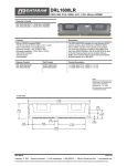
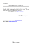
screenprintexpress.com
User Manual SPE-9600R and SPE-12800L quartz flash dryer
The SPE-9600R (and SPE-12800L) is a specialized quartz flash dryer
developed to increase production and decrease energy usage for all
textile facilities. The SPE-9600R uses state of the art thermal deflectors
which optimize full heat output potential of each individual quartz
halogen lamp. Loaded with options to include: thermal deflectors, 3
separate selectable zones, foot pedal and
photo eye activation.
The SPE-9600R will provide a quality production run for every print shop.
For further information please visit us at screenprintexpress.com or
contact customer support at 574.457.6996 or via email at
[email protected]
screenprintexpress.com
POWER SPECIFICATIONS
SPECS
-Model: SPE-9600L
-Max Cure Area 18”x20” (18” x 24” SPE-12800L)
-Dual Fan Cooling
Power Consumption
-240 Single Phase
-Initial Amp Draw 40 running Amp 28 (50 Initial Amp Draw/ Running amp 38 SPE1280L)
(REQUIRES A MIN 30AMP PLUG NOT SUPPLIED)
-Open lead wire for easy installation
Wire diagram/ Installation
WHITE: POWER 110/120 VOLTS
BLACK: POWER 110/120 VOLTS
GREEN: GROUND/ NEUTRAL
*WARRANTY WILL BE VOIDED IF INSTALLED INCORRECTLY. CERTFIED
ELECTRICTIAN RECOMMENDED*
Installation
The SPE-9600R quartz flash dryer comes complete and minor assembly is required.
1. There are four (4) base plate nuts (size 11mm) and four (4) washers that must be
secured prior to use. Simply tighten the nuts to the screw leads from the upper base
plate to the height adjustment shaft.
2. There are four (4) lead screws (5/32 wrench) and four (4) nuts (size 11mm)
included to secure the height adjustment shaft to the lower base plate (lower base
plate is the “H” frame that includes the wheels).
3. After securing the adjustable height shaft the height adjustment knob will need
to be secured to the lead screw using a #4 wrench. Total height adjustment is 14”
please contact for custom additional height adjustment. This completes the
installation process.
For questions contact us at 574.457.6996 or [email protected]
2
screenprintexpress.com
OPERATION
The SPE-9600R quartz flash dryer is a sophisticated unit and should be operated
under a controlled known environment.
After professionally wiring the unit into a power source, please follow the guidelines
below for proper usage.
1. To power up the unit simply select the “ON” position located on the right side of
the control panel.
2. To set the appropriate time use the center dial and simply turn to desired time
length in 1 second increments.
3. Select the desired amount of lamps to be used on the left side of the control
panel noted by a “Z.” Turn each zone to the “ON” position for maximum curing.
4. To select foot pedal operation simply plug the foot pedal into the left side panel
noted “FOOT PEDAL.” *Foot pedal will only function with the photo eye in the “OFF”
position.
5. To select photo eye sensor operation simply plug the photo eye into the right side
panel noted “PHOTO EYE.” Then turn the switch to the “ON” position. The photo
eye must be lined up with the supplied magnetic reflector both can be placed on
either the left or right side of the unit.
*Foot pedal will NOT function with the photo eye turned “ON.”
6. Height adjustment is made possible using the knob located in the center of the
base at the bottom of the height adjustment shaft. Turn the knob left or right to
establish the appropriate height off platen.
3
screenprintexpress.com
LAMP REPLACEMENT
Lamp Removal
1.
2.
3.
4.
5.
6.
7.
Turn unit "OFF"
Disconnect the unit from the main power source
Remove the qty. 4 1/4-20 button head bolts securing the hood to the aluminum light rails
Remove the high temp insulating tape securing the wires together
Remove the high temp ceramic lead wire retainers
Slide the wire through the retaining hole on the aluminum light rail
Slide the lamps from one side of the light rail passing through to the other side and remove
Lamp Installation
1. Slide new lamp continuously through one side passing through both ends of the aluminum
light rail
2. Run lead wires from the lamp continuing through the retaining hole on the aluminum light
rail
3. Reconnect the lead wire from the lamp to the supply wire using the high temp ceramic wire
retainers
4. Using the high temp ceramic tape re-secure the lamp wires together along with the supply
wire
5. Re-install the main hood taking note that all ceramic insulators are pushed in and clear
6. Re-secure the qty.4 1/4-20 button head bolts
7. Plug unit back into main power source
8. Turn unit to the "On" position
9. Test unit and run
4
screenprintexpress.com
Warranty and Disclosure
All parts both internal and external are covered with the unlimited warranty
program for 90 days from original date of purchase. Simply contact us for parts or
wiring diagrams directly at [email protected]
Operation outside of what is deemed normal usage
will null and void any implied warranty.
screenprintexpress.com
5