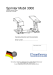
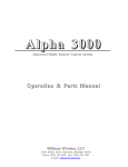
1
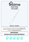
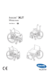
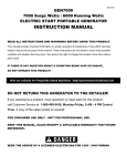
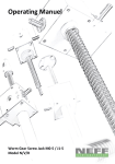
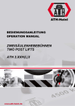
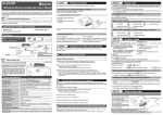
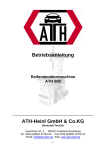
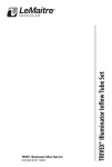
USER´S MANUAL
ATH DSH3000F2
ATH DSH3000FI2
® Copyright ATH-Heinl GmbH & Co. KG, 2012, All rights reserved. / Misprints and technical changes reserved / Issue: 07/2013
1
CONTENT
INTRODUCTION............................................................................................................ Fehler! Textmarke nicht definiert.
General information ................................................................................................... Fehler! Textmarke nicht definiert.
Description of lift ............................................................................................................................................................... 4
Main components ............................................................................................................................................................. 4
Operation ........................................................................................................................................................................... 5
Technical data .................................................................................................................................................................. 6
Scope of delivery .............................................................................................................................................................. 9
INSTALLATION .................................................................................................................................................................. 10
Foundation ...................................................................................................................................................................... 10
Place of installation ........................................................................................................................................................ 12
Assembly ......................................................................................................................................................................... 13
OPERATION ....................................................................................................................................................................... 16
Safety instructions .......................................................................................................................................................... 16
Operation instructions ................................................................................................................................................... 17
Utilization ..................................................................................................................... Fehler! Textmarke nicht definiert.
MAINTENANCE ................................................................................................................................................................. 19
Troubleshooting .......................................................................................................... Fehler! Textmarke nicht definiert.
Maintenance plan ........................................................................................................................................................... 21
Lubrication plan .............................................................................................................................................................. 22
Maintenance- and service instructions ....................................................................................................................... 22
DECLARATION OF CONFORMITY ............................................................................................................................... 25
SPARE PART BOOK ........................................................................................................................................................ 26
APPENDIX .......................................................................................................................................................................... 39
Electric diagram .............................................................................................................................................................. 39
Hydraulic diagram .......................................................................................................................................................... 40
WARRANTY NOTE ........................................................................................................................................................... 41
CHECKING BOOK............................................................................................................................................................. 43
NOTES................................................................................................................................................................................. 56
® Copyright ATH-Heinl GmbH & Co. KG, 2012, All rights reserved. / Misprints and technical changes reserved / Issue: 07/2013
2
Introduction
General Information
THE USER OF THE LIFT
IFT HAVE TO READ AND UNDERSTOOD THESE MANUAL:
ALL LIABILITY IS EXCLUDED FOR DAMAGES WHICH RESULT FROM NON-COMPLIANCE
NON COMPLIANCE OF THESE
INSTRUCTIONS
WE WILL NOT ASSUME ANY LIABILITY CAUSED
CAUSE BY NON-COMPLIANCE
COMPLIANCE WITH SAFETY NOTICES
Note: Follow the instructions to
o prevent personal injury or damage
Hint: Gives additional information on
on features and tips for efficiently using of the device.
® Copyright ATH-Heinl
Heinl GmbH & Co. KG, 2012, All rights reserved. / Misprints and technical changes reserved / Issue: 07/2013
3
Description of lift
Main components
1.
Lifting platform (P1)
2.
Lifting platform (P2)
The platforms are raised by the inner hydraulic cylinder and the scissor principle.
The hydraulic safety device prevents an accidental lowering of the lift.
3.
Extensions
Enables an extension of the lifting platforms
4.
Basic frame
For fixing the lift
5.
Lower scissor pair
6.
Upper scissor pair
7.
Main cylinder
8.
Secondary cylinder
9.
Hydraulic aggregate with control box (deadman system)
Herewith the hydraulic oil in the tank will be piped via a gear pump, which is driven by the motor, to the
cylinder. With a lowering valve the oil will be piped back into the tank.
10.
CE-Stop and limit switch
The CE-Stop stops the lift while lowering at a height of 500 mm.
The limit switch stops the lifting at reaching the max. lifting height and protects with that the hydraulic
system.
® Copyright ATH-Heinl GmbH & Co. KG, 2012, All rights reserved. / Misprints and technical changes reserved / Issue: 07/2013
4
Operation
1. Lockable main switch with emergency stop function
for switching on and off the lift and as security against an use of unauthorized persons.
2. Display of operation
Indicates that the lift is switched on.
Indicates that the limit switch is reached.
Indicates that the CE-Stop was activated.
Indicates that the motor works.
Indicates that the lift is in the final lowering process.
Indicates that there is an error or a malfunction in the electrical system.
3. Buzzer
gives an acoustic an visual signal after reaching the CE-Stop
4. Button LIFTING
5. Button LOWERING
6. Button for bridging the limit switch
suitable for bleeding the hydraulic cylinder
7. Button for bridging the light barrier
enables an adjustment of the synchronization
® Copyright ATH-Heinl GmbH & Co. KG, 2012, All rights reserved. / Misprints and technical changes reserved / Issue: 07/2013
5
Technical data
® Copyright ATH-Heinl GmbH & Co. KG, 2012, All rights reserved. / Misprints and technical changes reserved / Issue: 07/2013
6
Type
ATH DSH 3000F2
ATH DSH 3000FI2
Capacity
3.000 kg
Lifting time
50 s
Lowering time
50 s
Electric system
3/400V/50Hz
Voltage
DC24V
Motor
2,6 KW
Revolution per minute
1.375 U/min
Fuse protection
3 C 16 A
Connection cables
Min. 5 x 1,5mm²
Protection type
IP 54
Working pressure ²
Recommended
hydraulic-oil
125 -145 bar
Sommer: H-LPD 32 (z.B.: OEST H-LPD
LPD 32 DD L)
Winter: H-LPD 22
Oil quantity
Floor anchoring
scissor pair
Floor anchoring
control box
Floor anchoring driveover sheet
8 Stück
4 Stück
16 Stück
Noise level
≤ 75 dB (A)/lm
Weight
²
830 kg
The already factory-set
set hydraulic working pressure is adjusted to the maximum rating. The setting of the pressure
control valve may not be changed. Any changes to the settings can cause serious damages. If nominal load can
not be lifted please contact our service team..
team.
® Copyright ATH-Heinl
Heinl GmbH & Co. KG, 2012, All rights reserved. / Misprints and technical changes reserved / Issue: 07/2013
7
Load distribution
Q
P1
P2
Load distribution
²
Total weight of vehicle
Max 2/5 x Q
Max 3/5 x Q
2/3
At bigger distances the load capacity will be reduced. In this case and in other cases, which are not covered by
this manual the manufacturer should be contacted.
Min
Max
A
1.900 mm
4.000 mm
B
100 mm
C
D
1.900 mm
900 mm
® Copyright ATH-Heinl
Heinl GmbH & Co. KG, 2012, All rights reserved. / Misprints and technical changes reserved / Issue: 07/2013
8
Scope of delivery
2
1
2
1
Packages with scissors:
Dimension (L x W x H): 1.570 x 580 x 200 mm
Weight:
Package with control box, hydrauli
ydraulic- and pneumatic hoses:
Dimension (L x W x H): 400 x 540 x 1.140 mm
Weight:
Packages with ramps
Dimension (L x W x H): 500 x 340 x 120 mm
Weight:
Package with drive-over plates
Dimension (L x B x H):
Weight:
If anything is missing in the delivery please contact our sales department!
Transportation and storage:
- Lift with care, using suitable means of support for the load, in perfect working order and using the special hooking
point.
- Avoid sudden jolts and tugs, watch out for uneven surfaces, bumps etc.
- After removing the packing, check that they are taken to special waste collecting areas inaccessible to children
and animal as long as they are not disposed.
Warehouse temperature: -25°
- C ~ +55 °C
® Copyright ATH-Heinl
Heinl GmbH & Co. KG, 2012, All rights reserved. / Misprints and technical changes reserved / Issue: 07/2013
9
INSTALLATION
Foundation
for ATH DSH3000F2
® Copyright ATH-Heinl GmbH & Co. KG, 2012, All rights reserved. / Misprints and technical changes reserved / Issue: 07/2013
10
for ATH DSH3000FI2
® Copyright ATH-Heinl GmbH & Co. KG, 2012, All rights reserved. / Misprints and technical changes reserved / Issue: 07/2013
11
C20/25
Min. 20 days
10 mm
Concrete quality:
Concrete curing time:
Max. incline:
If soils do not comply with the requirements, there can evoke serious injuries to personal or damages to the lift.
Do not install the lift on asphalt or soft concrete floor.
There must be no expansion joints or cuts,
cuts, which will break the continuity of the upper reinforcement.
Load capacity of intermediate ceilings must be checked by operator.
Place of installation
B1
L1
H
1.000 mm
appr. 2.800 mm
appr. 4.000 mm
B2
L2
1.000 mm
appr. 2.800 mm
Allowed working temperature:
10-50 °C
Max. allowed humidity:
≤80% bei 30 °C
Height above sea level:
≤2000m
Power connection and ground cable (see technical data) is to be made in form of a plug device (socket and plug ) or a
fixed connection.
Necessary supply lines
See technical data
The lift is designed for an installation in dry rooms. The installation in wet rooms as well as rooms with a risk of
explosion is not allowed.
® Copyright ATH-Heinl
Heinl GmbH & Co. KG, 2012, All rights reserved. / Misprints and technical changes reserved / Issue: 07/2013
12
Assembly of lift
This manual is not to be seen as an assembly instruction, but only as a help and advice for skilled personal. For
the following works are necessary the adequate clothes and safety equipments. An incorrect installation and
adjustments causes disclaimer
sclaimer of warranty.
warranty
1. Positioning and alignment
a. By means of chalk the position for the installation can be marked before.
before
b. Pay attention to the drive-on
on direction while positioning the scissors.
scissors
c. Position the control box as indicated in the technical data.
data
2. Fixing with safety anchors:
a. Bore holes and pay attention to the
necessary boring depth A and boring
diameter of the anchor manufacturer
b. Clean the inner oft he holes
c.
d. Tight the nuts
nut with the torque specified by
the manufacturer.
Thickness B depends on floor cover.
cover
Put the anchors into the holes until the
needed depth is reached.
3. Hydraulic connection
a. First open the front cover of the control box
b. Install the hydraulic hoses as shown below.
below
Retight all hydraulic connections.
Make
ake sure that no movable parts can damage the hydraulic hoses.
hoses
® Copyright ATH-Heinl
Heinl GmbH & Co. KG, 2012, All rights reserved. / Misprints and technical changes reserved / Issue: 07/2013
13
4. Hydraulic oil
a. Fill in hydraulicc oil until the mark.
mark
5. Electrical connection
Herewith the general as well as the local regulations have to be observed. Therefore only skilled personal are
ar
allowed to make this work.
Pay attention to the necessary power supply (see technical data).
6. Check before first lifting
a.
b.
c.
d.
e.
f.
the
he tightness of all screws, nuts and so on
the
he leak tightness of connections and cylinders, retight if necessary
the function of all buttons
the
he correct rotating direction of motor
bleed the hydraulic circuit as desbribed in chapter maintenance
At the first lifting lubricate the sliding guide of the scissor arms (lubrication type see in the lubrication
l
plan)
® Copyright ATH-Heinl
Heinl GmbH & Co. KG, 2012, All rights reserved. / Misprints and technical changes reserved / Issue: 07/2013
14
7. Correct adjustment of limit switch
a.
b.
c.
d.
e.
f.
Position the lift at a height of 1.900 mm for adjusting the max. llifting height
Loosen the nuts (3) of the limit switch and adjust it
Retight the nuts (3) again
Position the lift at a height of 400 mm for adjusting the CE-Stop
CE
Loosen the nuts (3) of the limit switch and adjust it
Retight the nuts (3) again
8. Lifting under load
a. Lift a load to a height of appr. 1.000 mm and check the synchronization,
synchronization readjust if necessary.
necessary
b. During further lifting keep on watching the synchronization.
synchronization
c. Lower the load and install the still missing covers resp. ramps
9. Fill in the enclosed checking book after positioning the lift.
lift
This information will be needed in case of a possible service case.
case
® Copyright ATH-Heinl
Heinl GmbH & Co. KG, 2012, All rights reserved. / Misprints and technical changes reserved / Issue: 07/2013
15
OPERATION
Safety instructions
1. Pay attention to the correct load
distribution of the vehicle
2. It is not allowed to make any
modifications on the lift
3. Leave the danger zone while
lowering the lift
4. The danger zone must be kept free
while lifting and lowering
5. In case of the vehicle drop down
immediately leave the danger zone
6. Avoid heavy swinging movements
of the lifted vehicle
7. A moving of the vehicle on the lift is
not allowed
8. Only skilled personal is allowed to
operate the lift
9. Use a protection against rolling
down
10. Only authorized persons are
allowed to enter the danger zone
11. For a secure working a proper
maintenance and inspection is
necessary
12. Read and understand the user´s
manual before operate the lift
13. Do not work with damaged lifts
Damaged danger symbols have to be replaced.
replaced
® Copyright ATH-Heinl
Heinl GmbH & Co. KG, 2012, All rights reserved. / Misprints and technical changes reserved / Issue: 07/2013
16
BTR-Nr. 0030
18.12.2012
Operation instructions
Application and activities
APPLICATION
VEHICLE LIFT
DANGER FOR HUMAN AND ENVIRONMENT
•
•
•
•
•
•
•
•
•
•
•
•
•
Issue:
signed on:
Dezember 2010
10.12.2012
Falling down of load or parts
Crush injuries during movement of lift and/or parts
If system leaks it is possible that hydraulic oil gets into the environment
PRECAUTION AND RULES OF CONDUCT
Observe the user´s manual
Watch the lift
Operation only by skilled personal
Avoid positions with no means of escape in case of danger
Keep in mind the maximum capacity of the lift
Secure the vehicle against rolling away
Check the functions daily before operation
Do not put persons at risk during movement of lift
Do not carry persons on the lift
Leave the danger zone during lifting and lowering
BEHAVIOUR IN CASE OF ERROR AND DANGER
•
•
•
•
•
•
•
•
•
•
•
In case of security relevant errors stop immediately the operation and secure it against use.
Inform responsible person in case of defects.
Remedy of deficiencies only by experts.
BEHAVIOUR IN CASE OF ACCIDENTS – FIRST AID
Secure the scene of accident.
Render first aid, inform first-aider and your boss.________________
Take care of the person injured.
Place of first aid kit and first aid book:
________________
EMERGENCY CALL:
________________
Record all information in the first aid book
MAINTENANCE; DISPOSAL
Maintenance works on the lift are made by: ________________
Responsible for disposal (e.g. used oil): ________________
® Copyright ATH-Heinl GmbH & Co. KG, 2012, All rights reserved. / Misprints and technical changes reserved / Issue: 07/2013
17
Utilization
The product is intended for lifting of vehicles. The corresponding technical data
data have to be observed.
1. Preparation
a.
Read all safety instructions carefully before operating the lift.
lift
b. Lower the lift completely
c. Position the vehicle centrical between the scissors, pay attention herewith to the load distribution.
distribution
d. Put the rubber discs CENTRICAL under the original lifting points of the vehicle.
vehicle
2. Lifting
a.
b.
c.
d.
Switch on the lift with the main switch
Lift the vehicle up to a height of 100-150
100 150 mm and stop the lifting by releasing the button LIFTING
Check if the vehicle is secure on the lift
Following
owing lift further and observe the lifting process
3. Lowering
a. Check before lowering if there are any obstacles under the car
b. Press the button LOWERING
c. After reaching athe CE-Stop
Stop the button LOWERING must be released and then pushed again.
agai
4. Completion
a. Lower the lift completely
b. Remove the rubber discs
c. Drive the vehicle from the lift
® Copyright ATH-Heinl
Heinl GmbH & Co. KG, 2012, All rights reserved. / Misprints and technical changes reserved / Issue: 07/2013
18
MAINTENANCE
Reparation works are only allowed to be done by authorized service partners or, after contacting ATH, by the client.
Before maintenance and reparation works the lift must be disconnected from the electrical supply (main switch
off, disconnect plug). Suitable precautions must be made against a re-start.
re
Works on the electrical parts of the lift respectively on the supply lines are only allowed to be done by experts/electricians.
exper
Troubleshooting
Error
Lift does not work
Possible reason
Remedy
Main switch is off.
Switch the lift on
Check the power supply, if necessary
repair it
Replace
Check the switches and connections, if
necessary replacing
There is no electrical
electric connection
Fuses are burned
A limit switch is defect
No lifting
Wrong rotating direction of the motor
Not enough oil in the hydraulic circuit
Button LIFTING
L
does not react
Lowering valve does not close
The emergeny dumping screw closes
not properly
Filter on the pump is dirty
Obstacle between light sensor
Reflector of light sensor is defect
Scissor platforms have not the same
height
Light barrier is not positioned correctly
Change two phases on the main
switch
Fill needed hydraulic oil (lift must be
lowered)
Check the button and connection, if
necessary replacing
Check and clean the lowering valve, if
necessary replacing
Tighten the screw
Check and clean
Remove the obstacle
Replace the reflector
Restore the synchronization
Re-establish
establish the correct position
No lowering
Control board defect
Electromagnet on the lowering valve
has no function
Lowering valve does not open
Button LOWERING defect
Obstacle between light sensor
Reflector of light sensor is defect
Scissor platforms have not the same
height
Light barrier is not positioned correctly
Replace control board
Check the function, if necessary
replace
Chec the lowering valve if it reacts, ifi
necessary replace
Check the button, if necessary replace
Remove the obstacle
Replace the reflector
Restore the synchronization
syn
Re-establish
establish the correct position
Lift does not stop at CE-Stop
Limit switch (CE-Stop)
(
is wrong
adjusted resp. defect
Check the adjustment of the limit
switch. In case of a defect limit switch
replace
place it.
it
Water or air in hydraulic circuit
Bleed hydraulic circuit
Lift does not raise synchronical
Damaged cylinder sealings
Check and if necessary replace
® Copyright ATH-Heinl
Heinl GmbH & Co. KG, 2012, All rights reserved. / Misprints and technical changes reserved / Issue: 07/2013
19
Lift does not raise the indicated load
Not enough hydraulic oil
Pump is defect
Pressure control valve wrong adjusted
Check oil level (lift is lowered), if
necessary refill
Check the pump, if necessary replace
Adjust correctly
Lift raises or lowers jerkily
Leakage, water or air in hydraulic
circuit
Filter of the pump is dirty
Pump sucks air
Bleed the hydraulic system. If
necessary eliminate leakage
Check and clean if necessary
Check the sealing and replace if
necessary
Lift does not stop at the max. height
Limit switch is wrong adjusted resp.
defect
Check adjustment of limit switch
Replace a defect limit switch
® Copyright ATH-Heinl GmbH & Co. KG, 2012, All rights reserved. / Misprints and technical changes reserved / Issue: 07/2013
20
Maintenance plan
Interval:
Components:
Check:
Rubber discs
Wear and deformation
Lift
Obvious damages
Lift
Cleanness
Hydraulic
Leak-tightness
Safety devices
Obvious damages
Paintwork
Scratches (Danger of corroision)
Air cylinder
Function and wear
Cylinder
Function and wear
Monthly
Anchor bolts
Torque (acc. manufacturer)
Quarterly
Axes and safety notches
Wear and cleanness
Cylinder (dust sealing)
Wear and deformation
Hydraulic circuit
Wear and leakage
Hydraulic pump
Unusual noise
Electrical components
Damages
Hydraulic oil
Check oil level and, if necessary, refill
Dirt or oil aging
Cylinder sealing
Oil loss and deformation
Main check (by expert)
All components are checked for damages
Hydraulic oil
Exhange
Hydraulic system
Cleaning
Hoses
Exchange
Every day
Weekly
Half-yearly
Yearly
Every 3 years
(recommended)
Every 6 years
® Copyright ATH-Heinl GmbH & Co. KG, 2012, All rights reserved. / Misprints and technical changes reserved / Issue: 07/2013
21
Lubrication plan
Interval:
Components:
Grease type
Monthly
Sliding guides
Multi
Multi-purpose
grease
Quarterly
Axes
Mult
Multi-purpose
grease
Maintenance- and service instructions
Check oil level
1. Lower the lift completely
2. Remove tank cap
3. Check the oil level on the tank cap
Exchanging oil
1. Lower the lift completely
2. Remove the oil filling screw
3. Remove carefully
ly the oil drain screw and drain the oil into a suitable recipient
Clean the tank and oil filter to avoid an early pollution of the hydraulic oil.
4. After the complete draining of the oil close the tank with the oil drain screw
5.Fill the new oil into the oil tank
6. Lift and lower the lift and check, if the max. height is still correct. If necessary refill carefully
The used oil must be disposed in consideration of all legal regulations.
® Copyright ATH-Heinl
Heinl GmbH & Co. KG, 2012, All rights reserved. / Misprints and technical changes reserved / Issue: 07/2013
22
Bleeding of hydraulic system
1. After the first filling with hydrauli oil the button
LIFTING must be pressed for appr. 30 seconds for
pumping the oil into the hydraulic system.
2. Raise the lift until the max. lifting height. (this height
is not allowed to be over 1.900 mm!!)
3. Open the upper cover of the control switch and
press the button for bridging the limit switch (6)
and the button for bridging the light barrier (7) for a
few seconds until both scissor platforms are at the
same height.
4. Lower the lift completely by pressing the button
LOWERING.
5. Repeat the lifting and lowering process at least
twice times more.
Emergency lowering in case of power breakdown
1. Switch the lift off with the main switch and secure it
agains a restart.
2. Open the front cover of the control box
3. Loosen the screw of the safety valves (A) by
turning counterclockwise
4. The lowering of the lift will be activated by
loosening the screw of the lowering valve (B).
!!! ATTENTION: With this screw the lowering speed
can be adjusted!!!
5. After the complete lowering of the lift all screws
must be retightened again.
® Copyright ATH-Heinl GmbH & Co. KG, 2012, All rights reserved. / Misprints and technical changes reserved / Issue: 07/2013
23
Adjustment of the valve for lowering speed
Accelerating of the lowering speed by turning the
screw of the lowering valve (B)
COUNTERCLOCKWISE.
Decelerating of the lowering speed by turning the
screw of the lowering valve (B) CLOCKWISE.
® Copyright ATH-Heinl GmbH & Co. KG, 2012, All rights reserved. / Misprints and technical changes reserved / Issue: 07/2013
24
DECLARATION OF CONFORMITY
Seriennummer / Serial number:
Konformitätserklärung
Declaration of conformity
Déclaration de conformité
Declaración de conformidad
Für / for / pour / para
KFZ-Hebebühne
Car-lift
Ponts élévateurs
Elevador
Typ / Type / Type / Tipo
ATH DSH 3000F2
ATH DSH 3000FI2
Wurden folgende einschlägige Bestimmungen beachtet
The following EG-directives are considered
Les Directives suivantes de l’Union européenne ont été respectées
Los siguientes directivas pertinentes de la Unión Europa fuen cumplido
2006/42/EC (Machine-Directive)
Folgende harmonisierten Normen und Vorschriften wurden eingehalten
The following harmonized standards are applied
Les normes harmonisées suivantes ont été appliquées
Los siguientes normas y reglamentos armonizados fuen cumplido
DIN EN 1493:2010 (Machine-Directive)
DIN EN 60204-1: 2006+A1:2009 (Low voltage directive)
ATH-Heinl GmbH &Co. KG
Kauerhofer Straße 2
D-92237 Sulzbach-Rosenberg
Germany
Hersteller
Manufacturer
Fabricant
Fabricante
CCQS UK Ltd.,
Level 7, Westgate House, Westgate Road,
London W5 1YY UK
ENGLAND
Prüfinstitut
Institut of Quality
Institut de qualité
Instituto de calidad
Referenznummer der technischen Daten:
Reference number for the technical data:
Numéro de référence des données techniques:
Número de referencia de los datos técnicos:
TF-C-0106-12-02-16-5A
Nummer des Zertifikats:
Number of the certificate:
Numéro du Certificat
Número del certificado
CE-C-0106-12-02-16-5A
Hiermit wird bestätigt, dass die oben bezeichneten Maschinen den genannten EG-Richtlinien entsprechen.
Herewith we confirm that the above named machines are according to the named EC-directives.
Nous certifions par la présente la conformité des machines décrites ci-dessus aux Directives de l’Union européennes citées.
Confirmamos con esto de que la mercancía denominada arriba cumple las directivas llamadas de la Unión Europea.
ATH-Heinl GmbH &Co. KG
Kauerhofer Straße 2
D-92237 Sulzbach-Rosenberg
Germany
Im April 2012
ATH-Heinl GmbH & Co. KG/ Hans Heinl (Geschäftsführer)
® Copyright ATH-Heinl GmbH & Co. KG, 2012, All rights reserved. / Misprints and technical changes reserved / Issue: 07/2013
25
SPARE PART BOOK
® Copyright ATH-Heinl GmbH & Co. KG, 2012, All rights reserved. / Misprints and technical changes reserved / Issue: 07/2013
26
® Copyright ATH-Heinl GmbH & Co. KG, 2012, All rights reserved. / Misprints and technical changes reserved / Issue: 07/2013
27
#
ART.#
1
2
3
YA-B1TG01
YA-B1TG02
YA101298.02
YA101298.01
7230D13000
606033
4
5
6
#
DESCRIPTION
LIFT
Platform P1
Platform P2
Cover for hydraulic hose
REMARK
1
1
3
Cover for hydraulic hose
HBP6021/HBP6023
HGA8407
Control unit
Rubber block
1
115X100X55
® Copyright ATH-Heinl GmbH & Co. KG, 2012, All rights reserved. / Misprints and technical changes reserved / Issue: 07/2013
28
x
1
8
® Copyright ATH-Heinl GmbH & Co. KG, 2012, All rights reserved. / Misprints and technical changes reserved / Issue: 07/2013
29
Art #
1
2
3
4
5
6
7
8
9
10
11
12
13
14
15
16
YA10-1283
YA10-1284TG
YA10-1285
YA10-1286T
YA10-1287TG
YA10-1308BG
YA20-0472
YA20-0473
YA20-0473B
YA20-0474
YA20-0478
YA20-0479
210008
YA20-0480
210015
204041
17
18
19
20
21
22
23
24
25
26
27
212004
210041
211003
YA-FBT
YA20-0476T
212005
YA10-1530BT
YAY-70-0
YAY-60-0
YA20-0362B
206024
28
29
30
31
32
33
34
35
36
37
38
201039
YA10-1536B
33M-C400
507001
YA20-0481T
YA10-1288
YA20-0483
210043
YA20-0592
210039
204041
39
40
41
42
43
44
45
YA20-0477
210040
YA20-0615T
211019
YA20-0593
210042
204021
PLATFORM P1
Base frame
Lower – innter scissor part
Lower – outer scissor part
Upper – outer scissor part
Upper – inner scissor part
Platform
Shaft
Nylon sliding guide below
Nylon sliding guide above
Shaft
Shaft
Shaft
Copper bushing
Shaft
Copper bushing
Nut
HSW3210
HGS3150
HGS3152
HSW3211
HSW3212
HSW3214
HLB3030
HSM2001
Seeger ring
Copper bushing
Seeger ring
Reversing lever complete
Shaft for cylinder support below
Seeger ring
Ramp
Main hydraulic cylinder
Secondary hydraulic cylinder
Nut
Screw
HMB2520
HSR2315
HWZ2310
HSR2317
631008
HHZ6150
HHZ6152
HSM8538
HSM2001
Screw
Extension
Support for light barrier
Light barrier
Nylon distance holder
Reversing lever arm
Bushing
Copper bushing
Shaft
Copper bushing
Nut
HWZ2312
HMB3015
HBS8610
HSR2308
HSW3216
HMB3015K
HSM2515
Shaft for cylinder support above
Copper bushing
Washer
Seeger ring
Shaft
Copper bushing
Nut
HHL8433
HLS8433
HAH3110
HAB3010
HMB4025
HSW3215
2520
3030
M20X1 GT/T812
D.25 - GB/T894.2
2520
D.19 - GB//T896
D.20 - GB/T894.2
M5X10 GB/T818
M8X45
4025
2515
M20X1 GB/T6184
3015
D.24 - GB/T896
3015
M25X1.5 GB/T6184
® Copyright ATH-Heinl GmbH & Co. KG, 2012, All rights reserved. / Misprints and technical changes reserved / Issue: 07/2013
30
1
1
1
1
1
1
4
2
2
2
1
2
12
1
2
3
6
10
4
1
2
4
2
1
1
1
2
1
1
1
1
1
2
1
2
1
2
2
1
2
2
2
2
2
2
® Copyright ATH-Heinl GmbH & Co. KG, 2012, All rights reserved. / Misprints and technical changes reserved / Issue: 07/2013
31
Art #
1
2
3
4
5
6
7
8
9
10
11
12
13
14
15
16
17
18
19
20
21
22
23
24
25
26
27
28
29
30
31
32
33
34
35
36
37
38
39
YA10-1283
YA101284TG
YA10-1285
YA10-1286T
YA101287TG
YA10-B11G
YA20-0472
YA20-0473
YA20-0473B
YA20-0474
YA20-0478
YA20-0479
210008
YA20-0480
210015
204041
212004
210041
211003
YA-FBT
YA20-0476T
212005
YA101530BT
YAY-70-0
YAY-60-0
YA10-2002T
YA10-2003T
YA10-2001T
206024
202005
205002
203002
208002
202006
505002
YA10-2004T
206030
33M-C400
507019
HSW3210
HGS3150
HGS3152
HSW3211
HSW3212
HSW3214
HLB3030
HSM2001
HMB2520
HSR2315
HWZ2310
HSR2317
631008
PLATFORM P2
Base frame
Lower – innter scissor part
1
1
Lower – outer scissor part
Upper – outer scissor part
Upper – inner scissor part
1
1
1
Platform
Shaft
Nylon sliding guide below
Nylon sliding guide above
Shaft
Shaft
Shaft
Copper bushing
Shaft
Copper bushing
Nut
Seegering
Copper bushing
Seeger ring
Reversing lever complete
Shaft for cylinder support below
Seeger ring
Ramp
1
4
2
2
2
1
2
12
1
2
3
6
10
4
1
2
4
2
HHZ6150
HHZ6152
HRA2510
HRE2510/ HRE2812
Main hydraulic cylinder
Secondary hydraulic cylinder
Ring support
Ring for limit switch
Holder for limit switch
Screw
Screw
Washer
Nut
Lock washer
Screw
Limit switch
U-Bolt
Screw
Support for light barrier
Light barrier
HES8413
HHL8433
HLS8435
2520
3030
M20X1 - GT/T812
D.25 - GB/T894.2
2520
D.19 - GB//T896
D.20 - GB/T894.2
M5X10 - GB/T818
M4X25 - GB/T70.1
D.4 - GB/T97.1
M4 - GB/T6170
D.4 - GB/T93
M4X30 - GB/T70.1
® Copyright ATH-Heinl GmbH & Co. KG, 2012, All rights reserved. / Misprints and technical changes reserved / Issue: 07/2013
32
1
1
2
2
2
4
4
4
4
4
4
2
2
2
1
1
® Copyright ATH-Heinl GmbH & Co. KG, 2012, All rights reserved. / Misprints and technical changes reserved / Issue: 07/2013
33
1
2
3
4
5
6
7a
BZ-YK2Y-N
505022
502053
502052
502021
507002
504009
Art #
HBT8254
HSG7110
HKL8256
HSE7216
CONTROL UNIT
Hydraulic aggregate
Main switch
Button LOWERING
Button LIFTING
Buzzer
Connection block
Fuse
7b
504013
HSH8258
Fuse
8
9a
9b
10
11
12
501044
503066
503072
504016
504004
502017
HMS8259
HLT8264
Motor contactor
Transformer
Transformer
Fuse
Fuse
Bridging buttons
13
14
507038
507011
HSP8268
HSL8264
Control board
Display
HHS8253
HSS8261
HZ5/2-20A
LA37G-EA21-11
LA37G-EA21-10
DC24V
380V/400V 16A/10X38
220V/230V 32A/10X38
1210/DC24V
80VA 220/380V
80VA 230/400V
1A 5X20
4A 5X20
LA16Y-11-Y
CP-501B.1
CP-501D
® Copyright ATH-Heinl GmbH & Co. KG, 2012, All rights reserved. / Misprints and technical changes reserved / Issue: 07/2013
34
1
1
1
1
1
1
3
2
1
1
1
3
1
1
(2)
1
1
® Copyright ATH-Heinl GmbH & Co. KG, 2012, All rights reserved. / Misprints and technical changes reserved / Issue: 07/2013
35
Art #
HHB8301
HHD8331
HRV8318
HKD8322
HDV8315
HHA8308
HBS8712
HFR2832
HSS0665
HSS0820
HFR2812
HMF8303
HYDRAULIC AGGREGATE
Hydraulic block
O-Ring
Non-return valve
Copper disc
Pressure control valve
Blind bolt
Washer
Lock washer
Screw
Screw
Lock washer
Motor flange
Motor
1
2
3
4
5
6
7
8
9
10
11
12
13a
BZ-ZB-Y
309054
307067
302018
307010
BZ-SD-01
205006
208005
202036
202045
208006
BZ-DJ-1B
509070
13b
509075
Motor
13c
509039
Motor
13d
13e
13f
14
15
16
17
18
19
509071
509068
509092
BZ-ZT24
209042
305054
306079
302005
BZ-WYK2Y
203004
213032
309019
305001
307006
307048
Motor
Motor
Motor
Motor adapter
Screw
Manometer
Connection
Connection
Hydraulic distributor
20
21
22
23
24
25
26
27
28a
28b
29
30
31
32
33
34
35
36
305018
BZ-BJ36
301015
301008
BZG14X200
BZG14X120
BZG18X100
305010
HK2-0200
305026
202053
BZ-F-01
HMA8304
HHM8314
HHA8336
HHA8327
HSM0615
HHD8332
HBS6214
HVS8319
HMS8317
HAS8325
HPA8305
HPZ8311
HPZ8312
Nut
Screw
O-Ring
Blind bolt
Lowering valve
Elekctro magnet for lowering
valve
Blind bolt
Pump adapter
Pump
Pump
Oil return pipe
HAR8307
HHF8323
HAT8309
HTV8324
HAD8310
17.0X1.80 - GB3452.1
16X20
D.6 - GB/T97.1
D. 6 - GB/T93
M6X65 - GB/T70.1
M8X20 - GB/T70.1
D.8 - GB/T93
220V/380V/50HZ/3PH
2.6KW
230V/400V/50HZ/3PH
2.6KW
220V/380V/60HZ/3PH
2.6KW
220V/50HZ/1PH 2.2KW
230V/50HZ/1PH 2.2KW
220V/60HZ/1PH 2.2KW
M6X8 - GB/T80
400bar 1/4
1/4
1/4 (1BT-04SP)
1
1
1
1
1
1
1
1
1
2
1
M6 - GB/T6170
M6X160 - GB/T899
18X2.4 - GB1235
QD07
D.2.5
DC24V
4
4
2
2
1
3
3/8
2
1
1
1
1
4.8cc for 3PH motor
2.1cc for 1PH motor
Oil return pipe
1
Oil suction pipe
1
Oil filter
Oil tank
Tank cap with oil level indicator
Screw
Sealing
3/8
3/8
M8X90 - GB/T70.1
® Copyright ATH-Heinl GmbH & Co. KG, 2012, All rights reserved. / Misprints and technical changes reserved / Issue: 07/2013
36
1
2
1
1
1
2
8
8
4
4
6
1
1
1
1
1
2
1
® Copyright ATH-Heinl GmbH & Co. KG, 2012, All rights reserved. / Misprints and technical changes reserved / Issue: 07/2013
37
1
2
3
23
24
25
26
27
28
YAY-70-0
YAY-60-0
7230ZZ210
7230ZZ195
7230ZZ180
7230ZW2870
7230ZZ1300
7230ZZ1400
7230ZW4200
306019
306019
306019
306081
303010
302005
YAY-70-10
YA-70-20
YAY-70-3
YA-70-4
YAY-70-5
YA-70-6
MS10080-8
307021
212005
312028
312014
309050
305006
29
30
31
32
33
34
35
36
37
38
310011
311016
313001
206024
YAY-60-10
YAY-60-3
YAY-60-5
312027
309032
310031
4
5
6
7
8
9
10
11
12
13
14
15
16
17
18
19
20
21
22
Art #
HHZ6150
HHZ6152
HZA8365
HHA8327
HHS8652
HZK8810
HZV8710
HZA8468
HYDRAULIC SYSTEM
Main hydraulic cylinder
Secondary hydraulic cylinder
Hydraulic hose
L=210
2
2
2
Hydraulic hose
L=195
2
Hydraulic hose
L=180
2
Hydraulic hose
L=2870
1
Hydraulic hose
L=1300
1
Hydraulic hose
L=1400
1
Hydraulic hose
L=4200
1
Hose
Hose
Hose
T-connection
90° connection
Connection
Cylinder tube of main cylinder
Oil hose
Piston
Piston rod
Top plate
Cylinder support above
U holding sheet
10X6.5 L=2300
10X6.5 L=900
10X6.5 L=3000
10
1/4 (1B9-04SP)
1/4 (1BT-04SP)
1
1
1
1
6
4
1
1
1
2
1
2
1
Non-return valve
Seeger ring
Sealing
O-Ring
O-Ring
Guide ring
1/4
D.20 - GB/T894.1
70X58X20.5
24X2.4 - GB1235
70X3.1 - GB1235
36X25X2.5 GB/T15242.2
36X46X6
36X44X5
1/4
M5X10 - GB/T818
1
2
1
2
1
2
HRV8512
HSR2317
HZD8892
HZD8692
HZD8507/HZD8558/HZD8677
HZD8758
HZK8687
HZV8698
HZD8722
HZD8712
HZD8699
Sealing
Scraper
Washer
Screw
Cylinder tube for secondary cylinder
Piston
Top plate
Sealing
O-Ring
Sealing
60X48X20.5
60X3.1 - GB1235
36X46X8
® Copyright ATH-Heinl GmbH & Co. KG, 2012, All rights reserved. / Misprints and technical changes reserved / Issue: 07/2013
38
1
2
2
2
1
1
1
1
1
1
APPENDIX
Electric diagram
QF
T
Power switch
Transformer 80VA
M
KM
YV2
YV3
SQ1
Safety solenoid valve
– P1
Lowering/final
lowering button
Top limit switch
JD
Beeper
SB2
SB4
SQ2
Motor
Contactor DC
Safety solenoid valve–
P2
Photocell pass-by
button
Safety height limit
switch
ST
YV1
SB1
Thermal relay
Lowering solenoid
valve
Lifting button
SB5
Override button
SQ3
Photocell
® Copyright ATH-Heinl GmbH & Co. KG, 2012, All rights reserved. / Misprints and technical changes reserved / Issue: 07/2013
39
Hydraulic diagram
1a
2b
4a
5
8
11
Platform P1 master
cylinder
Platform P2 slave
cylinder
Safety solenoid valve
– P2
Lowering control
valve
Gear pump
Pressure gauge
1b
3a
4b
6
9
Platform P2 master
cylinder
Parachute valve - P2
2a
Safety solenoid valve
– P1
Maximum pressure
valve
Motor
4c
3b
Platform P1 slave
cylinder
Parachute valve - P1
7
Lowering solenoid
valve
Oil filter
10
Non return valve
® Copyright ATH-Heinl GmbH & Co. KG, 2012, All rights reserved. / Misprints and technical changes reserved / Issue: 07/2013
40
GARANTIEKARTE/WARRANTY NOTE
Fachhändler Anschrift / Dealer address:
Kunden Anschrift / Customer address:
Fima (ggf. Kundennummer) / Company (evtl. Customer Number)
Fima (ggf. Kundennummer) / Company (evtl. Customer Number)
Ansprechpartner / Contact person
Ansprechpartner / Contact person
Straße / Street:
Straße / Street:
PLZ & Ort / ZIP code & Town:
PLZ & Ort / ZIP code & Town:
Tel. & Fax:
Tel. & Fax:
e-Mail:
e-Mail:
Hersteller & Modell/
Manufacturer & model
Seriennummer /
Serial number
Baujahr /
Year of manufacture
Referenz-Nummer /
Reference number
Beschreibung der Meldung / Description of the message:
Beschreibung der benötigten Ersatzteile / Description of required spare parts:
Ersatzteil / Spare part
Artikelnummer / Article number
Menge / Quantity
WICHTIGER HINWEISE / IMPORTANT NOTES:
Schäden, die durch unsachgemäße Handhabung, unterlassene Wartung oder mechanische Beschädigung entstehen, fallen nicht in die
Gewährleistung. Für Anlagen, die nicht durch einen zugelassenen Monteur der Fa. ATH montiert wurden, beschränkt sich die Gewährleistung auf die
Bereitstellung der erforderlichen Ersatzteile.
Damage caused by improper handling, lack of maintenance or mechanical damage, does not fall into the warranty. For machines that are not installed
by a licensed technician from the company ATH, the warranty is limited to the provision of necessary spare parts.
Transportschäden / Damages in transit:
Offener Mangel (Sichtbare Transportschäden, Vermerk auf Lieferschein des Spediteurs, Kopie des Lieferscheins und Fotos
zu ATH-Heinl senden)
Obvious defect (note on carrier's delivery note, a copy of delivery note, Photos of the delivery have to be sent immediately to
Heinl)
Versteckter Mangel (Transportschaden wird erst beim Auspacken der Ware festgestellt, Schadensanzeige mit Bildern
Stunden an ATH-Heinl senden)
Latent defect (Shipping damage is discovered upon unpacking the goods, send damage report with pictures within
24 hours to ATH-Heinl)
Ort & Datum / Place & date
ATH-
innerhalb 24
Unterschrift & Stempel / Sign & stamp
® Copyright ATH-Heinl GmbH & Co. KG, 2012, All rights reserved. / Misprints and technical changes reserved / Issue: 07/2013
41
umgehend
Product warranty
- Five year on equipment structure
- For power units, hydraulic cylinder and all other wear parts as turntables, rubber plates, ropes, chains, valves, switches
and so on the warranty is limited to one year in case of ordinary condition/use.
- ATH-Heinl repairs or replaces the returned parts within warranty time after own investigation
The warranty does not extend to ...
- deficencies caused by ordinary wear, misuse, transport damages, improper installation, voltage or missing needed
maintenance .
- damages caused by neglect or failure to comply with the stated instructions in this user´s manual and / or other
enclosed instructions.
- ordinary wear of single parts which require a service to maintain the product in a safe operating condition.
- all components which were damaged during transport.
- other components which are not explicitly listed but are handled as general wear parts.
- water damages caused e.g. by rain, excessive humidity, corrosive environment or other contaminants.
- blemishes that do not affect the function.
WARRANTY DOES NOT APPLY WHEN WARRANTY NOTE HAS NOT BEEN SENT TO ATH-HEINL.
It should be noted that warranty is excluded for any damage or malfunction caused by non-observance of maintenance
and adjustment works (according to operation instructions and/or instructions), faulty electrical connections (rotating field,
rated voltage, fuse protection) or improper use (overload, outdoor installation, technical changes)!
® Copyright ATH-Heinl GmbH & Co. KG, 2012, All rights reserved. / Misprints and technical changes reserved / Issue: 07/2013
42
CHECKING BOOK
VEHICLE LIFT
® Copyright ATH-Heinl GmbH & Co. KG, 2012, All rights reserved. / Misprints and technical changes reserved / Issue: 07/2013
43
This checking book is an important part of the user’s manual respectively the lift.
!!! READ AND RETAIN CAREFULLY!!!
CHECKING
The lift must be checked after finishing the installation and then regularly by a suitable and authorized company or
institution according to the guilty instructions and legal regulations in the country of installation.
Any changes or extensions of the lift type must be recorded and approved in an additional checking book.
Checking scope
Besides the correct operation above all the security relevant devices of the lift have to be checked.
Technical data
• See the enclosed user´s manual.
Type label
• Fill in all the following information
• Manufacturer & type of the used anchor bolts:
• Manufacturer & type of the used hydraulic oil:
® Copyright ATH-Heinl GmbH & Co. KG, 2012, All rights reserved. / Misprints and technical changes reserved / Issue: 07/2013
44
Protocol of Installation/Handover certificate
Place of
installation:
Company:
Street:
Town:
Country:
Product:
Manufacturer:
Type/Model:
Serial n˚ :
Production year:
The above lift was installed, checked for function and security and it was put into operation.
The installation was performed by:
The operator
The operator
The operator confirms the correct installation of the lift, to have read all informations in this user´s manual and to follow
them accordingly, as well as to store it accessible for all introduced.
The service technician confirms the correct installation of the lift, to have read all informations in this user´s manual and
checking book, to have given the operator all documents and to have instructed all operators properly.
The operators confirm that there was an instruction in operation of the lift made by the service technician of the
manufacturer or a distributing partner (expert) after installation and initial operation.
Name and stamp of service technician
Date and signature of service technician
Name and company stamp of operator
Date and signature of operator
Name of operator
Date and signature of operator
Name of operator
Date and signature of operator
Name of operator
Date and signature of operator
Name of operator
Date and signature of operator
® Copyright ATH-Heinl GmbH & Co. KG, 2012, All rights reserved. / Misprints and technical changes reserved / Issue: 07/2013
45
Visual check (VBG14/BGR500)
Manufacturer & Type:
Initial operation
Regular checking
Check-over
Serial n°:
on:
on:
on:
Test step:
O.K.
Deficiency
Checkover
Note
Type label
Capacity- and type label
Short user´s manual
User´s manual
Warning symbols
Marking for operation
Construction (deformation, cracks)
Torque of anchors and stability
Condition concrete floor (cracks)
Condition electrical lines
Lockable main switch
Condition/Function of safety notches
Condition/ Locking of screws, bolts and
bearings
Condition of lifting arms and pads
Condition/Function of lifting arm locking
Condition/Function of feet protector or CE--Stop
Function test limit switch above
Condition of lifting cylinder and chain
Condition/Function of hydraulic system
Condition/Function synchronization control
Condition of covers
Function test under load
Control and tighten of anchor torque
orque (after 5
liftings under load)
General condition
Inspection plate granted
Result of test:
Further operation critical, check-over
check
necessary
Further operation possible, remedy of deficiencies
No deficiencies, further operation granted
Name and stamp of service technician
Date and signature of service technician
Name and stamp of operator
Date and signature of operator
The operator confirms with his signature that the floor meets the requirements.
requi
® Copyright ATH-Heinl
Heinl GmbH & Co. KG, 2012, All rights reserved. / Misprints and technical changes reserved / Issue: 07/2013
46
Visual check (VBG14/BGR500)
Manufacturer & Type:
Initial operation
Regular checking
Check-over
Serial n°:
on:
on:
on:
Test step:
O.K.
Deficiency
Checkover
Note
Type label
Capacity- and type label
Short user´s manual
User´s manual
Warning symbols
Marking for operation
Construction (deformation, cracks)
Torque of anchors and stability
Condition concrete floor (cracks)
Condition electrical lines
Lockable main switch
Condition/Function of safety notches
Condition/ Locking of screws, bolts and
bearings
Condition of lifting arms and pads
Condition/Function of lifting arm locking
Condition/Function of feet protector or CE--Stop
Function test limit switch above
Condition of lifting cylinder and chain
Condition/Function of hydraulic system
Condition/Function synchronization control
Condition of covers
Function test under load
orque (after 5
Control and tighten of anchor torque
liftings under load)
General condition
Inspection plate granted
Result of test:
Further operation critical, check-over
check
necessary
Further operation possible, remedy of deficiencies
No deficiencies, further operation granted
Name and stamp of service technician
Date and signature of service technician
Name and stamp of operator
Date and signature of operator
The operator confirms with his signature that the floor meets the requirements.
requi
® Copyright ATH-Heinl
Heinl GmbH & Co. KG, 2012, All rights reserved. / Misprints and technical changes reserved / Issue: 07/2013
47
Visual check (VBG14/BGR500)
Manufacturer & Type:
Initial operation
Regular checking
Check-over
Serial n°:
on:
on:
on:
Test step:
O.K.
Deficiency
Checkover
Note
Type label
Capacity- and type label
Short user´s manual
User´s manual
Warning symbols
Marking for operation
Construction (deformation, cracks)
Torque of anchors and stability
Condition concrete floor (cracks)
Condition electrical lines
Lockable main switch
Condition/Function of safety notches
Condition/ Locking of screws, bolts and
bearings
Condition of lifting arms and pads
Condition/Function of lifting arm locking
Condition/Function of feet protector or CE--Stop
Function test limit switch above
Condition of lifting cylinder and chain
Condition/Function of hydraulic system
Condition/Function synchronization control
Condition of covers
Function test under load
Control and tighten of anchor torque
orque (after 5
liftings under load)
General condition
Inspection plate granted
Result of test:
Further operation critical, check-over
check
necessary
Further operation possible, remedy of deficiencies
No deficiencies, further operation granted
Name and stamp of service technician
Date and signature of service technician
Name and stamp of operator
Date and signature of operator
The operator confirms with his signature that the floor meets the requirements.
requi
® Copyright ATH-Heinl
Heinl GmbH & Co. KG, 2012, All rights reserved. / Misprints and technical changes reserved / Issue: 07/2013
48
Visual check (VBG14/BGR500)
Manufacturer & Type:
Initial operation
Regular checking
Check-over
Serial n°:
on:
on:
on:
Test step:
O.K.
Deficiency
Checkover
Note
Type label
Capacity- and type label
Short user´s manual
User´s manual
Warning symbols
Marking for operation
Construction (deformation, cracks)
Torque of anchors and stability
Condition concrete floor (cracks)
Condition electrical lines
Lockable main switch
Condition/Function of safety notches
Condition/ Locking of screws, bolts and
bearings
Condition of lifting arms and pads
Condition/Function of lifting arm locking
Condition/Function of feet protector or CE--Stop
Function test limit switch above
Condition of lifting cylinder and chain
Condition/Function of hydraulic system
Condition/Function synchronization control
Condition of covers
Function test under load
Control and tighten of anchor torque
orque (after 5
liftings under load)
General condition
Inspection plate granted
Result of test:
Further operation critical, check-over
check
necessary
Further operation possible, remedy of deficiencies
No deficiencies, further operation granted
Name and stamp of service technician
Date and signature of service technician
Name and stamp of operator
Date and signature of operator
The operator confirms with his signature that the floor meets the requirements.
requi
® Copyright ATH-Heinl
Heinl GmbH & Co. KG, 2012, All rights reserved. / Misprints and technical changes reserved / Issue: 07/2013
49
Visual check (VBG14/BGR500)
Manufacturer & Type:
Initial operation
Regular checking
Check-over
Serial n°:
on:
on:
on:
Test step:
O.K.
Deficiency
Checkover
Note
Type label
Capacity- and type label
Short user´s manual
User´s manual
Warning symbols
Marking for operation
Construction (deformation, cracks)
Torque of anchors and stability
Condition concrete floor (cracks)
Condition electrical lines
Lockable main switch
Condition/Function of safety notches
Condition/ Locking of screws, bolts and
bearings
Condition of lifting arms and pads
Condition/Function of lifting arm locking
Condition/Function of feet protector or CE--Stop
Function test limit switch above
Condition of lifting cylinder and chain
Condition/Function of hydraulic system
Condition/Function synchronization control
Condition of covers
Function test under load
Control and tighten of anchor torque
orque (after 5
liftings under load)
General condition
Inspection plate granted
Result of test:
Further operation critical, check-over
check
necessary
Further operation possible, remedy of deficiencies
No deficiencies, further operation granted
Name and stamp of service technician
Date and signature of service technician
Name and stamp of operator
Date and signature of operator
The operator confirms with his signature that the floor meets the requirements.
requi
® Copyright ATH-Heinl
Heinl GmbH & Co. KG, 2012, All rights reserved. / Misprints and technical changes reserved / Issue: 07/2013
50
Visual check (VBG14/BGR500)
Manufacturer & Type:
Initial operation
Regular checking
Check-over
Serial n°:
on:
on:
on:
Test step:
O.K.
Deficiency
Checkover
Note
Type label
Capacity- and type label
Short user´s manual
User´s manual
Warning symbols
Marking for operation
Construction (deformation, cracks)
Torque of anchors and stability
Condition concrete floor (cracks)
Condition electrical lines
Lockable main switch
Condition/Function of safety notches
Condition/ Locking of screws, bolts and
bearings
Condition of lifting arms and pads
Condition/Function of lifting arm locking
Condition/Function of feet protector or CE--Stop
Function test limit switch above
Condition of lifting cylinder and chain
Condition/Function of hydraulic system
Condition/Function synchronization control
Condition of covers
Function test under load
Control and tighten of anchor torque
orque (after 5
liftings under load)
General condition
Inspection plate granted
Result of test:
Further operation critical, check-over
check
necessary
Further operation possible, remedy of deficiencies
No deficiencies, further operation granted
Name and stamp of service technician
Date and signature of service technician
Name and stamp of operator
Date and signature of operator
The operator confirms with his signature that the floor meets the requirements.
requi
® Copyright ATH-Heinl
Heinl GmbH & Co. KG, 2012, All rights reserved. / Misprints and technical changes reserved / Issue: 07/2013
51
Visual check (VBG14/BGR500)
Manufacturer & Type:
Initial operation
Regular checking
Check-over
Serial n°:
on:
on:
on:
Test step:
O.K.
Deficiency
Checkover
Note
Type label
Capacity- and type label
Short user´s manual
User´s manual
Warning symbols
Marking for operation
Construction (deformation, cracks)
Torque of anchors and stability
Condition concrete floor (cracks)
Condition electrical lines
Lockable main switch
Condition/Function of safety notches
Condition/ Locking of screws, bolts and
bearings
Condition of lifting arms and pads
Condition/Function of lifting arm locking
Condition/Function of feet protector or CE--Stop
Function test limit switch above
Condition of lifting cylinder and chain
Condition/Function of hydraulic system
Condition/Function synchronization control
Condition of covers
Function test under load
Control and tighten of anchor torque
orque (after 5
liftings under load)
General condition
Inspection plate granted
Result of test:
Further operation critical, check-over
check
necessary
Further operation possible, remedy of deficiencies
No deficiencies, further operation granted
Name and stamp of service technician
Date and signature of service technician
Name and stamp of operator
Date and signature of operator
The operator confirms with his signature that the floor meets the requirements.
requi
® Copyright ATH-Heinl
Heinl GmbH & Co. KG, 2012, All rights reserved. / Misprints and technical changes reserved / Issue: 07/2013
52
Visual check (VBG14/BGR500)
Manufacturer & Type:
Initial operation
Regular checking
Check-over
Serial n°:
on:
on:
on:
Test step:
O.K.
Deficiency
Checkover
Note
Type label
Capacity- and type label
Short user´s manual
User´s manual
Warning symbols
Marking for operation
Construction (deformation, cracks)
Torque of anchors and stability
Condition concrete floor (cracks)
Condition electrical lines
Lockable main switch
Condition/Function of safety notches
Condition/ Locking of screws, bolts and
bearings
Condition of lifting arms and pads
Condition/Function of lifting arm locking
Condition/Function of feet protector or CE--Stop
Function test limit switch above
Condition of lifting cylinder and chain
Condition/Function of hydraulic system
Condition/Function synchronization control
Condition of covers
Function test under load
Control and tighten of anchor torque
orque (after 5
liftings under load)
General condition
Inspection plate granted
Result of test:
Further operation critical, check-over
check
necessary
Further operation possible, remedy of deficiencies
No deficiencies, further operation granted
Name and stamp of service technician
Date and signature of service technician
Name and stamp of operator
Date and signature of operator
The operator confirms with his signature that the floor meets the requirements.
requi
® Copyright ATH-Heinl
Heinl GmbH & Co. KG, 2012, All rights reserved. / Misprints and technical changes reserved / Issue: 07/2013
53
Visual check (VBG14/BGR500)
Manufacturer & Type:
Initial operation
Regular checking
Check-over
Serial n°:
on:
on:
on:
Test step:
O.K.
Deficiency
Checkover
Note
Type label
Capacity- and type label
Short user´s manual
User´s manual
Warning symbols
Marking for operation
Construction (deformation, cracks)
Torque of anchors and stability
Condition concrete floor (cracks)
Condition electrical lines
Lockable main switch
Condition/Function of safety notches
Condition/ Locking of screws, bolts and
bearings
Condition of lifting arms and pads
Condition/Function of lifting arm locking
Condition/Function of feet protector or CE--Stop
Function test limit switch above
Condition of lifting cylinder and chain
Condition/Function of hydraulic system
Condition/Function synchronization control
Condition of covers
Function test under load
Control and tighten of anchor torque
orque (after 5
liftings under load)
General condition
Inspection plate granted
Result of test:
Further operation critical, check-over
check
necessary
Further operation possible, remedy of deficiencies
No deficiencies, further operation granted
Name and stamp of service technician
Date and signature of service technician
Name and stamp of operator
Date and signature of operator
The operator confirms with his signature that the floor meets the requirements.
requi
® Copyright ATH-Heinl
Heinl GmbH & Co. KG, 2012, All rights reserved. / Misprints and technical changes reserved / Issue: 07/2013
54
Visual check (VBG14/BGR500)
Manufacturer & Type:
Initial operation
Regular checking
Check-over
Serial n°:
on:
on:
on:
Test step:
O.K.
Deficiency
Checkover
Note
Type label
Capacity- and type label
Short user´s manual
User´s manual
Warning symbols
Marking for operation
Construction (deformation, cracks)
Torque of anchors and stability
Condition concrete floor (cracks)
Condition electrical lines
Lockable main switch
Condition/Function of safety notches
Condition/ Locking of screws, bolts and
bearings
Condition of lifting arms and pads
Condition/Function of lifting arm locking
Condition/Function of feet protector or CE--Stop
Function test limit switch above
Condition of lifting cylinder and chain
Condition/Function of hydraulic system
Condition/Function synchronization control
Condition of covers
Function test under load
Control and tighten of anchor torque
orque (after 5
liftings under load)
General condition
Inspection plate granted
Result of test:
Further operation critical, check-over
check
necessary
Further operation possible, remedy of deficiencies
No deficiencies, further operation granted
Name and stamp of service technician
Date and signature of service technician
Name and stamp of operator
Date and signature of operator
The operator confirms with his signature that the floor meets the requirements.
requi
® Copyright ATH-Heinl
Heinl GmbH & Co. KG, 2012, All rights reserved. / Misprints and technical changes reserved / Issue: 07/2013
55
NOTES
® Copyright ATH-Heinl GmbH & Co. KG, 2012, All rights reserved. / Misprints and technical changes reserved / Issue: 07/2013
56
® Copyright ATH-Heinl GmbH & Co. KG, 2012, All rights reserved. / Misprints and technical changes reserved / Issue: 07/2013
57