1
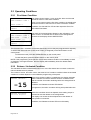
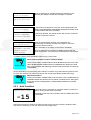
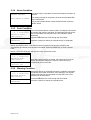
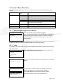
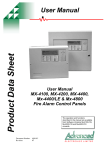
Product Data Sheet
Ex-3000 Series
Installation and User Manual for
Ex-3020 & Ex-3030
Remote Status Indicator Panels
The operation and functions
described in the manual are
available from Software Versions
Ex3030_V2_00 onwards.
Item
Specification Details
Ex-3020
Enclosure
Ex-3021
Ex-3030
Ex-3031
Steel IP30
Dimensions H x W x D mm
190 x 235 x 45
Environmental Class
Class A – Indoor IP30 0°C to 40°C
Humidity
95 % Max
Weight (excluding batteries)
1.5Kg
Cable Entries (20mm knockouts)
4x top and 4x bottom rear
Power Supply
24V DC Nominal (18V – 28V DC); 35mA max (backlight on1), 20mA max (backlight off1).
Relay Outputs (Optional)
2x rated at 1A 30VAC/DC (max) 10mA 5V (min) programmable (requires EXP-007)
Key-Switches 1x programmable
Optional
Fitted
Optional
Fitted
Manual Release
No
No
Yes
Yes
External Inputs (Monitored)
2x Programmable
Communications
RS485 to EX-3000 Series Control Panel
Display
Graphic LCD 124x64 dots
LED Indicators
12
As our policy is one of constant product improvement the right is therefore reserved to modify product specifications without prior notice
1
Backlight state is dictated by control panel – refer to control panel installation manual.
Page 2 of 18
Table of Contents
1
INTRODUCTION __________________________________________________________ 4
1.1
1.2
1.3
2
Standards ____________________________________________________________ 4
Cautions and Warnings__________________________________________________ 4
Description ___________________________________________________________ 4
OPERATION _____________________________________________________________ 5
2.1
Introduction ___________________________________________________________ 5
2.1.1
Front Panel Controls and Indications____________________________________ 5
2.1.1.1
2.1.1.2
2.1.1.3
2.1.1.4
2.1.1.5
2.1.1.6
Display ________________________________________________________________
LED Indications __________________________________________________________
Manual Release Button (Ex-3030 Only) _______________________________________
Navigation Buttons _______________________________________________________
Key-Switches ___________________________________________________________
Buzzer _________________________________________________________________
5
6
6
7
7
7
2.2
Operating Conditions ___________________________________________________ 8
2.2.1
Fire Alarm Condition ________________________________________________ 8
2.2.2
Release / Activated Condition _________________________________________ 8
2.2.3
Hold Condition _____________________________________________________ 9
2.2.4
Abort Condition ___________________________________________________ 10
2.2.5
Fault Condition____________________________________________________ 10
2.2.6
Warning Condition _________________________________________________ 10
2.3
Level 1 Menu Functions ________________________________________________ 11
2.3.1
Navigating through Level 1 Menus ____________________________________ 11
2.3.2
View ____________________________________________________________ 11
2.3.2.1
2.3.2.2
2.3.2.3
2.3.2.4
2.3.3
2.3.4
3
Faults ________________________________________________________________
Disables ______________________________________________________________
Warnings ______________________________________________________________
Software Versions _______________________________________________________
11
12
12
12
LED Test ________________________________________________________ 12
Exit_____________________________________________________________ 12
INSTALLATION__________________________________________________________ 13
3.1
Installation Approvals __________________________________________________
3.1.1
Fire System Installations ____________________________________________
3.1.2
Wiring Regulations_________________________________________________
3.2
Identification of Parts __________________________________________________
3.3
Installing the back box _________________________________________________
3.4
Wiring Installation _____________________________________________________
3.4.1.1
3.4.1.2
3.4.1.3
3.4.1.4
3.4.1.5
3.5
3.6
24V DC Power _________________________________________________________
Relay Outputs __________________________________________________________
RS485 Communications __________________________________________________
Input Circuits ___________________________________________________________
USB__________________________________________________________________
13
13
13
13
14
15
15
15
16
16
16
Key-Switch Installation _________________________________________________ 17
Adjusting the LCD Contrast / Address setting________________________________ 17
Page 3 of 18
1 Introduction
1.1
Standards
The Ex-3000 Series of Gas Extinguishing Remote Status Indicating Panels conform to the
following standards:
BS EN60950: 2000
Safety of information technology equipment
BS EN50130-4: 1996
Product Family Standard
Electromagnetic Compatibility Directive 89/336/EEC (and the amending directive 92/23/EEC)
Low Voltage Directive 73/23/EEC
1.2
Cautions and Warnings
Only Trained service personnel should undertake the Installation,
Programming and Maintenance of this equipment.
1.3
Description
This manual covers the installation and use of the Ex-3000 Series Remote Status Indicating
Panels.
The Ex-3020 is an RSI with Liquid Crystal Display and LED Indicators.
The Ex-3021 is an RSI with Liquid Crystal Display, LED Indicators and Mode Select Key Switch.
The Ex-3030 is an RSI with Liquid Crystal Display, LED Indicators and Manual Release Button.
The Ex-3031 is an RSI with Liquid Crystal Display, LED Indicators, Manual Release Button and
Mode Select Key Switch.
A Key-Switch can optionally be fitted to the Ex-3020 and Ex-3030.
Each RSI has built-in circuits for connection of two external input devices.
Each RSI has the option for two additional programmable relay outputs (requires additional
module).
All programming and configuration (except device address) is performed at the Ex-3001
Extinguishing Control Panel.
Page 4 of 18
2
Operation
2.1 Introduction
These instructions cover the operation and use of the panels.
2.1.1
Front Panel Controls and Indications
Ex-3030
LCD
Navigation Buttons
Manual Release
E X T IN G U I S H A N T
R E LE A S E
PULL DOWN AND PRESS BUTTON
FIRE
EXTINGUISHANT
RELEASE
IMMINENT
TIMER HELD
RELEASED
ZONE - 1
ABORTED
ZONE - 2
FAULT
ZONE - 3
DISABLED
Remote Status Indicator
MODE
MANUAL ONLY
CONTRAST
ADJUST
S UPP LY
AUTO +
MANUAL
INPUTS
SYSTEM FAULT
485 -IN
485-OU T
Extinguishant Status
USB
REBOOT
SWITCH
R UN PROG
General Status
Key-Switch
Ex-3020
The Ex-3020 has an identical arrangement to the Ex-3030 but is without the Manual Release
function.
2.1.1.1 Display
The LCD along with the LED Indicators shows the operating status of the system. Examples of
the information presented is shown below:
Normal Display
SYSTEM NORMAL
Non-normal Display
Menu Display
[System status]
1 of 1 conditions:
DETECTION ZONE3
OPEN CIRCUIT
[Level 1 Menu]
VIEW
LED TEST
EXIT
.
22 AUG 2007 16:39:00
[Release status]
UNAFFECTED
Release Imminent
Release Activated
Release Complete
[Release status]
RELEASE IMMINENT..
RELEASE ACTIVATED
00:00:05 Elapsed
RELEASE ACTIVATED
00:00:24 Elapsed
GAS RESET INHIBITED
DISCHARGE COMPLETE
(No Flow Detected)
RESET ALLOWED
-15
The display shows a countdown
timer with the amount of time
remaining before the extinguishant
is released.
The display shows the time
elapsed since the extinguishant
release commenced.
Page 5 of 18
2.1.1.2 LED Indications
The LED Status Indications show the basic operational state of the panel and whether the panel
is in a fire alarm, fault, disabled or test condition.
2.1.1.2.1
GENERAL STATUS
Function
Colour
Description
SYSTEM FAULT
Yellow
Indicates the presence of a system fault
2.1.1.2.2
DETECTION ZONE STATUS
Function
Colour
Description
Red
Indicates that the system has detected a fire alarm condition in the respecitve zone
FIRE
2.1.1.2.3
EXTINGUISHANT
Function
Colour
Description
RELEASE IMMINENT
Red
Indicates (flashing) that the release of extinguishant is imminent. The indication will turn to
steady when the signal to release the extinguishant has been activated.
RELEASED
Red
Indicates that the release of extinguishant has occurred and the panel has detected the folw
of the extinguishant released.
TIMER HELD
Yellow
Indicates that the imminent release of extinguishant is temproraily suspended.
ABORTED
Yellow
Indicates that the imminent release of the extinguishant has been aborted.
DISABLED
Yellow
Indicates that the extinguishant release control signal has been disabled. The release of
extinguishant is prevented even if a fire alarm or manual release are present.
FAULT
Yellow
Indicates that the system has detected a fault condition within part of the extinguishing
system and control device (ECD) circuits.
MANUAL ONLY
Yellow
Indicates that the extinguishant can only be released by means of a manual release button.
AUTO + MANUAL
Yellow
Indicates that the extinguishant can be released by both the automatic detection of a fire
alarm and by means of a manual release button.
2.1.1.3 Manual Release Button (Ex-3030 Only)
To manually release the extinguishant, pull down the flap and press the button marked with the
circle.
Page 6 of 18
2.1.1.4
Navigation Buttons
Press to scroll through the list of event conditions.
Press to scroll through menu options.
Press to display the menu and confirm selection of a menu
option.
Press to exit from a menu option.
Press to MUTE panel buzzer (if configured).
2.1.1.5
Key-Switches
One key-switch is fitted to the panel.
The functions of these are programmable and the installer
will have inserted a label to indicate their use.
Typical uses are:
AUTO + MANUAL / MANUAL ONLY Selection
EXTRACT OVERRIDE
Depending on the key-switch mechanism fitted, the key
may be removable in only one position or removable in
both operating positions.
2.1.1.6 Buzzer
The buzzer produces two different sounds to differentiate between fire alarm conditions and fault /
warning conditions.
Condition
Operation
Fire Alarm
The buzzer operates with a continuous tone.
Fault
The buzzer operates intermittently.
Page 7 of 18
2.2 Operating Conditions
2.2.1
Fire Alarm Condition
[Fire Detected]
FIRE STARTED: ZONE 1
The display shows location / origin of the fire alarm and the total
number of zones in a fire alarm condition.
TOTAL FIRES: 1
If two or more zones enter the fire alarm condition, the display also
shows the location of the last zone to enter a fire alarm condition.
[Release Status]
STAGE-1
In addition, the General Fire LED and the respective Zone Fire
LED will be illuminated.
[Fire Detected]
FIRE STARTED: ZONE 1
LAST FIRE
: ZONE 3
TOTAL FIRES : 2
The status of the extinguishant release is also indicated. If a fire
alarm occurs in a zone that has no effect on the extinguishant
control then the display shows UNAFFECTED.
[Release Status]
STAGE-1
The fire alarm bells / sounders will activate (depending on how they are programmed to respond).
To silence the internal buzzer, press the button (if configured) or the MUTE button on the
control panel.
To silence the bells, press the SILENCE button on the control panel.
To reset the panel, press the RESET button on the control panel.
NOTE: If the programming of the panel is such that the release condition is immediately invoked
on detection of a single fire alarm, then the display will immediately show the release status
information.
2.2.2
Release / Activated Condition
The activated condition is established when one or more fire alarms have occurred or when the
manual release button is pressed.
The number of zones, and which zones, that must be in a fire alarm condition before the activated
condition is invoked depends on the installation programming of the panel.
[Release status]
RELEASE IMMINENT..
-15
RELEASE ACTIVATED
00:00:05 Elapsed
When the activated condition is established, the display indicates
that the release is imminent and also shows a countdown timer
with the number of seconds remaining before the extinguishant is
released.
In addition, the Release Imminent LED flashes.
If programmed, the bells / sounders will ring with pulsed alert tone.
When the countdown timer has elapsed, the actuating output is
activated to start the release of the extinguishant.
The display now shows the time elapsed since the release of
extinguishant commenced.
In addition, the Release Imminent LED turns ON steady.
Page 8 of 18
RELEASE ACTIVATED
00:00:10 Elapsed
When the discharge is complete (either time elapsed or flow
detected) the display indicates the discharge is complete.
DISCHARGE COMPLETE
(No Flow Detected)
RELEASE ACTIVATED
00:00:10 Elapsed
RELEASE CONFIRMED
DISCHARGE COMPLETE
RELEASE ACTIVATED
00:00:20 Elapsed
DISCHARGE COMPLETE
EXTRACT RUNNING
RESET ALLOWED
If confirmed by the detection of the flow of the extinguishant, the
display shows RELEASE CONFIRMED (Released Condition) and
the RELEASED LED turns ON steady.
If previously silenced, the internal buzzer will re-sound. Press the
button to silence the buzzer.
When the extinguishant has been fully released and if
automatically or manually activated, the output to control the
extract fan will be turned on.
This is indicated on the display as EXTRACT RUNNING
When the discharge is complete, the display prompts that the
panel can be reset – reset must be performed at the control panel.
To reset the panel, press the RESET button on the control panel.
Reset of the Activated Condition / Release Signal.
Section 4.12.2
NOTE: In accordance with EN 12094-1, the ECD shall not permit a reset until
either the RELEASED condition has been established (flow detected) or until
after a programmable time following activation of the mechanism to release the
extinguishant.
NOTE: Depending on programming, the EXTRACT condition may persist after the panel is reset
for up to 120 minutes. This will be indicated on the normal status display (Extract Running).
Section 4.11
2.2.3
Released Condition.
NOTE: In accordance with EN 12094-1, the activated / release condition may be
established without the detection of a fire alarm or manual release. If the panel
detects the release of extinguishant, it will immediately indicate the released
condition.
Hold Condition
COUNTDOWN ON HOLD
(Remove HOLD resume)
If any hold button is activated, the imminent release countdown is
held for as long as the button is pressed.
-15
The display shows the HOLD condition and the TIMER HELD LED
is illuminated.
When the hold button is release, the panel will resume the imminent release countdown either
from the time remaining or from the maximum time programmed.
Page 9 of 18
2.2.4
Abort Condition
RELEASE ABORTED!
PRESS RESET TO REARM
If an abort button is activated, the imminent release countdown is
aborted.
The display prompts for the panel to be reset and the ABORTED
LED is illuminated.
Ensure that the abort button is de-activated and then press the
RESET button.
2.2.5
Fault Condition
[System status]
1 of 1 conditions:
DETECTION ZONE3
OPEN CIRCUIT
If the control panel detects a fault condition, the display will indicate
the number and nature of the faults. The internal buzzer will sound
with an intermittent tone and the FAULT LED indication will be
illuminated.
[Release status]
UNAFFECTED
Press the button to silence the internal buzzer (if configured).
Press the ÏÐ buttons to scroll through the list of faults.
NOTE: The fault condition is non-latching (except System Fault) and the indications will
automatically be cleared when the fault is remedied. Press the RESET key to clear a System
Fault.
NOTE: If silenced, the buzzer will re-sound when a new fault occurs.
[System status]
1 of 1 conditions:
DETECTION ZONE3
OPEN CIRCUIT
For service call:
01234 567 890
2.2.6
When the system buzzers are muted, the bottom two lines of the
display will show the telephone number to call for service (if
programmed) for four seconds.
Warning Condition
[System status]
1 of 1 conditions:
PRESSURE MONITOR
OPEN CIRCUIT
If the panel detects an extinguishant warning condition, the display
will indicate the number and nature of the warnings. The internal
buzzer will sound with an intermittent tone and the FAULT LED
indication will be illuminated.
[Release status]
UNAFFECTED
Press the button to silence the internal buzzer.
Page 10 of 18
Press the ÏÐ buttons to scroll through the list of faults.
2.3 Level 1 Menu Functions
The following table gives a list of the Level 1 Menu Functions and a brief description for each
function.
Menu Option
Sub Menu /
Item
Comments / Description
VIEW
FAULTS
View any current fault conditions recorded.
DISABLES
View any current disablement conditions.
WARNINGS
View any current extinguishant warnings conditions.
LOG
View the history log.
SW VERSIONS
View the software version installed in the extinguishant control panel
and in remote status indicator panels.
LED TEST
--
Disable Zone, Sounder, Input and Output circuits and disable
functions. Enable any current disablement conditions
EXIT
--
Return to the normal status display.
2.3.1
Navigating through Level 1 Menus
[Level 1 Menu]
VIEW
LED TEST
EXIT
Press the button to select the Menu Options
.
When the menu is displayed, use the ÏÐ buttons to highlight the
required menu option and then press the button to select it.
Press the button from within a menu option to return to the
previous menu.
The display will revert to the status mode display after 60 seconds on no activity (15 seconds in a
fire alarm condition). Press the button again to return to the menu option.
2.3.2
View
On selection, the current status of any Faults, Disablements and Warnings along with the history
Log can be shown.
[View Menu]
FAULTS
DISABLES
WARNINGS
SW VERSIONS
EXIT
.
If there are no conditions present, the display will show “Nothing to
Report”.
[Fault Status]
Nothing to Report
2.3.2.1 Faults
[Fault Status]
1 of 3
DETECTION ZONE 1
>SHORT CIRCUIT
DETECTION ZONE 2
>OPEN CIRCUIT
Press the ÏÐ buttons to scroll through the list and press the button to select the required view option.
.
.
If there are fault conditions present, the display will show the
number of conditions and a list of the fault conditions.
Press the ÏÐ buttons to scroll through the list of faults.
Press the button to return to the previous menu.
Page 11 of 18
2.3.2.2 Disables
[Disable List]
Zone 1
DISABLED
Man Release DISABLED
If there are disablement conditions present, the display will show
the number of conditions and a list of the disablements.
Press the ÏÐ buttons to scroll through the list of disablements.
Press the button to return to the previous menu.
Disable conditions can only be set on the control panel.
2.3.2.3 Warnings
[Warning Status]
1 of 2
VALVE MONITOR INPUT.
>VALVE CLOSED
.
PRESSURE MONITOR
>LOW PRESSURE
If there are warning conditions in the extinguishant system present,
the display will show the number of conditions and a list of the
warning conditions.
Press the ÏÐ buttons to scroll through the list of warnings.
Press the button to return to the previous menu.
2.3.2.4 Software Versions
The display shows the revision of software installed in this RSI. The software revisions of the
control panel and all RSI units can be viewed simultaneously on the panel.
[Software Versions]
RSI-6 : 02.00
On selection, the display shows a list containing the panel and any
configured remote status indicators along with the version of
software installed in each device.
Press the ÏÐ buttons to scroll through the list of entries.
Press the button to return to the previous menu.
2.3.3
LED Test
On selection, the front panel LED Indicators will be illuminated for a short period of time.
2.3.4
Exit
On selection, the display reverts to the normal status display indications.
Page 12 of 18
3 Installation
3.1
Installation Approvals
3.1.1
Fire System Installations
The panel must be installed and configured for operation in accordance with these instructions
and the applicable code of practice or national standard regulations for fire systems /
extinguishing system installation (for example BS5839-1: 2002, BS7273-1: 2006) appropriate to
the country and location of the installation.
3.1.2
Wiring Regulations
The panel and system must be installed in accordance with these instructions and the applicable
wiring codes and regulations (for example BS7671) appropriate to the country and location of the
installation.
3.2
Identification of Parts
The following diagram shows the major parts of the panel.
COVER
FIXING
SCREWS
F IRE
EXTING UISHA NT
RELEASE
IMMINENT
TIMER HELD
DISABLED
RELEASED
ZONE - 1
ABORTED
ZONE - 2
FAULT
ZONE - 3
Remote Status Indicator
M O DE
MANUAL ONLY
CONTRAST
ADJUST
S U P P LY
AUTO +
MANUAL
IN P U T S
SY STEM FAULT
4 85 -IN
4 8 5-OUT
USB
REBOOT
SWITCH
RUN PROG
The panel comprises a back box and cover, chassis assembly.
The chassis is mounted onto the back box via two screws and keyhole mounting holes. The
screws do not have to be removed to remove the chassis.
The chassis contains the main printed circuit card with terminal block connections for field wiring.
A fascia label is affixed to the front of the chassis providing the user controls and indications (LCD
and LED indicators). A hinged yellow plastic cover is fitted to the front face and provides access
to the manual release button (Ex-3030 only).
Standoff pillars are provided in the back box to fit a standard Exp-007 2-Way Relay Module. This
is connected to the main printed circuit card via ribbon cable.
Page 13 of 18
One (programmable function) key-switch assembly can be fitted to the chassis plate below the
manual release cover. The cables plug onto the main printed circuit card. Slide-in labels with preprinted text are available.
3.3
Installing the back box
Enclosure dimensions and fixing points are shown in the diagram below. Remove the chassis
before installing the enclosure (retain in a safe place).
Ensure that there is sufficient space to allow the cover to be removed / opened when the panel is
finally mounted.
235
Earth Studs
4x Tyrap cable
fixing anchors
25
94
Page 14 of 18
94
188
170
4x Mounting pillars
for Exp-007
3.4
Wiring Installation
The unit is designed for easy wiring installation.
“Plug-in” terminal blocks are provided for all
connections to the unit.
NB: Minimum / Maximum cable size for terminal
block connections is limited to 0.35mm² 2.5mm² (22-14AWG).
To maintain electrical integrity of the SELV wiring on the
DC Power and Communications lines all SELV wiring
should be segregated from LV mains wiring and be wired
using cable with insulation suitable for the application.
All electrical wiring installation work should be carried out in
accordance with the code of practice applicable in the
country of installation.
In areas where cabling may come into contact with high
frequency interference, such as portable radio transceivers
etc. the data wiring cable should be of a twisted pair
construction within a overall screen. Care should be taken
to correctly terminate this screen, refer to the information
below.
3.4.1.1 24V DC Power
A 24V DC power supply is required.
Note: The DC power supply used MUST BE
designated a Safety Extra Low Voltage (SELV)
supply.
Connect the 24V DC supply feed input to the
SUPPLY +24V and 0V terminals on the
interface card.
Use cables of sufficient size to ensure that the
power input voltage is maintained under all
supply conditions – refer to specifications
section.
Must be
earthed
To minimise the effects of EMC interference all data wiring
circuits should be wired with a twisted pair of conductors
with a cross sectional area suitable for the loading
conditions.
SUPPLY
CONTRAST
ADJUST
IN PUTS
OBSERVE POLARITY OF CONNECTIONS
A secure ground connection is required. Although no system is immune to the effects of
lightning strikes, a secure ground connection will reduce susceptibility.
Run an earth cable (or use the drain wire of the DC Power lead) between the unit and
the control panel. Fixing points are provided in the back of the enclosures to terminate
the earth.
3.4.1.2 Relay Outputs
If additional relays are required, then install the
Exp-007 2-Way Relay card in the rear of the
enclosure.
Mounting pillars are provided. Affix the card with
the supplied M3 fixing screws.
Connect the 4-Way ribbon cable between the
relay card and the main chassis card (PL3) –
the connectors are polarised to prevent incorrect
connection.
RELAY
1
COM NC
RELAY
2
NO COM NC
NO
Two changeover volt-free relay outputs are
provided. Each is rated at 30V AC/DC, 1A,
resistive.
Both Relay outputs are programmable (refer to
Extinguishing Control Panel manuals).
Page 15 of 18
3.4.1.3 RS485 Communications
One RS485 bus circuit is provided for connection
of the Remote Status Indicator panels to the
Extinguishing Control Panel.
485-IN
INPUTS
4 85 - O U T
REBO
SWITC
SUPERVISED. POWER LIMITED.
Wiring to be twisted pair. The use of screened
cable is recommended in noisy environments.
Maximum distance 1000m. Maximum line
impedance 50Ω.
SCR B A SCR B A
Connect the cable from 'A' to 'A' and from 'B' to 'B'.
Equipment is connected via a daisy chain. A 150Ω
End-of-Line resistor to be fitted at last unit.
Connect the screen to one of the earth studs in
the back of the panel enclosure and to the
designated point in the remote status indicator
panels. Ensure the screen is continuous.
Remote
Status
Indicator
OUT
SCR B A SCR B A
Remote
Status
Indicator
IN
OUT
150Ω
Extinguishing
Panel
A B
RS485
AUX Supply
3.4.1.4 Input Circuits
Two Programmable Function Input Circuits are
provided.
Each input circuit is monitored for open and short
circuit conditions – see typical arrangement below.
IN
INPUTS
485- IN
4 85-O UT
REBO
SWITC
EOL = 6800Ω. Maximum line impedance 50Ω.
Connect to volt-free switches / relay contacts only.
6K8
470R
TYPICAL SWITCH
ARRANGEMENT
VALVE MONITOR SWITCH
ARRANGEMENT
6K8
6K8
470R
VALVE FULLY OPEN
VALVE FULLY CLOSED
The VALVE MONITOR input is used to monitor the open / closed state of a mechanical valve control
device.
If the valve is in an indeterminate state (neither fully open nor fully closed) for more than 30 seconds, the
panel will indicate a fault condition.
The function / action of the inputs is defined in the control panel. Refer to the control panel manual for
further details. If unused, connect a 3300Ω (or 2x 6800Ω in parallel) EOL across the terminals.
3.4.1.5 USB
The USB socket is for connection to a Laptop or PC.
This can be used for upload of a new logo.
Page 16 of 18
485-IN
485-OU T
USB
REBOOT
SWITCH
RUN
3.5
Key-Switch Installation
RELEASED
TIMER HELD
DISABLED
PL1
F IR E
EX T IN G U ISH A NT
RELEASE
IMMINENT
Z O NE - 1
ABORTED
Z O NE - 2
FAULT
Z O NE - 3
PL3
Remote Status Indicator
SLIDE-IN LABEL
MO DE
MANUAL ONLY
CON TRAST
AD JU ST
S U P P LY
AUTO +
MANUAL
IN P UTS
SY STEM FAULT
4 8 5- IN
4 85 - O U T
PL2
USB
RE BOOT
SWITC H
R U N PROG
PL2: KEY-SW
Key-Switch Assembly
PL3: 2-Way Relay Card
PL1: Manual Trigger
Nut
Using a sharp knife, cut through the fascia label using the key-switch mounting hole as a
template.
Insert the key-switch assembly through the hole and secure with the fixing nut. Before fully
tightening, insert the slide-in label with the required function description into the pocket in the
fascia label.
Plug the connector into the respective connector on the card.
Key-Switch assemblies are available in both trapped and non-trapped versions.
The function / action of the key-switch is defined in the control panel. Refer to the control panel
manual for further details.
3.6 Adjusting the LCD Contrast / Address setting
Press the CONTRAST ADJUST button. This display will show the contrast adjust option.
Use the ÏÐ buttons to adjust the contrast (viewing angle) darker
or lighter as required. The bar graph adjusts to show the contrast
setting.
Press the button to confirm the setting.
The display will then show the unit address.
[RSI Address Setup]
THIS ADDRESS: 1
Use the ÏÐ buttons to adjust the address as required.
Press the button to confirm the setting.
The display will then revert to the normal operating display.
Page 17 of 18
This page is intentionally left blank.
Document Number:
680-149
Revision:
03
34 Moorland Way : Nelson Park : Cramlington
Northumberland : NE23 1WE
Tel: +44 (0)1670 707 111
Fax: +44 (0)1670 707 222
www.Advel.co.uk Email: [email protected]
Page 18 of 18