1
Product Data Sheet
Ex-3000 Series
Installation and Commissioning
of
Ex-3001
Extinguishing Control Panel
The operation and functions
described in the manual are available
from Software Versions
Ex3001_V1_02 onwards.
Item
Specification Details
Ex-3001
Enclosure
Steel IP30
Dimensions H x W x D mm
330 x 400 x 90
Environmental Class
Class A – Indoor IP30 0°C to 40°C
Humidity
95 % Max
Weight (excluding batteries)
5.1Kg
Cable Entries (20mm knockouts)
17x top and 13x top rear
Mains Supply
200V-240V (+10%, -15%), 50/60Hz AC, 1.0A max
Power Supply
24V DC, 3A High Efficiency Switched Mode [2A load, 1A battery charging]
Battery Capacity
24V 4Ah Internal (min), 24V 7Ah Internal (max)
Charging Current
1.0A Temperature Compensated (27.4V DC nominal at 20°C)
Number of Fire Zones
3
Number of Flooding Zones
1
Actuator Output
24V DC, 1.0A suitable for either Metron or Solenoid
Sounder Outputs
3x rated at 1A each programmable
Relay Outputs
4x rated at 1A 30VAC/DC (max) 10mA 5V (min) [2x Fixed – Fire / Fault, 2x Programmable]
Relay Outputs (Optional)
8x rated at 1A 30VAC/DC (max) 10mA 5V (min) programmable (requires MXP-008)
Key-Switches (Optional)
2x Programmable
External Inputs (Monitored)
7x Fixed (Mode, Manual Trigger, Hold, Abort, Flow Monitor, Valve Monitor, Pressure Monitor)
4x Programmable
AUX Supply Output
24V DC, 0.5A
Communications
RS485 to Remote Status Indicators
Display
Graphic LCD 124x64 dots
LED Indicators
26
Event log
100 Fire / Trigger Events, 500 General Log Events
Approvals (pending)
BS EN 12094-1: 2003, BS EN 54-2: 1998 +A1, BS EN 54-4: 1998 +A2
As our policy is one of constant product improvement the right is therefore reserved to modify product specifications without prior notice
Page 2 of 42
Table of Contents
1
INTRODUCTION __________________________________________________________ 5
1.1
Standards ____________________________________________________________
1.2
Cautions and Warnings__________________________________________________
1.3
Description ___________________________________________________________
1.4
EN54 Functions _______________________________________________________
1.5
EN54 Optional Features with Requirements__________________________________
1.6
EN12094-1 Optional Features with Requirements _____________________________
1.7
Installation Approvals ___________________________________________________
1.7.1
Fire System Installations _____________________________________________
1.7.2
Wiring Regulations__________________________________________________
2
5
5
5
6
6
7
8
8
8
INSTALLATION___________________________________________________________ 9
2.1
Identification of Parts ___________________________________________________ 9
2.2
Installing the back box _________________________________________________ 10
2.3
Wiring Installation _____________________________________________________ 11
2.3.1
AC Mains Wiring __________________________________________________ 11
2.3.1.1
2.3.2
2.3.3
2.3.4
2.3.4.1
2.3.4.2
2.3.4.3
2.3.4.4
2.3.4.5
2.3.4.6
2.3.4.7
2.3.4.8
2.3.4.9
3
Cable Gland ___________________________________________________________ 11
Battery Wiring ____________________________________________________ 11
24VDC Power Supply Wiring _________________________________________ 12
External Wiring ___________________________________________________ 12
Relay Outputs __________________________________________________________
RS485 Communications __________________________________________________
AUX DC Supply Output___________________________________________________
Detection Zone Inputs ____________________________________________________
Sounder / Monitored Output Circuits_________________________________________
Input Circuits ___________________________________________________________
Actuator Output Circuit ___________________________________________________
USB__________________________________________________________________
Recommended Cable Routing _____________________________________________
13
13
14
14
15
16
17
18
18
2.4
Key-Switch Installation _________________________________________________
2.5
Adjusting the LCD Contrast______________________________________________
2.6
Loading Calculations___________________________________________________
2.6.1
Panel Loading ____________________________________________________
2.6.2
Battery Standby Calculation__________________________________________
19
19
20
20
20
PROGRAMMING _________________________________________________________ 21
3.1
Introduction __________________________________________________________
3.1.1
Access Levels ____________________________________________________
3.1.2
Front Panel Controls and Indications___________________________________
3.1.3
Enable Controls ___________________________________________________
3.1.4
Navigating through menus ___________________________________________
3.1.5
Numeric data entry_________________________________________________
3.2
Recommended Programming Procedure ___________________________________
3.3
Level 3 Menu Functions ________________________________________________
3.3.1
Detection Zones___________________________________________________
3.3.2
Alarms __________________________________________________________
3.3.2.1
3.3.2.2
3.3.3
3.3.3.1
3.3.3.2
3.3.3.3
3.3.3.4
3.3.4
3.3.5
3.3.5.1
3.3.6
3.3.6.1
3.3.7
3.3.7.1
3.3.8
3.3.9
21
21
21
22
22
23
23
23
24
24
Sounder Configuration ___________________________________________________ 24
Pulse Pattern Configuration _______________________________________________ 25
Extinguishing _____________________________________________________ 26
Output Set-Up __________________________________________________________
Cause and Effects Programming ___________________________________________
Extract Set-Up__________________________________________________________
Release Signal Termination (Test Function)___________________________________
26
27
27
29
Inputs ___________________________________________________________ 29
Outputs _________________________________________________________ 29
Switched AUX Output ____________________________________________________ 30
Passwords _______________________________________________________ 31
Default Passwords ______________________________________________________ 31
General Options___________________________________________________ 31
Daylight Saving Options __________________________________________________ 32
Status Indicators __________________________________________________ 33
Enable PC LINK___________________________________________________ 33
Page 3 of 42
3.3.10
4
Exit _____________________________________________________________ 33
SERVICE AND MAINTENANCE _____________________________________________ 34
4.1
Maintenance Schedule _________________________________________________ 34
4.1.1
Daily Actions _____________________________________________________ 34
4.1.2
Monthly Actions ___________________________________________________ 34
4.1.3
Quarterly Actions __________________________________________________ 34
4.1.4
Annual Actions ____________________________________________________ 34
4.2
Replacement of Components ____________________________________________ 35
4.2.1
Batteries _________________________________________________________ 35
4.2.2
Liquid Crystal Display_______________________________________________ 35
5
APPENDICES ___________________________________________________________ 36
5.1
Appendix 1 – Forgotten Level 3 Password __________________________________ 36
5.2
Appendix 2 – Compatible Devices_________________________________________ 37
5.2.1
Detectors ________________________________________________________ 37
5.3
Appendix 3 – Recommended Cables ______________________________________ 39
5.3.1
Fire Rated Cables _________________________________________________ 39
5.3.2
Non-Fire rated cables_______________________________________________ 39
5.4
Appendix 4 – Troubleshooting____________________________________________ 40
Page 4 of 42
1 Introduction
1.1
Standards
The Ex-3000 Gas Extinguishing Control Panel conforms to the following standards:
BS EN12094-1: 2003
Extinguishing Control Device
BS EN54-2: 1998
Control and Indicating Equipment
BS EN54-4: 1998
Power Supply Equipment
BS EN60950: 2000
Safety of information technology equipment
BS EN50130-4: 1996
Product Family Standard
Electromagnetic Compatibility Directive 89/336/EEC (and the amending directive 92/23/EEC)
Low Voltage Directive 73/23/EEC
1.2
Cautions and Warnings
BEFORE INSTALLATION – Refer To the Ratings shown on the label inside
the product and to the ‘Specifications Chart’ in this document.
Please read this manual carefully. If you are unclear on any point DO NOT
proceed. Contact the manufacturer or supplier for clarification and guidance.
STOP
Only Trained service personnel should undertake the Installation,
Programming and Maintenance of this equipment.
This product has been designed to comply with the requirements of the Low
Voltage Safety and the EMC Directives. Failure to follow the installation
instructions may compromise its adherence to these standards.
ATTENTION
OBSERVE PRECAUTIONS
FOR HANDLING
ELECTROSTATIC
SENSITIVE DEVICES
1.3
This equipment is constructed with static sensitive components. Observe antistatic precautions at all times when handling printed circuit boards. Wear an
anti-static earth strap connected to panel enclosure earth point. Before installing
or removing any printed circuit boards remove all sources of power (mains and
battery).
Description
This manual covers the installation, programming and commissioning of the Ex-3000 Series
Extinguishing Control Panels. Refer to the User Manual (Document No. 680-148) for details of
how to operate the panel.
The Ex-3001 is a Single Flooding Zone Control Panel with up to three detection zone circuits.
The detection zones are compatible with conventional detectors and call points. Refer to the
compatibility section for full details of the compatible devices tested.
Install the panel, detection circuits, sounder circuits, etc. in accordance with the
instructions in Section 2 and then program the operation in accordance with the
instructions detailed in Section 3.
Page 5 of 42
1.4
EN54 Functions
This Control Panel is compliant with the requirements of EN54 parts 2 and 4 (1997).
In addition to the basic requirements, the following optional functions are provided
and these comply with the requirements of EN54.
CIE Optional Functions
Indication
Outputs
Controls
EN54-2 Clause
Outputs to Fire Alarm Devices
Co-incidence Detection
Alarm Counter
Test Condition
P.S.E Functions
7.8
7.12
7.13
10
EN54-4 Clause
Operation from a main power supply
Operation from a standby battery
Monitor and Charge the Standby Battery
Recognise and Notify Supply Faults
5.1
5.2
5.3
5.4
This Fire Alarm Control Panel also supports additional functions that are not covered
by EN54. These are as follows:
Additional Function
Refer to
Paragraphs
Auxiliary Power Supply Output
Auxiliary Relay Outputs
1.5
2.3.4.3
2.3.4.1
EN54 Optional Features with Requirements
In addition to the mandatory requirements of EN54 Part 2, the Control and Indicating Equipment
(CIE) supports the following optional features with requirements: Outputs to Fire Alarm Devices.
Section 7.8
The CIE has provision for connection to Fire Alarm Devices. It is possible to Silence
and Resound the alarms at Level 2. Refer to the User Manual for further information.
Refer to Sections 2.3.4.5 and 3.3.2 for information on installation and output
programming.
Alarm Counter.
Section 7.13
Page 6 of 42
The CIE has provision record the number of times that the fire alarm condition is
entered. Refer to the User Manual for further information.
Test Condition.
Section 10
1.6
The CIE has provision for testing the installation on a per zone basis. Refer to the
User Manual for further information.
EN12094-1 Optional Features with Requirements
In addition to the mandatory requirements of EN12094-1, the Extinguishing Control Device (ECD)
supports the following optional features with requirements: Delay of Extinguishing Signal.
Section 4.17
The ECD has provision to delay the transmission of the extinguishing signal. This can
be programmed in 1-second intervals up to a maximum of 60-seconds. Refer to
Section 3.3.3.1 for programming.
Monitor Flow of Extinguishing Agent.
Section 4.18
The ECD has provision to monitor the flow of the extinguishing agent once released.
One fixed input is provided. Programmable inputs can also be configured as hold
inputs. Refer to Sections 2.3.4.6, 3.3.4 and 3.3.3.1.
Monitor of Status of Extinguishing Components.
Section 4.19
The ECD has the provision to monitor the status of extinguishing components such as
loss of agent, temperature, etc. Refer to Sections 2.3.4.6, 3.3.4 and 3.3.3.1.
Means shall be provided to transmit the information concerning the blocked position
of a manual control device. Refer to sections 2.3.4.1 and 3.3.5 for further information.
Emergency Hold Device.
Section 4.20
The ECD has provision for an emergency hold device. Refer to Sections 2.3.4.6, 3.3.4
and 3.3.3.1.
Means shall be provided to transmit the information concerning the activation of an
emergency hold device. Refer to sections 2.3.4.1 and 3.3.5 for further information.
Control of Flooding Time.
Section 4.21
The ECD has provision to control the duration of the flooding time. Refer to Section
3.3.3.1 for programming.
Manual Only Mode.
Section 4.23
The ECD has provision to switch from Auto/Manual to Manual Only means of
establishing the extinguishing signal. This can be by Level 2 User Menu Option, fixed
input, programmable input or by Key-Switch Option. Refer to Sections 2.3.4.6, 3.3.4
and 3.3.3.1.
Page 7 of 42
Triggering Signals to Equipment within the System.
Section 4.24
The ECD has provision to transmit triggering signals to extinguishing system
equipment such as pilot cylinders, warning devices, etc. Refer to Sections 2.3.4.5 and
3.3.2.
These circuits are required to be monitored for fault conditions by the ECD.
Triggering Signals to Equipment outside the System.
Section 4.26
The ECD has provision to transmit triggering signals to other equipment such as
doors, ventilation shut down, etc. Refer to Sections 2.3.4.1 and 3.3.5.
These circuits are to be monitored for fault conditions by the receiving device.
Emergency Abort Device.
Section 4.27
The ECD has provision for an emergency abort device. This can be by fixed input or
programmable input Option. Refer to Sections 2.3.4.6, 3.3.4 and 3.3.3.1.
Means shall be provided to transmit the information concerning the activation of an
emergency abort device. Refer to sections 2.3.4.1 and 3.3.5 for further information.
Activation of Alarm Devices with Different Signals.
Section 4.30
1.7
1.7.1
The ECD has provision to activate sounding devices with different signals to indicate
the pre-discharge warning condition (pulsing, 1s/1s), the release condition
(continuous) and the hold condition (pulsing, 1s/4s). Refer to Sections 3.3.2.1 and
3.3.2.2.
Installation Approvals
Fire System Installations
The panel must be installed and configured for operation in accordance with these instructions
and the applicable code of practice or national standard regulations for fire systems /
extinguishing system installation (for example BS5839-1: 2002, BS7273-1: 2006) appropriate to
the country and location of the installation.
1.7.2
Wiring Regulations
The panel and system must be installed in accordance with these instructions and the applicable
wiring codes and regulations (for example BS7671) appropriate to the country and location of the
installation.
Page 8 of 42
2 Installation
2.1
Identification of Parts
The following diagram shows the major parts of the panel.
AC INPUT
RELAY MODULE
(OPTIONAL)
PSU MODULE
LIVE
EARTH
NEUTRAL
R ela y- 1
Rela y - 2
F IR E
R e la y
FA U LT
R e la y
R S 4 85
AUX
Su p p ly
Z O NE
-1-
ZONE
-2 -
ZO NE
- 3-
PSU
Comms
USB
SUPPLY
SND R
-1-
S N DR
-2 -
SNDR
-3-
MOD E Manual H O LD
S elect Trigger
A BO RT Pressure VA LVE FLOW Actuator PROG
Monitor M onitor Monitor O utput Input-1
PROG
Input-2
PROG
Input-3
PROG
Input-4
u P MOD E
RUN PROG
R EBO O T
DETECTION ZONES
-1-2-3FIRE
G E NE R A L
FIRE
SILENCED
FAULT
SOUNDER FAULT
DISABLE
TEST
POWER
SOUNDER DISABLED
SOUNDER DELAYED
SYSTEM FAULT
RELEASE
IMMINENT
RELEASED
ABC
DEF
GHI
JKL
MNO
DISABLED
FAULT
PQRS
TUV
WXYZ
MANUAL
DISABLED
LOW PRESSURE
M UTE
SILENCE/
RESOUND
S OUND
A LARM S
(HOLD 2s)
EXTINGUISHANT
RELEASE
PULL DOWN AND PRESS BUTTON
EXTINGUISHANT
R ES ET
!
FA ULT/
TES T/
DISA BLE
TIMER HELD
MANUAL ONLY
ESC
ABORTED
BS EN 54-2: 1998 BS EN 54-4: 1998
BS EN 12094-1: 2003
CLASS-A
SLIDE-IN LABEL
AUTO +
MANUAL
MENU
CHASSIS
ASSEMBLY
DOOR
BACK BOX
MANUAL RELEASE
COVER
The panel comprises a back box, door, chassis assembly and PSU module.
The chassis is mounted onto the back box via two screws and keyhole mounting holes. The
screws do not have to be removed to remove the chassis.
The chassis contains the main printed circuit card with terminal block connections for field wiring.
A fascia label is affixed to the front of the chassis providing the user controls and indications (LCD
and LED indicators). A hinged yellow plastic cover is fitted to the front face and provides access
to the manual release button.
The PSU module converts the in-coming AC Supply to 24V DC (nominal) and provides battery
charging. The PSU is connected to the chassis via a DC Cable and a serial communications
cable. The PSU design is to BS EN54-4: 1998 +A2 and provides monitoring for AC failure, battery
missing, battery low, charger failure and battery internal resistance.
Standoff pillars are provided in the back box to fit a standard Mxp-008 8-Way Relay Module. This
is connected to the main printed circuit card via ribbon cable.
Up to two (programmable function) key-switch assemblies can be fitted to the chassis plate below
the manual release cover. The cables plug onto the main printed circuit card. Slide-in labels with
pre-printed text are available.
Page 9 of 42
2.2 Installing the back box
90
Enclosure dimensions and fixing points are shown in the diagram below. Remove the chassis
before installing the enclosure (retain in a safe place).
LIVE
EARTH
330
26
275
NEUTRAL
160
160
400
When batteries are installed, the Ex-3000 can weigh in excess of 10Kg. Use appropriate fixing
hardware to secure the panel to the wall.
For example, drill the required holes in the supporting wall using a drill bit diameter 7.0 mm and
plug with a suitable 40mm long expansion plug. Affix the panel to the wall with M5 screws (length
40mm) or No.10 screws (length 1½”).
Ensure that there is sufficient space to allow the cover to be removed / opened when the panel is
finally mounted.
Page 10 of 42
2.3
2.3.1
Wiring Installation
AC Mains Wiring
The power supply is classified as Class1
equipment construction and must be earthed in
accordance to EN60950 recommendations.
Route the high voltage mains AC wiring into the
enclosure using a suitable knockout and keeping
the AC wiring away from any circuit boards and all
other wiring.
The panel must be connected to the
supply earth through the power
cable.
The mains input connector is shown
in the diagram opposite. Note the
Must be
earthed
positions of the earth, neutral and live
terminal connections.
These are clearly marked on the label next to the
connector. The connector block contains an
integral fuse holder for a 20mm fuse.
Secure the mains input wiring using a tie wrap as
close to the terminal block as possible.
The fuse is rated as follows:
T 3.15A H 250V
Replace with correct rating and specification only.
2.3.1.1
PSU Internal Mains
Wiring
Brown
Field Connections
FUSE
LIVE
Grn/Yel
EARTH
Blue
NEUTRAL
AC Mains terminations
Connect the EX-3000 to the mains supply
via a readily accessible, disconnect device
(Isolation Switch) and suitable earth fault
protection incorporated in the building
installation wiring.
The Mains cable should be a minimum cable
size of 0.75mm² rated at 250V and fused via
a 5A anti-surge fuse. Maximum cable size is
limited to 4mm².
Keep all mains wiring separate from the
Extra Low Voltage (ELV) battery cables and
power supply output cables.
Cable Gland
The cable gland and any cord clamp bushings used in routing the Mains cable through
the 20mm knockout must have a minimum flame-retardant rating of 94HB.
Suggested glands and bushings are: Type
Gland IP65 – Brass M20, EExd / Eexe
Gland IP68 – Nylon 66 M20 Black, UL94V2
Bushing – Nylon 66 M20 Black, UL94V2
2.3.2
Manufacturer
Lappcable
Multicomp
Multipcomp
Battery Wiring
The system is designed to charge 24V
batteries or two 12V batteries connected in
series. Refer to diagram opposite.
Use the short black connection link to
connect the batteries.
Use the Red & Black leads provided to
connect the batteries to the BAT+ & BAT–
terminals on the PSU module.
Mount the batteries on the bottom of the
enclosure.
+V DC POWER
0V DC POWER
BATTERY +
BATTERY –
OBSERVE POLARITY OF CONNECTIONS!
Page 11 of 42
2.3.3
24VDC Power Supply Wiring
The main printed circuit card on the chassis
is supplied with 24V DC from the power
supply.
In addition, the operating status of the power
supply is communicated to the main
electronics via a serial link.
The two cables are fitted as standard and
plug onto the main printed circuit card.
+V DC POWER
0V DC POWER
BATTERY +
BATTERY –
COMMS LEAD
DC POWER LEAD
Refer to diagrams opposite.
To remove the chassis assembly, disconnect
the two cable plugs from the chassis card
itself. There is no need to remove the wiring
from the power supply.
SERIAL COMMS
DC POWER
Note: If wired correctly, the DC Supply plug is
reversible without presenting a danger of
polarity reversal.
OBSERVE POLARITY OF CONNECTIONS!
2.3.4
External Wiring
Install cables suitable for the application and
degree of fire protection required.
All input and output circuits are SELV type.
To maintain electrical integrity of the SELV
wiring on the output lines all SELV wiring
should be segregated from the LV mains wiring
and be wired using cable with insulation
suitable for the application.
NB: Minimum / Maximum cable size for all
connections is limited to 0.35mm² / 2.5mm² (2214AWG).
Any specific recommendations are detailed
below for each type of circuit.
Refer to the Recommended Wiring Routing
section for details of cable routing within the
enclosure.
Page 12 of 42
ZONE
-2 -
ZO NE
-3-
PSU
Comms
SUPPLY
SND R
-1-
SNDR
-2-
SN
-
General Notes
All electrical wiring installation work should be
carried out in accordance with the code of
practice applicable in the country of installation.
To minimise the effects of EMC interference all
data wiring circuits should be wired with a
twisted pair of conductors with a cross sectional
area suitable for the loading conditions.
In areas where cabling may come into contact
with high frequency interference, such as
portable radio transceivers etc. the output
wiring cable should be of a twisted pair
construction within an overall screen. The
screen should be terminated to one of the
dedicated earth studs available in the panel.
2.3.4.1
Relay Outputs
Fault Output.
Section 8.8
The Fault Relay is arranged for failsafe operation as standard.
The panel is equipped with four relay outputs. See
diagram opposite for terminal block positions.
Each output is unsupervised with volt-free
changeover contacts rated at 30V AC/DC, 1A,
resistive.
The Fault and Fire Relays are fixed to indicate
their respective conditions.
Relay-1
The Fault relay is normally activated. It will deenergise on any fault condition including total loss
of power.
Relay-2
FA ULT
R ela y
F IR E
R e la y
R S485
Relay outputs 1&2 are programmable.
Additional Relays
If additional relays are required, then install the
Mxp-008 8-Way Relay card in the rear of the
enclosure.
RELAY
1
RELAY
2
RELAY
3
RELAY
4
RELAY
5
RELAY
6
RELAY
7
RELAY
8
Mounting pillars are provided. Affix the card with
the supplied M3 fixing screws.
Connect the 10-Way ribbon cable between the
relay card and the main chassis card – the
connectors are polarised to prevent incorrect
connection.
COM NC
NO COM NC
NO
COM NO COM NO COM NO
COM NO COM NO COM NO
Two changeover and six normally open volt-free
relay outputs are provided. Each is rated at 30V
AC/DC, 1A, resistive.
All Relay outputs are programmable.
2.3.4.2 RS485 Communications
One RS485 bus circuit is provided for connection
of local peripheral devices such as Remote Status
Indicator panels.
SUPERVISED. POWER LIMITED.
CCITT RS485 – Style 4
Wiring to be twisted pair and screened.
Maximum distance 1000m. Maximum line
impedance 50Ω.
FA ULT
Relay
R S485
Connect the cable from 'A' to 'A' and from 'B' to 'B'.
Equipment is connected via a daisy chain. A 150Ω
End-of-Line resistor to be fitted at last unit.
AUX
Su p p l y
ZO NE
-1-
SCR B A SCR B A
Remote
Status
Indicator
Connect the screen to one of the earth studs in
the back of the panel enclosure and to the
designated point in the remote status indicator
panels. Ensure the screen is continuous.
IN
OUT
ZONE
-2 -
ZO NE
-3-
SCR B A SCR B A
Remote
Status
Indicator
IN
OUT
150Ω
Extinguishing
Panel
A B
RS485
AUX Supply
Page 13 of 42
2.3.4.3 AUX DC Supply Output
Two Auxiliary Power Outputs are provided.
18.0 – 28.0 V DC, 0.5A1
SUPERVISED. POWER LIMITED.
AUX #1 : 4-Wire Smoke Detector Power or other
similar application. Power turns off for
10-15 seconds on reset.
AUX #2 : 24V DC (nominal) power output for
external equipment (remote status
indicators)2.
AUX-2 AUX-1
FA ULT
Relay
R S485
AUX
Supply
ZO NE
-1-
ZONE
-2 -
ZO NE
-3-
ZONE
-2 -
ZO NE
-3-
Use appropriately sized cable for the current load
to ensure device compatibility.
2.3.4.4
Detection Zone Inputs
In accordance with EN54-2, a maximum of 32 detectors per zone only.
Section 12.5.2
Three conventional detection zone inputs are
provided. These are nominally 20V DC circuits
and are current limited.
The circuits are monitored for open and short
circuits. For normal monitoring, a 6800Ω End-ofLine resistor is required.
The circuit is designed to be compliant with
conventional detectors and call points with an
equivalent series resistance of 470Ω/270Ω
respectively.
FA ULT
Relay
R S485
AUX
Sup ply
ZO NE
-1-
If using devices that apply a short across the zone
circuit, refer to Section 3.3.1 for how to configure
this use.
Detector
Detector
Call Point
Detector
Detector
Call Point
6800Ω
2.3.4.4.1 Standard Arrangement
Connect the detectors and manual call points (if
required) in series with no spurs.
Connect the en-of-line resistor across the
terminals of the last device.
Observe polarity of connections!
Zone-1 Zone-2 Zone-3
An Active-End-of-Line device is required instead
of the 6800Ω resistor.
1
AEL
2.3.4.4.2 Diode Base Arrangement
If the installation requires conformance to
BS5839-1: 2002 Code of Practice regarding the
supervision of removal of detectors and / or
operation of call points when detectors are
removed, then install the detectors using diode
bases.
Zone-1 Zone-2 Zone-3
TOTAL OUTPUT LOAD must not exceed panel supply rating – maximum 2A.
AUX-2 also provides power for the Mxp-008 8-Way Relay card. This current must be subtracted from the total available
AUX-2 power to give the available output power.
Page 14 of 42
2
HAZARDOUS AREA
IS Detector
Isolation
Barrier
11 +
1
12 –
2
The recommended isolation barrier is a
PEPPERL+FUCHS Model: KFDO-CS-Ex1.51P or
MTL Model: 5061
Only use intrinsic safe detectors and call points.
The number of devices permitted and cables will
depend on the IS classification – refer to the
detector manufacturers’ information for further
details.
IS Detector
IS Call Point
6800Ω
2.3.4.4.3 Intrinsic Safe Arrangement
The Zone Circuit can be configured for use with
Intrinsic Safety detectors and barriers – see
programming section.
SAFE AREA
Zone-1 Zone-2 Zone-3
The End-of-line resistor used must be rated for the
appropriate IS zone classification.
2.3.4.5 Sounder / Monitored Output Circuits
Three conventional 24V DC sounder style output
circuits are provided.
18.0 – 28.0 V DC, 1.0A3 max
SUPERVISED. POWER LIMITED.
The sounder outputs can be configured to turn
on continuously or to pulse (1s ON / 1s OFF).
The sounder outputs are monitored for open and
short circuit conditions using reverse polarity
signals.
SN D R
-1-
SUPPLY
S N DR
-2-
SND R
-3-
M O D E M an ua l H O LD
S e le c t Trig ge r
The outputs can be configured to be nonsilencing for use with pilot valves, etc. (refer to
section 3.3.2 for programming).
Sounder must be equipped with an in-built
blocking diode that prevents the sounder from
taking power when the output is in the
supervising condition.
EOL
10k ohm
EOL
10k ohm
An End-of-Line Resistor (EOLR) of value
10,000Ω ½ Watt must be fitted to the last
sounder / bell.
Ensure that cable of appropriate conductor size
is used to maintain the required sounder
operating voltage under the minimum battery
voltage condition – see below for calculation.
2.3.4.5.1 Intrinsic Safe Arrangement
The Sounder Circuit can be configured for use
with Intrinsic Safety sounders and barriers.
EOL
10k ohm
SDR-1 SRD-2 SDR-3
Isolation
Barrier
IS Sounders - Polarised
+
+
–
–
The recommended isolation barrier is a MTL
Model: 778ac
Only use intrinsic safe detectors and call points.
The number of devices permitted and cables will
depend on the IS classification – refer to the
sounder manufacturers’ information for further
details.
3
EOL
10k ohm
HAZARDOUS AREA
SAFE AREA
SDR-1 SRD-2 SDR-3
TOTAL OUTPUT LOAD (continuous) must not exceed panel supply rating – maximum 2A.
Page 15 of 42
2.3.4.5.2 Sounder Circuit Lengths
The voltage drop on each alarm circuit should be calculated to ensure that the minimum voltage
at the end of the circuit exceeds the minimum required by each sounding device at the minimum
alarm circuit output voltage.
The voltage at the end of the circuit is given by:
Minimum Alarm Voltage = VOUT(MIN) – (IALARM x RCABLE)
Minimum Output Voltage (VOUT(MIN)) is VBAT(MIN) – 1.0V = 20.0V
Alarm Current (IALARM) is the sum of the loads presented by the sounding devices in
alarm.
Cable Resistance (RCABLE) is the sum of the cable resistance in both cores x cable length.
Cable Resistance (RCABLE) for 1.0mm2 is 0.036Ω / metre
Cable Resistance (RCABLE) for 1.5mm2 is 0.024Ω / metre
Cable Resistance (RCABLE) for 2.5mm2 is 0.015Ω / metre
Insulation Resistance
(Core-Core and CoreScreen)
]2M Ω
2.3.4.6 Input Circuits
Seven Fixed function Input circuits are provided for
the following functions:
MODE SELECT [Auto / Manual], MANUAL
TRIGGER, HOLD, ABORT, PRESSURE MONITOR,
VALVE MONITOR and FLOW MONITOR.
Four Programmable Function Input Circuits are
provided.
Each input circuit is monitored for open and short
circuit conditions – see typical arrangement below.
R
-
MOD E Manual HO LD
Select Trigger
ABO R T P r essu r e VA LV E FLOW Actu
M on it or M o n it o r Monitor O ut
EOL = 6800Ω. Maximum line impedance 50Ω.
Connect to volt-free switches / relay contacts only.
6K8
470R
TYPICAL SWITCH
ARRANGEMENT
USB
LOW Actuator PROG
onitor O utput Input-1
6K8
6K8
470R
VALVE MONITOR SWITCH
ARRANGEMENT
VALVE FULLY OPEN
VALVE FULLY CLOSED
PROG
Input-2
PROG
Input-3
PROG
Inpu t- 4
uP MOD
RUN PR
The VALVE MONITOR input is used to monitor
the open / closed state of a mechanical valve
control device.
If the valve is in an indeterminate state (neither
fully open nor fully closed) for more than 30
seconds, the panel will indicate a fault
condition.
If unused, connect a 3300Ω (or 2x 6800Ω in
parallel) EOL across the terminals.
Page 16 of 42
2.3.4.7 Actuator Output Circuit
The actuator output can be used to drive both
igniting (metron) style and solenoid style
actuators.
18.0 – 28.0 V DC, 1.0A4
SUPERVISED. POWER LIMITED.
The circuit is monitored for both open and short
circuit conditions.
The output can supply a continuous 1A current for
solenoid style actuators or can provide a 3A
(15mS) pulse for igniting style actuators.
HO LD
ABO RT Pressure VA LV E F L O W A c tu a t or PROG
Monitor Mo n it o r M o n it o r O u t p u t Input-1
PROG
Input-2
Output type is configurable - refer to Programming
section.
2.3.4.7.1 Igniting Actuators
The circuit is current limited and one to four
igniting actuators can be wired in series without
special requirements.
M
M
M
M
Up to 4 igniting
actuators in series
No additional resistance is required in the circuit
Maximum line impedance 7Ω including the internal
resistance of the actuators.
2.3.4.7.2 Solenoid Actuators
A Back-EMF diode must be fitted across the
solenoid coil. Observe polarity – see diagram
opposite.
SOLENOID
MIN 30Ω
DIODE 1N4004 or
equivalent
Coil resistance 25Ω-200Ω.
Maximum line impedance 1.5Ω -5.0Ω depending
on coil impedance – see calculation below.
2.3.4.7.3 Solenoid Actuator Circuit Lengths
The voltage drop on the actuator circuit should be calculated to ensure that the minimum voltage
at the end of the circuit exceeds the minimum required by the solenoid (typically 18V) at the
minimum actuator circuit output voltage.
The voltage at the end of the circuit is given by:
Minimum Actuator Voltage = VOUT(MIN) – (IACTUATOR x RCABLE)
Minimum Output Voltage (VOUT(MIN)) is VBAT(MIN) – 1.5V = 19.5V
Actuator Current (IACTUATOR) is the sum of the loads presented by the actuator devices.
Cable Resistance (RCABLE) is the sum of the cable resistance in both cores x cable length.
Cable Resistance (RCABLE) for 1.0mm2 is 0.036Ω / metre
Cable Resistance (RCABLE) for 1.5mm2 is 0.024Ω / metre
Cable Resistance (RCABLE) for 2.5mm2 is 0.015Ω / metre
Insulation Resistance
(Core-Core and CoreScreen)
4
]2M Ω
TOTAL OUTPUT LOAD (continuous) must not exceed panel supply rating – maximum 2A.
Page 17 of 42
2.3.4.8 USB
The USB socket is for connection to a Laptop or
PC.
This can be used for upload of a new logo or
download of the configuration and log files.
Refer to section 3.3.9 for further information.
USB
FLOW Actuator PROG
r Monitor O utput Input-1
PROG
Input-2
PROG
Input-3
RU
PROG
Inpu t-4
2.3.4.9 Recommended Cable Routing
The following diagram shows the recommended cable routing within the enclosure.
Zone Inputs
Actuator
Output
AC IN
Sounder Outputs
485 / AUX
Relays
Inputs
AC INPUT
Cable Tie
LIVE
EARTH
NEUTRAL
R e la y- 1
R ela y - 2
FIR E
R e lay
FA U LT
R ela y
R S485
AUX
Sup ply
ZO NE
-1-
Z ON E
-2 -
Z ON E
-3-
PSU
Comms
USB
SUPPLY
SNDR
-1-
S NDR
-2-
SND R
-3-
MOD E Manual HO LD
S elect Trigger
A BO RT Pressure VA LVE FLOW Actuator PROG
Monitor Monitor Monitor O utput I np ut -1
PROG
In p ut-2
P ROG
Inp ut- 3
PROG
In pu t- 4
DETECTION ZONES
-1-2-3FIR E
G E N E R AL
FIRE
SILENCED
FAULT
SOUNDER FAULT
DISABLE
TEST
POWER
Page 18 of 42
SOUNDER DISABLED
SOUNDER DELAYED
SYSTEM FAULT
RELEASE
IMMINENT
ABC
DEF
GHI
JKL
MNO
PQRS
TUV
WXYZ
M U TE
SILENCE/
RESOUND
S OU ND
A LAR M S
(HOLD 2s)
E X T IN G U IS H A N T
R ELE AS E
PULL DOWN AND PRESS BUTTON
EXTINGUISHANT
R ES ET
!
FA ULT /
T ES T/
DISA BL E
TIMER HELD
MENU
ABORTED
DISABLED
FAULT
MANUAL
DISABLED
LOW PRESSURE
MANUAL ONLY
ESC
RELEASED
AUTO +
MANUAL
BS EN 54-2: 1998 BS EN 54-4: 1998
BS EN 12094-1: 2003
CLASS-A
u P MO D E
RUN PROG
R E BO O T
uP
2.4 Key-Switch Installation
R e la y - 1
R e l a y -2
F IR E
R e la y
FA U LT
R e la y
R S 485
AUX
S up ply
ZO NE
-1-
ZONE
-2 -
ZO NE
- 3-
PSU
Comms
USB
SUPPLY
SN DR
-1-
S N DR
-2-
SN DR
-3-
MOD E M an ua l H O LD
Select Trigge r
ABO RT Pressure VALVE FLOW Actuator PROG
Monitor Monitor Monitor O utpu t Input-1
PROG
Input-2
PROG
Input-3
PROG
Input-4
uP MODE
RUN PROG
REBOOT
DETECTION ZONES
-1-2-3F IR E
G E NE R A L
F IRE
FAULT
DISABLE
TEST
POWER
SOUNDER FAULT
SOUNDER DISABLED
SOUNDER DELAYED
SYSTEM FAULT
!
RELEASE
IMMINENT
PL3
DEF
GHI
JKL
MNO
DISABLED
FAULT
WXYZ
MANUAL
DISABLED
LOW PRESSURE
S IL E N C E /
RE SO U N D
PQRS
TUV
TIMER HELD
MANUAL ONLY
ESC
PL4
RELEASED
ABC
M U TE
SOUND
A LAR M S
(HOLD 2s)
EXTINGUISHANT
RELEASE
PULL DOWN AND PRESS BUTTON
EXTINGUISHANT
R ES ET
SILENCED
FA ULT/
TEST/
DISA BL E
ABORTED
BS EN 54-2: 1998 BS EN 54-4: 1998
BS EN 12094-1: 2003
CLASS-A
SLIDE-IN LABEL
PL4: KEY-SW #1
PL3: KEY-SW #2
AUTO +
MANUAL
MENU
Key-Switch Assembly
Nut
Using a sharp knife, cut through the fascia label using the key-switch mounting hole as a
template.
Insert the key-switch assembly through the hole and secure with the fixing nut. Before fully
tightening, insert the slide-in label with the required function description into the pocket in the
fascia label.
Plug the connector into the respective connector on the card.
Key-Switch assemblies are available in both trapped and non-trapped versions.
Refer to the Programming section to define the action of the key-switch.
2.5
Adjusting the LCD Contrast
Press the CONTRAST ADJUST button. This display will show the contrast adjust option.
Use the ÏÐ buttons to adjust the contrast (viewing angle) darker
or lighter as required. The bar graph adjusts to show the contrast
setting.
Press the button to confirm the setting.
The display will then revert to the normal operating display.
Page 19 of 42
2.6 Loading Calculations
2.6.1
Panel Loading
The Total Panel Load must not exceed the rating of the power supply. The power supply can
deliver a 2A total load maximum.
The panel loading includes the panel itself (70/125mA), any power required for additional option
modules and all external power required for the Input, Output and AUX circuits.
The backlight is turned off during AC supply failure (after 60 seconds). It turns on in Alarm or if the
panel keys are pressed.
2.6.2
Battery Standby Calculation
Quiescent Load
Equipment
I (A)
0.070
EX-3000 Panel
Mxp-008
0.000
5
x
1.0
Fire Alarm Load
Total
I (A)
= 0.070
x
Total
0.125
6
1.0
= 0.125
0.065
7
1.0
=
1.0
=
AUX #1 Supply Output8
1.0
=
1.0
=
8
1.0
=
AUX #2 Supply Output
1.0
=
9
Sounder Output 1
1.0
=
Sounder Output 29
1.0
=
9
1.0
=
1.0
=
Sounder Output 3
Actuator Output
Total
ΣQuiescent Load
ΣAlarm Load
=
x 24 hr =
Ahr
x 72 hr =
Ahr
=
210 x 0.5 hr =
(carry forward)
+
Ahr
Total Load (Quiescent + Alarm) =
Ahr
10
x 1.25 (Battery De-rating factor) =
5
Figure quoted is for mains fail condition (backlight off) – add 15mA for first hour of fault when the backlight is on.
Figure quoted is for fire in mains fail condition – with Relay1, Relay 2 & Fire relay energised (backlight on).
Figure quoted is for all relays on. 8mA per relay output on.
8
Maximum 0.5A load per AUX. Calculate the required load for each auxiliary output in both the quiescent and alarm
conditions. Refer to the technical information for each device that is to be powered from the panel AUX Output to
determine the overall AUX loading currents. The sum of all these additional currents should be entered in these fields.
9
Maximum 1.0A load per Sounder.
10
The alarm load should be doubled to allow for changes in battery efficiency for loads in excess of the recommended
C/20 discharge rate. The total load calculated should be multiplied by a de-rating factor of 1.25 to allow for changes in
battery efficiency over time. The above calculation is in accordance with the recommendations in BS5839-1: 2002.
Page 20 of 42
6
7
Ahr
Ahr
3 Programming
3.1
Introduction
These instructions cover the configuration and programming of the panels.
NOTE: The panel is delivered in a non-configured condition. In this mode (or if the panel is
returned to factory default settings) the panel defaults to MANUAL ONLY mode of operation.
After configuring the panel, use the Level 2 EXTINGUISH MODES menu option (or the
configured key-switch / inputs) to set the panel into the AUTO+MANUAL mode.
3.1.1
Access Levels
The panel operation is protected from inadvertent and erroneous misuse by means of four access
levels. These levels are as follows:
Level 1 Untrained user
Level 2 Authorised User
Level 3 Commissioning, Service and Maintenance
Level 4 Commissioning, Service and Maintenance – Special Tools Required
This document covers the Level 3 functions. For details on the operation and use of the panel at
Levels 1 & 2, refer to User Manual 680-148. Full details are supplied with any special tools.
A level-3 password is required to enter the commissioning menus. For details of Passwords, refer
to Section 3.3.6.
Level-3 Passwords.
If this number is lost, it is not possible to enter commission mode functions.
Refer to 5.1 for further information.
3.1.2
Front Panel Controls and Indications
LCD
R e la y - 1
R e la y -2
FIR E
R e la y
FA U LT
R e la y
R S 48 5
AUX
Sup pl y
ZONE
-1-
ZONE
-2 -
ZO NE
- 3-
Navigation Buttons
PSU
Comms
Manual Release Button
Detection Zone Status
USB
SUPPLY
SN DR
-1-
S ND R
-2 -
SND R
-3-
M OD E M an ual H O LD
S elect Trig ger
ABO RT Pressure VA LVE FL OW Actuator PROG
Monitor M onitor M o nitor O utput Input-1
PROG
Input-2
PROG
Input-3
PROG
Input-4
u P MO D E
RUN PROG
REBOO T
DETECTION ZONES
-1-2-3FIR E
G E NE R A L
F IRE
SILENCED
FAULT
SOUNDER FAULT
DISABLE
TEST
POWER
SOUNDER DISABLED
SOUNDER DELAYED
SYSTEM FAULT
RELEASE
IMMINENT
ABC
DEF
M U TE
TIMER HELD
RELEASED
ABORTED
GHI
JKL
MNO
DISABLED
FAULT
PQRS
TUV
WXYZ
MANUAL
DISABLED
LOW PRESSURE
S IL E N C E /
RE SOU N D
S O U ND
A LAR M S
(HOLD 2s)
EXTINGUISHANT
RELEASE
PULL DOWN AND PRESS BUTTON
EXTINGUISHANT
RESET
!
FA ULT /
TES T/
DISA BLE
MANUAL ONLY
ESC
BS EN 54-2: 1998 BS EN 54-4: 1998
BS EN 12094-1: 2003
CLASS-A
AUTO +
MANUAL
MENU
General Fire Status Control Buttons
Number Buttons
Extinguishant Status
Key-Switch Assembly
The LCD along with the LED Indicators shows the operating status of the system. Examples of
the information presented is shown below:
Page 21 of 42
Normal Display
Non-normal Display
Typical Menu Display
[System status]
1 of 1 conditions:
DETECTION ZONE3
OPEN CIRCUIT
22 AUG 2007 16:39:00
[Release status]
UNAFFECTED
[Level 2 Menu]
VIEW
TEST
EXTINGUISH MODES
DISABLE/ENABLE
EXIT LEVEL 2
Release Imminent
Release Activated
Release Complete
[Release status]
RELEASE IMMINENT..
RELEASE ACTIVATED
5 Seconds Elapsed
RELEASE ACTIVATED
24 Seconds Elapsed
SYSTEM NORMAL
-15
.
DISCHARGE COMPLETE
(No Flow Detected)
RESET ALLOWED
The display shows a countdown
timer with the amount of time
remaining before the extinguishant
is released.
3.1.3
Enable Controls
Controls are normally disabled. To access the menus, press the Menu button. The display shows
the following:
Enter Your Password
Enter Your Password
**
Press the button to select the
‘Enable Controls’ option.
The display prompts for entry of
the password.
Enter the password. As each
number is pressed, an * character
is displayed. Finally, press the button to confirm.
[Level 2 Menu]
VIEW
TEST
EXTINGHUISH MODES
DISABLE/ENABLE
EXIT LEVEL 2
Enter Your Password
Not Recognized!
[Level 2 Menu]
EXTINGHUISH MODES
DISABLE/ENABLE
EXIT LEVEL 2
DATE/ TIME
COMMISSION
[CONTROLS DISABLED]
ENABLE CONTROLS
VIEW
LED TEST
.
The display then shows the Level 2
Menu options.
3.1.4
If the password is incorrect (or if
not entered in time) the above
message is shown.
.
Scroll down to the Commission
Menu
Navigating through menus
When a menu is displayed, use the ÏÐ buttons to highlight the required menu option and then
press the button to select it.
Press the ‘Esc’ button from within a menu option to return to the previous menu.
Page 22 of 42
The display will revert to the status mode display after 60 seconds on no activity (15 seconds in a
fire alarm condition). Press the Menu button again to return to the menu option. A programmable
timer can be configured to automatically cancel Level 2 access.
3.1.5
Numeric data entry
Numbers are entered by moving to the required field, and then typing in the required number,
followed by the button. The display returns to the previous menu.
If the number is entered incorrectly, press the Í button to clear the entry and then re-enter the
required number. Alternatively, press the ‘Esc’ button to cancel the number entry and return to
the previous menu.
3.2 Recommended Programming Procedure
It is recommended that the configurable options be programmed in the following sequence:
• Configure General Options and Passwords
• Configure the Extinguishing Output Type and Cause & Effect Rule
• Configure the Detection Zone Input Circuits
• Configure the Alarm Outputs and Cause & Effect Rule
• Configure any other Input / Output Circuits
3.3 Level 3 Menu Functions
The following table gives a list of the Level 3 Menu Functions and a brief description for each
function.
Menu Option
Sub Menu
Comments / Description
3
ZONE 1
Configuration of the Detection Zone Input Circuits
DETECTION
ZONE 2
ZONE 3
4
ALARM OUTPUTS
SOUNDER 1
SOUNDER 2
Configuration of the Alarm Sounder Output Circuits and
pulsing operation
SOUNDER 3
PULSE PATTERN
2
EXTINGUISHING
OUTPUT SET-UP
Configuration of the Actuator Output Circuit
CAUSE & EFFECT
Configuration of the release cause and effects rule
EXTRACT SET-UP
Configuration of the Extract Output
5
INPUTS
Configuration of the Programmable Input Circuits
5
OUTPUTS
Configuration of the Programmable Output (Relay) Circuits
1
PASSWORDS
Configuration of the Engineer and User Passwords
1
GENERAL
Configuration of General parameters
5
STATUS INDICATORS
Configuration of any Remote Status Indicator Panels
ENABLE P.C. LINK
Permits the connection of a PC for upload of a logo or
download of the configuration and log files.
EXIT
Leave the Commission Menu
To enter the Commissioning / Programming Menu, select the COMMISSION option in the Level 2
Menu and press the button. The display prompts for the Level 3 password.
To exit from the Commissioning / Programming Menu, select the EXIT option and press the button. The display prompts for the Level 3 password.
Page 23 of 42
3.3.1
Detection Zones
This menu configures each of the three detection zone input circuits. Highlight the DETECTION
option and press the button. The following Zone Select Menu will be shown.
[Zone Select]
Zone 1
Zone 2
Zone 3
.
Use the ÏÐ buttons to highlight the required zone and
then press the button to select it.
A menu of parameters is then presented for the selected
zone.
[Zone 1 Settings]
SNDR DELAY :
0
VERIFY TIME : 0
I.S. ZONE
: NO
SHORT=ALARM : NO
NON-LATCH
: NO
.
Use the ÏÐ buttons to highlight the required parameter
and then press the button to select / change it.
The table below details the parameters can be adjusted:
Parameter
Comments / Description
Options
Default
Setting
SNDR DELAY
Determines if the sounders are to be delayed before operating
when the panel detects a fire alarm from this zone.
0 – 600 seconds
0
VERIFY TIME
Determines the minimum time that the circuit must be in the
alarm condition before an alarm condition is registered.
0 – 30 Seconds
0
I.S. ZONE?
Determines whether the circuit is for use with Intrinsic Safety
Barriers.
NO / YES
NO
SHORT=ALARM?
Determines if a short circuit is to be treated as an alarm
condition. If selected, the short circuit supervision on this circuit
is disabled. Normally, AFD or MCP devices will switch the circuit
into the alarm state via a 270Ω-470Ω resistor / equivalent load.
NO / YES
NO
NON-LATCH?
Determines if the panel should automatically reset from the
alarm condition if the alarm is cleared.
NO / YES
NO
3.3.2
Alarms
This menu configures each of the three alarm output circuits. Highlight the ALARM OUTPUTS
option and press the button. The following Sounder Select Menu will be shown.
[Sounder Select]
Sounder-1
Sounder-2
Sounder-3
PULSE PATTERN
.
3.3.2.1 Sounder Configuration
[Zone 1 Settings]
ZONE1 FIRE: ON
.
ZONE2 FIRE: ON
ZONE3 FIRE: ON
STAGE-1
: ON
COUNTDOWN : ON
Page 24 of 42
Use the ÏÐ buttons to highlight the required sounder (or
the pulse pattern option) and then press the button to
select it.
A menu of parameters is presented for the selected
sounder.
Use the ÏÐ buttons to highlight the required parameter
and then press the button to select / change it.
The table below details the parameters can be adjusted:
Parameter
Comments / Description
Options
Default Setting
SNDR1
SNDR2
SNDR3
ZONE 1 FIRE
Determines the response of the output to a fire
alarm condition from this zone.
OFF, PULSED, ON
ON
ON
OFF
ZONE 2 FIRE
Determines the response of the output to a fire
alarm condition from this zone.
OFF, PULSED, ON
ON
ON
OFF
ZONE 3 FIRE
Determines the response of the output to a fire
alarm condition from this zone.
OFF, PULSED, ON
ON
ON
OFF
STAGE-1
Determines the response of the output when at
least one of the qualifying conditions for release
has been established.
OFF, PULSED, ON
ON
ON
OFF
COUNTDOWN
Determines the response of the output when the
activated condition has been established and
the ECD is in the Imminent Release phase.
OFF, PULSED, ON
ON
ON
PULSE
STAGE-2
Determines the response of the output when the
actuator output activated condition has been
established.
OFF, PULSED, ON
ON
ON
ON
SOUND ALARMS
Determines the response of the output when the
front panel EVACUATE button is pressed.
OFF, PULSED, ON
ON
ON
ON
PULSE ON HOLD
Determines the response of the output when the
hold button / input is active.
NO / YES
NO
NO
YES
MAY SILENCE
Determines the response of the output when the
front panel SILENCE button is pressed. If set to
NO, the output will not be turned off when the
sounders are silenced.
NO / YES
YES
YES
YES
Section 4.24
3.3.2.2
Triggering Signals to Equipment within the System.
The alarm outputs can be used / configured to transmit triggering signals to
extinguishing system equipment such as pilot cylinders, warning devices, etc.
If required, the outputs can be non-silencing. These outputs can be disabled along
with the sounders.
Pulse Pattern Configuration11
Activation of Alarm Devices with Different Signals.
Section 4.30
Signals during the pre-discharge warning period should be intermittent and signals
during the activated / released condition should be continuous.
In addition to turning the sounders ON, the sounders can be pulsed as an alert tone. Two
separate pulse patterns can be configured.
[Pulse Pattern]
ALERT PULSE ON
ALERT PULSE OFF
HOLD PULSE ON
HOLD PULSE OFF
[Number Entry]
Value: 1
Enter New Value:0
1s.
1s
1s
2s
Use the ÏÐ buttons to highlight the required pulse period
and then press the button to select it.
A menu of parameters is presented for the selected
sounder.
The current on/off period is shown.
Enter a new on/off period as required.
Maximum: 7
11
ON normally takes precedence over PULSE patterns. Exceptions: If the output is configured to pulse during the predischarge countdown or during a hold condition.
Page 25 of 42
Parameter
Comments / Description
Options
Default
Setting
ALERT PULSE ON
Specifies the Sounder ON period during an ALERT
condition.
1 – 7 Seconds
1
ALERT PULSE OFF
Specifies the Sounder OFF period during an ALERT
condition.
1 – 7 Seconds
1
Specifies the Sounder ON period during the HOLD
condition.
1 – 7 Seconds
1
Specifies the Sounder OFF period during the HOLD
condition.
1 – 7 Seconds
2
HOLD PULSE ON
12
HOLD PULSE OFF
3.3.3
12
Extinguishing
The Extinguishing Menu comprises three separate sub-menus. These cover the operating
parameters of the actuator output (Output Set-Up), the fire alarm and manual conditions required
to activate the output (Cause & Effect) and operating parameters for any Extract output (Extract
Set-Up).
[Extinguish Select]
Output Set-Up
.
Cause & Effect
Extract Set-Up
Use the ÏÐ buttons to highlight the required menu option
and then press the button to select it.
3.3.3.1 Output Set-Up
The display presents a menu of parameter options along with their current settings.
[Release Settings]
ACTUATOR: SOLENOID
COUNTDOWN AUTO: 0
COUNTDOWN MAN : 0
RELEASE PERIOD: 0
MINS TO RESET : 0
.
Use the ÏÐ buttons to highlight the required option and
then press the button to select it.
The table below details each available option.
Parameter
Comments / Description
Options
Default
Setting
ACTUATOR
Specifies the type of actuating devices connected to the
output.
METRON
SOLENOID
NOT
LEARNT
COUNTDOWN AUTO
Specifies the delay timer before activating the actuator
output when the condition originates from AFD Zone
inputs.
0 – 60 Seconds
30
COUNTDOWN MAN
Specifies the delay timer before activating the actuator
output when the condition originates from any manual
trigger input.
0 – 60 Seconds
30
RELEASE PERIOD
Specifies the duration of the actuating output signal.
0 – 600 Seconds
300
MINS TO RESET
Specifies the minimum time that must elapse before a
reset can be performed after the activation condition has
been established.
0 – 30 Minutes
10
HELD COUNTDOWN
Specifies whether the countdown time will restart or will
continue for the remaining duration when the hold
activation is removed.
RESTART COUNT
SUSPEND COUNT13
CONTINUE COUNT
RESTART
IN COUNTDOWN
Specifies whether a RESET can be performed during the
countdown period.
ALLOW RESET 14
PREVENT RESET
PREVENT
12
The mark to space ratio of the HOLD PULSE signal should be configured to create a different pattern to the standard
Alert PULSE (1s ON / 1s OFF) pattern.
This setting is not in accordance with BS EN 12094-1: 2003.
Page 26 of 42
13
FLOW DETECTION
Specifies whether Flow Detection is in use. When set to
ON, the “Released” condition will not be established if
flow is not detected during the release period. The
display will also show “No flow Detected”.
[Actuator Detection]
Fault-Free Wiring?
Press √ to learn
YES/NO15
YES
The actuator output type must be learnt.
Press the button to proceed and the panel will analyse
the circuit to determine the type of actuating device(s).
It will also analyse the circuit impedance. No other
adjustments are necessary.
3.3.3.2 Cause and Effects Programming
The display presents a menu of parameter options along with their current settings.
[Extinguish C&E]
Release Active When:TWO Z1&Z2
: √
.
TWO Z1&Z3
: X
TWO Z2&Z3
: X
ALL Z1&Z2&Z3 : --
Some options are mutually exclusive. Depending on the
options selected, some options are inhibited and cannot be
adjusted – the current setting is shown as ‘- -‘.
IMMEDIATE Z1
IMMEDIATE Z2
IMMEDIATE Z3
If all three ‘Two Zone’ parameters are enabled then the
activated condition is established when any two of the
three zones are in the fire condition.
: -: -: --
The settings only apply to the AFD inputs. A Manual
Trigger input will immediately generate the activated
condition.
Use the ÏÐ buttons to highlight the required option and then press the button to select it. The
table below details each available option.
Parameter
Comments / Description
Options
Default
Setting
TWO Z1&Z2
Determines if the activated condition is established by a
fire condition in two zones – Zones 1 and 2.
, X, --
TWO Z1&Z3
Determines if the activated condition is established by a
fire condition in two zones – Zones 1 and 3.
, X, --
X
TWO Z2&Z3
Determines if the activated condition is established by a
fire condition in two zones – Zones 2 and 3.
, X, --
X
ALL Z1&Z2&Z3
Determines if the activated condition is established only
when all three zone detection circuits are in a fire
condition.
, X, --
--
IMMEDIATE Z1
Determines if the activated condition is established when a
fire occurs on Zone 1
, X, --
--
IMMEDIATE Z2
Determines if the activated condition is established when a
fire occurs on Zone 2
, X, --
--
IMMEDIATE Z2
Determines if the activated condition is established when a
fire occurs on Zone 3
, X, --
--
3.3.3.3 Extract Set-Up
The display presents a menu of parameter options along with their current settings.
14
This setting is not in accordance with BS EN 12094-1: 2003.
When set to NO, the RELEASED condition is established at the instance the actuator output is turned on.
NOTE: Irrespective of the setting for this parameter, if a valid signal is received on the flow input circuit then a RELEASED
condition will be established.
Page 27 of 42
15
[Extract Settings]
EXTRACT MINS: 0
EXTRACT MODE:
MANUAL PROMPT
.
Use the ÏÐ buttons to highlight the required option and
then press the button to select it.
The table below details each available option.
Parameter
Comments / Description
Options
Default
Setting
EXTRACT MINS
Specifies the duration of the extract signal following
release of the extinguishant.
0 – 120 Minutes
0
EXTRACT MODE
Specifies whether the panel should prompt to start the
extract phase or whether the extract output should turn on
immediately following discharge.
MANUAL PROMPT
AUOTMATIC
MANUAL
PROMPT
Page 28 of 42
3.3.3.4
Release Signal Termination (Test Function)
A special Engineer function is provided to terminate an extended active extinguishing
control signal for the purposes of testing the system. This is provided at Level 2 using
the EXTINGUISHING menu option. When prompted, enter the Level 3 password
and a further option (STOP RELEASE: YES) is provided in the menu. Highlight this
option and press the button to turn off the extinguishing control signal output.
Section 4.21.5
3.3.4
Inputs
The display presents a list of the programmable inputs along with their current settings.
[Input Settings]
PROG INPUT 1:
NOT IN USE
PROG INPUT 2:
NOT IN USE
PROG INPUT 3:
.
.
Use the ÏÐ buttons to highlight the required input and
then press the button to select / change it.
The table below details each available input and the
programmable settings.
The default setting for all inputs is NOT IN USE.
Inputs
Setting Options
Comments
PROG INPUT 1
NOT IN USE
The Input is not used.
PROG INPUT 2
SOUND ALARMS
Activating an input with this setting will cause all sounder outputs to turn ON.
PROG INPUT 3
SILENCE ALARMS
Activating an input with this setting will cause all sounder outputs to be Silenced.
PROG INPUT 4
RESET
Activating an input with this setting will cause the panel to be reset (if permitted).
KEY-SWITCH 1
EXT. FAULT
Activating an input with this setting will register a fault condition on the panel.
KEY-SWITCH 2
MANUAL TRIGGER
Activating an input with this setting will initiate the manual release activated
condition.
PRESSURE
Activating an input with this setting will register a pressure warning condition.
VALVE MON
Activating an input with this setting will register a Valve Monitor warning
condition.
MODE SELECT
Activating an input with this setting will select MANUAL ONLY mode. Note: When
multiple inputs are defined as mode select, then any switch in the active state will
set the system into MANUAL ONLY mode.
HOLD
Activating an input with this setting will stop the activated condition countdown
timer preventing the release of the extinguishant.
ABORT
Activating an input with this setting will abort the activated condition.
LEVEL-2 ACCESS
Activating an input with this setting will enable Level-2 Control Keys and Menu
functions. A password is not required.
START EXTRACT
Activating an input with this setting will turn on any output configured as an
Extract output. The output will remain on for the programmed time.
KEEP EXTRACT ON
Activating an input with this setting will turn on any output configured as an
Extract output. The output will remain on irrespective of any programmed
operation or times.
3.3.5
Outputs
The display presents a list of the programmable outputs along with their current settings.
[Prog. Outputs]
RELAY 1
> NOT IN USE
RELAY 2
* GENERAL FAULT
AUX RELAY 1
.
.
Use the ÏÐ buttons to highlight the required output and
then press the button to select / change it.
The table below details each available output and the
programmable settings available. The output can also be
configured as an INVERTED output (indicated by an *
character. In this mode, it is normally turned on and will
turn off when the applicable cause & effect occurs.
Page 29 of 42
[Output Settings]
MODE:
NOT IN USE
INVERTED: NO
Use the ÏÐ buttons to highlight the required option and
then press the button to select / change it.
.
.
The default settings are as follows:
RELAY 1:
STAGE-1
[INVERTED = NO]
RELAY 2:
RELEASED [INVERTED = NO]
AUX RELAY 1 – 8:
NOT IN USE [INVERTED = NO]
SWITCHED AUX:
RESET
[INVERTED = YES]
Outputs
Setting Options
Comments
RELAY 1
NOT IN USE
The Output is not used and will not activate.
RELAY 2
FOLLOW SOUNDER 1
The output is activated when Sounder 1 is activated.
AUX RELAY 1
FOLLOW SOUNDER 2
The output is activated when Sounder 2 is activated.
AUX RELAY 2
FOLLOW SOUNDER 3
The output is activated when Sounder 3 is activated.
AUX RELAY 3
GENERAL FIRE
The output is activated if any fire condition event occurs.
AUX RELAY 4
GENERAL FAULT
The output is activated if any fault condition event occurs.
AUX RELAY 5
STAGE-1
The output is activated when a first stage alarm is recognized.16
AUX RELAY 6
STAGE-2
The output is activated when a second stage release is recognized and the
actuator output is due to be operated.
AUX RELAY 7
RELEASED
The output is activated when the release of extinguishant has been completed.
AUX RELAY 8
ON HOLD
The output is activated when the release of extinguishant has been held.
SWITCHED AUX
ABORTED
The output is activated when the release is aborted. It remains in this state until
the panel is reset.
MANUAL MODE
The output is activated when the manual only mode is selected. (In the off
position the output indicates auto+manual).
VALVE CLOSED
The output is activated when the valve monitor is active.
RESET
The output is activated for approximately 10-15 seconds when the panel is
reset.
ZONE1 or STAGE-2
The output is activated when a second stage release is recognized OR the fire
alarm is from Zone 1.
ZONE2 or STAGE-2
The output is activated when a second stage release is recognized OR the fire
alarm is from Zone 2.
ZONE3 or STAGE-2
The output is activated when a second stage release is recognized OR the fire
alarm is from Zone 3.
EXTRACT
The output is activated when the extract phase is in process.
TEST MODE
The output is activated when any of the zones are in a test state.
3.3.5.1 Switched AUX Output
The Switched AUX Output is normally turned on and will turn off for about 5 seconds when the
panel is reset. This is useful for resetting conventional beam detectors, etc.
SWITCHED AUX:
RESET
[INVERTED = YES]
The output can alternatively be programmed to turn on when specific conditions occur to power
external equipment. For example, turn on when Stage 1 is active.
SWITCHED AUX:
16
STAGE-1
[INVERTED = NO]
NOTE: Stage-1 will also be activated as soon as an immediate Stage-2 condition (i.e. manual release or single zone fire
alarm activation) occurs.
Page 30 of 42
3.3.6
Passwords
The display presents a menu of user password options.
[Select User]
USER 1
USER 1
USER 2
USER 3
ENGINEER
1234
1234
1234
1234
7654
Use the ÏÐ buttons to highlight the required password
and then press the button to select / change it.
The current password is shown.
[Number Entry]
Value: 1234
Enter New Value:0
Enter a new password as required for the specific user.
Passwords can be up to Eight Digits long.
Maximum: 99999999
A time-out for Level 2 access can be configured – See Section 3.3.7 – if no buttons are pressed,
the panel will then automatically cancel Level 2 access and return to Level 1 access when the
time-out has elapsed.
3.3.6.1 Default Passwords
USER 1
1234
USER 2
1234
USER 3
1234
USER 4
1234
ENGINEERS CODE
7654
3.3.7
General Options
The display presents a menu of user general options.
Parameter
Comments / Description
Options
Default
Setting
Level 2 Time Out
The Level 2 Time Out can be configured in the range 0 – 5
minutes (0 = No time out – stay in Level 2)
0 – 5 Minutes
5 Minutes
Determines if the panel shall report earth detection faults.
YES/NO
YES
Shows the checksum of the configuration memory.
> Erase
Configuration
N/A
> Show Checksum
N/A
Standard,
Standard+
Standard
After the timeout, the menu functions and user controls are
inhibited. Password entry is required to re-enable these.
Earth Detection
Config
Option to erase the configuration (press the Î button).
Program
Shows the current program version
Press the Î button to show the program checksum.
Log
Determines the information that is recorded in the log.
Standard+ Mode also records the return to normal
transitions.
Service Number
Determines the telephone contact number that is shown
on the normal display when there is an acknowledged fault
condition.
---
Service Due Date
Determines the date/time at which a fault warning
messages will be displayed to indicate service is overdue.
dd-mmm-yyyy
hh:mm
06-01-2020
10:00
Mute
Determines if the panel permits the buzzer to be muted at
Level 1 or if it can only be muted at Level 2.
LEVEL-1
LEVEL-2
LEVEL-1
Page 31 of 42
Parameter
Comments / Description
Options
Default
Setting
Reset Mode
Determines if the user is presented with the choice of
resetting ‘gas only’ or ‘fire & gas’ on a reset , alternativley
no menu is presented and ‘fire & gas’ are always reset.
PROMPT
ALL
PROMPT
Daylight Saving
Used to turn on/ off daylight saving mode – which
automatically shifts the current time forward/ backwards by
1 hour on programmed days of the year.
ON
OFF
ON
Section 7.6
Reset from the fire alarm condition.
For full compliance with both EN54-2 and EN12094-1 the ‘PROMPT’ option
must be selected for Reset Mode. For compliance with only 12094-1 select the
‘ALL’ option. This option provides a single reset button action to reset the
system (note reset is inhibited during the activation condition).
3.3.7.1 Daylight Saving Options
The display presents a menu of the daylight saving configuration.
Parameter
Comments / Description
Options
Default
Setting
Enabled
Determines whether the daylight saving function is on or
off. On means that the time will be shifted forwards &
backwards by 1 hour, two times a year on the dates
determined below.
ON
OFF
ON
Forward Order
Specifies which occurance of the day specified (below) in
the month specified (below) the time will be shifted
forwards by 1 hour (at 2AM the time will change to 3AM).
1ST
2ND
3RD
4TH
LAST
LAST
Forward Day
Specifies on which day of the week the time will be shifted
forwards by 1 hour.
MON – SUN
SUN
Forward Month
Specifies in which month the time will be shifted forwards
by 1 hour .
JAN – DEC
MAR
Back Order
Specifies which occurance of the day specified (below) in
the month specified (below) the time will be shifted back by
1 hour (at 2AM the time will change to 1AM).
1ST
2ND
3RD
4TH
LAST
LAST
Back Day
Specifies on which day of the week the time will be shifted
back by 1 hour.
MON – SUN
SUN
Back Month
Specifies in which month the time will be shifted back by 1
hour.
JAN – DEC
OCT
Page 32 of 42
3.3.8
Status Indicators
The display presents a list of the available remote status indicator addresses.
[Status Indicators]
RSI-1
UNUSED
RSI-2
UNUSED
RSI-3
UNUSED
RSI-4
UNUSED
RSI-5
UNUSED
Up to seven (7) RSI panels can be connected to the
extinguishing panel.
[RSI-1 Settings]
ACTIVE: NO
INPUT-1:
NOT IN USE
INPUT-2:
NOT IN USE
Up to seven (7) RSI panels can be connected to the
extinguishing panel.
.
Use the ÏÐ buttons to highlight the required RSI and
then press the button to select / change it.
Use the ÏÐ buttons to highlight the required RSI function
and then press the button to select / change it.
Parameter
Comments / Description
Options
Default
Setting
ACTIVE
Determines if an RSI at this address is connected.
NO / YES
NO
Determines the action if this input
See Section 3.3.4
NOT IN USE
INPUT-2
Determines the action if this input
See Section 3.3.4
NOT IN USE
KEYSWITCH
Determines the action if this input
See Section 3.3.4
NOT IN USE
Determines the action if this output
See Section 3.3.5
NOT IN USE
Determines whether the output is inverted (normally on)
NO / YES
NO
Determines the action if this output
See Section 3.3.5
NOT IN USE
OUT-2 INVERT
Determines whether the output is inverted (normally on)
NO / YES
NO
BUZZER
Determines if the buzzer is in use or not at this RSI
NO / YES
YES
TICK=MUTE
Detemined if the buzzers in the panel and all other RSI
can be muted from this RSI.
NO / YES
YES
INPUT-1
OUTPUT-1
17
OUT-1 INVERT
OUTPUT-2
3.3.9
17
Enable PC LINK
The ENABLE PC LINK menu option allows a PC to be connected to the panel for upload /
download.
[USB Port Enabled]
The display shows the current status of the link. Possible
status messages are:
CURRENT STATUS:
IDLE
LOGO UPDATE
(< PC)
EVENT DATA TRANSFER
(> PC)
CONFIG DATA TRANSGER
(> PC)
NOTE: When this function is enabled and in use, any fault reporting of power supply (PSE)
fault conditions is temporarily suspended.
3.3.10 Exit
To exit from the Commissioning / Programming Menu, select the EXIT option and press the button. The display prompts for the Level 3 password.
17
The optional 2-Way Relay card (Mxp-007) must be installed in the RSI for these outputs.
Page 33 of 42
4 Service and Maintenance
4.1
Maintenance Schedule
This equipment should be maintained in accordance with the regulations and codes appropriate
to the country and location of installation. The following is recommended if no other regulations
apply.
4.1.1
Daily Actions
The site operator / user should perform the following checks and actions:
a) The panel indicates normal operation. If any faults exist, these should be recorded in a
logbook.
b) Any recorded faults have received attention and have been signed off.
4.1.2
Monthly Actions
The site operator / user should perform the following checks and actions:
a) Any stand-by generators should be started and fuel levels checked.
b) Operate at least one call point or detector (from different zones each month) and check that
the panel enters a fire alarm condition and that the appropriate / programmed alarm or
warning devices are sounded / operated. Where permissible, this should include any links to
the fire brigade or remote centre.
c) Check that all outstanding faults have been recorded and have received attention.
4.1.3
Quarterly Actions
The service / maintenance contractor should perform the following checks and actions:
a) Check that all entries in the logbook have been addressed, check the event log in the panel
and take the necessary remedial actions.
b) Visually inspect the panel for any moisture ingress or other deterioration, check all battery
connections and test / check the alarm, fault and other functions of the panel operation.
c) Ascertain if any building or structural alterations have been carried out that would affect the
placement / location of call points or detectors. If so, perform a visual inspection.
d) Record in the logbook any defects or remedial actions that must be undertaken and arrange
for these to be carried out as soon as possible.
4.1.4
Annual Actions
The service / maintenance contractor should perform the following checks and actions:
a) Perform the checks as recommended above in the daily, monthly and quarterly schedules.
b) Perform a complete “Walk Test” of the system to check that each call point and detector is
operating to its manufacturers’ specification.
c) Visually inspect all cable fittings. Check that the equipment is undamaged and that the
conditions of installation have not changed such that they fall outside of the equipment
specifications.
d) Inspect and test all batteries and replace as required – refer to Section 4.2 for recommended
replacement schedule.
e) Record in the logbook any defects or remedial actions that must be undertaken and arrange
for these to be carried out as soon as possible.
Page 34 of 42
4.2
Replacement of Components
In general, all of the components parts used in the construction of the panel have been selected
for long life and reliability.
However, certain components may require to be changed on a regular service basis. The details
of these are as follows:
4.2.1
Batteries
For battery installation, see section 2.3.2
Respect the Environment.
Batteries must be disposed of responsibly and in accordance with any local
regulations.
Expected Life:
-
3-5 years at an ambient temperature of 20°C
Replacement Schedule:
-
As above. However, note that the expected battery life is
shortened by increase in ambient temperature. The life
reduces by 50% for every 10°C rise above ambient.
Refer to battery manufacturer for further information.
Manufacturer / Part Numbers: -
YUASA
4AH
NP4-12
7AH
NP7-12
POWERSONIC
5AH
PS-1250-F1
7AH
PS-1270
For optimum performance and charge retention, Yuasa recommend that
batteries are ‘top-charged’ prior to installation.
STOP
For batteries up to 6 months old from date of manufacture, charge at 2.4V per
cell (i.e. 14.4V per battery) for 20 hours prior to installing the batteries.
It is not recommended to use batteries that are more than 6 months old, from
their date of manufacture, on a new installation.
It is quite normal for lead-acid batteries to vent hydrogen when
being charged.
The panel is adequately ventilated to dissipate this hydrogen.
DO NOT seal the enclosure or install in a sealed enclosure or
cavity.
4.2.2
Liquid Crystal Display
Expected Life:
-
> 10 years
Replacement Schedule:
-
When the display becomes difficult to read. The display
contrast will gradually fade with time.
2-
Replace the complete circuit card assembly.
Page 35 of 42
5 Appendices
5.1 Appendix 1 – Forgotten Level 3 Password
Should the Level-3 password be forgotten, contact Customer Support to obtain a temporary
permit number to regain access to the panel programming functions.
Customer Support will require a decryption key displayed by the panel. To obtain this number,
attempt to gain access to the Level-3 Programming Functions entering “1” when prompted for the
password. As soon as the “Password Invalid” message is shown, press the “0” button and the
display will show a decryption key. Make a note of the first part of this number.
For example:
Enter Your Password
214728378
Customer Support will provide a temporary permit number that you can enter when prompted for
the Level-3 password. As soon as access has been regained to the Level-3 Programming
Functions, select the Passwords Menu Option and check / change the Level-3 password. (Refer
to Section 3.3.6 for further information).
Page 36 of 42
5.2 Appendix 2 – Compatible Devices
5.2.1
Detectors
Manufacturer
Part Number
Description
№ / Zone
Apollo
55000-215
Series-65 Ion smoke
10
55000-216
Series-65 Ion smoke
10
55000-217
Series-65 Ion smoke
10
55000-218
Series-65 Ion smoke (Integrating)
10
55000-219
Series-65 Ion smoke (Integrating)
10
55000-220
Series-65 Ion smoke (Integrating)
10
55000-315
Series-65 Photo-smoke
10
55000-316
Series-65 Photo-smoke
10
55000-317
Series-65 Photo-smoke
10
55000-120
Series-65 Heat A1R
10
55000-121
Series-65 Heat A1R
10
55000-122
Series-65 Heat A1R
10
55000-125
Series-65 Heat BR
10
55000-126
Series-65 Heat BR
10
55000-127
Series-65 Heat BR
10
55000-130
Series-65 Heat CR
10
55000-131
Series-65 Heat CR
10
55000-132
Series-65 Heat CR
10
55000-135
Series-65 Heat CS
10
55000-136
Series-65 Heat CS
10
55000-137
Series-65 Heat CS
10
ORB-OP-12001-APO
ORBIS Photo-smoke
10
ORB-OH-13001-APO
ORBIS Multi-sensor
10
ORB-HT-11001-APO
ORBIS A1R Heat
10
ORB-HT-11002-APO
ORBIS A2S Heat
10
ORB-HT-11003-APO
ORBIS BR Heat
10
Apollo
ARGUS
Hochiki
ORB-HT-11004-APO
ORBIS BS Heat
10
ORB-HT-11005-APO
ORBIS CR Heat
10
ORB-HT-11006-APO
ORBIS CS Heat
10
Aurora-DN
Photo smoke
10
Aurora-TN
Heat (RoR)
10
Aurora-DTN
Multi
10
Argo
Heat (58deg Fixed)
10
SLR-E/SLR-E3
CDX Photo-smoke
10
SIJ-E
CDX Ion smoke
10
DCD-1E/DCD-AE3
CDX Heat
10
DCD-2E
CDX Heat
10
DCD-1RE/DCD-CE3
CDX Heat
10
DFG-60E
CDX Heat
10
DFJ-60E/DFJAE3
CDX Heat
10
DFJ90-E/DFJCE3
CDX Heat
10
Page 37 of 42
Nittan
Nittan
System Sensor
System Sensor
Page 38 of 42
SPB-ET
CDX Beam
2
SRA-ET
CDX Beam
2
EVC-P
Evolution Photo-smoke
10
EVC-H-A2S
Evolution Heat
10
EVC-H-CS
Evolution Heat
10
2SC-LS
Sensortec Heat R-O-R
10
NFD-68P
Sensortec U.V. Flame
3
2RA-P
Sensortec Dual I.R flame
10
NHD-G1, G2, GH1
Sensortec Heat Detectors
10
ST-I
Sensortec Ion smoke
10
ST-P
Sensortec Photo-smoke
10
STA-D5
Sensortec Duct smoke
10
ECO1002
ECO1000 Heat/ Photo
4
ECO1003
ECO1000 Photo-smoke
10
ECO1004T
ECO1000 Heat (78deg Fixed)
10
ECO1005
ECO1000 Heat (RoR)
10
ECO1005T
ECO1000 Heat (58deg Fixed)
10
2351TEM
Series-300 Multi
10
2351E
Series-300 Photo-smoke
10
5351TE
Series-300 Heat
10
4351E
Series-300 Heat
10
5351E
Series-300 Heat
10
5.3 Appendix 3 – Recommended Cables
5.3.1
Fire Rated Cables
For best performance, the prefered cables are 2-core twisted with overall shield.
Manufacturer
(In alphabetical order)
Cable Type
Core Sizes (mm)
5839-1 Rated
1.0
1.5
2.5
S (30)
AEI
Firetec Multicore Standard. FS2C
-
9
9
AEI
Firetec Multicore Enhanced Ref. FE2C
-
9
9
AEI
Firetec Armoured Ref. F2C
-
9
9
Calflex
Calflam CWZ
-
-
9
9
9
9
9
9
9
E (120)
9
RS
485
9
9
18
18
9
18
9
Cavicel SpA
Firecel SR/114H
19
Cavicel SpA
Firecel SR/114E
19
Draka
Firetuf (OHLS) FTZ
9
9
Draka
Firetuf PLUS
9
9
9
Draka
Firetuf Power (Armoured)
-
9
9
Draka
Firetuf Data 1-Pair 0.63mm
-
-
-
9
Huber & Suhner
Radox FRBS/M1x2
-
9
9
9
Irish Driver-Harris Co Ltd
Kilflam 2000
9
9
9
Irish Driver-Harris Co Ltd
Kilflam 3000
9
9
9
Prysmian (Pirelli)
FP200 Flex
9
-
-
Prysmian (Pirelli)
FP200 Gold
9
9
9
Prysmian (Pirelli)
FP PLUS
9
9
9
Prysmian (Pirelli)
FP400 (Steel wire armoured)
-
9
9
Tratos Cavi SpA
FIRE-safe TW950
9
9
9
Tyco Thermal Controls
Mineral Insulated Twin Twisted PYRO-E CCM2T
9
9
9
Tyco Thermal Controls
Pyrotenax Served Mineral Insulated Cable (light
and heavy duty)
9
9
9
Tyco Thermal Control
Pyro-S
9
9
9
Wrexham
Mineral Insulated Cable (light and heavy duty)
9
9
9
5.3.2
19
9
9
9
9
9
9
9
9
9
9
9
9
9
9
9
9
Non-Fire rated cables
Manufacturer
Model
Cable Type
Alpha & BICC
Alpha 2421, BICC
H8093
Screened Twisted Pair 18 AWG Type 2
Alpha & BICC
Alpha 2411, BICC
H8091
Screened Twisted Pair 20 AWG Type 2:
Belden
8205
Unscreened Twisted Pair 20 AWG (0.5 mm²) Belden
Belden
8461
Unscreened Twisted Pair 18 AWG (0.8mm²) Belden
Belden
8760
Screened Twisted Pair 18 AWG (0.79mm²) Belden
Belden
8762
Screened Twisted Pair 20 AWG (0.56mm²) Belden
Belden
9802
Screened Twisted Pair 20 AWG Type E buried distribution wire **
19
20
9
9
Suitable for the RSI RS485 Link. For best performance, the prefered cables are 2-core twisted with overall shield.
18
19
9
20
2
1.5mm only.
2
Also available in steel wire armoured (SWA) and steel wire braid (SWB) formats. 1.0mm preferred for network.
Twisted pair cable suitable for use underground (NB NOT SINGLE WIRE ARMOURED)
Page 39 of 42
5.4 Appendix 4 – Troubleshooting
Symptom
Cause/ Solution
The display shows the condition
This indicates that the actuator type has not been ‘learnt’ – or that a
wiring fault caused the learn process to be aborted.
“ACTUATOR CIRCUIT”
“ NOT READY”
The control panel must determine the exact characteristics of the actuator
and wiring connected to the Actuator terminals. This is carried out from
the commissioning menu:- COMMISSIONING->EXTINGUISHING>OUTPUT SET_UP. Refer to section 3.3.3.1.
The display shows the condition
1. Wiring fault on the actuator circuit – check wiring.
“ACTUATOR CIRCUIT”
“SHORT CIRCUIT” or “OPEN CIRCUIT”
2. The wiring or actuator used has been changed/ modified. Re-learn the
new actuator characteristics – see section 3.3.3.1.
After commissioning, the control panel
appears to be stuck in Manual Only Mode.
I have no key-switches fitted/ activated.
The factory settings of the control panel mean that the level-2 menu
mode select function defaults to Manual Only Mode – to avoid inadvertant
triggering during installation.
Change the level-2 menu mode from the following menu:Level 2 Menu->EXTINGUISHIN MODES->TRIGGER (select
‘AUTO+MANUAL’).
Note that if factory settings are restored, from the commissioniong menu,
the Manual Only Mode will automatically be re-instated.
I can’t reset the control panel during the
pre-discharge countdown.
As default, resetting the gas release during the countdown is prevented
(to comply with EN12094-1). A configuration setting can be changed to
allow reset during this time – see section 3.3.3.1 (IN COUNTDOWN
setting).
When testing the system I have to wait until
the reset allowed time has elapsed.
By entering the engineers code to select the EXTINGUISH MODES
menu from the Level-2 Menu, an option ‘STOP RELEASE’ is presented –
select this option to cancel the current activation sequence (allow a
reset).
The display shows the condition
Note that the Valve monitor Input requires a different End Of Line resistor
value for the ‘normal’ condition. If no valve is being monitored fit two 6.8K
Ohms resistors in parallel across the terminals (or a single 3.3K Oms
resistor).
“VALVE MONITOR INPUT”
“VALVE STUCK”
Page 40 of 42
This page is intentionally left blank.
Page 41 of 42
EN 12094-1: 2003
Electrical automatic control and delay device
Environmental class: A
1 Flooding Zone
CO2 Low pressure
CO2 High pressure
Inert gas systems
Provided options:
Delay of extinguishing signal
Monitor Flow of Extinguishing Agent
Monitoring of status of components
Emergency Hold Device
Control of flooding time: 0 – 600s
Manual Only Mode
Triggering Signals to Equipment within the System
Triggering Signals to Equipment outside the System
Emergency Abort Device
Activation of Alarm Devices with Different Signals
Response delay activated condition
Response delay triggering of outputs
maximum 3s
maximum 1s
EN54-2: 1997 +A1
Control and indicating equipment for fire detection and fire
alarm systems for buildings
Provided options:
Outputs to Fire Alarm Devices
Alarm Counter
Test Condition
EN54-4: 1997 +A2
Power supply equipment for fire detection and fire alarm
systems for buildings
Ex-3001
Document Number:
680-147
Revision:
01
34 Moorland Way : Nelson Park : Cramlington
Northumberland : NE23 1WE
Tel: +44 (0)1670 707 111
Fax: +44 (0)1670 707 222
www.Advel.co.uk Email: [email protected]
Page 42 of 42


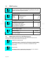

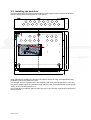
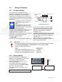
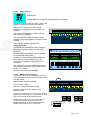
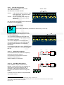
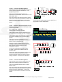
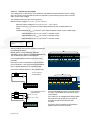
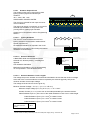
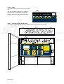
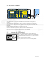
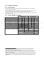
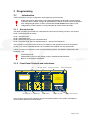
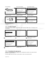


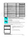

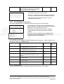


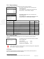
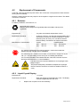


![MX2 sync [final].vp](http://vs1.manualzilla.com/store/data/005975841_1-4533d2555e3004ab9339335fb150c7a8-150x150.png)