1
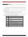
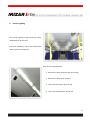
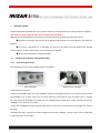
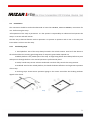
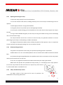
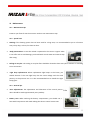
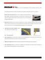
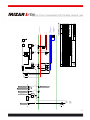
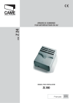
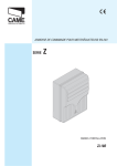
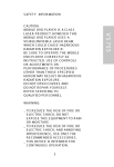
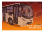
USER´S GUIDE
REVISÃO 4 – FORMATO Nº 158 – 30.07.2010
INDEX
1 DOORS
6
1.1
1.2
1.3
1.4
6
7
8
8
NORMAL WORKING OF DOORS
EMERGENCY
MAINTENANCE
DOOR’S SENSITIVITY
2 DRIVER´S CABIN
9
2.1 STARTING UP THE VEHICLE
9
3 DASHBOARD
10
3.1 ECOMASTER BASIC CLIMA
3.2 ECOMASTER BASIC D
3.3 DESCRIPTION
10
10
11
4 WIPER EQUIPMENT
12
4.1 WINDSCREEN WIPERS - MAINTENANCE
4.2 WINDSCREEN WASHER - MAINTENANCE
12
12
5 CLIMATE SYSTEM
13
5.1 ECOMASTER CLIMA
5.2 ECOMASTER BASIC D
13
17
6 INTERIOR LIGHTING
20
7 ELECTRICAL SYSTEM
21
7.1 CHANGING THE INDICATORS AND HEADLIGHT LAMPS
7.2 ROOF
21
23
8 EMERGENCY SYSTEM
24
8.1 BREAKING GLASSES SYSTEM
24
2
8.2 ROOF EMERGENCY ESCAPE HATCH
8.3 DOOR EMERGENCY SYSTEM
24
24
9 RM2 MANUAL RAMP
25
9.1
9.2
9.3
9.4
9.5
9.6
25
26
28
29
31
32
RM2 MANUAL RAMP 1000X800 ON STEP - STANDART HANDLE
INTRODUCTION
CORRECT USE OF THE RAMP
OPERATION
MAINTENANCE
ACCESS RESTRICTED TO DISABLE PEOPLE
10 AUDIO SYSTEM
33
10.1 ACT-502 RADIO CD - MP3 – USB
10.2 DRIVER MICROPHONE
33
34
11 MAINTENANCE
35
11.1
11.2
11.3
11.4
11.5
11.6
35
35
35
36
37
38
MAINTENANCE TIPS
SPECIAL CARE
GENERAL TIPS
CLEANING
PART REPLACEMENT
CLEANING INTERVAL TABLE
3
4
Delivery of the vehicle
You are now the owner of a vehicle with an Irizar body.
This User Manual will serve as guidance for the first hours of use.
It will also provide you with some maintenance advice which will enable you to extend the life of
your vehicle and make maximum use of its features.
As doubts may however arise regarding aspects of the vehicle's features, our Technical
Assistance Service are at your disposal to advise you whenever necessary.
You have received the following documentation and accessories together with the vehicle:
·
Warranty booklet
·
User Manual
·
Spares Catalogue
·
Electrical-Pneumatic Diagrams Booklet
·
List of Technical Assistance Network
·
Set of keys
This documentation can also be consulted on our web page: www.irizar.com, after sales link
In the technical documentation option of the web page, the spares catalogue and personalized
diagram booklet for your coach can be consulted, in addition to the official network. To do this,
simply register on our website as a user.
5
1
Doors
1.1
Normal working of doors
On the dashboard there is a button
for electrical operation of the front door and another for the
center door. These buttons only work when the handbrake is activated.
Note: every Irizar bus is equipped with the door’s mechanism safety system. The door will not open
when the hand brake is not activated. Before opening the doors, ensure that the hand brake is activated.
The operations of these buttons are as follows:
¦ If the door is closed, it will open when the button is pressed.
¦ If the door is open, it will close when the button is pressed.
¦ If the door is in operation, it will begin to move in reverse direction.
While the door is open, an indicator light advises of this status.
Close door
Open door
6
1.2
Emergency
The door’s mechanism is equipped with a safety system to allow the opening in case of failure of the electrical
system or during an emergency situation. In this case, the red knob located beside of the stairs can be activated. The
actuator will be free and the door can be manually opened.
1.2.1
Red outer emergency push-button
Red outer emergency push-button. Two-way valve. (2/2) NC
7
1.2.2
Inner pulser with emergency cancellation
Inner pulser with emergency cancellation
1.3
Maintenance
Work to be carried out
Frequency
Confirm the correct operation of the doors, the sensor system and the exterior
and interior emergency controls
Every 3 months
Check the coupling
Yearly
Check micro cam adjustment
Yearly
Clean air filter
Every 2 years
Lubricate actuator bar
Every 2 years
Oil exchange of the filter (Composition:95% OIL SAE-10, 5% Molybdenum Every 6 months
Bisulphide)
1.4
Door’s sensitivity
In order to avoid passengers being hurt by the doors, they are equipped with a triple sensor system which opens
the door again if it comes into contact with any obstacle while it is closing.
8
2
Driver´s cabin
Special attention has been paid to the design of the driver's cabin. Therefore, the dashboard is easily
viewed and there are no hidden controls requiring awkward movements to operate them.
The individual lighting and the independent air conditioning, forced ventilation and heating outlets have
been designed to give the driver a greater level of comfort.
2.1
Starting up the vehicle
The engine is started up using the ignition key or button, according to the chassis model.
ÙIf the engine does not start up:
¦ Check that the engine cover is correctly closed
¦ If the coach has an alarm and immobilizer system, check that they are not activated
Each coach has its own individual panel depending on the chassis and the services it incorporates.
The controls, instruments and switches on the dashboard are marked with international symbols.
The brightness of the lights of the dashboard instrument panel, tachometer, speedometer and air pressure,
oil, temperature, water and fuel level indicators can all be adjusted.
9
3
Dashboard
3.1
Ecomaster Basic Clima
3.2
Ecomaster Basic D
Recommendations for the use of Climatizer Ecomaster Comfort:
1.- Keep ALWAYS the Climatizer in AUTOMATIC
2.- The recommended temperatures are as follows:
Winter: Driver: 22ºC and Passengers: 23ºC.
Summer: Driver: 21ºC and Passengers: 22ºC.
3.- While driving, keep the driver's window ALWAYS CLOSED
4.- Every 10,000 km. CLEAN the DRIVER´S area or PASSENGERS´ area AIR FILTERS or replace them, if
necessary.
10
3.3
Description
1
2
3
4
5
6
7
8
9
10
11
12
13
14
1. Driver's lighting
2. Passenger's lighting
3. Passenger's lighting
4. Passenger's lighting
5. Control light: School,
Heated rearview mirror
6. Control light: Emergency reassembly,
Emergency call bell
7. Control light: Access ramp
8. Door emergency system
9. Pneumatic-electric horn selector
10. Emergency call bell
11. Heated rearview mirror
12. Destination sign
13. School
14. Single switch
11
4
4.1
Wiper equipment
Windscreen wipers - maintenance
Work to be carried out
Frequency
Check the wiper arms are correctly positioned and fixed
Every 3 months
Change wipers
Yearly
Check fixing screws and motor tightening torque
Yearly
Clean the unit and lubricate all joints with moving elements (with
Yearly
lithium-free grease )
4.2
Windscreen washer - maintenance
A commercial detergent, which can be purchased in specialized car shops, is recommended. Never use
household washing-up liquid, as its composition deteriorates the tubing and the rubber blodes of the
Wipers.
The windscreen washer container location is identified by the sticker below.
12
5
Climate system
5.1
5.1.1
Ecomaster Clima
Description of operation
In Air Conditioning Operation, it is possible to vary:
The temperature set for operation
§ Speed of the air in the Evaporators
§ Grilles for internal/external air
§ Switch on de-humidification
§ Block compressor inlet. (ECO)
Any variation in the speed, position of the grilles, De-humidification or Compressor blocking places the air
conditioning system in semi-automatic mode and it can be switched to fully automatic mode by pressing the
AUTO button.
5.1.2
Changing the set temperature
The Temperature can be set between 17ºC and 27ºC (63-82ºF) using the
and
keys.
When the temperature level is set below 17ºC (63ºF), the system engages forced chill mode (LO) and
activates its maximum cooling power. (the screen displays LO)
When the temperature is set above 27ºC (82ºF), the system engages forced heat mode (HI) and activates its
maximum heating power (the screen displays HI).
13
5.1.3
Varying the speed of the evaporator ventilators
The speed of the evaporators can be varied from levels 1 to 3. When the speed is altered, the system goes
into manual mode and the led located next to key
If the key
will be switched off.
is pressed, the system automatically recovers the corresponding speed and the led will shine
again to indicate manual operation.
To alter the speed, press key
. Pressing it once will display the current speed on the screen; if it is pressed
again, the value of the speed will be increased in a closed loop (from 3 it will change to 1).
Note: If the bus is not equipped with roof-mounted heaters and the interior temperature is less than 12ºC,
speed 0 may be selected while the system is warming up If speed 0 is selected manually as in the preceding
example then, once the interior temperature increases to 12.5ºC, the system will automatically take on the
corresponding speed and will set itself to Automatic.
5.1.4
Changing the grille position
The position of the grilles can be changed from external air to internal air. When the position is changed, the
system switches to manual mode.
If the key
is pressed, the system automatically recovers the corresponding position.
To alter the grilles, press key
. Pressing it once will indicate the current position; pressing it again will
change the position.
If the Ecomaster Clima is operating in air-conditioning mode and the interior temperature is 2ºC higher than
that selected (Set), the grilles will switch to Automatic mode and will close.
5.1.5
If the
Activation of ECO
key is pressed, the letters ECO will appear on screen and the compressor will be disconnected. The
system switches into Semi-automatic mode.
Pressing the
If the
or
key will have no effect if the system is not working in De-humidification mode.
key is pressed, the ECO option will be switched off.
14
5.1.6
Activation of de-humidification (reheat)
If the
key is pressed, De-humidification will be activated. This will remain in operation for 15 minutes or
until the
or
key is pressed again.
“Reheat” cannot be activated if there are no heaters installed on the roof unit.
Selecting the de-humidification option cancels out the ECO option.
5.1.7
Check temperatures
The internal and external temperatures can be checked by pressing the
key. The interior temperature is
displayed first, then the exterior temperature when the key is pressed again, and so on in a loop.
5.1.8
Variation of contrast and brightness
The values for the Contrast and Brightness can be varied and the new values will be remembered the next
time the air-conditioning unit is switched on.
For this purpose, it is necessary to use the following key combination in which the first key pressed must be
held down while the second key is pressed several times in succession to raise or lower the parameter in
question.
+
Greater brightness
+
Less brightness
+
Greater contrast
+
Less contrast
+
Factory settings for brightness and contrast
15
5.1.9
Auto checking – error codes
When the system receives the signal from the battery disconnector (+30), it first checks the outlets to check
what charges are applied and to make sure there is no short-circuit.
It also checks the status of the probes.
If any anomaly is detected, it will indicate the error(s) on the Display using the following codes:
CODE
INT. PROBE
ICE PROBE
DUCT. PROBE
EXT. PROBE
MAIN PUMP
ReCirc PUMP
COMP
ROOF VALVE
FLOOR VALVE
STEP1
STEP2
AIR
RIGHT VENT
LEFT VENT
Adj. Cond.
VENT1
VENT2
VENT3
DEMIST AIR
HEATER1
HEATER2
POT.
ERROR
Internal Probe Shorted or Open
Ice Probe Shorted or Open
Ducting Probe Shorted or Open
External Conduit Probe Shorted or Open
Main Outlet Pump Shorted
Recirculation Pump Shorted
Compressor Outlet Shorted
Roof Valve Outlet Shorted
Floor Valve Outlet Shorted
Heater Outlet Shorted Speed 1
Heater Outlet Shorted Speed 2
Recirculation Grilles Outlet Shorted
Right Adjustable Evaporator Ventilator Outlet Shorted
Left Adjustable Evaporator Ventilator Outlet Shorted
Adjustable Condenser Ventilator Outlet Shorted
Evaporator Ventilator Outlet Shorted Speed 1
Evaporator Ventilator Outlet Shorted Speed 2
Evaporator Ventilator Outlet Shorted Speed 3
Demister Recirculation Outlet Shorted
Underfloor Heater Outlet Shorted Speed 1
Underfloor Heater Outlet Shorted Speed 2
Error in the automatic setting of the potentiometer.
If any of the above errors appears, the Ecomaster Clima will start to operate in accordance with the default
operating programme. It is possible that the vehicle’s interior temperature may not be regulated correctly
under these conditions so it is recommended that the system should be reviewed by technical service
personnel.
16
5.2
5.2.1
Ecomaster Basic D
Description of operation
Ecomaster Basic D is a heating control for the driver that allows, through its keypad, the handling of
the following elements:
·
Air propulsion temperature (through the water valve).
·
Ventilation speed.
·
Grilles for internal/external air.
·
Grilles for feet/windscreen.
The control consists of 5 keys for the selection of the different functions, a bar of leds for the
indication of the temperature level required and three leds or light indicators to signal the activation of the
different elements.
By pressing key
(1) the selected temperature for the propulsion air increases. Each keystroke
increases this temperature.
By pressing key
(2) the selected temperature for the propulsion air decreases. Each keystroke
decreases this temperature.
17
The key
(3) is used to vary the speed of the air propelled by the anti-condensation fans. There
are two air speeds that are indicated by the colour of led No. 7.
The state of the fans varies according to the key pressed
(3): stopped (led off), minimum speed
(led shows green), maximum speed (led shows red) and so on.
The key
(4) is optional and it is not present in all the items in the Ecomaster Basic D family. It is
used in order to place the anti-condensation grilles so that air propulsion goes to the feet or to the
windscreen. If led No. 8 is off, this means that the air is directed to the windscreen, if it is showing red it
means that the air goes to the feet.
In order to handle the grille selecting the inlet of the outside fresh air, key
(5) must be pressed. If
led No. 9 is showing green, the grille will be placed so that the inlet of external air is allowed. On the
contrary, if led No. 9 is red, the air will be re-circulating from inside the vehicle.
The Ecomaster Basic D control will automatically close the air grilles leaving them in re-circulation
position (led No. 9 showing red) in case the temperature control for passengers requires the activation of air
conditioning. Nevertheless, the driver can open the grilles again by hand and leave them in renewal position
(led No. 9 showing green) by pressing key
(5).
The control turns off each time the electricity supply is interrupted, through the general switch
disconnection, and the activation of any outlet is impossible. As soon as it is powered on, it will turn on in
the same conditions when it was turned off, that is to say, it remembers the previous state of all of the
outlets.
5.2.2
Error detection and warning
The Ecomaster Basic D control panel includes a sophisticated system for error detection and
warning.
Each time the control is powered on, it carries out an automatic check of all the outlets.
If any problem is detected with the power supply during the following 12 seconds, it will show the
detected error through the flashing of one of the leds in the led bar No. 6. (See error table)
After any error warning, the control panel will activate those outlets which were free of errors.
In addition to error warning during the initial starting process, it is possible to check the detected
errors by pressing the keys
(1) and
(2) simultaneously.
18
There is another form of failure warning through the flashing of leds 7, 8 and 9 in the following way:
If there is a short circuit in the outlet for minimum speed, maximum speed will begin functioning
and led No. 7 will flash green.
If there is a short circuit in the outlet for maximum speed, minimum speed will begin functioning
and led No. 7 will flash red.
If there is a short circuit in the feet-windscreen grilles outlet, led No. 8 will flash.
If there is a short circuit in the outlet of external/internal air grilles, led No. 9 will flash.
A table with error codes for each of the outlets is shown below:
The column marked LED shows the led from the led bar No. 6 to be illuminated in order to show the
corresponding error. Led No. 1 corresponds to the lower led of the led bar.
LED
1
2
3
4
5
6
7
8
9
10
11
12
13
ERROR
Indicates that valve calibration is under way.
Outlet of short-circuited grounded pump.
Minimum speed outlet of fans connected due to failure to positive
power supply.
Minimum speed outlet of fans short-circuited to ground.
Maximum speed outlet of fans connected, due to failure, to
positive power supply.
Maximum speed outlet of fans short-circuited to ground.
PWM outlet connected, due to failure, to positive power supply.
PWM outlet short-circuited to ground or without connection.
(This error is shown after the initial check).
Error in the outlet of the re-circulation grille.
Error in the outlet of the feet-windscreen grille.
Error in the outlet of the water valve.
Error in return to position of valve (emergency mode).
Internal error.
Error table.
19
6
Interior Lighting
The interior lighting using fluorescent tubes,
distributed on the bus roof.
The result, durability, safety, low maintenance
and low power consumption.
Steps for exchange of lamps:
1. Remove the lamp protector part of the lamp;
2. Remove the lamp to be changed;
3. Insert the new lamp in place of old;
4. Insert the lamp protector by the end.
20
7
Electrical system
The documentation provided with your vehicle includes its personalized electrical and pneumatic diagrams.
Any electrical repairs to be carried out must be done by specialists!
Replacement of damaged fuses and relays must be done bearing the following warnings in mind:
¦ The fuses and relays must always be of identical characteristics to those shown in the electrical
diagram.
¦ If a fuse or relay blows or is damaged, the cause of the failure must be located and rectified
before replacing it with another one of the characteristics indicated.
¦ All the fuses and relays are totally standard.
7.1
7.1.1
Changing the indicators and headlight lamps
Front head lights lamps
The replacement of the front headlight lamps is as follows:
Front head light
Opened front read light
a) Open the front bonnet
b) Open the headlight like a door. The headlight swings on two hinges situated at its outermost end. To open
the headlight, turn it twice: firstly, turn it until it reaches its limit and can turn no further. Then, a second
turn will permit the headlight to be taken out of the bodywork by its lower part. Finally, continue turning the
headlight in the same way as initially.
c) Once the headlight has been opened, disconnect the connector of the lamp to be changed and remove
the lamp.
d) Change the lamp, connect the connector again and close the headlight, turning it three times as indicated
in point b), but in reverse order.
21
7.1.2
Rear lights
The procedure for changing the rear light lamps is as follows:
Motor cover
Rear lights
a) Open the motor cover
b) Remove the connecter in the socket of the lamp to be changed
c) Turn the lamp socket anticlockwise and remove it.
d) Separate the lamp from the socket and insert the new one in the socket.
e) Insert the socket in the light, turning it clockwise
f) Insert the connector in the socket
7.1.3
Front and rear clearance light replacement
The lamps are changed as follows:
Front position lights
Rear position Lights
a) Loosen the screws fixing the clearance light to the body
b) Remove the light
c) Loosen the connector and remove the socket
d) Replacement the lamp, replace the socket and connector and fasten the light to the bodywork again
7.1.4
Side lights replacement
To replacement the side light lamps, access the lights from the inside of the compartments coinciding with
each of them. Remove the socket fitted into the light and change the lamp.
22
Side indicator lights
7.1.5
Parcel racks lamps replacement
Loosen and remove the screws holding the light cover in place and remove the cover.
replacement the fluorescent tube. One of the sockets is equipped with a spring fastening system, which
must be snapped free in order to remove the fluorescent tube.
Replace the light cover and its fastening screws.
7.1.6
Stairs lights replacement
To replacement the stair light lamps the whole light
must be extracted, removing its fixing screws. When it
has been extracted, the lamp is replacement in the same
way as for the side lights on the outside of the bus.
7.2
7.2.1
Roof
Roof air inlet and emergency exit
In case of emergency the red latch must be actioned and the roof
air inlet must be pushed outwards.
23
8
8.1
Emergency system
Breaking glasses system
1st
2nd
3rd
4th
Emergency exits are
located in the side
windows indicated
by the blue light.
Remove hammer
the from the
emergency hammer
support.
break in the corner
of the emergency
window.
Press the button on
top of the support, to
return the emergency
hammer.
8.2
Roof emergency escape hatch
1st
2nd
3rd
Push up the hatch.
Remove the security seal to
unlock the hatch.
remove the escape hatch
by pushing up.
8.3
Door emergency system
Externally
To open the door in
case of emergency,
press the emergency
valve the outside.
The valve is located
on the side of the
door.
Internally
To open the door in
case of emergency,
press the internal
emergency valve.
The valve is located
inside, above the
door.
24
9
RM2 Manual ramp
9.1
RM2 Manual ramp 1000X800 on step - standart handle
Ramp for city buses
Driving: Manual
Weight: 30Kg
Static load: 375 Kg. Maximum load
capacity
Supply 24V. DC by inside/outside
voltage: ramp sensor
Safety: Handhold lock/unlock
Install: Integration into the floor of
the vehicle
9.1.1
Identification code
There is a CE normative identification plate on the inside
mobile platform where the code “Ref.” is the model.
Available in case of spare parts.
RM2 USER'S MANUAL: CGN-RM2-01-xx-2
25
9.2
Introduction
This instruction should be read and understood to know the HAZARDS, SAFETY ELEMENTS, instructions for
use… before using the ramp.
Safe operation of the ramp is paramount. It is the operator’s responsibility to understand and operate the
ramp in a correct and safe manner.
The best way to become familiar with its operation is to practise as operator and as user. In this way one
learns what it is like to use the ramp.
9.2.1
Functional groups
1. Fixed platform: Part of the ramp always located in the vehicle interior. Used to fix the device to
the vehicle whilst also ensuring good integration of ramp with ground when opened out.
2. Mobile platform: Only mobile part of the ramp. A hinge fitting allows the mobile platform to pivot
and open out through the door. This manual operation is performed by hand.
3. Inside/ outside ramp sensor: Electro-mechanical unit which fully controls the ramp position.
4. Handhold: Fixed to the mobile platform, this handle facilitates effortless and ergonomic operation
of the ramp.
5. Finishing strips: These ensure optimum signage in the access area whilst also lending aesthetic
appeal to the device.
opened out
Ramp
Ramp folded
away
26
Functional groups
9.2.2
Description of the system
The RM2 ramp is a mechanical system that is activated manually. In this model, there are the products with
references 32829xxx. The system comprises 5 functional parts which in tandem are the main assembly
units.
·
Fixed platform
·
Mobile platform
·
Inside/ outside ramp sensor
·
Handhold
·
Finishing strips
Pic.1 - Integrated in the vehicle
All the ramp elements will be integrated into the floor of the vehicle, so that no part will remain outside the
device itself. (Pic.1) The ramp sensor is powered by the bus battery and to ensure its proper functioning, the
voltage is 24V.
9.2.3
Associated sensor system
An inductive type sensor in the device’s fixed platform is used to control the ramp position,
indicating the status of the ramp at all times (open or closed).
This sensor detects the proximity of the mobile platform to the fixed platform giving a signal at
approx. 10 mm. or less distance. Operation N.O
27
9.3
Correct use of the ramp
The RM2 ramp is a platform designed for persons with reduced mobility to access the bus through
the same access door as other passengers.
The maximum load capacity is 350 kg.
Irizar accepts no responsibility for use of the ramp for any other purpose.
9.3.1
Ramp operator
The platform should be operated by a trained person. The
vehicle driver should be trained on how to use same, operating it in
accordance with the instructions in this manual and should personally
supervise use of the platform. The driver of the vehicle in which the
platform is installed is responsible for its proper use and is the only
person that should operate it.
When the ramp is needed, the driver should stop the vehicle in an area that allows the platform to
be used safely and with minimum lateral or front surface unevenness.
9.3.2
Instructions before use
Once the vehicle is positioned properly for use of the platform, the below steps should be followed
strictly to operate the RM2 ramp:
1. Stop the vehicle.
2. Engage the handbrake.
3. Notify passengers that you intend to use the ramp and request that the access area in question be
kept clear.
4. Open the access doors.
5. Go to the access door where the device is located.
9.3.3
Checks before use
Once at the access door, the driver should ensure that the location is suitable for use of the ramp
checking the following parameters:
28
1. Ensure that the device can reach the ground from the vehicle.
2. Make sure that there is nothing obstructing the ground on which the ramp platform will rest.
3. Check that the doors are fully open.
4. Check that there is nothing blocking the exit of the platform.
5. Check that there is no obstacle on the vehicle floor.
6. Clear the ramp operation and movement area.
7. Inform the user on the procedure for accessing the vehicle.
Once all the requirements have been met the driver can now open out the ramp.
From this time and until completion of the operation, the driver should remain beside the access
door paying particular attention to safety and the "environmental" conditions in accordance with the
abovementioned points.
Incorrect use of the ramp can result in personal injury.
9.3.4
Checks during use
As well as remaining beside the access door, paying particular attention to safety and
"environmental" conditions, it is important to bear in mind a series of aspects during operation:
1. Follow the instructions for use carefully and use this manual to resolve any issue that may arise.
2. Do not allow any person-user or operator-or part of their body, to be situated below or to interact
with the movement of the ramp, or to be located in a position where he/she/it may become trapped
between the platform and the ground when operating the ramp.
3. Listen for any unusual sounds during operation.
4. Watch out for any inappropriate movements/ deformations of the device.
5. Observe all the instructions and hazards on the ramp.
6. Most importantly, use common sense when operating the ramp.
7. If any anomaly is detected at this point that affects the operation of the ramp, do not use it until a
qualified technician has repaired the device.
9.4
Operation
The RM2 ramp is a simple mechanism that operates logically. In any case, the different functions or
associated modes are defined below.
29
9.4.1
Opening and closing the ramp
To open the ramp properly from its closed position:
1. Go to the outside of the vehicle, standing suficiently close to the ramp to avoid having to force it
upwards.
2. Bend slightly towards it and grip the handhold.
3. Pull gently from its rest position up to a 90º angle approximately.
4. At this point, without letting go of the handhold, use the other hand to help support the ramp at
the side.
5. Let go of the handhold and gently rest the ramp on the ground whilst moving to one side keeping
clear of its movement range.
The steps should be carried out in reverse to close the ramp. Pay particular attention to correct
positioning of your body to avoid yanking or sudden movements.
The weight of the platform always tends to follow the position of the operator. Thus, it is important
to open and close the ramp gently taking care not to trap feet or hands.
9.4.2
Ramp operating positions
For good use and operation of the ramp, two optimum operating positions are defined:
CLOSED: When not in use. The mobile platform rests on the fixed and is 100% level with the vehicle
floor.
Any element that gets trapped between the 2 platforms will result in unevenness at the rest position
and may cause vehicle users to trip over.
In any case, any significant unevenness should be detected by the ramp signal outside.
OPEN: Once the operator has operated the ramp correctly, it is considered to be in open position.
For this the ramp should rest flat and not be at a slope of any more than 12
%, which would make it unsuitable for use.
9.4.3
Safety: handhold lock/ unlock
For better control of the ramp and for ease of operation, the
handhold has a key locking mechanism.
30
Said locking prevents use of the handhold, thus preventing third parties from activating the ramp.
As a safety measure, it is recommended that the handhold be locked after each time the ramp is
used. This means that it will have to be unlocked each time it is used.
9.4.4
Safety: outside/ inside ramp signal
A sensor for controlling the ramp is located on the fixed platform of the device. This indicates the
ramp status at all times (open or closed).
This signal minimises possible damage to the ramp should one forget that it is open when closing
the door or moving the vehicle.
9.4.5
Misuse of the device
Any action that is a risk to the integrity of the device and to nearby persons is considered misuse:
·
The ramp must not be launched from a height, it must be supported and rest gently on the
ground.
·
The ramp should be properly supported by the ground. Any imbalance can result in
deformations of the ramp and is potentially dangerous for the user.
·
In a closed position the ramp there should be no obstruction between the 2 platforms. If
this should occur, the ramp will remain semi-open and may cause passengers to trip over it.
It could also become deformed if stepped on continuously under said conditions.
9.5
Maintenance
To guarantee proper operation of the system and to guarantee a long useful life of the platform it is
paramount that the entire system be kept in good condition.
9.5.1
Basic preventive maintenance
To keep the system in good condition, it is recommended that basic system maintenance be carried
out each month.
·
It is recommended that the system be kept clean and in good condition. It is thus highly
recommended that the surface of the fixed and mobile platforms and hinge be kept clean
31
Accumulation of dust, dirt, sediment, sand, mud and any other residue can cause malfunctioning of
the system and reduce the useful life of same.
·
It is recommended that during cleaning, a visual inspection of the different parts of the
platform be carried out paying particular attention to the mobile parts.
9.5.2
Complete preventive maintenance
Where timely maintenance is carried out under normal operating and soiling conditions, no other
more extensive preventive action need be taken.
9.6
Access restricted to disable people
Access restricted to disable people
32
10 Audio system
10.1 ACT-502RADIO CD-MP3 – USB
Technical Specifications
·
·
·
·
·
·
·
·
·
·
·
·
·
·
·
·
·
Radio RDS – FM, AM band – mode TA, AF
CD, CD-R, CD-RW, MP3 player
USB reader
Ampllifier 2x20 W RMS
1 Microphone priority input
1 Auxiliary audio line input to amplifly the sound from de other source
1 audio line output as additional ampliflier
Remote control IR
Power supply: 12/24V
Max. power consumption: ≤ 10A to 28 V DC / ≤5A to 14 V DC
Standy consumption: ≤9mA
Temperature in service: -20ºC to +70ºC
Vibrations: compilant with Fc IEC 68-2-6
View angle: -60º to 90º
CEM: compilant with e 13*72/245*2006/28*9925*00
Dimensions (LxHxP): 178 x 55 x 160 mm
Weight: 1,8 Kg
1 – Play the Media
2 - Select a source
3 – Pause the reproduction
4 – Stop the reproduction
5 –Fast rearward/Preview track/file
6 – Fast advanced/ Next track/file
7 – Select the play mode
8 -Change the info that displayed on LCD
monitor
9 - Receives a light signal from the remote controller
10 - Turns the Power on/off, mute
11 - Display info about the current state of player and disc
12 - Open disk
13 - Insert the USB and play the file
14 –AM and FM band
15 – Scan
16 - Memory
33
Ù Cautions
The following precautions must be taken into account:
¦ Do not expose the discs to high temperatures as this could damage them.
¦ Look after the discs by cleaning them with a soft cloth.
¦ The place the film has been stopped will be saved in the memory until the disc is removed from the CD
unit. So, if the vehicle stops and the electrical supply is turned off, unless the disc is taken out of the CD unit
the film will start again where it left off when the electricity is switched back on again, and there will be no
need to enter the disc menu to select the scene it stopped at.
10.2 Driver microphone
DYNAMIC This high-sensitivity dynamic mike is essential for passenger
announcements and is fitted with a switch in order to override all other
sources in the coach. It is easy to use and robust and its practical
qualities will be much appreciated by the driver. It is delivered as
standard with a spiral cable for connection to an ACTIA® installation, and
is also compatible with other installations by connecting an adaptor.
The amplifier detects when driver microphone is on and automatically
shut down the sound of other sources (radio, dvd, etc) over riding with
drivers.
34
11 Maintenance
11.1 Maintenance tips
Preserve your fleet for much more time. Find out our maintenance tips.
11.2 Special care
·
Heating: If the heating system has not been used for a long time, it is recommended to put it in function
every thirty days, at least, for about an hour.
·
Body preservation: In case the vehicle is operated in the coast or regions when
it can suffer salt or sand damage, you should wash it with water and neutral soap
after using.
·
Ceiling air recycler: The ceiling air recycler filter should be cleaned at least every three months or according
to use necessities.
·
Light lamp replacement: When replacement light lamps in the buses, you
should observe if the new light lamp has the same voltage and the same
potency as the previous one. It is also recommended not to handle the light
lamps glass.
11.3 General tips
·
Door adjustments: The adjustments and lubrication of the control points of the
doors should be made approximately every 30 days.
·
Battery case: When washing the battery compartment, you should use a
hose with low pressure and avoid making the electric control circuits wet.
35
·
Lubrication of components: See the table below the frequency of lubrication of
components, well as the type of lubricant to each piece.
·
Refastening the seats: Refastening the seats should be made every three months.
·
Radio volume: To control the sound, you should put the radio
volume in its capacity of 60% and control the sound volume
through a selecting button.
11.4 Cleaning
·
Seats, upholstery and structure: Vacum clean surfaces once a week. To keep upholstery in good condition, a
monthly thorough cleaning is required. Damp sponges and washing-up
detergents are preferred for cleaning upholstery. To avoid drying problems,
don't left water soak into upholstery. Check seat floor screws once a month,
tightening them when required.
·
·
Glass cleaning: The glass should be cleaned preferably with products based on alcohol or ammonia. When in
lack, you can use water and liquid soap, rubbing the glass with flannel.
·
External cleaning: It is recommended to apply silicon wax or similar every three months. If, during the
cleaning, the water does not accumulate in drops on the paint, the vehicle could be waxed after drying.
·
Interior cleaning and up keeping: Cleaning bus interiors with water jets results in water accumulation on the
floor and damp tiles. Avoid using kerosene, gasoline, and the like. Clean the interior with a wet cloth and
vacum cleaner. Clean stained flooring or paneling with a wet cloth and washing-up liquid. Attention: never
try to clean the interior with a water jet.
·
Plastic Parts: Clean plastic parts with benzene, family pharmacy alcohol or soap and water.
36
The following should not be used to clean plastic parts: gasoline, fuel alcohol, kerosene, or acetone.
Covers front, rear and side: These covers should be reviewed quarterly.
Check hinges, operating and fixing bolts, and make thin oil lubrication. Also
check the conditions of the rubber, Replace the foam covers, if they have any
damage or deformation.
·
Battery box: The battery box should be cleaned every six months. Carefully note which cable connects to
which terminal to avoid the risk of misconnection and consequent serious damage to the electric circuits.
Use a solution of 3 1/2 oz. of drugstore sodium bicarbonate in one quart of water.
·
Horizontal and vertical handrails: Clean
with a damp cloth and ordinary soap.
11.5 Part replacement
·
Doors adjustment: Be careful when closing and opening adjustments of the door. There should be an
opening of approximately two millimeters between the jambs.
·
Windscreen replacement: Rubbers should be cleaned before assembling the new windscreens.
·
Glass replacement: When it is necessary to substitute the fused glass, you should, before removing the
glass, remove all finishing elements, internal and external.
37
11.6 Cleaning interval table
D = Daily
W = Weekly
Item
Q = Every Quarter
Clean
Driver screen, handrails, seats
W
Driver
D
Battery box
M
M = Monthly
Lubricate
M
Tighten
Adjust
W
W
M
W
Windshield clearing system
W
Inside / outside rear view mirrors
M
Headlights
Outside front grill
W
Windshield wipers
Cleaning
Check
M
W
Q
W
M
W
M
W
D
Lights (indicator/brake/tail/brake-light)
D
Front/rear bumpers (screws / plates)
M
W
Floor (screws / section)
M
W
W
W
Floor
D
Seats
W
Doors
M
Outside paneling (painting)
W
Inside paneling (Formidur ceiling / sides)
W
Covers
Locks
Glasses
D
W
Q
Q
W
Q
M
W
M
W
W
38
39
BL
YE/GR
250
M
C691.4
Engine Hatch open
I
ENGINE
COVER
SWITCH
POSITIVE
ACTIVE
0.75
031
C691.4
A3.5
0.75
031
0.75
327
Handles
Adaptation
R
Door signal (-) Dashboard Control
ENTRANCE DOOR OPEN
AC Compressor
CCC.5
0.75
503
A2.7
0.75
511
0.75
511
C691.13 C691.2 C691.10 C690.10
35
RD
FAA
100A
FC
50A
25 000
RD 4
FD
30A
Ignition key on
4
C 690
G3
1
R
R
G3
A1.3 A1.4
11
CHASIS
G3
4
Firma
Fecha
R
A2.15
Proyectado
A1.6
-
F40
5A
A1.2
F27
5A
F26
5A
ESCALA
IZAGIRRE
15/05/2007
-
Comprobado
G0
+
Dibujado
D012
Xabier
15/05/2007
1.5
117
9
Position
light
+
General Power Scheme Scania K420 Euro IV
Denominación
29E463ns0
A3
31
0.75
002
6
Clase de modificación
Nº de plano
A1.5
DIN
Nº
2
0.75 0.75
013 066
3
G0
86
CHASIS
VEHICLE SPEED FIXED VALUE
5KM/H
30
30a
C 690
ACTIVATED BUS BRAKE
From Door scheme
R007
C 693
Power Supply
CHASIS
Fecha
Sustituido por el Nº
Sustituto del Nº
ORMAIZTEGUI
IRIZAR, S. Coop.
Firma
Ref. IRIZAR
+15 ENGINE STARTED
AIR CONDIT
000 +BAT
+15
ENGINE STARTED
+15
WC
+58T
+58
+30 AIR CONDITIONED
+30
+58
1.5
137
A1.10
D1.8
A1.11
D1.9
L025
B7
B7
L030
0.75
136
3
1.5
136
L021
L010
G1
Nº
0.75
136
0.75
137
Nº de plano
DIN
B3.8
0.75
137
L026
0.75
137
L029
Firma
Proyectado
Firma
Fecha
B3.7
G1
Clase de modificación
29E474ns0
A3.9
4
L022
G1
A3.8
0.75
1371
1.5
137
L009
G1
7
0.75 0.75
1361 1371
0.75
1361
0.75
136
1
Right
blinker 1
CHASSIS
10
1.5
136
Left
blinker 1
C695
1
Right
blinker
CHASSIS
C693
Left
blinker
Dibujado
Comprobado
P.Fontes
21/11/2006
21/11/2006
Denominación
Fecha
IRIZAR, S. Coop.
ORMAIZTEGUI
BLINKER SCHEME SCANIA K420 SERIES
A4
ESCALA
Sustituto del Nº
Sustituido por el Nº
40
41
L
AUXILIAR LIGHT
CM1
0.75
153
B3.10
B7.8
4
10
CM1
4
T
449
2
B 7.7
B3.1
F9
7.5A
1.5
141
CM.2
S1.8
1.5 1.5
153 152
S1.9
+30
+58T
+58
7
5 3 8 6 1
REAR FOG LIGHT
II 0 I
T
450
404
D
1.5
106
CM1
1.5 1.5
BK BK
G3
405
D
D1.10
6
3
B7.3
3
6
CM1
451
T
1.5
138
1.5
125
B3.4
R
478
T
7
F6
7.5A
10
7
A1.14 A1.21
1.5
141
FRONT FOG LIGHT
F10
7.5A
CM1
6
6
454
T
453
T
4
1.5
140
4
B7.6
B3.5
A3.7
471
T
0.75 1.5
126 138
A1.13
10
7
1.5
125
1
3
452
T
0I
STOP LIGHT
1
REVERSE LIGHTS
1.5
140
4
3
426
T
0.75
110
CM1
5
1
B7.1
B3.3
A1.7 A1.8
C695
ENGINE LIGHT
3
LEFT REAR PARKING LIGHT
0I
455
T
1.5
BK
CM1
459
D
1.5
102
462
D
1.5
BK
1.5
103
1.5
BK
0.75
111
5
CM5
DIN
CM6
410
TE
0.75
156
T1.14
137
I
7
3
1.5
242
S3.21
0I
1.5
567
6
1.5
236
CM6
T1.20
F48
5A
S3.19
10
1
C694
432
D
132
I
Clase de modificación
Nº de plano
Firma
Fecha
Dibujado
P.Fontes
21/11/2006
Exterior Signalitation SCANIA K420
Denominación
29E483ns1
Proyectado
LICENSED PLATE LEFT PARKING RIGHT PARKING DESTINATION
LIGHTS
LIGHTS
LIGHTS
PLATE LIGHTS
419
T
472
T
409
TE
0.75
155
T1.12
Cambio posicion cables antenieblas
3
1
A3
1
Nº
CM1
456
T
1
0.75
111
B7.2
B3.3
A1.12
1.5
111
D1.2
CM1
460
D
1.5
103
D1.4
1.5
101
D1.6
7
CHASIS
A1.18 A1.16
1.5
101
4
CM1 CM1
1.5
BK
461
D
1.5
100
D1.5
1.5
100
8
D1.3
0.75
110
D1.1
1.5
102
3
A1.15 A1.17
9
A1.9
1.5
110
2
LEFT FRONT DIPPED BEAM
C693
LEFT FRONT PARKING LIGHT
AUX
I
LEFT FRONT MAIN LIGHT
102
I
RIGHT FRONT MAIN LIGHT
108
I
RIGHT FRONT DIPPED BEAM
+58
RIGHT FRONT PARKING LIGHT
CHASIS
7
ES CALA
21/11/2006
Comprobado
0.75
568
1.5
563
668
0.75
568
N1.9
1.5
563
D1.7
A1.19 A1.20
G2
0.75
567
N1.8
A3.1
G2
10
1
1.5
BK
850
G1
15/05/2008
Fecha
Sustituido por el Nº
Sustituto del Nº
ORMAIZTEGUI
IRIZAR, S. Coop.
P.Fontes
Firma
SEÑALIZACION EXTERIOR
4
5 3 8 6
PNEUMATIC
HORN
0I
42
+30
+15
+58
000
+58T
G3
0I
10
7
0.75
572
CM7.7
CM7.16
1
3
0.75
572
G3
0.75
572
EMERGENCY HAMMER
(OPTIONAL)
W005
D
W005
F24
10A
10
9
CM7.22
7
3
S3.2
0.75
542
10
9
10
1
Escape Hatch
Buzzer
Sensor
5
0.75
608
1
O I
CV8.8
0.75
541
0I
5
0.75
608
1
O I
0.75
149
0.75
149
27
0.75
149
CV16.7
Escape Hatch
LED
CM7.6
R
CM2.21
F19
5A
0.75
013
Chassis
Main
Switch
Relay
time
15min.
D017
Red light
Emergency knob
Front Door
0.75
149
A3
DIN
Nº
Emergency
Exit
Firma
Fecha
Proyectado
CV16.4
Dibujado
CV17.7
F20
5A
CM7.20
1.5
234
AUSTRALIA WARNIG SYSTEM - IRIA
Denominación
29E783
Nº de plano
Clase de modificación
Emergency
Exit
F37
5A
CM7.21
1.5
000
TICKET
MACHINE
ESCALA
Comprobado
Fecha
Sustituido por el Nº
Sustituto del Nº
ORMAIZTEGUI
IRIZAR, S. Coop.
Firma
Ref. IRIZAR
+58
3
0I
1
7
1.5
511
10
1.5
127
0.75
127
1.5
235
S3.4
+30
133
I
133
I
S3.10
F4
10A
1.5
511
Relay
E
0.75
511
3/6
5/6
1 642 5 3
1/6
6/6
4/6
0.75
136
0.75
137
FRONT
1.5
Res
1.5
Res
REAR
Ref. IRIZAR
SCHOOL
LIGHTS
Nº
Clase de modificación
Nº de plano
29E864ns0
DIN
Firma
Proyectado
Firma
Fecha
Dibujado
Comprobado
P.FONTES
08/09/2008
08/09/2008
Denominación
Fecha
IRIZAR, S. Coop.
ORMAIZTEGUI
SCHOOL LIGHTS AUSTRALIA
A4
ESCALA
Sustituto del Nº
Sustituido por el Nº
43
+58
I OII
1 7 2 8 9
3
1.5
40
4
1.5
597
10
G
1.5
593
CM2.7
CM2.2
CM2.3
+30
F22
10A
1.5
597
1.5
40
1.5
593
CV18.2
CM4.9
CM4.10
1.5
597
1.5
593
LIGHT
DRIVER
L
G
V003
P
PRESSURE SWITCH FOR
FRONT OPEN DOOR DETECTION
DOOR. 6
+58
Ref. IRIZAR
Nº
Clase de modificación
Nº de plano
591560MA0
DIN
Firma
Proyectado
Firma
Fecha
Dibujado
R.FOGUERAL
14/05/2009
Comprobado
Jon Lasa
14/05/2009
Denominación
Fecha
IRIZAR, S. Coop.
ORMAIZTEGUI
DRIVER´S LIGHT
A4
ESCALA
Sustituto del Nº
Sustituido por el Nº
44
+58
G
1,5
42
I
O
1
9
S003
S003
5
10
5
10
5
1,5
306-1
1,5
305-1
CM2. 9
9
1
CM2
I O
CM2.4
CM2. 5
+30
1,5
305-1
CV5
F27
10A
1,5
42
START BUS
CV1.4
4
1,5
306-1
R
7
R
F7
10A
G
F31
10A
CV5
1,5
42
F5
10A
9
3
CM6.2
CM4. 12
F33
10A
3
9
1,5
306
1,5
306
CM6.3
CM4.13
1,5
306
3ª 5ª Y 7ª RHD FLUORECENT TUBE
1,5
305
2ª 4ª y 6ª LHD FLUORECENT TUBES
2ª 4ª y 6ª RHD FLUORECENT TUBES
1,5
305
1,5
306
3ª 5ª Y 7ª LHD FLUORECENT TUBE
2
CV7
CV17
5
Ref. IRIZAR
Nº
Clase de modificación
Nº de plano
591562MA0
DIN
Firma
Proyectado
Firma
Fecha
Dibujado
R.FOGUERAL
14/05/2009
Comprobado
Jon Lasa
14/05/2009
Denominación
Fecha
IRIZAR, S. Coop.
ORMAIZTEGUI
INTERIOR LIGHT´S
A4
ESCALA
Sustituto del Nº
Sustituido por el Nº
45
G
G
1.5
BK
1.5
BK
G
0.75
32
1,5
34
0.75
32
CM4.2
CM1. 9
0.75
32
CM4.3
1
R
21
4
1,5
36
1,5
36
CM4.5
CM4.1
CM3.15
CBB3
1,5
30
RELAY TO SWITCH
POSITIVE AND
NEGATIVE FOR VOLVO
1,5
35
2
6
7
CHA SIS
1,5
36
1,5
34
0.75
32
9
G
DOOR´S DIAGRAM
CM6.4
CV17
1,5
34
CV28
F26
10A
CV28
+30
1
1,5
36
STOP
4
3
5
Ref. IRIZAR
Nº
Clase de modificación
Nº de plano
591563MA0
DIN
Firma
Proyectado
Firma
Fecha
Dibujado
R.FOGUERAL
14/05/2009
Comprobado
Jon Lasa
14/05/2009
Denominación
Fecha
IRIZAR, S. Coop.
ORMAIZTEGUI
STOP REQUESTING SYSTEM
A4
ESCALA
Sustituto del Nº
Sustituido por el Nº
46
V01
CM5.8
6
G
9
8
1
G
2
4
G
SWINGING ELECTRONIC
RELAY
E016
FRONT DOOR
R
CHASIS
C690
5
1.5
592-1
CM5. 3
19
CONTROL
PUERTAS
4
6
9
2
8
G
1.5
166
CM5. 7
1.5
309
9
1.5
309
CM3.12
CHASIS
O PEN
DOOR
V02
V03
OPEN DOOR
PILO T LIGHT
I O
CM5.12
1.5
189-P
1
1.5
309
1.5
309
9
1.5
189
5
1
10 S1
CM5.18
RAMP
SE NSOR
T1
L1
3
1.5
RAMPA
2
9
F15
10A
15
G
R
4
6
G
2
G
G
C690
1
0.75
10.2
1
CM3. 22
G
1.5
RAMPA
1.5
691
CV4
Ref. IRIZAR
DOOR
LIG HTING
4
5
G
P
1.5
692
V5
20
A3
1.5
35
CV12
CM3.13
I O
G
Nº de plano
1.5
166
1
1.5
190
G
Firma
Fecha
10
2º DO OR
SWITCH
F4
10A
1.5
691
9
3
1.5
190
5
12
6
R
7
5
1.5
309
ESCALA
Comprobado
1
10
G
Firma
L01
DIO DES BOX
REAR DOOR
1.5
692
R
REAR DOOR
MECHANISM
COVE
1.5
593
G
F10
10A
ORMAIZTEGUI
Sustituido por el Nº
Sustituto del Nº
1.5
166
6
G
STAIRS
LIGHT
DIO DES BOX
REAR DOOR
1.5
592
Fecha
9
CV10
IRIZAR, S. Coop.
OP EN DOOR
(-)
JANDERSON
14/05/2009
OPEN DOOR
(+)
O PEN DOOR
LIGHT
L2
CV10
1.5
35
G
1.5
691
4
1.5
SENAL
VELOCIDAD
6
TACOG RAPH
SI GNAL 3Km/h
CM3. 17
V07
1.5
BK
Dibujado
V06
V05
9
CV12
1.5
166
8
1.5
189-P
CM1.2
FRONT DOOR
SWITCH
1 E XTERNAL
R.FOGUERAL
14/05/2009
4
1.5
166
1.5
309
1.5
309
I O
1.5
1.5 1.5
592.1 593 311
G
1
CM1.1
CM5.9
CV12
Proyectado
2
G
6
REAR DOOR
DOOR SYSTEM - IRIZ
Denominación
2
1.5
190
5
1
V6 V7
1.5
BK
1.5
190
Clase de modificación
591564MA0
DIN
Nº
0.75
081
S2
STOP
REQUESTING
DIAGRAM
1.5
166
CM5.5
1.5
692
7
EMERG.
BUTTON
I NTERI OR
REAR DOOR
G
V9 V8
1.5
692
4
R
1.5
691
CV27
CM3.11
DIS ABLES
RAMP LIG HT
S033
EMERG .
BUTTON
INTERIOR
FRONT DOOR
G
CV27
G
1.5
RAMPA
EMERGENCY
RE-ACTIVATION
REAR DOOR
G
0.75
12
3
V4
0.75
16.2
2
CV4
2
0.75
081
CM2.16
XXXXX
0.75
16.2
0.75
081
0.75
10.2
1
4
R
11
0.75
081
CM1. 22
V04
EMERGE NCY
DIODES BOX REAR DOO R
FRONT DOOR
DRIVER´S LIGHT
DIAGRAM
CM5.2
1º DOOR
SWITCH
F18
10A
1.5
189
1.5
1.5 1.5
311 592-1 593
1.5
BK
7
1.5
166
CM3.16
1.5
166
10
E017
G
V2 V3
1.5
189
3
1.5
189
7
CM5.14
CV30
1.5 1.5
311 166
CM5.10
R
10
CM3.18
EMERGENCY
REACTI VATION
SWITCH
10
F9
10A
9
SWINGING ELECTRONIC
RELAY
EMERGENCY
RE-ACTIVATION
FRONT DOOR
2
0.75 G
16
5
1
C690
CENTRAL SAFETY
HANDBRAKE
CONTROL
(+)
SWT POW GND OUT1 OUT2
V1
0.75
16.1
P
G
0.75
10.1
2
CM2.14
0.75 0.75
10
16
0.75 0.75
10.1 16.1
1
000
+30
+15
+58
CM2.13
0.75
10
I O
CV15
S032
CHASIS
CV30
C691
CV30
C691
FRENO
PARADA
CHASIS
CV4
OPCIONAL SI GNAL
SCANIA NO CONNE CT
CV27
C690
DO OR CONTROL
SCANIA
CV27
EMERGENCY
PILOT LIGHT
C1
CV9
C2
CV16
C3
CV12
CONNECT
TO CABLE 541
P
CHASIS
CV10
+58
CV10
CHASIS
CV4
8
EMERGENCY
FRONT DOOR
CV4
C4
1
REAR
DOOR
CLOSE
5
P
4
P
C5
8
P
6
P
CV10
3
SWT POW GND OUT1 OUT2
47
L002
RADIO
N001
AMPLIFIER
2.5
BK
2.5 0.75
82 309
0.75 0.75
610 611
0.75 0.75
612 613
610 611
612 613
CM5
CM4
G
7
2
8
F17
10A
CV16
F29
10A
CV17
+30
000
1R
2R
3
610 0 .75
612 0 .75
6102 0 .75
6111 0 .75
6122 0 .75
6130 0 .75
6102 0 .75
6130 0 .75
6104 0 .75
6131 0 .75
6111 0 .75
6113 0 .75
3R
STANDARD 12.2 m
6104 0 .75
6113 0 .75
4R
DRIVER
1L
6122 0 .75
6124 0 .75
2L
6131 0 .75
6133 0 .75
3L
6124 0 .75
6133 0 .75
4L
EQUIPO AUDIO Y VIDEO
Nº
Clase de modificación
Nº de plano
591567MA0
DIN
A3
Firma
Proyectado
Firma
Fecha
Dibujado
Jon Lasa
14/05/2009
Comprobado
Jon Lasa
14/05/2009
Denominación
Fecha
IRIZAR, S. Coop.
ORMAIZTEGUI
RADIO SYSTEM
ESCALA
Sustituto del Nº
Sustituido por el Nº
48
+58
0I
1.5
236
3
1
7
10
1.5
236
G
CM7.15
+30
F3
10A
1.5
236
CM7.14
1.5
236
1.5
236
1.5
236
1.5
236
CONTROL
DISPLAY 3
DISPLAY 2
DISPLAY 1
Ref. IRIZAR
Nº
Clase de modificación
Proyectado
Nº de plano
591578MA0
DIN
Firma
Firma
Fecha
Dibujado
R.FOGUERAL
14/05/2009
Comprobado
Jon Lasa
14/05/2009
Denominación
IRIZAR, S. Coop.
ORMAIZTEGUI
HANOVER DESTINATION DISPLAYS
A4
Fecha
ESCALA
Sustituto del Nº
Sustituido por el Nº
49
+58
0I
1.5
41
3
1
7
10
S004
G
1.5
307
CM2.6
CM2. 8
+30
F23
10A
1.5
41
1.5
307
CV18.5
1.5
307
CM6. 1
LHD
F LUORES CENT
TUBE
RHD
FLUORE SCE NT
TUBE
CM4.11
L031 L032
G
Ref. IRIZAR
Nº
Clase de modificación
Nº de plano
591580MA0
DIN
Firma
Proyectado
Firma
Fecha
Dibujado
R.FOGUERAL
19/07/2010
Comprobado
Jon Lasa
19/07/2010
Denominación
Fecha
IRIZAR, S. Coop.
ORMAIZTEGUI
AISLE LIGHTS
A4
ESCALA
Sustituto del Nº
Sustituido por el Nº
50