1
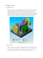
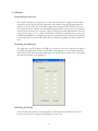
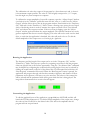
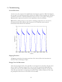
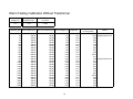
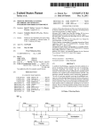
Mechanical Oscillator
User Manual
Franklin W. Olin College of Engineering
Olin-NASA Research Group
Summer 2005
Table of Contents
1 – Quick Start Guide...................................................................................................................................3
2 – Oscillator Assembly................................................................................................................................5
3 – Amplifier Circuit and Transformer......................................................................................................7
4 – Software....................................................................................................................................................9
5 – Troubleshooting....................................................................................................................................11
6 – Components..........................................................................................................................................12
7 – Frequency Response Report...............................................................................................................18
8 – Drawing Files........................................................................................................................................21
9 – Suppliers.................................................................................................................................................23
10 – Acknowledgements............................................................................................................................23
2
1 – Quick Start Guide
1 - Mount oscillator to target object with 6-32 size screws
The oscillator assembly should be mounted to the target object using 6-32 size screws. The
base plate of the assembly has four through holes, one at each corner, dimensioned to
accommodate these screws. The assembly should be attached using all four of these holes to
ensure a strong connection.
2 - Connect blue and green transformer leads to orange leads on amplifier circuit
The blue and green leads coming from the transformer, which is mounted to the base plate,
must be attached to the orange leads coming from the bottom of the amplifier circuit. Since
the amplifier circuit was designed to function at normal room conditions, these connections
must be made via a feedthrough to the outside of the dewar.
3 - Attach ± 18 V power supply to amplifier circuit
Connect a ± 18 V power supply to the amplifier circuit via banana clips. The +18 V lead
should be plugged into the red port labeled with a “+”. The -18 V lead should be plugged
into the red port labeled with a “–”. A grounded lead should be plugged into the black port.
4 - Attach the amplifier circuit to a computer via a 3.5 mm mono audio cable
Plug a 3.5 mm mono audio cable into the small black audio port on the amplifier circuit. The
other end of this cable should be plugged into the audio port of a computer that supports
MATLAB 7.0.
5 - Open MATLAB 7.0 and run control.m
Open MATLAB 7.0 and navigate its current directory to the folder containing control.m and
control.fig. Type control into the MATLAB interface to launch the program.
6 - Calibrate the output of the control program
Set the sound card volume on the computer at a value that corresponds to the normal
listening volume of the computer if head phones were in use. Set the output amplitude to 1
by opening the “Adjust Output” window in the “Calibrate” pull down menu. Close the
“Adjust Output” window. Select the top line in the program window. Enter 2000 in the
“Frequency (Hz)” field and 5 in the “Duration (s)” field. Connect a floating scope across the
two output wires of the ampllifier circuit in order to measure the output waveform. Click
“Test Selected Line” and observe the output waveform. If the wave form is clipping, open
the “Adjust Output” window again and reduce the output amplitude. The oscillator
functions best at the greatest amplitude that does not result in clipping. This calibration
should be done at the beginning of each use.
3
7 - Run program with desired frequencies
In the control program window, input the desired frequency and time duration of the signal.
Up to five signals can be played sequentially. Click “Run Program” to begin driving the
oscillator. The frequency currently being played should become green.
4
2 – Oscillator Assembly
Assembly Overview
The solid model shown below is graphical representation of the oscillator assembly. This
assembly is intended to be placed inside the dewar and operate at 4 K. This assembly was
tested at temperatures as low as 77 K, at which it was still fully functional. At room
temperature, the oscillator was found to able to produce vibrations that, when attached to a
10 kg mass, would have magnitudes on the order of mG’s. The assembly was found to have
resonances at 530 Hz as well as 2500 Hz. At these frequencies, vibrations of approximately
30 mG’s were predicted. Details of the experimental data can be found in Section 7.
Oscillator System
The actuator used in this system is a moving magnet linear actuator purchased from H2W
Technologies. This actuator functions on the principle of a voice coil. The lead countermasses mounted to each end of the moving magnet are approximately 25 g. This mass is
great enough to produce accelerations on the order of mG’s on a 10 kg mass.
5
Compression springs were placed along the magnet between the counter-masses and the end
of the actuator casing. These springs keep the magnet centered within the voice coil without
substantially affecting its travel. The transformer connects the actuator to the amplifier
circuit, which is kept outside of the dewar. Details about the function of the transformer
can be found in Section 3. Specs for all of these components are available in Section 6.
Mounting System
The mounting system for the oscillator assembly consists of three main parts, two actuator
grips and a base plate. These pieces were cut from 1/4” 1018 steel. This is the same steel of
which the casing of the actuator is made. This prevents any damage to the actuator that may
have otherwise occurred due to thermal contractions. Drawing files for these parts are in
Section 8.
Assembling the Oscillator System
To begin assembling the oscillator system, the actuator should be placed through both of the
actuator grips. The grips should then be generally positioned over the threaded holes in the
base plate. Two 1/4” long, size 4-40 screws may be used to attach the grips to the base plate.
Each screw should be screwed in to half its length before any of the screws are tightened. A
size 4-40 Belleville washer should be placed between the head of each screw and the grip to
ensure tight connects after thermal contractions.
The actuator can be secured in the grips by placing a 1” long, size 4-40 screw through the
holes in the top of the grip and tightening a nut on the other end of the screw. Belleville
washers should be placed between the heads of the screws and the grips as well as between
the nuts and the grips.
After the actuator is secured, the centering springs may be placed along the moving magnet
as described previously. Next, the counter-masses should be attached. These masses are held
on to the magnet via 3/8” long, 2-56 size screws. Size 2-56 Belleville washers should be
placed on either side of the mass before screwing the mass to the magnet.
Attaching the Assembly to the Target Object
The oscillator assembly should be mounted to the target object using 6-32 size screws. The
base plate of the assembly has four through holes, one at each corner, dimensioned to
accommodate these screws. The assembly should be attached using all four of these holes to
ensure a strong connection.
6
3 – Amplifier Circuit and Transformer
Circuit Overview
The circuit diagram below is a graphical representation of the amplifier circuit. This circuit is
a current driven operational amplifier circuit. A current driven circuit was desirable because
it prevents the voice coil current from varying as the resistance of the feed through wiring
varies. The op-amp used in this circuit was an OPA551 (See op-amp specs in Section 6). The
transformer shown in the circuit diagram is actually separate from the amplifier circuit. It is
attached to the base plate of the oscillator assembly and is placed inside the dewar. This
transformer was necessary to connect the voice coil to the high impedance wiring within the
dewar. This is because the voice coil works more efficiently with a high current and a low
voltage.
Circuit Diagram
Connecting the Circuit
The amplifier circuit should be connected to a ± 18 V power supply via banana clips. Higher
voltages may result in op-amp failure even though it is rated to ± 30 V. A 3.5 mm mono
audio cable should be plugged into the signal input port. The other end of this cable should
be plugged into the audio output port of the computer that is supporting the oscillator
control software.
7
The orange output leads of the amplifier circuit should attach to the blue and green leads of
the transformer via a feed through on the dewar. Each connection port/wire is labeled in the
diagram below.
Performance
In room temperature testing, the circuit was found capable of delivering high quality
waveforms to the oscillator over the majority of the desired frequencies (60-2000 Hz). This
waveform had an amplitude of approximately 400 mA. Details of experimental data can be
found in Section 7. The quality of the voice coil current waveform should improve
significantly at cryogenic temperatures (4 K) because the resistance in the wiring of both the
transformer and the voice coil becomes negligible. This improvement may allow for high
quality waveforms at frequencies as low as 20 Hz.
Replacing Components
Note: Before making changes to the circuit or adjusting components, be sure that it is
disconnected from the computer and the power is off. Otherwise, power may be
inadvertently back-fed into the computer.
Over the course of its use, some components in the circuit may burn out or otherwise break.
The OPA551 can be replaced by simply pulling out the damaged one and pushing a new one
into its place. It is important to orient the replacement op-amp such that the semicircular
notch on the op-amp is close to the positive input terminal. All other components must be
removed by melting away the solder that holds them in place.
8
4 – Software
Control Program Overview
The control software was designed to be easily customized and to operate within multiple
operating systems. Developing the application and interface using MATLAB permits the
software to be run from any system that supports this program (OSX, Windows XP, etc.).
The output from the software was directed through the audio output port of the computer
because the sound card on a computer outputs a relatively accurate reproduction of sound
sources in the range of ± 1 V. Since sound cards on different computers may output waves
of different amplitudes, a configuration option was included that would alter the amplitude
of the output wave as to provide similar output conditions regardless of which computer is
used.
Launching the Application
The application was developed in GUIDE, so it consists of two files, control.fig and control.m.
To launch the application, navigate MATLAB’s current directory to the folder containing
both of these files, then either type control into MATLAB or run the .m file. This causes
the following window to be displayed.
Calibrating the Output
Set the sound card volume on the computer at a value that corresponds to the normal
listening volume of the computer if head phones were in use.
9
The calibration tool scales the output of the program by a factor between 0 and 1, where 1
is the maximum output possible. The value of 1 will roughly correspond to ± 1 V output,
but this might vary from computer to computer.
To calibrate the output amplitude of a specific computer, open the “Adjust Output” window
(seen below) in the “Calibrate” pull down menu. Set this value to 1, and Close the “Adjust
Output” window. Select the top line in the program window. Enter 2000 in the “Frequency
(Hz)” field and 5 in the “Duration (s)” field. Connect a floating scope across the two output
wires of the driving circuit in order to measure the output waveform. Click “Test Selected
Line” and observe the output waveform. If the wave form is clipping, open the “Adjust
Output” window again and reduce the output amplitude. The oscillator functions best at the
greatest amplitude that does not result in clipping. This value will not be saved onto the hard
drive, so each time the application is launched, this value will need to be set. To edit the
default amplitude of the output wave see Customizing the Application.
Running the Application
The frequency and the length of the output can be set in the “Frequency (Hz)” and the
“Duration (s)” fields. There are two options for outputting sound waves with the program:
either one specific line or all five lines sequentially. Using the “Test Selected Line” command
may be helpful for configuring the oscillator before testing begins. Lines may be selected by
clicking the round button on the left of the desired line. For substantial data collection, the
“Run Program” command will be useful. When the “Run Program” button is pressed, the
application will progress through each line that contains a frequency and duration. If these
parameters are not present, it will move on to the next line. The button of the current line
will be selected and the parameter fields will be green while that line is being played. The
image below demonstrates how an active line will appear.
Customizing the Application
To edit the graphical layout of the application, type guide into MATLAB, and this will
launch the GUI development tool. To edit the default amplitude of the output wave, change
the value on lines 22 and 201 to the desired value. This will be the amplitude that the
program will run at upon launch.
10
5 – Troubleshooting
Unusual Waveform
In some cases, the output of the amplification circuit appears as below. When this happens,
the op-amp is not functioning properly and must be replaced. When replacing the op-amp, it
should be positioned so that the semicircular notch is closest to the positive voltage port.
Replacing this component should solve the amplification circuit’s problems.
Note: Before making changes to the circuit or adjusting components, be sure that it is
disconnected from the computer and the power is off. Otherwise, power may be
inadvertently back-fed into the computer.
Clipping Waveform
If clipping is noticed on the output waveform of the circuit, follow the instructions in
Section 3 under Calibrating the Output.
Choppy Voice Coil Movement
If the moving magnet in the voice coil clicks or no longer moves smoothly, this may mean
that it is dirty or otherwise clogged. The voice coil may be opened and cleaned. Before
opening the voice coil, the counter-masses and springs should be removed. To open the
voice coil, note that there is a snap ring on one side of the oscillator. Removal of the snap
ring with pliers allows access to the inside of the assembly.
11
6 – Components
Oscillator System
Actuator
Non-Commuted Direct Current Moving Magnet Linear Actuator from H2W Technologies
P/N: NCM02-05-005-4JB
Serial: G501
See Section 8 for drawing and dimensions
o
o
o
o
o
o
o
o
o
o
o
o
o
o
o
Power Rating: 3.5 W
Voltage Rating: 3.5 V
Current Rating: 1 A
Casing Material: 1018 Steel
Magnet Travel: 0.15”
Max. Acceleration: 20 G
Continuous Force: .5 lbs.
Peak Force: 1.5 lbs.
Average Km: 0.27 lbs./W1/2
Total Mass: 0.067 lbs.
Moving Mass: 0.026 lbs.
Inductance (Room Temp.): 0.2358 mH
Inductance (77 K): 0.2262 mH
Resistance (Room Temp.): 3.38 Ω
Resistance (77 K): 0.649 Ω
12
Centering Springs
Compression Springs from Century Spring Corporation
P/N: 10572
o
o
o
o
o
o
o
o
k = 1.1 lbs./in.
OD: 0.234”
ID: 0.210”
Free Length: 0.310”
Max. Deformation: 0.250”
Max Load: 0.270 lbs.
Wire Diameter: 0.012”
Number of Turns: 4.5
Counter-masses
Lead from McMaster-Carr
P/N: 9054K23
o
o
o
o
Weight: 0.054 lbs. each
OD: 0.95”
Thickness: 0.18”
Through Hole: 2-56
13
Mounting System
Base Plate
1018 steel from McMaster-Carr
P/N: 8910K598
See Section 8 for drawing and dimensions
o
o
o
o
o
o
o
o
o
Thickness: 0.25”
Thickness Tolerance: ± 0.003”
1018 Carbon Steel
Finish/Coating: Unpolished (Mill)
Maximum Attainable Hardness: Rockwell B72
Yield Strength: 55,000 psi
Four (4) 6-32 through holes for mounting
Four (4) 4-40 through holes for actuator mounting
Two (2) countersunk holes for transformer mounting
Actuator Grips
1018 steel from McMaster-Carr
P/N: 8910K598
See Section 8 for drawing and dimensions
o
o
o
o
o
o
o
o
Thickness: 0.25”
Thickness Tolerance: ±0.003”
1018 Carbon Steel
Finish/Coating: Unpolished (Mill)
Maximum Attainable Hardness: Rockwell B72
Yield Strength: 55,000 psi
Two (2) 4-40 holes for baseplate mounting
One (1) 4-40 hole for grip tightening
14
Fasteners
Screws
Size 4-40 Screws from McMaster–Carr
P/N: 90272A115, 90272A106
o
o
o
o
o
o
o
o
o
o
o
o
Length: 1.0” for mounting grip
Length: 0.25” for grip attachment
Material: Steel – Zinc Plated
Head Style: Pan
Drive Style: Phillips
Thread Size: #4-40
Decimal Size: 0.112”
Head Diameter: 0.219”
Head Height: 0.080”
Thread Point Style - Standard Machine
Rockwell Hardness: B70
Minimum Tensile Strength - 60,000 psi
Size 2-56 Screws from McMaster-Carr
P/N: 90022A096
o
o
o
o
o
o
o
o
o
o
o
Length: 0.375”
Material: Steel – Zinc Plated
Head Style: Pan
Drive Style: Allen
Thread Size: #2-56
Decimal Size: 0.068”
Head Diameter: 0.167”
Head Height: 0.062”
Thread Point Style: Standard Machine
Rockwell Hardness: B70
Minimum Tensile Strength: 60,000 psi
15
Nuts
Size 4-40 for mounting grips from McMaster-Carr
P/N: 90760A005
o
o
o
o
o
o
o
o
o
Undersized Machine Screw Hex Nut
Height: 0.0625”
Width: 0.1875”
Material: Steel – Zinc Plated
Grade 2
Thread Size: 4-40
Right-Hand Thread
Standard Threads
Rockwell Hardness: Maximum C44
Washers
Size 4-40 Belleville Washers from McMaster – Carr
P/N: 9712K53
o
o
o
o
Material: Steel
Non-Serrated
Inside Diameter: 0.125”
Outside Diameter: 0.25”
Size 2-56 Belleville Washers from McMaster – Carr
P/N: 95221A101
o
o
o
o
Material: Steel
Non-Serrated
Inside Diameter: 0.09”
Outside Diameter: 0.20”
16
Circuit
Op-Amp
OPA551PA from Digikey
P/N: OPA551PA-ND
o
o
o
o
± 30 V
200 mA
Slew Rate: 15 Vms
Bandwidth: 3 MHz
Transformer
Audio Output transformer for high impedance wires from Radio Shack
P/N: 273-1380
o
o
o
o
Turn ratio: ~11:1
Input: 1 kΩ
Output: 8 Ω
Tested at 77 K
Mono Audio Cable
P/N: 42-2387
o Connection size: 1/8’’ to 1/8’’
o Length: 6 ft.
17
7 – Frequency Response Report:
The performance of the oscillator assembly was tested at various frequencies at room
temperature (296 K). The accelerations output by the oscillator assembly were measured using
an Endevco 2272 Accelerometer, which was calibrated to output 3 V per G. The accelerations
on the test mounting were used to calculate the accelerations that would occur if the assembly
was mounted on a 10 kg mass. The magnitudes of these accelerations along with the input
parameters of the experiment were recorded in the tables at the end of this section.
A plot of the projected acceleration as a function of frequency is shown below. Frequencies
below 60 Hz resulted in jagged acceleration waveforms, particularly in the trials that included the
transformer. The waveforms, both with and without the transformer, improve at colder
temperatures due to decreased resistance and inductance in both the actuator coil and the
transformer. This decrease in resistance is also predicted to result in greater maximum
accelerations. Therefore, more force will be exerted by the assembly at 4 K than at the roomtemperature.
Projected milliG's on 10kg Mass
45.00
40.00
35.00
30.00
25.00
20.00
15.00
10.00
5.00
Without Transformer
With Transformer
Frequency
At low frequencies, the force produced in the trial by the oscillator assembly with the
transformer has noticeably lower amplitudes than the trial without the transformer. This
variation in amplitude is due to some properties of the transformer. The discrepancy between
the setups disappears when the assembly was subjected to cryogenic temperatures because the
resistance of the transformer becomes significantly reduced. This, in effect, reduces the
magnetizing inductance of the coils, which yields higher quality output at low frequencies.
Two resonances are apparent at approximately 500 Hz and 2500 Hz. It is believed that these are
due to properties of the mounting system and testing setup.
18
5000
4500
4000
3500
3000
2500
2000
1800
1600
1400
1200
1000
800
700
600
500
400
300
250
200
150
100
80
60
40
20
0.00
Warm Testing Calibration Without Transformer
Power Supply
Voltage (V)
Voltage to G's
Scaling Factor
Shunt Resistor
In Circuit
+/- 5
0.33
1 Ohm
Frequency (Hz) Audio Output (mV) Voice Coil Current (mA) Accel. Voltage (V)
20
40
60
80
100
150
200
250
300
400
500
600
700
800
1000
1200
1400
1600
1800
2000
2500
3000
3500
4000
4500
5000
300.00
300.00
300.00
300.00
300.00
300.00
300.00
300.00
300.00
300.00
300.00
300.00
300.00
300.00
300.00
300.00
300.00
300.00
300.00
300.00
300.00
300.00
300.00
300.00
300.00
300.00
195.00
195.00
195.00
195.00
195.00
195.00
195.00
195.00
195.00
195.00
195.00
195.00
195.00
195.00
195.00
195.00
195.00
195.00
195.00
195.00
195.00
195.00
195.00
195.00
195.00
195.00
3.20
1.70
1.30
1.10
1.00
1.00
1.00
1.10
1.20
0.80
5.80
0.70
0.40
0.70
0.60
0.90
0.90
0.50
1.00
1.10
4.00
0.80
0.50
0.31
0.35
0.40
19
Output G's
1.07
0.57
0.43
0.37
0.33
0.33
0.33
0.37
0.40
0.27
1.93
0.23
0.13
0.23
0.20
0.30
0.30
0.17
0.33
0.37
1.33
0.27
0.17
0.10
0.12
0.13
Projected mG's
Notes:
on 10 kg mass
23.36 Irregular Wave Form
12.41 Irregular Wave Form
9.49
8.03
7.30
7.30
7.30
8.03
8.76
5.84
42.34
5.11
2.92 Irregular Wave Form
5.11
4.38
6.57
6.57
3.65
7.30
8.03
29.20
5.84
3.65
2.26
2.56
2.92
Warm Testing Calibration With Transformer
Power Supply
Voltage (V)
Voltage to G's
Scaling Factor
Shunt Resistor
In Circuit
+/- 19
0.33
10 Ohms
Frequency (Hz) Audio Output (mV) Voice Coil Current (mA) Accel. Voltage (V)
20
400.00
300.00
40
400.00
300.00
60
400.00
300.00
80
400.00
300.00
100
400.00
300.00
150
400.00
300.00
200
400.00
300.00
250
400.00
300.00
300
400.00
300.00
400
400.00
300.00
500
400.00
300.00
600
400.00
300.00
700
400.00
300.00
800
400.00
300.00
1000
400.00
300.00
1200
400.00
300.00
1400
400.00
300.00
1600
400.00
300.00
1800
400.00
300.00
2000
400.00
300.00
2500
400.00
300.00
3000
400.00
300.00
3500
400.00
300.00
4000
400.00
300.00
4500
300.00
400.00
5000
300.00
400.00
Note: All Volt, Amp, and ‘G’ data values are in the chart are “+/-”.
0.80
0.80
0.90
1.00
1.30
1.00
1.20
1.20
1.40
1.70
4.20
0.60
0.20
0.70
0.40
0.60
1.10
0.50
0.90
1.00
4.50
0.70
0.30
0.20
0.15
0.13
20
Output G's
0.27
0.27
0.30
0.33
0.43
0.33
0.40
0.40
0.47
0.57
1.40
0.20
0.07
0.23
0.13
0.20
0.37
0.17
0.30
0.33
1.50
0.23
0.10
0.07
0.05
0.04
Projected mG's
on 10 kg mass
5.84
5.84
6.57
7.30
9.49
7.30
8.76
8.76
10.22
12.41
30.66
4.38
1.46
5.11
2.92
4.38
8.03
3.65
6.57
7.30
32.85
5.11
2.19
1.46
1.10
0.95
Notes:
Irregular Wave Form
Irregular Wave Form
Irregular Wave Form
Somewhat Irregular
Irregular Wave Form
Somewhat Irregular
8 – Drawing Files
Mounting System
21
Actuator
22
9 – Suppliers
Century Spring Corporation
222 East 16th Street
Los Angeles, CA 90015
Toll Free: 800-237-5225
Ph: 213-749-1466
Fax: 213-749-3802
www.centuryspring.com
Radio Shack
Marshalls Plaza
241 Needham St.
Newton, MA 02464
Ph: 617-796-7761
H2W Technologies
28310-C Ave Crocker
Valencia, CA 91355
Toll Free: 888-702-0540
Ph: 661-702-9346
Fax: 661-702-9348
www.h2wtech.com
You-Do-It Electronics
40 Franklin Street
Needham, MA 02494
Ph: 781-449-1005
Fax: 781-449-1009
[email protected]
www.youdoitelectronics.com
McMaster-Carr
P.O. Box 440
New Brunswick, NJ 08903-0440
Ph: 732-329-3200
Fax: 732-329-3772
www.mcmaster.com
10 – Acknowledgements
Team
Joe Roskowski (Project Manager)
Madge Dodson
Conor Frackleton
Kyle Rader
Simone Sequeira
Chris Stone
Advisors
Dr. Gill Pratt
Dr. Stephen S. Holt
Special Thanks
David Anderson
Dr. Jon Stolk
Dr. Tom Pochapsky and Dr. Iu Yam Chan, Brandeis University
23