1
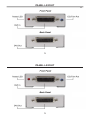
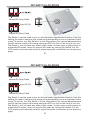
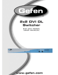
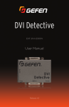
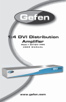
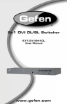
DVI DL Super
Booster Plus
EXT-DVI-141DLBP
User Manual
www.gefen.com
DVI DL Super
Booster Plus
EXT-DVI-141DLBP
User Manual
www.gefen.com
ASKING FOR ASSISTANCE
Rev A1
Technical Support:
Telephone
(818) 772-9100
(800) 545-6900
Fax
(818) 772-9120
Technical Support Hours:
8:00 AM to 5:00 PM Monday thru Friday.
Write To:
Gefen Inc.
c/o Customer Service
20600 Nordhoff St
Chatsworth, CA 91311
www.gefen.com
[email protected]
Notice
Gefen Inc. reserves the right to make changes in the hardware, packaging and any accompanying
documentation without prior written notice.
DVI DL Super Booster Plus is a trademark of Gefen Inc.
© 2009 Gefen Inc., All Rights Reserved
All trademarks are the property of their respective companies
CONTENTS
1
Introduction
2
Features
3
Panel Layout
4
Connecting And Operating The DVI DL Super Booster Plus
5
Dip Switch Location
6
Specifications
7
Warranty
CONTENTS
1
Introduction
2
Features
3
Panel Layout
4
Connecting And Operating The DVI DL Super Booster Plus
5
Dip Switch Location
6
Specifications
7
Warranty
INTRODUCTION
Congratulations on your purchase of the DVI DL Super Booster Plus. Your complete satisfaction is very
important to us.
Gefen
Gefen delivers innovative, progressive computer and electronics add-on solutions that harness
integration, extension, distribution and conversion technologies. Gefen’s reliable, plug-and-play products
supplement cross-platform computer systems, professional audio/video environments and HDTV
systems of all sizes with hard-working solutions that are easy to implement and simple to operate.
The Gefen DVI DL Super Booster Plus
The DVI DL Booster Plus uses a plug-in power supply which helps to extend sparkling clear video images to great distances (up to 200 feet at 2560x1600). Rest assured that with this product you can enjoy
your computer desktop as if the computer was in the same room as the display.
To go beyond the limited inherent DVI distance or if you’d like to use two or more cables, our Boosters
are a perfect option. They replicate digital video signals, enabling you to “daisy chain” cables and Boosters as far as you need to go.
How It Works
This plug and play installation takes mere seconds. Simply place the DVI-DL Super Booster Plus in
the middle of two Dual-Link cables or at the end of a long DVI-DL cable extension. Make sure all video
cables are connected properly at the source and destination ends. Attach the power cable to the DVI-DL
Super Booster Plus. Power up (or restart) all equipment.
1
FEATURES
Features
•
Perfects video sent over long stretches of Dual-Link DVI cables
•
Extends DVI Dual Link displays away up to 200 feet
•
Supports resolutions up to 3840x2400 @ 60 Hz
•
Supports DDWG standards for DVI compliant monitors
•
DDC Signal is amplified for better robustness when interfacing
•
HDCP compliant
Package Includes
(1) DVI DL Super Booster Plus
(1) 5V DC Power Suppy
(1) User’s Manual
2
PANEL LAYOUT
3
PANEL LAYOUT
3
CONNECTING AND OPERATING THE DVI DL SUPER BOOSTER PLUS
How to Connect the DVI DL Super Booster Plus
1.
Connect the long DVI cable from the source into the “DVI In” on the front of the DVI DL Super
Booster Plus. The DVI DL Super Booster Plus is placed next to your display to regenerate the DVI
signal.
2.
Connect a short DVI cable from the “DVI Out” connection in the back of the DVI DL Super Booster
Plus to your display or projector
3.
Plug the 5V DC power supply into the DVI DL Super Booster Plus.
4.
Plug the 5VDC wall mount power supply into the wall outlet.
Manual Equalization
By default, DVI DL Super Booster Plus is set to manual equalization. The service Dip Switch 2, located
on the underside of the unit behind a silver colored metallic sticker, must be in the OFF position for
manual EQ to be enabled. Dip Switch 1 relates to manual EQ short and long cable settings. By default,
Dip Switch 1 is in the long cable mode (OFF). Adjust the EQ Trim Pot on the front of the unit to eliminate
video noise by inserting a small flat-head tool into the Trim Pot port. Turn the Trim Pot in very small
increments to EQ the video signal until all video noise is eliminated. If a short cable is being used and
there is either video noise that cannot be tuned out or no image at all in the long cable mode, change
the manual EQ setting to short cable mode by turning Dip Switch 1 to the ON position. Re-insert the
adjustment tool and EQ the video signal. Use the diagram on the next page to locate and view the
location and settings of the Dip Switches.
4
DIP SWITCH LOCATION
ON
1
2
Manual EQ Long Cable
ON
1
Auto EQ ON
2
Manual EQ Short Cable
Dip Switch 2 can be used to turn on the automatic equalization function. Use this
setting for ease of setup as this mode will automatically tune out unwanted video
noise. To do this, turn Dip Switch 2 to the ON position. No manual adjustments to
the EQ can be made in this mode using the EQ Trim Pot on the front of the unit.
Dip Switch 1 will not have any effect in this mode. If video noise is still present in
automatic EQ mode, return to manual EQ mode by turning Dip Switch 2 to the
OFF position and manually tune the signal using the instructions on the previous
page.
5
SPECIFICATIONS
Video Amplifier Bandwidth .......................................................................................................2 x 165 MHz
Input Video Signal ................................................................................................................... 1.2 Volts p-p
Input DDC Signal .............................................................................................................. 5 volts p-p (TTL)
Maximum Dual Link Range .......................................................................................... 3840 x 2400 x 60hz
DVI Input/Output Connector Type ........................................................................................ DVI-D (29 pin)
Power Consumption .............................................................................................................. 5 Watts (max)
Power Supply…………………….. ..................................................................................................... 5V DC
Dimensions ..................................................................................................................... 2”W x 1”H x 2.5”D
Shipping Weight ................................................................................................................................. 2 Lbs
6