1
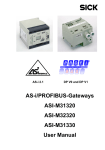
®
PROCESS FIELD BUS
AS-i 2.1
DP V0 and DP V1
AS-i/PROFIBUS Gateways
User Manual
AS-i/PROFIBUS Gateway
Table of Contents
1
The Symbols Used .............................................................................. 7
2
Safety ................................................................................................... 8
2.1
2.2
Intended Use ...................................................................................................... 8
General Safety Information ............................................................................... 8
3
General Information ............................................................................ 9
4
Connections, Displays and Operating Keys of the Gateways
in Stainless Steel Housing ............................................................... 10
4.1
4.3
4.3.1
4.4
4.4.1
4.4.2
Connections of the AS-i/PROFIBUS Gateway Art. No. 566512
(Single Gateway) .............................................................................................. 10
Connections of the AS-i/PROFIBUS Gateway Art. No. 566516
(Double Gateway) ............................................................................................. 12
The PROFIBUS Interface ................................................................................. 13
Bus Termination ................................................................................................. 14
Display and Operating Elements .................................................................... 14
LEDs of the Masters .......................................................................................... 14
Push-Buttons ..................................................................................................... 14
5
Commissioning of the AS-i/PROFIBUS Gateways ......................... 15
5.1
5.1.1
5.1.1.1
5.1.1.2
5.1.1.3
5.1.1.4
5.1.2
5.1.2.1
5.1.2.2
5.1.3
5.1.3.1
5.2
5.2.1
5.2.1.1
5.2.1.2
5.2.1.3
5.2.1.4
5.2.2
5.2.2.1
5.2.2.2
5.2.3
5.2.3.1
AS-i/PROFIBUS Gateway Art. No. 556612 ..................................................... 15
Commissioning .................................................................................................. 15
Fullgraphic Display ............................................................................................. 15
Setting the PROFIBUS DP Address .................................................................. 15
Connecting AS-i Slaves ..................................................................................... 16
Quick Setup ....................................................................................................... 17
Error Tracing ...................................................................................................... 18
Incorrect Slaves ................................................................................................. 18
Error Display (Last Error) ................................................................................... 18
Addressing ......................................................................................................... 19
Programming Slave 2 to Address 6 ................................................................... 19
AS-i/PROFIBUS Gateway Art. No. 556616 ..................................................... 20
Commissioning .................................................................................................. 20
Fullgraphic Display ............................................................................................. 20
Setting the PROFIBUS DP Address .................................................................. 20
Connecting AS-i Slaves ..................................................................................... 21
Quick Setup ....................................................................................................... 22
Error Tracing ...................................................................................................... 23
Incorrect Slaves ................................................................................................. 23
Error Display (Last Error) ................................................................................... 23
Addressing ......................................................................................................... 24
Programming Slave 2 to Address 6 ................................................................... 24
4.2
Subject to reasonable modifications due to technical advances.
2
Copyright Murrelektronik, Printed in Germany
Murrelektronik GmbH · Falkenstr. 3 · D-71570 Oppenweiler · Phone +49 71 91-47-0 · Fax +49 71 91-47-130 · Internet http://www.murrelekronik.com
issue date 17.5.2005
Table of Contents
AS-i/PROFIBUS Gateway
6
Operating by Fullgraphic Display .................................................... 25
6.1
6.1.1
6.1.2
6.2
6.3
6.4
6.5
6.5.1
6.5.2
6.5.3
6.5.4
6.5.5
6.5.6
6.5.7
6.5.8
6.5.9
6.5.10
6.5.11
6.5.12
6.6
6.6.3
6.6.4
6.6.5
6.6.6
6.6.7
6.7
6.7.1
6.7.2
6.7.3
6.7.4
6.7.5
6.7.6
6.8
6.8.1
6.8.2
6.8.3
6.9
6.9.1
6.9.2
6.10
PROFIBUS (Fieldbus Interface) ...................................................................... 27
PROFIBUS Address (PROFIBUS Station Address) .......................................... 27
PROFIBUS Status ............................................................................................. 28
Quick Setup ...................................................................................................... 28
Slave Adr Tool (Slave Addressing Tool) ....................................................... 29
Slave Test Tool ................................................................................................ 30
Setup (Configuration of the AS-i Circuit) ...................................................... 31
AS-i Circuit ......................................................................................................... 31
Setup (Configuration of the AS-i Circuit) ........................................................... 32
AS-i Slave Adr (Set/Change Slave Address) ..................................................... 32
Force Offline ...................................................................................................... 32
Operation Mode ................................................................................................. 33
Store Act Cfg (Store Actual Detected Configuration) ........................................ 33
Permanent Param (Projected Parameter) ......................................................... 33
Permanent Config (Projected Configuration Data) ............................................ 34
AS-i Address Assistant ...................................................................................... 34
LOS (List of Offline Slaves) ............................................................................... 34
Auto Adr Enable (Enable Automatic Address Programming) ............................ 35
Factory Reset .................................................................................................... 35
IO + Param. Test (Testing AS-i In- and Outputs as well as reading and
writing AS-i Parameters) ................................................................................. 36
AS-i Circuit ......................................................................................................... 36
IO + Param. Test (Testing AS-i In- and Outputs as well as reading and
writing AS-i Parameters) .................................................................................... 36
Binary Input ....................................................................................................... 37
Binary Outputs ................................................................................................... 37
Analog Inputs ..................................................................................................... 37
Analog Outputs .................................................................................................. 38
Parameter .......................................................................................................... 38
Diagnosis (Normal AS-i Diagnosis) ............................................................... 39
AS-i Circuit ......................................................................................................... 39
Diagnosis (Normal AS-i Diagnosis) ................................................................... 39
Flags .................................................................................................................. 40
Actual Config (Actual Configuration) ................................................................. 41
LPF (List of Periphery Faults) ............................................................................ 42
AS-i Master (Info) .............................................................................................. 42
Adv. Diagnosis (Advanced AS-i Diagnosis) .................................................. 42
Error Counters ................................................................................................... 43
LCS (List of Slaves having caused a Configuration Error) ................................ 43
Fault Detector .................................................................................................... 43
AS-i Safety ........................................................................................................ 44
Safety Slaves ..................................................................................................... 44
Safety Monitor ................................................................................................... 45
Language .......................................................................................................... 45
7
Advanced Diagnostics for AS-i Masters ......................................... 46
7.1
7.2
List of Corrupted AS-i Slaves (LCS) .............................................................. 46
Protocol Analysis: Counters of Corrupted Data Telegrams ........................ 46
6.6.1
6.6.2
issue date 17.5.2005
Table of Contents
Subject to reasonable modifications due to technical advances.
Copyright Murrelektronik, Printed in Germany
Murrelektronik GmbH · Falkenstr. 3 · D-71570 Oppenweiler · Phone +49 71 91-47-0 · Fax +49 71 91-47-130 · Internet http://www.murrelekronik.com
3
AS-i/PROFIBUS Gateway
Table of Contents
7.3
7.4
7.4.1
7.4.2
7.4.3
7.4.4
Offline Phase on Configuration Errors (LOS) ............................................... 47
Functions of the AS-i Fault Detector .............................................................. 47
Recognition of Duplicate Addresses .................................................................. 47
Earth Fault Detector ........................................................................................... 48
Noise Detector ................................................................................................... 48
Overvoltage Detector ......................................................................................... 48
8
PROFIBUS DP .................................................................................... 49
8.1
8.1.1
8.1.1.1
8.1.2
8.1.2.1
8.1.3
8.1.3.1
8.1.3.2
8.1.3.3
8.2
8.3
DP Telegrams ................................................................................................... 49
Diagnosis ........................................................................................................... 49
Parameters ........................................................................................................ 52
Configuration DP V0 (cyclic data) ...................................................................... 54
AS-i-V2.1 Mode .................................................................................................. 54
I/O Data ............................................................................................................. 56
Process data ...................................................................................................... 56
Analog data ........................................................................................................ 57
Command Interface ........................................................................................... 58
DP V1 ................................................................................................................ 58
Restrictions ...................................................................................................... 59
9
Command Interface ........................................................................... 60
Construction ..................................................................................................... 60
List of all Commands ......................................................................................... 61
Values for Results .............................................................................................. 63
Commands of the Command Interface .......................................................... 63
Analog Data ....................................................................................................... 63
Overview of the Commands ............................................................................... 63
Read 1 7.3-Slave in.Data (RD_7X_IN) .............................................................. 64
Write 1 7.3-Slave out.Data (WR_7X_OUT) ....................................................... 64
Read 1 7.3-Slave out.Data (RD_7X_OUT) ........................................................ 65
Read 4 7.3-Slave in.Data (RD_7X_IN_X) .......................................................... 65
Write 4 7.3-Slave out.Data (WR_7X_OUT_X) ................................................... 66
Read 4 7.3-Slave out.Data (RD_7X_OUT_X) .................................................... 66
WR_74_PARAM ................................................................................................ 66
RD_74_PARAM ................................................................................................. 67
RD_74_ID .......................................................................................................... 68
RD_74_DIAG ..................................................................................................... 68
Diagnosis Data ................................................................................................... 69
Overview of the Commands ............................................................................... 69
Get Lists and Flags (Get_LPS, Get_LAS, Get_LDS, Get_Flags)
(GET_LISTS) ..................................................................................................... 69
9.2.2.3
Get Flags (GET_FLAGS) ................................................................................... 71
9.2.2.4
Get Delta List (GET_DELTA) ............................................................................. 72
9.2.2.5
Get List of Corrupted Slaves (GET_LCS) .......................................................... 73
9.2.2.6
Get List of Activated Slaves (GET_LAS) ........................................................... 73
9.2.2.7
Get List of Detected AS-i slaves (GET_LDS) .................................................... 74
9.2.2.8
Get list of peripheral faults (GET_LPF) .............................................................. 74
9.2.2.9
Get List of Offline Slaves (GET_LOS) ............................................................... 75
9.2.2.10 Set List of Off-line Slaves (SET_LOS) ............................................................... 76
Subject to reasonable modifications due to technical advances.
4
Copyright Murrelektronik, Printed in Germany
Murrelektronik GmbH · Falkenstr. 3 · D-71570 Oppenweiler · Phone +49 71 91-47-0 · Fax +49 71 91-47-130 · Internet http://www.murrelekronik.com
issue date 17.5.2005
9.1
9.1.1
9.1.2
9.2
9.2.1
9.2.1.1
9.2.1.2
9.2.1.3
9.2.1.4
9.2.1.5
9.2.1.6
9.2.1.7
9.2.1.8
9.2.1.9
9.2.1.10
9.2.1.11
9.2.2
9.2.2.1
9.2.2.2
issue date 17.5.2005
AS-i/PROFIBUS Gateway
Table of Contents
9.2.2.11
9.2.2.12
9.2.2.13
9.2.2.14
9.2.2.15
9.2.2.16
9.2.3
9.2.3.1
9.2.3.2
9.2.3.3
9.2.3.4
9.2.4
9.2.4.1
9.2.4.2
9.2.4.3
9.2.4.4
9.2.4.5
9.2.4.6
9.2.4.7
9.2.4.8
9.2.4.9
9.2.4.10
9.2.4.11
9.2.4.12
9.2.4.13
9.2.4.14
9.2.5
9.2.5.1
9.2.5.2
9.2.5.3
9.2.5.4
9.2.5.5
9.2.5.6
9.2.5.7
9.2.5.8
9.2.5.9
9.2.5.10
9.2.5.11
9.2.5.12
9.2.5.13
9.2.5.14
9.2.5.15
9.3
9.3.1
9.3.2
9.3.3
Get transm.err.counters (GET_TECA) .............................................................. 77
Get transm.err.counters (GET_TECB) .............................................................. 77
GET_TEC_X ...................................................................................................... 78
Read Fault Detector (READ_FAULT_DETECTOR) .......................................... 79
Read List of Duplicate Addresses (READ_DUPLICATE_ADDR) ...................... 79
Functional profiles ............................................................................................. 80
Functional profiles ............................................................................................. 80
"Safety at Work" List 1 ....................................................................................... 80
"Safety at Work" Monitor Diagnosis ................................................................... 82
Integrated AS-i Sensors: Warnings ................................................................... 84
Integrated AS-i Sensors: Availability ................................................................. 85
Configuration of the AS-i Master ....................................................................... 86
Overview of the Commands .............................................................................. 86
Set Operation Mode (SET_OP_MODE: Set_Operation_Mode) ........................ 86
Store Actual Configuration (STORE_CDI) ......................................................... 87
Read Actual Configuration (READ_CDI) ........................................................... 88
Set Permanent Configuration (SET_PCD) ........................................................ 88
Get Extended Permanent Configuration (GET_PCD) ....................................... 89
Set List of Projected Slaves (SET_LPS) ........................................................... 90
Get List of Projected Slaves (GET_LPS) ........................................................... 90
Store Actual Parameters (STORE_PI) .............................................................. 91
Write Parameter (WRITE_P) ............................................................................. 92
Read Parameter (READ_PI: Read_Parameter) ................................................ 92
Set_Permanent_Parameter (SET_PP) .............................................................. 93
Get_Permanent_Parameter (GET_PP) ............................................................. 93
Set Auto Address Enable (SET_AAE) ............................................................... 94
Other Commands .............................................................................................. 94
Overview of the Commands .............................................................................. 94
IDLE ................................................................................................................... 94
Read Input Data Image (READ_IDI) ................................................................. 95
Write Output Data Image (WRITE_ODI) ........................................................... 96
Read Output Data Image (READ_ODI) ............................................................. 96
Change Slave Address (SLAVE_ADDR) ........................................................... 96
Write AS-i Slave Extended ID1 (WRITE_XID1) ................................................. 97
Set Offline Mode (SET_OFFLINE) .................................................................... 98
Release Data Exchange (SET_DATA_EX) ....................................................... 99
BUTTONS ......................................................................................................... 99
FP_PARAM ....................................................................................................... 99
FP_DATA ........................................................................................................ 100
EXT_DIAG ....................................................................................................... 100
RD_EXT_DIAG ................................................................................................ 101
INVERTER ...................................................................................................... 102
Command Interface Examples ..................................................................... 102
Reading analog Input Values .......................................................................... 102
Store current Configuration to the AS-i Master ................................................ 104
Store new Configuration for all Slaves ............................................................ 108
10
Commissioning Tools and Accessories ....................................... 116
10.1
Windows Software AS-i Control Tools ........................................................ 116
Subject to reasonable modifications due to technical advances.
Copyright Murrelektronik, Printed in Germany
Murrelektronik GmbH · Falkenstr. 3 · D-71570 Oppenweiler · Phone +49 71 91-47-0 · Fax +49 71 91-47-130 · Internet http://www.murrelekronik.com
5
AS-i/PROFIBUS Gateway
Table of Contents
10.2
PROFIBUS DP Master Simulator .................................................................. 119
11
Appendix: Codes indicated by the Display ................................... 120
12
Appendix: Installation/Commissioning Instructions ................... 122
12.1
Installation/Commissioning Instruction AS-i/PROFIBUS Gateway
Article Number 556612 .................................................................................. 122
Installation/Commissioning Instruction AS-i/PROFIBUS Gateway
Article Number 556616 .................................................................................. 131
12.2
Glossary: AS-Interface Terms ........................................................ 140
issue date 17.5.2005
13
Subject to reasonable modifications due to technical advances.
6
Copyright Murrelektronik, Printed in Germany
Murrelektronik GmbH · Falkenstr. 3 · D-71570 Oppenweiler · Phone +49 71 91-47-0 · Fax +49 71 91-47-130 · Internet http://www.murrelekronik.com
AS-i/PROFIBUS Gateway
1
The Symbols Used
The Symbols Used
This symbol warns the user of possible danger. Not following this
warning can lead to personal injury or death and/or destruction of
the equipment.
This symbol warns the user of a possible failure. Not following this
warning can lead to total failure of the device or any other connected
equipment.
issue date 17.5.2005
This symbol draws the user's attention to important information.
Subject to reasonable modifications due to technical advances.
Copyright Murrelektronik, Printed in Germany
Murrelektronik GmbH · Falkenstr. 3 · D-71570 Oppenweiler · Phone +49 71 91-47-0 · Fax +49 71 91-47-130 · Internet http://www.murrelekronik.com
7
AS-i/PROFIBUS Gateway
Safety
2
Safety
2.1
Intended Use
The protection of operating personnel and the system against possible danger is not guaranteed if the control interface unit is not operated in accordance with its intended use.
The device may only be operated by appropriately qualified personnel in accordance with this operating manual.
2.2
General Safety Information
Safety and correct functioning of the device cannot be guaranteed if
any operation other than that described in this operation manual is
performed.
Connecting the equipment and any maintenance work to be carried
out with voltage applied to the equipment must exclusively be performed by appropriately qualified electrotechnical personnel.
In case a failure cannot be repaired, the device must be taken out of
operation and kept from inadvertently being put back into operation.
Repair work is to be carried out by the manufacturer only. Additions
or modifications to the equipment are not allowed and will void the
warranty.
issue date 17.5.2005
The operator is responsible for the observance of local safety standards.
Subject to reasonable modifications due to technical advances.
8
Copyright Murrelektronik, Printed in Germany
Murrelektronik GmbH · Falkenstr. 3 · D-71570 Oppenweiler · Phone +49 71 91-47-0 · Fax +49 71 91-47-130 · Internet http://www.murrelekronik.com
AS-i/PROFIBUS Gateway
3
General Information
General Information
This operating instruction holds for the following devices of the Murrelektronik
GmbH:
• AS-i/PROFIBUS gateway in stainless steel housing - 1 master
Article No. 556612
• AS-i/PROFIBUS gateway in stainless steel housing - 2 master
Article No. 556616
The AS-i/PROFIBUS gateways already fulfill to connect AS-Interface systems to
the PROFIBUS. They act as a master for the AS-Interface and as a slave for the
PROFIBUS.
New AS-i Specification 2.1
The AS-i/PROFIBUS gateways already fulfil the new AS-i Specification 2.1. This
means:
• Up to 62 AS-Interface slaves can be connected per AS-i network
• The transfer of analog signals via AS-i is integrated in the masters
• All further functions of the new specification, e.g. the diagnosis of the AS-i peripheral fault, are implemented.
All AS-i functions are provided as well cyclically as acyclically via PROFIBUS
DP V1.
In the cyclic data transfer optionally up to 32 bytes I/O data are beeing transferred
for the binary data of one AS-i network. Aditionally, analog signals and all further
commands of the new AS-i specification can be transferred in the management
channel via PROFIBUS.
Advanced Diagnostics
Diagnostics, which go far beyond the standard diagnostics, facilitate the simple
detection of occassionally occuring configuration errors and further irritations influencing the AS-i communication. In case of an error, the down time of machines
can be minimized or preventive maintenance can be initiated.
Commissioning and monitoring
The AS-i/PROFIBUS gateways can be commissioned or programmed with the
help of the software "AS-i Control Tools" in combination with the PROFIBUS DP
master simulator. The GSD file is included in the package.
Commissioning, debugging and setting up the AS-i parameters without the software can only be accomplished by directly using the system's push-buttons, the
display and the LEDs.
Accessories:
Software "AS-i Control Tools" (Article no. 55717)
issue date 17.5.2005
PROFIBUS DP master simulator (Article no. 556617)
PS2/Sub-D data cable for AS-i Control Tools (Part Nr. 556617)
Subject to reasonable modifications due to technical advances.
Copyright Murrelektronik, Printed in Germany
Murrelektronik GmbH · Falkenstr. 3 · D-71570 Oppenweiler · Phone +49 71 91-47-0 · Fax +49 71 91-47-130 · Internet http://www.murrelekronik.com
9
AS-i/PROFIBUS Gateway
4
Connections, Displays and Operating Keys of the Gateways in
Connections, Displays and Operating Keys of the Gateways
in Stainless Steel Housing
Devices in stainless steel housing:
On the front panel of the device in stainless steel housing are located:
• Terminals to connect the power supply and the AS-i circuit
• A 9 pin SUB-D connector as PROFIBUS interface
• 7 LEDs
• A LC display
• 4 push-buttons to configure the device
Connections of the AS-i/PROFIBUS Gateway Art. No. 566512
(Single Gateway)
issue date 17.5.2005
4.1
Subject to reasonable modifications due to technical advances.
10
Copyright Murrelektronik, Printed in Germany
Murrelektronik GmbH · Falkenstr. 3 · D-71570 Oppenweiler · Phone +49 71 91-47-0 · Fax +49 71 91-47-130 · Internet http://www.murrelekronik.com
AS-i/PROFIBUS Gateway
Connections, Displays and Operating Keys of the Gateways in
It is not allowed to connect slaves or repeaters to the hatched
marked cable.
It is not allowed to connect AS-i power supplies or another master to
the yellow marked cable.
issue date 17.5.2005
The function ground can be connected either at the ground screw or
at the terminal.
The function ground should be connected with a cable as short as
possible to guarantee a good EMC property.
Therefore is to prefer to connect the ground via the ground screw.
Subject to reasonable modifications due to technical advances.
Copyright Murrelektronik, Printed in Germany
Murrelektronik GmbH · Falkenstr. 3 · D-71570 Oppenweiler · Phone +49 71 91-47-0 · Fax +49 71 91-47-130 · Internet http://www.murrelekronik.com
11
AS-i/PROFIBUS Gateway
4.2
Connections, Displays and Operating Keys of the Gateways in
Connections of the AS-i/PROFIBUS Gateway Art. No. 566516
(Double Gateway)
AS-i circuit 1 and 2 are powered by seperate power supplies.
It is not allowed to connect slaves or repeaters to the hatched
marked cable.
issue date 17.5.2005
It is not allowed to connect AS-i power supplies or another master to
the yellow marked cable.
Subject to reasonable modifications due to technical advances.
12
Copyright Murrelektronik, Printed in Germany
Murrelektronik GmbH · Falkenstr. 3 · D-71570 Oppenweiler · Phone +49 71 91-47-0 · Fax +49 71 91-47-130 · Internet http://www.murrelekronik.com
AS-i/PROFIBUS Gateway
Connections, Displays and Operating Keys of the Gateways in
The function ground can be connected either at the ground screw or
at the terminal.
The function ground should be connected with a cable as short as
possible to guarantee a good EMC property.
Therefore is to prefer to connect the ground via the ground screw.
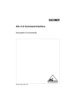
4.3
The PROFIBUS Interface
The PROFIBUS interface is realized as a 9-pin SUB-D connector, in accordance
to the standard for PROFIBUS DIN 19245. It is placed on the right hand side of the
front panel.
9
8
7
6
5
4
3
2
1
RxD/TxD-N
(data line A)
RxD/TxD-P
(data line B)
PROFIBUS
The AS-i/PROFIBUS gateway sends and receives on pins 3 and 8 of the SUB-D
socket. The PROFIBUS signal “RxD/TxD-N (data line A)1” is located on pin 8, the
signal “RxD/TxD-P (data line B)1” is located on pin 3.
issue date 17.5.2005
The pins 5 (0 V) and 6 (5 V) supply 5 V DC for the bus termination.
1. If you measure the DC voltage between RxD/TxD-P (data line B) and RxD/TxD-N (data line A), RxD/TxD-P (data line B) is the positive pole
when the bus is silent.
Subject to reasonable modifications due to technical advances.
Copyright Murrelektronik, Printed in Germany
Murrelektronik GmbH · Falkenstr. 3 · D-71570 Oppenweiler · Phone +49 71 91-47-0 · Fax +49 71 91-47-130 · Internet http://www.murrelekronik.com
13
AS-i/PROFIBUS Gateway
4.3.1
Connections, Displays and Operating Keys of the Gateways in
Bus Termination
If the AS-i/PROFIBUS gateway is at the end of the PROFIBUS line, the termination
resistors in the PROFIBUS connector have to be switched on.
4.4
4.4.1
Display and Operating Elements
LEDs of the Masters
On the front panel of the AS-i/PROFIBUS gateways there are seven light-emitting
diodes. The meaning of them are as follow:
4.4.2
Power
The master's power supply is sufficient.
Profibus
LED on: Gateway is allocated to a PROFIBUS master.
LED off: Gateway is not allocated to a PROFIBUS master.
Config err
Configuration error:
At least one configured slave is missing, at least one detected
slave is not projected or for at least one projected and detected
slave the actual configuration data does not match the nominal
configuration data.
This LED flashes if there is at least one periphery fault at one AS-i
slave in the AS-i network. If there are configuration errors as well
as periphery faults, only configuration error is displayed.
U AS-i
The AS-i circuit is sufficiently powered.
AS-i active
Normal operation active.
(Flashes, if a B slave is displayed)
prg enable
Automatic address programming enabled.
Exactly one slave is missing in protected operating mode. The
slave can be replaced by another slave of the same type with address zero. The master addresses the new slave to the faulty address and thus eliminates the configuration error.
prj mode
The AS-i master is in configuration mode.
Push-Buttons
The push-buttons cause the following:
Mode/⇑
Switching between configuration mode and protected operating
mode and saving the current AS-i configuration as the nominal
configuration.
Set/⇓
Selecting and assigning the address to a slave.
OK, ESC
Changing to graphical mode (see chapter 5).
issue date 17.5.2005
The detailed operation is described in chapter 5f.
Subject to reasonable modifications due to technical advances.
14
Copyright Murrelektronik, Printed in Germany
Murrelektronik GmbH · Falkenstr. 3 · D-71570 Oppenweiler · Phone +49 71 91-47-0 · Fax +49 71 91-47-130 · Internet http://www.murrelekronik.com
AS-i/PROFIBUS Gateway
Commissioning of the AS-i/PROFIBUS Gateways
5
Commissioning of the AS-i/PROFIBUS Gateways
5.1
AS-i/PROFIBUS Gateway Art. No. 556612
5.1.1
Commissioning
5.1.1.1
Fullgraphic Display
OK
LCD
1.12A
PROFIBUS
QUICK SETUP
SETUP
IO + PARAM. TEST
UNKNOWN SLAVE
klassische Anzeige
classical display
affichage classique
indicazione classico
indicación clásico
LCD
vollgrafische Anzeige
fullgraphical display
affichage graphique
indicazione grafico
indicación gráfico
ESC
Aufbau siehe Zusatzblatt
structure see additional page
structure voir page supplémentaire
struttura vede pagina supplementare
estructura considera página adicional
5.1.1.2
Setting the PROFIBUS DP Address
OK
OK
LCD
LCD
PROFIBUS
QUICK SETUP
SETUP
PROFIBUS ADDRESS
OLD ADDRESS
3
NEW ADDRESS 000
2x ↓
OK
LCD
LCD
issue date 17.5.2005
PROFIBUS ADDRESS
PROFIBUS STATUS
PROFIBUS ADDRESS
OLD ADDRESS
3
NEW ADDRESS 000
Subject to reasonable modifications due to technical advances.
Copyright Murrelektronik, Printed in Germany
Murrelektronik GmbH · Falkenstr. 3 · D-71570 Oppenweiler · Phone +49 71 91-47-0 · Fax +49 71 91-47-130 · Internet http://www.murrelekronik.com
15
AS-i/PROFIBUS Gateway
Commissioning of the AS-i/PROFIBUS Gateways
↑
2x OK
OK
LCD
PROFIBUS ADDRESS
OLD ADDRESS
14
NEW ADDRESS 000
PROFIBUS ADDRESS
OLD ADDRESS
3
NEW ADDRESS 010
LCD
2x ESC
4x ↑
LCD
OK
PROFIBUS
QUICK SETUP
SETUP
2x ESC
Das Gerät ist werkseitig auf Adresse 3 eingestellt.
The device is set to address 3 at the factory.
L’appareil est réglé en usine à l’adresse 3.
Il dispositivo viene de la fábrica con l’indirizzo 3.
El aparato viene ajustado de fábrica en la dirección 3.
Connecting AS-i Slaves
Config error
U AS-i
AS-i active
prg enable
prj mode
AS-Interface
AS-Interface
Slave 1
AS-Interface
Slave 5
Profibus
Config error
U AS-i
AS-i active
prg enable
prj mode
AS-Interface
LCD
1. 41
SEARCHING SLAVES
AS-Interface
Slave 24
Subject to reasonable modifications due to technical advances.
16
LCD
Power
AS-Interface
Master
Profibus
AS-Interface
Slave 1
AS-Interface
Slave 5
1. 1
0.5s
1. 5
0.5s
1.24
AS-Interface
Slave 24
0.5s
Copyright Murrelektronik, Printed in Germany
Murrelektronik GmbH · Falkenstr. 3 · D-71570 Oppenweiler · Phone +49 71 91-47-0 · Fax +49 71 91-47-130 · Internet http://www.murrelekronik.com
issue date 17.5.2005
Power
AS-Interface
Master
5.1.1.3
AS-i/PROFIBUS Gateway
5.1.1.4
Commissioning of the AS-i/PROFIBUS Gateways
Quick Setup
OK
config error
LCD
1. 5
LCD
STORE AS-INTERFACE
CONFIGURATION
OK
STORE +PRJ MODE
↓
OK
2x ESC
LCD
config error
PROFIBUS
QUICK SETUP
SETUP
IO + PARAM. TEST
LCD
1.
OK
CONFIGURATION OK
LCD
WARNING:
OUTPUTS MAY BE
RESET
OK
LCD
PROFIBUS ERROR
NO CONNECTION
↓
LCD
issue date 17.5.2005
STORE AS-I
CONFIGURATION
STORE +RUN
STORE +PRJ MODE
Subject to reasonable modifications due to technical advances.
Copyright Murrelektronik, Printed in Germany
Murrelektronik GmbH · Falkenstr. 3 · D-71570 Oppenweiler · Phone +49 71 91-47-0 · Fax +49 71 91-47-130 · Internet http://www.murrelekronik.com
17
AS-i/PROFIBUS Gateway
5.1.2
Commissioning of the AS-i/PROFIBUS Gateways
Error Tracing
5.1.2.1
Incorrect Slaves
Power
Config error
U AS-i
AS-i active
prg enable
prj mode
AS-Interface
LCD
AS-Interface
Master
Profibus
1.1
MISSING SLAVE
2.0s
AS-Interface
Slave 1
LCD
1.24
AS-Interface
Slave 5
MISSING SLAVE
AS-Interface
Slave 24
Error Display (Last Error)
Profibus
Config error
U AS-i
AS-i active
prg enable
prj mode
AS-Interface
Power
AS-Interface
Master
Power
Profibus
Config error
U AS-i
AS-i active
prg enable
prj mode
AS-Interface
AS-Interface
Slave 1
AS-Interface
Slave 1
AS-Interface
Slave 5
AS-Interface
Slave 5
AS-Interface
Master
5.1.2.2
2.0s
LCD
PROFIBUS ERROR
NO CONNECTION
set/↓
24
AS-Interface
Slave 24
issue date 17.5.2005
AS-Interface
Slave 24
Subject to reasonable modifications due to technical advances.
18
Copyright Murrelektronik, Printed in Germany
Murrelektronik GmbH · Falkenstr. 3 · D-71570 Oppenweiler · Phone +49 71 91-47-0 · Fax +49 71 91-47-130 · Internet http://www.murrelekronik.com
AS-i/PROFIBUS Gateway
Commissioning of the AS-i/PROFIBUS Gateways
5.1.3
Addressing
5.1.3.1
Programming Slave 2 to Address 6
LCD
1. 41
1x ↓
3xOK
SEARCHING SLAVE
SLAVE ADR TOOL
OLD ADDRESS 2
NEW ADDRESS 6
PRG
2x ↓
OK
LCD
PROFIBUS
QUICK SETUP
SLAVE ADR TOOL
SLAVE TEST TOOL
1x ↓
SLAVE ADR TOOL
OLD ADDRESS 2
NEW ADDRESS 6
PRG
OK
LCD
LCD
OK
LCD
SLAVE ADR TOOL
CONNECT NEW SLAVE
OLD ADDRESS
NEW ADDRESS
Master
SLAVE ADR TOOL
LCD
OK
Slave
Modul anschließen/Connect
module/Reliez module/Colleghi
modulo/Conecte modulo
LCD
1. 6
LCD
UNKNOWN SLAVE
issue date 17.5.2005
SLAVE ADR TOOL
OLD ADDRESS 2
NEW ADDRESS 3
PRG
2x ESC
Subject to reasonable modifications due to technical advances.
Copyright Murrelektronik, Printed in Germany
Murrelektronik GmbH · Falkenstr. 3 · D-71570 Oppenweiler · Phone +49 71 91-47-0 · Fax +49 71 91-47-130 · Internet http://www.murrelekronik.com
19
AS-i/PROFIBUS Gateway
Commissioning of the AS-i/PROFIBUS Gateways
5.2
AS-i/PROFIBUS Gateway Art. No. 556616
5.2.1
Commissioning
5.2.1.1
Fullgraphic Display
OK
LCD
1.12A
PROFIBUS
QUICK SETUP
SETUP
IO + PARAM. TEST
UNKNOWN SLAVE
klassische Anzeige
classical display
affichage classique
indicazione classico
indicación clásico
LCD
vollgrafische Anzeige
fullgraphical display
affichage graphique
indicazione grafico
indicación gráfico
ESC
Aufbau siehe Zusatzblatt
structure see additional page
structure voir page supplémentaire
struttura vede pagina supplementare
estructura considera página adicional
5.2.1.2
Setting the PROFIBUS DP Address
OK
OK
LCD
LCD
PROFIBUS
QUICK SETUP
SETUP
PROFIBUS ADDRESS
OLD ADDRESS
3
NEW ADDRESS 000
2x ↓
OK
LCD
LCD
PROFIBUS ADDRESS
OLD ADDRESS
3
NEW ADDRESS 000
issue date 17.5.2005
PROFIBUS ADDRESS
PROFIBUS STATUS
Subject to reasonable modifications due to technical advances.
20
Copyright Murrelektronik, Printed in Germany
Murrelektronik GmbH · Falkenstr. 3 · D-71570 Oppenweiler · Phone +49 71 91-47-0 · Fax +49 71 91-47-130 · Internet http://www.murrelekronik.com
AS-i/PROFIBUS Gateway
Commissioning of the AS-i/PROFIBUS Gateways
↑
2x OK
OK
LCD
PROFIBUS ADDRESS
OLD ADDRESS
14
NEW ADDRESS 000
PROFIBUS ADDRESS
OLD ADDRESS
3
NEW ADDRESS 010
LCD
2x ESC
4x ↑
LCD
OK
PROFIBUS
QUICK SETUP
SETUP
2x ESC
Das Gerät ist werkseitig auf Adresse 3 eingestellt.
The device is set to address 3 at the factory.
L’appareil est réglé en usine à l’adresse 3.
Il dispositivo viene de la fábrica con l’indirizzo 3.
El aparato viene ajustado de fábrica en la dirección 3.
Connecting AS-i Slaves
Power
Config error
U AS-i
AS-i active
prg enable
prj mode
AS-Interface
AS-Interface
Slave 1
Profibus
Config error
U AS-i
AS-i active
prg enable
LCD
1. 41
prj mode
AS-Interface
AS-Interface
Slave 1
1. 1
0.5s
1. 5
SEARCHING SLAVES
AS-Interface
Slave 5
LCD
2. 41
issue date 17.5.2005
LCD
Power
AS-Interface
Master
Profibus
AS-Interface
Master
5.2.1.3
SEARCHING SLAVES
Subject to reasonable modifications due to technical advances.
AS-Interface
Slave 5
0.5s
2. 41
SEARCHING SLAVES
0.5s
Copyright Murrelektronik, Printed in Germany
Murrelektronik GmbH · Falkenstr. 3 · D-71570 Oppenweiler · Phone +49 71 91-47-0 · Fax +49 71 91-47-130 · Internet http://www.murrelekronik.com
21
AS-i/PROFIBUS Gateway
5.2.1.4
Commissioning of the AS-i/PROFIBUS Gateways
Quick Setup
OK
config error
LCD
1. 5
LCD
STORE AS-INTERFACE
CONFIGURATION
OK
STORE +PRJ MODE
↓
OK
2x ESC
LCD
config error
PROFIBUS
QUICK SETUP
SETUP
IO + PARAM. TEST
LCD
1.
OK
CONFIGURATION OK
LCD
WARNING:
OUTPUTS MAY BE
RESET
OK
LCD
PROFIBUS ERROR
NO CONNECTION
↓
LCD
issue date 17.5.2005
STORE AS-I
CONFIGURATION
STORE +RUN
STORE +PRJ MODE
Subject to reasonable modifications due to technical advances.
22
Copyright Murrelektronik, Printed in Germany
Murrelektronik GmbH · Falkenstr. 3 · D-71570 Oppenweiler · Phone +49 71 91-47-0 · Fax +49 71 91-47-130 · Internet http://www.murrelekronik.com
AS-i/PROFIBUS Gateway
5.2.2
Commissioning of the AS-i/PROFIBUS Gateways
Error Tracing
5.2.2.1
Incorrect Slaves
Power
Config error
U AS-i
AS-i active
prg enable
prj mode
AS-Interface
LCD
AS-Interface
Master
Profibus
1.1
MISSING SLAVE
2.0s
AS-Interface
Slave 1
LCD
1.24
AS-Interface
Slave 5
MISSING SLAVE
AS-Interface
Slave 24
Error Display (Last Error)
Profibus
Config error
U AS-i
AS-i active
prg enable
prj mode
AS-Interface
Power
AS-Interface
Master
Power
Profibus
Config error
U AS-i
AS-i active
prg enable
prj mode
AS-Interface
AS-Interface
Slave 1
AS-Interface
Slave 1
AS-Interface
Slave 5
AS-Interface
Slave 5
AS-Interface
Master
5.2.2.2
2.0s
LCD
PROFIBUS ERROR
NO CONNECTION
set/↓
24
AS-Interface
Slave 24
issue date 17.5.2005
AS-Interface
Slave 24
Subject to reasonable modifications due to technical advances.
Copyright Murrelektronik, Printed in Germany
Murrelektronik GmbH · Falkenstr. 3 · D-71570 Oppenweiler · Phone +49 71 91-47-0 · Fax +49 71 91-47-130 · Internet http://www.murrelekronik.com
23
AS-i/PROFIBUS Gateway
Commissioning of the AS-i/PROFIBUS Gateways
5.2.3
Addressing
5.2.3.1
Programming Slave 2 to Address 6
LCD
1. 41
1x ↓
3xOK
SEARCHING SLAVE
SLAVE ADR TOOL
OLD ADDRESS 2
NEW ADDRESS 6
PRG
2x ↓
OK
LCD
PROFIBUS
QUICK SETUP
SLAVE ADR TOOL
SLAVE TEST TOOL
1x ↓
SLAVE ADR TOOL
OLD ADDRESS 2
NEW ADDRESS 6
PRG
OK
LCD
LCD
OK
LCD
SLAVE ADR TOOL
CONNECT NEW SLAVE
OLD ADDRESS
NEW ADDRESS
Master
SLAVE ADR TOOL
LCD
OK
Slave
Modul anschließen/Connect
module/Reliez module/Colleghi
modulo/Conecte modulo
LCD
LCD
1. 6
UNKNOWN SLAVE
issue date 17.5.2005
SLAVE ADR TOOL
OLD ADDRESS 2
NEW ADDRESS 3
PRG
2x ESC
Subject to reasonable modifications due to technical advances.
24
Copyright Murrelektronik, Printed in Germany
Murrelektronik GmbH · Falkenstr. 3 · D-71570 Oppenweiler · Phone +49 71 91-47-0 · Fax +49 71 91-47-130 · Internet http://www.murrelekronik.com
AS-i/PROFIBUS Gateway
6
Operating by Fullgraphic Display
Operating by Fullgraphic Display
Inbetriebnahme/Commissioning
Traditioneller Modus
Traditional Mode
1.12A
grün markierte Werte sind editierbar
green marked data can be edited
AS-I CIRCUIT 1
AS-I CIRCUIT 2
Erweiterter Display Modus
Advanced Display Mode
SETUP
AS-I SLAVE ADDR
FORCE OFFLINE
OPERATION MODE
STORE ACT CFG
PERMANENT PARAM
PERMANENT CFG
ADDR.ASSISTANT
LOS
AUTO ADR ENABLE
FACTORY RESET
PROFIBUS
PROFIBUS ADDRESS
PROFIBUS STATUS
PROFIBUS ADDRESS
OLD ADDRESS 099
NEW ADDRESS 003
AS-I CIRCUIT 1
AS-I CIRCUIT 2
PROFIBUS STATUS
DPV0: CONN.
DPV1: CONN.
WARNING:
OUTPUTS MAY BE
SET AND HOST MAY
LOOSE CONTROL.
ENGLISH
DEUTSCH
FRANCAIS
ITALIANO
ESPAGNOL
AS-I SLAVE ADDR
OLD ADDRESS 21A
NEW ADDRESS 03B
FORCE OFFLINE
NO
CHANGE
OPERATION MODE
CONFIG MODE
CHANGE
TEST
BINARY INPUTS
BINARY OUTPUTS
ANALOG INPUTS
ANALOG OUTPUTS
PARAMETERS
WARNING:
OUTPUTS MAY BE
RESET
AS-I CIRCUIT 1
AS-I CIRCUIT 2
QUICK SETUP
STORE AS-I
CONFIGURATION
STORE + RUN
STORE + PRJ MODE
SLAVE ADR TOOL
CONNECT NEW SLV
OLD ADDRESS
NEW ADDRESS
AS-I CIRCUIT 1
AS-I CIRCUIT 2
WARNING:
OUTPUTS MAY BE
SET AND HOST MAY
LOOSE CONTROL.
SLAVE TEST TOOL
SLAVE ADR 21A
TEST
SLAVE ADR 21A
OK
BINARY INPUTS
0 1
BINARY OUTPUTS
0 1
ANALOG INPUTS
0 +17898
1 +32767 OVERFL
ANALOG OUTPUTS
0 +17898
1 +2500
PARAM
F
PERM PARAM F
CONFIG
7FFE
PERM CONF 7FFE
po
we
r
Pr
ofi
bu
s
nfi
g
e rr
or
AS
-i
AS
-i
a
prg ctiv
en e
prj able
m
od
e
BINARY OUTPUTS
1A - 0 1 0 1
2A - 0 1 0 1
..
31A - 1 1 1 1
1B - 0 1 1 0
...
31B - 0 1 0 1
STORE ACTUAL
CONFIGURATION
STORE
ANALOG IN
0 +2500
1
1 +17898
2 +32767 OVERFL
3 -20023
ANALOG INPUTS
1
2
3
..
31
ANALOG OUTPUTS
1
2
3
..
31
....
ANALOG OUT
0 +2500
1
1 +17898
2 +32767 OVERFL
PARAMETERS
| 1A-0
2A-2 | 3A-F
4A-E | 5A-3
....
30A-8 | 31A-9
| 1B-0
2B-E | 3B-0
4B-E | 5B-0
...
30B-8 | 31B-9
3 -20023
....
PERMANENT PARAM
| 1A-0
2A-2 | 3A-F
4A-E | 5A-3
....
30A-8 | 31A-9
| 1B-0
2B-E | 3B-0
4B-E | 5B-0
...
30B-8 | 31B-9
PERMANENT CONFIG
IO ID XID1 XID2
1A - 7 F 3 4
...
31A - 7 F 3 4
1B - 7 F 3 4
...
31B - 7 F 3 4
AS-I ADDRESS
ASSISTANT ON
NEXT ADDRESS TO
PROGRAM: 1A
LOS LIST OF
OFFLINE SLAVES
CLEAR ALL
SET ALL
| 1A- X
2A- | 3A4A-X | 5A-X
5A-X
....
30A-X | 31A| 1B-X
2B-X | 3B-X
4B-X | 5B-X
...
30B-X | 31B-X
AUTO ADDRESS
ENABLE
CHANGE
FACTORY RESET
DO RESET
U
co
Profibus
RS 232
BINARY INPUTS
1A - 0 1 0 1
2A - 0 1 0 1
...
31A - 1 1 1 1
1B - 0 1 1 0
...
31B - 0 1 0 1
issue date 17.5.2005
Mode
ESC
OK
Set
+ASI1-
+ASI1- +ASI2-
ASI
+PWR-
Subject to reasonable modifications due to technical advances.
Copyright Murrelektronik, Printed in Germany
Murrelektronik GmbH · Falkenstr. 3 · D-71570 Oppenweiler · Phone +49 71 91-47-0 · Fax +49 71 91-47-130 · Internet http://www.murrelekronik.com
25
AS-i/PROFIBUS Gateway
Operating by Fullgraphic Display
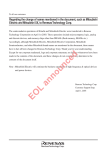
Fehlersuche/Diagnostics
Klassischer Modus
Classic Mode
1.12A
Erweiterter Display Modus
Advanced Display Mode
grün markierte Werte sind editierbar
green marked data can be edited
AS-I CIRCUIT 1
AS-I CIRCUIT 2
AS-I CIRCUIT 1
AS-I CIRCUIT 2
DIAGNOSIS
AS-I CIRCUIT 1
AS-I CIRCUIT 2
AS-I SAFETY
ADV. DIAGNOSIS
FLAGS: 0131 05
0000 0001
0011 0001
0000 0101
1 PERIPHERY_OK
0 OFFLINE_READY
0 AS-I_PWR_FAIL
1 NORMAL_OP.
1 CONFIG_ACTIVE
0 AUTO_ADDR_AVL
0 AUTO_ADDR_ASN
0 LDS.0
1 CONFIG_OK
FLAGS
ACTUAL CONFIG
LPF
AS-I MASTER
ERROR COUNTERS
LCS
FAULT DETECTOR
1 AUTO_ADDR_ENA
0 OFFLINE
1 DATA_EXCH_ACT
ACTUAL CONFIG
0A
| 1A-C
...
30A-X | 31A-D
| 1B-X
...
30A
| 31B-F
HELP:
X O.K.
D DETECTED ONLY
UNKNOWN SLAVE
P PROJ. ONLY
MISSING SLAVE
C TYPE CONFLICT
F PERIPH. FAULT
0A - .... 1A - 7A28 -C
TYPE CONFLICT
LPF LIST OF
PERIPH. FAULTS
| 1A-X
2A- | 3A4A-X | 5A-X
....
30A-X | 31A| 1B-X
2B-X | 3B-X
4B-X | 5B-X
...
30B-X | 31B-X
ERROR COUNTERS
RESET
1A 0
...
31A - 65535
1B 34
...
30B 0
LCS LIST OF
CORRUPTED SLAVES
RESET
| 1A-X
2A- | 3A4A-X | 5A-X
....
30A-X | 31A| 1B-X
2B-X | 3B-X
4B-X | 5B-X
...
30B-X | 31B-X
SAFETY SLAVES
SAFETY MONITOR
SAFETY ORIENTED
SLAVES
| 12-X | 3-R
....
30- | 31HELP:
X O.K.
R RELEASED
SAFETY MONITOR
1
...
31
SAFETY MONITOR
DIAGNOSIS
ADDR:
31
STATIC:
O.K.
CH1:
READY
CH2:
OFF
1-32:
GREEN
1-33: F YELLOW
...
FAULT DETECTOR
RESET
HISTORIC:
EFLT OVRV NOIS
ACTUAL:
ELFT OVRV NOIS
DUP ASI ADR:
0
|31B
HELP:
ELFT EARTH FAULT
OVRV OVERVOLTAGE
NOIS NOISE
DUP ASI ADR
DUPLICATE ASI
SLAVE ADDRESS
VERSION
20000919
FEATURE STRING
ZEFOD1.AS.ER
Profibus
po
we
r
P ro
fib
co us
nfi
g
e rr
U
or
AS
-i
AS
-i
a
prg c ti v
en e
ab
prj
le
m
od
e
RS 232
Mode
ESC
OK
Set
+ASI1- +ASI2-
ASI
+ PWR-
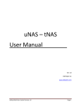
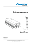
Basic Operation
The device starts in the traditional mode. You can switch between the two modes with ESC or OK.
In the advanced mode the cursor is moved by both arrow buttons. Pushing OK puts you to the superior menue (in the
drawing one step to the right side). ESC puts you back to the previous menue.
To edit data you first mark them with the cursor and then select them with OK, change them with the arrow buttons and
finally apply them with OK. Pushing ESC cancels the editing.
issue date 17.5.2005
+ASI1-
Grundsätzliche Bedienung
Das Gerät startet im traditionellen Modus. Mit ESC oder OK kann zwischen beiden Modi gewechselt werden.
Im Erweiterten Modus wird ein Cursor mit den beiden Pfeil-Tasten bewegt. OK bringt ins nächsthöhere Menü (in der
Zeichnung weiter nach rechts). ESC bringt zurück ins vorherige Menü.
Wenn Werte editiert werden, werden sie zunächst mit dem Cursor markiert, dann mit OK ausgewählt, mit den
Pfeiltasten verändert und schließlich mit OK übernommen. ESC bricht das Editieren ab.
Subject to reasonable modifications due to technical advances.
26
Copyright Murrelektronik, Printed in Germany
Murrelektronik GmbH · Falkenstr. 3 · D-71570 Oppenweiler · Phone +49 71 91-47-0 · Fax +49 71 91-47-130 · Internet http://www.murrelekronik.com
AS-i/PROFIBUS Gateway
Operating by Fullgraphic Display
In the classical mode, it is possible to change settings while the
device is in operation. This can lead to failure of the plant (e. g.
changing the address of an AS-i slave).
In the fullgraphic mode, however, the settings are protected, as long as the superior fieldbus (PROFIBUS) is running.
The device starts in the classical mode, like the former AS-i Masters with two-digit
display. Press the buttons ESC or OK to switch to the fullgraphic mode. To return
to the classical mode, simply press the ESC-button several times.
In fullgraphic mode, the selection can be moved up and down with the arrow buttons.
Pressing OK will switch to the selected function or menu (one step to the right on
the drawing, page 25). Pressing ESC will switch back to the previous menu.
To edit data values highlight them with the selection bar, press OK, then change
them with the arrow-buttons and confirm with OK. The ESC-button cancels the
editing process.
issue date 17.5.2005
All possible addresses are displayed one after the other from 1A to 31A and from
1B to 31B. Data for single slaves are displayed at the addresses 1A - 31A.
6.1
PROFIBUS (Fieldbus Interface)
6.1.1
PROFIBUS Address (PROFIBUS Station Address)
This function is for setting and changing the PROFIBUS station address.
Subject to reasonable modifications due to technical advances.
Copyright Murrelektronik, Printed in Germany
Murrelektronik GmbH · Falkenstr. 3 · D-71570 Oppenweiler · Phone +49 71 91-47-0 · Fax +49 71 91-47-130 · Internet http://www.murrelekronik.com
27
AS-i/PROFIBUS Gateway
Operating by Fullgraphic Display
The number behind "Old Address" shows the actual station address. By selecting
"New Address", this address can be changed.
6.1.2
PROFIBUS Status
The function PROFIBUS status indicates if and how many connections are active
on each PROFIBUS channel.
DPV0 = cyclic channel:
0: not active
1: active
DPV1 = acyclic channel:
0: not active
≠0: number of connections
6.2
Quick Setup
With this function you switch into configuration mode and store the actual configuration. Then the master is started in the protected mode.
To carry out the quick setup choose the menu "Store+Run". Now the actual configuration of the AS-i circuit and the connected slaves will be read.
To store the actual read configuration choose the menu "Store+Run" and confirm
the selection with the OK button.
Then in the display the submenu "Store AS-Interface Configuration" will appear.
By pressing "OK" the take over and the storing of the configuration is confirmed.
By pressing the ESC button twice you will leave the configuration mode and the
master switches to the protected mode.
If an error occurs while storing the configuration, the following error message is
displayed:
issue date 17.5.2005
PROFIBUS Errors
No Connection
Subject to reasonable modifications due to technical advances.
28
Copyright Murrelektronik, Printed in Germany
Murrelektronik GmbH · Falkenstr. 3 · D-71570 Oppenweiler · Phone +49 71 91-47-0 · Fax +49 71 91-47-130 · Internet http://www.murrelekronik.com
AS-i/PROFIBUS Gateway
Operating by Fullgraphic Display
By pressing the ESC button you leave this menu and change back to the main
menu. By selecting "Store + Prj Mode" you set the master in the protected mode.
Now you can solve errors with the help of the diagnosis and configuration.
6.3
Slave Adr Tool (Slave Addressing Tool)
This function sets and changes the addresses of both new and configured AS-i
slaves. This function replaces the handheld AS-i address programming device.
Please note that you must have selected the desired AS-i circuit usingf the arrow
and the OK button when you operate a device with two AS-i circuits (see chapter
6.5.1).
Now the new slave can be connected to the AS-i circuit. After connecting the actual address of the slave is displayed by "OLD ADDRESS".and the notice "CONNECT NEW SLV" disappears.
issue date 17.5.2005
To give the slave a new address choose the menu entry "NEW ADDRESS". Afterwards the address can be selected with the help of the arrow buttons.The (re-)
addressing is carried out by selecting the menu entry "PRG" and pressing the OK
button.
If an error occurs while addressing a slave, one of the following error messages is
displayed for about 2 seconds:
Failed: SND: slave with old address has not been detected.
Failed: SD0: slave with address zero has been detected.
Failed: SD2: slave with new address has been detected.
Failed: DE: could not delete old address.
Failed: SE: error setting new address.
Subject to reasonable modifications due to technical advances.
Copyright Murrelektronik, Printed in Germany
Murrelektronik GmbH · Falkenstr. 3 · D-71570 Oppenweiler · Phone +49 71 91-47-0 · Fax +49 71 91-47-130 · Internet http://www.murrelekronik.com
29
AS-i/PROFIBUS Gateway
Failed: AT:
Failed: RE:
6.4
Operating by Fullgraphic Display
new address could be stored temporarily only.
error reading the extended ID-code 1.
Slave Test Tool
With this function a single AS-i slave can be tested.
Please note that you must have selected the desired AS-i circuit using the arrow
and the OK button when you operate a device with two AS-i circuits (see chapter
6.5.1)
Now a warning message is displayed, that possibly by this test outputs are set and
the host may loose control of the circuit.
To start the test press the OK button, to cancel press the button ESC.
In the following menu the slave to be tested has to to be chosen by selecting the
slave address.
Afterwards the test is started by confirming the menu entry "Test".
After finishing the test all relevant informations is displayed for the tested slave.
A successful test is displayed with "OK" below the address of the tested slave.
The following information are displayed:
• Address of the tested slave
• Test is successful/not successful
• Binary inputs (digital inputs), see also “Binary Input“, chapter 6.6.3
• Binary outputs (digital outputs), see also “Binary Outputs“, chapter 6.6.4
• Analog inputs, see also “Analog Inputs“, chapter 6.6.5
• Analog outputs, see also “Analog Outputs“, chapter 6.6.6
• Perm Param (projected parameters), see also “Permanent Param (Projected
Parameter)“, chapter 6.5.7
Subject to reasonable modifications due to technical advances.
30
Copyright Murrelektronik, Printed in Germany
Murrelektronik GmbH · Falkenstr. 3 · D-71570 Oppenweiler · Phone +49 71 91-47-0 · Fax +49 71 91-47-130 · Internet http://www.murrelekronik.com
issue date 17.5.2005
• Param (actual parameters), see also “Parameter“, chapter 6.6.7
AS-i/PROFIBUS Gateway
Operating by Fullgraphic Display
• Config (actual configuration), see also “Actual Config (Actual Configuration)“,
chapter 6.7.4
• Perm Conf (projected configuration), see also “Permanent Config (Projected
Configuration Data)“, chapter 6.5.8
6.5
Setup (Configuration of the AS-i Circuit)
6.5.1
AS-i Circuit
To reach this setup menu you have to change the desired AS-i circuit by using the
arrow and the OK buttons.
The function is only implemented in the double master.
It makes possible to change the AS-i circuit that is currently active for being operated.
issue date 17.5.2005
The active circuit is marked by the cursor.
Subject to reasonable modifications due to technical advances.
Copyright Murrelektronik, Printed in Germany
Murrelektronik GmbH · Falkenstr. 3 · D-71570 Oppenweiler · Phone +49 71 91-47-0 · Fax +49 71 91-47-130 · Internet http://www.murrelekronik.com
31
AS-i/PROFIBUS Gateway
6.5.2
Operating by Fullgraphic Display
Setup (Configuration of the AS-i Circuit)
Within the menu "Setup", one of the following submenues can be chosen:
• AS-i Slave Addr (AS-i Slave Address)
• Force Offline (switch AS-i Master offline)
• Operation Mode
• Store Act Cfg (store actual detected configuration)
• Permanent Param (projected parameter)
• Permanent Cfg (projected configuration data)
• Addr. Assistant (address assistent)
• LOS (list of offline-slaves)
• Factory Reset
6.5.3
AS-i Slave Adr (Set/Change Slave Address)
With this function the address of a slave can be changed.
To change the address select the menu entry "OLD ADDRESS" and afterwards
select the address of the slave which address schould be changed. The new
address of the slave has to be set in the menu entry "NEW ADDRESS". The
addressing is carried out by pressing the OK button.
6.5.4
Force Offline
issue date 17.5.2005
This function shows the current state of the AS-i Master:
Yes: AS-i Master is offline.
No: AS-i Master is online.
With "Change", this state can be modified.
Subject to reasonable modifications due to technical advances.
32
Copyright Murrelektronik, Printed in Germany
Murrelektronik GmbH · Falkenstr. 3 · D-71570 Oppenweiler · Phone +49 71 91-47-0 · Fax +49 71 91-47-130 · Internet http://www.murrelekronik.com
AS-i/PROFIBUS Gateway
Operating by Fullgraphic Display
Switching the AS-i master offline puts the AS-i circuit into the safe state. The AS-i
master has to be offline if an AS-i slave should be addressed via the IR-interface.
6.5.5
Operation Mode
This function shows the current operation mode of the AS-i master:
Protected Mode: Protected mode
Config Mode:
Configuration mode
With "Change" you can switch to the other operation mode.
Only in configuration mode parameters and configuration data can be stored.
6.5.6
Store Act Cfg (Store Actual Detected Configuration)
This function can only be executed in configuration mode.
This function enables you to store the configuration of all slaves which are connected and detected on the selected AS-i circuit.
If "Store" was successful, the LED "Config error" is off. The configuration is stored,
the configuration error has been eliminated.
If one of the connected slaves has a peripheral fault, the LED "Config error" will
flash.
If the AS-i master is in protected mode, the following error message will appear:
"Failed No Config Mode"
If an AS-i slave with address zero exists, storing the configuration will be confirmed
with "OK". However, the configuration error remains because address zero is not
a valid operating address for storing a slave.
issue date 17.5.2005
6.5.7
Permanent Param (Projected Parameter)
This function allows you to set the permanent parameters. A list of all slaves is displayed from 1A - 31A and from 1B - 31B. The permanent parameters for single
slaves are set from address 1A - 31A. The parameter is shown as a hexadecimal
value behind the slave address.
Subject to reasonable modifications due to technical advances.
Copyright Murrelektronik, Printed in Germany
Murrelektronik GmbH · Falkenstr. 3 · D-71570 Oppenweiler · Phone +49 71 91-47-0 · Fax +49 71 91-47-130 · Internet http://www.murrelekronik.com
33
AS-i/PROFIBUS Gateway
6.5.8
Operating by Fullgraphic Display
Permanent Config (Projected Configuration Data)
With this function the projected configuration data can be projected. The values for
the configuration data are displayed behind the slave address in the following order:
IO (I/O-configuration) ID (ID-configuration) xID1 (extended ID1)
xID2 (extended ID2).
6.5.9
AS-i Address Assistant
The AS-i address assistant helps you to set up the AS-i circuit quickly. Once you
have stored the AS-i configuration, the AS-i address assistant addresses a new
AS-i slave with address zero to the desired address.
Selecting "Assistant on" or "Assistant off" switches the AS-i address assistant on
or off. The current state of the AS-i address assistant is displayed:
Assistant on: AS-i address assistant is switched on.
Assistant off: AS-i address assistant is switched off.
Procedure:
1. Store AS-i Configuration to the master. This can be done very comfortably with
the Windows software AS-i Control Tools (Master | Write configuration to the
AS-i Master ...), or directly with the fullgraphic display (see chapter 6.5.8).
2. All AS-i slaves have to be addressed to 0 or to the desired address. The slaves
must be disconnected from the AS-i circuit.
3. Start the AS-i address assistant.
4. Now connect the AS-i slaves one after the other. The last line of the display of
the AS-i address assistant shows which AS-i slave has to be connected next.
LOS (List of Offline Slaves)
See also "Advanced Diagnostics for AS-i Masters", chapter 7.
Subject to reasonable modifications due to technical advances.
34
Copyright Murrelektronik, Printed in Germany
Murrelektronik GmbH · Falkenstr. 3 · D-71570 Oppenweiler · Phone +49 71 91-47-0 · Fax +49 71 91-47-130 · Internet http://www.murrelekronik.com
issue date 17.5.2005
6.5.10
AS-i/PROFIBUS Gateway
Operating by Fullgraphic Display
With "Clear all" and "Set all" you can delete or set a single bit for each AS-i slave
address. Underneath there is a list of all slaves, by which the LOS bit can be set
or deleted by individualy selecting of the LOS bit.
Empty field: LOS bit deleted
X:
LOS bit set
6.5.11
Auto Adr Enable (Enable Automatic Address Programming)
With this function the automatic address programming can be released or locked.
Meaning of the displayed mode:
Enable: Automatic address programming is released.
Disable: Automatic address programming is locked.
With "CHANGE" you can switch to the other mode.
6.5.12
Factory Reset
With this function the master can be reseted to the factory setting. The reset can
be chosen by selecting the menu entry "DO RESET".
issue date 17.5.2005
This function schould be chosen only in case of emergency,
because all stored settings are reset to factory setting and therfore a
perfect communication and working of the master is not guarnateed
any more.
The master and the AS-i circuit have to be recommissioned and
reprojected again after a successful "Reset".
By double masters the reset have an effect on both AS-i masters!
Subject to reasonable modifications due to technical advances.
Copyright Murrelektronik, Printed in Germany
Murrelektronik GmbH · Falkenstr. 3 · D-71570 Oppenweiler · Phone +49 71 91-47-0 · Fax +49 71 91-47-130 · Internet http://www.murrelekronik.com
35
AS-i/PROFIBUS Gateway
Operating by Fullgraphic Display
6.6
IO + Param. Test (Testing AS-i In- and Outputs as well as reading and
writing AS-i Parameters)
6.6.1
AS-i Circuit
To reach this setup menu you have to change the desired AS-i circuit by using the
arrow and the OK buttons.
The function is only implemented in the double master.
It makes possible to change the AS-i circuit that is currently active for being operated.
The active circuit is marked by the cursor.
6.6.2
IO + Param. Test (Testing AS-i In- and Outputs as well as reading and
writing AS-i Parameters)
Before changing to the menu the following warning message will displayed:
"Warning: Outputs may be set and Host may lose control."
The menu "IO + Param.Test" enables you to choose one of the following submenues:
• Binary Inputs
• Binary Outputs
• Analog Inputs
• Analog Outputs
issue date 17.5.2005
• Parameter
Subject to reasonable modifications due to technical advances.
36
Copyright Murrelektronik, Printed in Germany
Murrelektronik GmbH · Falkenstr. 3 · D-71570 Oppenweiler · Phone +49 71 91-47-0 · Fax +49 71 91-47-130 · Internet http://www.murrelekronik.com
AS-i/PROFIBUS Gateway
6.6.3
Operating by Fullgraphic Display
Binary Input
This list shows the state of the binary inputs for all AS-i slaves.
0: Input deleted
1: Input set
6.6.4
Binary Outputs
This function shows the state of the binary outputs for all AS-i slaves.
0: Output deleted
1: Output set
The binary outputs can be changed after selecting the desired AS-i slave.
6.6.5
Analog Inputs
This function shows the state of the analog inputs for all AS-i slaves.
The display is as follows:
AS-i slave address, hexadecimal 16 bit value, bar display indicating the input
or output value
issue date 17.5.2005
An eventual value overflow is displayed by "Overfl" additionally.
Subject to reasonable modifications due to technical advances.
Copyright Murrelektronik, Printed in Germany
Murrelektronik GmbH · Falkenstr. 3 · D-71570 Oppenweiler · Phone +49 71 91-47-0 · Fax +49 71 91-47-130 · Internet http://www.murrelekronik.com
37
AS-i/PROFIBUS Gateway
6.6.6
Operating by Fullgraphic Display
Analog Outputs
This function shows the state of the analog outputs for all AS-i slaves.
The display is as follows:
AS-i slave address, hexadecimal 16 bit value, bar display
An possible value overflow is displayed by "Overfl" additionally.
The analog outputs can be changed after selecting the desired AS-i slave.
6.6.7
Parameter
This function shows the hexadecimal value of the current AS-i parameters for all
AS-i slaves.
issue date 17.5.2005
The actual AS-i parameters can be changed after selecting the desired slave
address.
Subject to reasonable modifications due to technical advances.
38
Copyright Murrelektronik, Printed in Germany
Murrelektronik GmbH · Falkenstr. 3 · D-71570 Oppenweiler · Phone +49 71 91-47-0 · Fax +49 71 91-47-130 · Internet http://www.murrelekronik.com
AS-i/PROFIBUS Gateway
Operating by Fullgraphic Display
6.7
Diagnosis (Normal AS-i Diagnosis)
6.7.1
AS-i Circuit
To reach this setup menu you have to change the desired AS-i circuit by using the
arrow and the OK buttons.
The function is only implemented in the double master.
It makes possible to change the AS-i circuit that is currently active for being operated.
The active circuit is marked by the cursor.
6.7.2
Diagnosis (Normal AS-i Diagnosis)
The menu "Diagnosis" enables you to choose one of the following submenues:
• Flags (EC-Flags: Execution control flags)
• Actual Config (actual configuration)
• LPF (list of periphery faults)
issue date 17.5.2005
• AS-i Master (Info)
Subject to reasonable modifications due to technical advances.
Copyright Murrelektronik, Printed in Germany
Murrelektronik GmbH · Falkenstr. 3 · D-71570 Oppenweiler · Phone +49 71 91-47-0 · Fax +49 71 91-47-130 · Internet http://www.murrelekronik.com
39
AS-i/PROFIBUS Gateway
6.7.3
Operating by Fullgraphic Display
Flags
This function shows the EC-flags hexadecimaly, binary and as single bits beginning with the lowest-order bit.
Arrangement of the bits within the byte:
Byte
Bit value: 27 26 25 24 23 22 21 20
Bit.
7
6
5
4
3
2
1
0
Byte 1:
Bit 0: Periphery_OK
This flag is set, if no AS-i slave signs a periphery fault.
Byte 2:
Bit 0: Config_OK
The flag is set, if the projected configuration corresponds with the actual configuration.
Bit 1: LDS.0
The flag is set, if an AS-i slave with address 0 has been detected.
Bit 2: Auto_Addr_Asn
The flag is set, if the automatic addressing is possible
(AUTO_ADDR_ENABLE = 1; no "incorrect" AS-i slave is conntected to
AS-i).
Bit 4: Config_Active
The flag is set in the configuration mode and is reset in the protected
mode.
Subject to reasonable modifications due to technical advances.
40
Copyright Murrelektronik, Printed in Germany
Murrelektronik GmbH · Falkenstr. 3 · D-71570 Oppenweiler · Phone +49 71 91-47-0 · Fax +49 71 91-47-130 · Internet http://www.murrelekronik.com
issue date 17.5.2005
Bit 3: Auto_Addr_Avl
The flag is set, if the automatic addressing is possible. This means that
exactly one slave is failed.
AS-i/PROFIBUS Gateway
Operating by Fullgraphic Display
Bit 5: Normal_Op.
The flag is set, if the AS-i master is in normal operation.
Bit 6: AS-i Pwr Fail
The flag is set, if the AS-i circuit is not sufficiently powered.
Bit 7: Offline_Ready
The flag is set, if the AS-i master is in the offline phase.
Byte 3:
Bit 0: Data_Exch_Act
If the flag "Data Exchange Active" is set, the data exchange is released
with the AS-i slaves in the data exchange phase. If the bit is not set, the
data exchange with AS-i slaves will be locked. Instead of data telegramms READ_ID telegramms will be sent.
The bit is set by the AS-i master by change over in the offline phase.
Bit 1: Offline
This bit is set if the operating mode offline is to be or already taken.
Bit 2: Auto_Addr_Ena
This flag indicates if the automatic addressing is locked (bit = 0) or released (bit = 1) by the user.
(See also „Get Flags (GET_FLAGS)“, page 71)
6.7.4
Actual Config (Actual Configuration)
This function shows the state of the actual configuration of the individual AS-i slaves.
At the end of the list there is a help text describing the abbreviations:
X (O.K.):
The configuration data of the detected AS-i slave matches the
projected configuration data.
D (Detected Only): An AS-i slave is detected at this address, but not projected.
issue date 17.5.2005
P (Projected Only): An AS-i slave is projected at this address, but not detected.
C (Type Conflict):
The configuration data of the detected AS-i slave does not
match the projected configuration data. The actual detected
configuration of the connected AS-i slave is displayed.
F (Periph. Fault):
The AS-i slave has a peripheral fault.
After selecting the desired AS-i slave address the values for the actual configuration data are displayed behind the respective address in the following order:
Subject to reasonable modifications due to technical advances.
Copyright Murrelektronik, Printed in Germany
Murrelektronik GmbH · Falkenstr. 3 · D-71570 Oppenweiler · Phone +49 71 91-47-0 · Fax +49 71 91-47-130 · Internet http://www.murrelekronik.com
41
AS-i/PROFIBUS Gateway
Operating by Fullgraphic Display
IO (I/O-configuration) ID (ID-configuration) xID1 (extended ID1)
xID2 (extended ID2)
Furthermore the state of the configuration is displayed in plain text.
If no AS-i slave is detected and no AS-i slave is projected at a certain address, four
dots instead of the configuration data are displayed.
6.7.5
LPF (List of Periphery Faults)
The list shows AS-i slaves, which have released a peripheral fault.
Empty field: Periphery O.K.
X:
Peripheral fault
6.7.6
AS-i Master (Info)
This function shows information about the version and the features of the AS-i master.
Version xxxxxxxx (date of the firmware)
Feature String xxxxxxxxxxxxxxxx
6.8
Adv. Diagnosis (Advanced AS-i Diagnosis)
See also "Advanced Diagnostics for AS-i Masters", chapter 7.
In the menu "Adv. Diagnosis", the following submenues can be found:
issue date 17.5.2005
• Error Counters
• LCS (list of slaves, that produced a configuration error)
• Fault Detector
Subject to reasonable modifications due to technical advances.
42
Copyright Murrelektronik, Printed in Germany
Murrelektronik GmbH · Falkenstr. 3 · D-71570 Oppenweiler · Phone +49 71 91-47-0 · Fax +49 71 91-47-130 · Internet http://www.murrelekronik.com
AS-i/PROFIBUS Gateway
6.8.1
Operating by Fullgraphic Display
Error Counters
This list shows the error counter for each single AS-i slave.
Furthermore the number of power failures on AS-i (APF) is displayed.
By selecting "Reset", the error counters are reset to 0.
6.8.2
LCS (List of Slaves having caused a Configuration Error)
This list shows for each single AS-i slave whether at least one configuration error
was caused by an enormous telegram transmission. This function is especially important if the configuration error only occurs short-time.
Empty field: No error
X:
AS-i slave caused a configuration error.
6.8.3
Fault Detector
The menu "Fault Detector" shows information about the AS-i detector and allows
deleting of the AS-i detector´s history. Furthermore a list of abbreviations in plain
language can be found is in the section "Help".
issue date 17.5.2005
By selecting "Reset" the history of the AS-i detector can be deleted.
Subject to reasonable modifications due to technical advances.
Copyright Murrelektronik, Printed in Germany
Murrelektronik GmbH · Falkenstr. 3 · D-71570 Oppenweiler · Phone +49 71 91-47-0 · Fax +49 71 91-47-130 · Internet http://www.murrelekronik.com
43
AS-i/PROFIBUS Gateway
Operating by Fullgraphic Display
In the section "Historic" the appeared error messages of the AS-i detector are listed since the last "Reset".
In the section "Actual." the actual appeared error messages of the AS-i detector
are listed.
Following error messages are possible:
• Duplicate address (the 2 lowest slave addresses are displayed, at which a duplicate address exist).
• Earth faults
• Noise
• Overvoltage
6.9
AS-i Safety
This function shows information about the safety slaves and the safety monitor:
• Safety Slaves
• Safety Monitor
6.9.1
Safety Slaves
This list shows the "safety-directed input slaves" ("AS-i Safety at Work"), by which
the safety function is released.
Empty field
X:
o.k.
R:
released
The slaves according to profile S-7.B or S-0.B are listed here, by which all 4 bits
in the IDI are deleted. Therefore slaves with 2 contacts are entered only if both
contacts are released.
Only CDI and IDI are used for creating this list. Safety slaves which are projected
but not existing, and existing slaves sending a wrong code are not listed here.
This list is not constantly updated; it is created from the image of the digital inputs
IDI, if required.
Subject to reasonable modifications due to technical advances.
44
Copyright Murrelektronik, Printed in Germany
Murrelektronik GmbH · Falkenstr. 3 · D-71570 Oppenweiler · Phone +49 71 91-47-0 · Fax +49 71 91-47-130 · Internet http://www.murrelekronik.com
issue date 17.5.2005
Since the safety function of a safety-directed input slave can be released even if
the slave does not exchange data with the AS-i master, the list may be used only
in combination with the ec-flags.
AS-i/PROFIBUS Gateway
6.9.2
Operating by Fullgraphic Display
Safety Monitor
The AS-i safety monitor reads the diagnosis data out of the AS-i safety monitor and
shows this data in the display. The meaning of the shown diagnosis can be seen
in the description of the safety monitor.
6.10
Language
With this function the language of the user interface can be changed by using the
arrow and OK buttons.
Following languages are available:
• German
• Englisch
• French
issue date 17.5.2005
• Italian
Subject to reasonable modifications due to technical advances.
Copyright Murrelektronik, Printed in Germany
Murrelektronik GmbH · Falkenstr. 3 · D-71570 Oppenweiler · Phone +49 71 91-47-0 · Fax +49 71 91-47-130 · Internet http://www.murrelekronik.com
45
AS-i/PROFIBUS Gateway
7
Advanced Diagnostics for AS-i Masters
Advanced Diagnostics for AS-i Masters
The advanced AS-i diagnostics serve to locate occasionally occurring errors and
to judge the quality of data transmission on AS-i without additional diagnostics
tools.
"AS-i Control Tools" (software for comfortable commissioning of AS-Interface and
programming of AS-i Control) supports the operation of the advanced diagnostics
(LCS, error counters and LOS).
7.1
List of Corrupted AS-i Slaves (LCS)
The LCS contains the history of the delta list. Besides the list of projected slaves
(LPS), the list of detected slaves (LDS) and the list of activated slaves (LAS), a
fourth list, the list of corrupted slaves (LCS), is created by AS-i masters with advanced diagnostics in order to locate occasionally occurring short-time configuration errors. This list contains entries of all AS-i slaves which were responsible for
at least one configuration error since powering up the AS-i master or reading the
list. Short-time AS-i power failures are listed in the LCS at the position of AS-i slave
with address 0.
With every read access the LCS will be deleted.
The last short-time configuration error can also be displayed on the
AS-i master:
Pressing the "Set" button of the AS-i master shows the AS-i slave
which was responsible for the last short-time configuration error. If
there was a short-time AS-i power failure the display shows "39"
after pressing the "Set" button.
This function is only available if the device is in the normal operation
mode of the protected mode (display empty) or in the off-line-phase.
7.2
Protocol Analysis: Counters of Corrupted Data Telegrams
The AS-i master with advanced diagnostics has a counter of telegram repetitions
for each AS-i slave, which count up every time a currupted data telegram has been
found. This makes possible to judge the quality of the AS-i network, even if only a
few corrupted telegrams occured and the AS-i slave did not cause any configuration errors.
The protocol analysis is included in the sofware "AS-i Control Tools" by using the
command master | AS-i Diagnostics.
Subject to reasonable modifications due to technical advances.
46
Copyright Murrelektronik, Printed in Germany
Murrelektronik GmbH · Falkenstr. 3 · D-71570 Oppenweiler · Phone +49 71 91-47-0 · Fax +49 71 91-47-130 · Internet http://www.murrelekronik.com
issue date 17.5.2005
The counter values can be read via the host interface and will be
deleted with every read access. The counter value is limited to 254.
255 will cause a counter overflow.
AS-i/PROFIBUS Gateway
7.3
Advanced Diagnostics for AS-i Masters
Offline Phase on Configuration Errors (LOS)
The AS-i masters with advanced diagnostics offer the possibility to put themselves
into the offline phase when a configuration error on the AS-Interface occurs. This
way the security of the application can be ensured. The reaction to a configuration
error is very fast and the host can be relieved from this task. If there are any problems on the AS-i network, the AS-interface can be switched to a secure state.
There are two different ways to parameterize the AS-i master for this feature:
• Every configuration error during normal operation in protected mode releases
the off-line phase.
• For each slave address, it can be chosen whether a configuration error on this
address will cause the offline phase or not. This information is stored in the list
of offline slaves (LOS).
The user himself can decide how the system reacts to a configuration error on
the AS-Interface. The AS-i master can release the off-line phase in critical situations, i. e. only with certain slave addresses, whereas in less critical situations
(if one of the other AS-i slaves has a configuration error) only the error message
is sent to the host, but AS-i is still running.
The parameterization "off-line phase on configuration error" is also supported by
the "AS-i Control Tools" (command Master | Identity | Offline on configuration error).
Two ways to reset the error message "OFFLINE BY LOS" are possible:
1. Deleting of the complete list LOS of the affected AS-i circuit ("CLEAR ALL").
2. Voltage reset at the affected AS-i circuit.
By voltage reset at the As-i circuit 1 the complete double gateway
will be shut down.
7.4
Functions of the AS-i Fault Detector
7.4.1
Recognition of Duplicate Addresses
If two slaves have the same address in an AS-i circuit, a duplicate address exists.
Because of this error the master can not send a request to each slave seperately.
At that time both repsonses overlap themselves on the line, it is impossible for the
master to recognize the slave response safely. It exists an unstable network behaviour.
issue date 17.5.2005
The function "recognition of duplicate addresses" allows to recognize a duplicate
address and to indicate this both via PROFIBUS and in the AS-i Control Tools.
Subject to reasonable modifications due to technical advances.
Copyright Murrelektronik, Printed in Germany
Murrelektronik GmbH · Falkenstr. 3 · D-71570 Oppenweiler · Phone +49 71 91-47-0 · Fax +49 71 91-47-130 · Internet http://www.murrelekronik.com
47
AS-i/PROFIBUS Gateway
Advanced Diagnostics for AS-i Masters
A duplicate address causes a configuration error und will be shown in the diplay of
the master.
Duplicate addresses can be recognized only in the AS-i segment
directly at the master. If both slaves participate in a duplicate
address located behind a repeater, the recognition of duplicate
addresses is impossible.
7.4.2
Earth Fault Detector
If one of the both AS-i lines is connected conductivly with the plant earth, it exists
an earth fault. This error limits the fail-safe characteristic of the AS-i transmission
substantially.
Earth faults are indicated in the master´s display as well as via PROFIBUS and the
AS-i Control Tools.
For recognition of earth faults the master must be grounded with the
function earth.
7.4.3
Noise Detector
The noise detector detects alternating voltages on AS-i, which are not produced
by AS-i master or AS-i slaves. These interference voltages can cause telegram
disturbances.
A frequent cause are insufficiently shielded frequency inverters or awkwardly shifted cables.
Noises are indicated in the master´s display as well as via PROFIBUS and the AS-i
Control Tools.
7.4.4
Overvoltage Detector
Overvoltages are present, if the AS-i line, whose veins lie normally electrically
symmetrically to the plant earth, are strongly electrically raised. A cause can be
e.g. power-on procedures of large consumers. However sometimes overvoltages
don´t generally disturb AS-i communication, but can release incorrect signals of
sensors.
issue date 17.5.2005
Overvoltages are indicated in the master´s display as well as via PROFIBUS and
the AS-i Control Tools.
Subject to reasonable modifications due to technical advances.
48
Copyright Murrelektronik, Printed in Germany
Murrelektronik GmbH · Falkenstr. 3 · D-71570 Oppenweiler · Phone +49 71 91-47-0 · Fax +49 71 91-47-130 · Internet http://www.murrelekronik.com
AS-i/PROFIBUS Gateway
8
PROFIBUS DP
PROFIBUS DP
This chapter contains all necessary information to operate the AS-i/PROFIBUS
gateways in a PROFIBUS DP network.
8.1
DP Telegrams
8.1.1
Diagnosis
DP Diagnosis - Single Master
PDU byte
user byte
1
–
station_status 1
2
–
station_status 2
3
–
station_status 3
4
–
master address
5
–
ident high
6
–
ident low
7
1
header
8
2
type
9
3
slot
10
4
spec
11
5
ec-flags (high)
12
6
ec-flags (low)
13
7
delta (0…7)
14
8
delta (8…15)
…
…
…
…
DP V1
user
20
14
delta (56…63)
21
15
LPF (0…7)
…
…
…
…
28
22
LPF (56 … 63)
ec-flags (high):
Bit 0:
Bit 1 … Bit 3
Bit 4:
Bit 5:
Bit 6:
Bit 7:
issue date 17.5.2005
DP
periphery fault
reserved
earth fault
over voltage
noise
duplicate address
ec-flags (low):
Bit 0:
configuration error
Bit 1:
slave with address0 detected
Bit 2:
Auto_address_assignment not possible
Bit 3:
Auto_address_assingment available
Bit 4:
configuration mode actice
Bit 5:
not in normal operation
Subject to reasonable modifications due to technical advances.
Copyright Murrelektronik, Printed in Germany
Murrelektronik GmbH · Falkenstr. 3 · D-71570 Oppenweiler · Phone +49 71 91-47-0 · Fax +49 71 91-47-130 · Internet http://www.murrelekronik.com
49
AS-i/PROFIBUS Gateway
Bit 6:
Bit 7:
PROFIBUS DP
AS-i power fail
AS-i master is offline
Delta List: List of AS-i slaves with configuration error.
1: ConfigError
0: no ConfigError
LPF: List of AS-i slaves with periphery fault.
1: periphery fault
0: no periphery fault
Each element of the user diagnosis (ec-flags and slave lists) can be switched off
by setting the appropriate bit in the parameter telegram.
Each element which is not used will be filled up with zeroes. This way the data elements in the diagnosis telegram will keep its designated position (and clear text
diagnosis still fits to the data).
Only if an element at the end of the user diagnosis is not used, the length of the
diagnosis will be shortened.
ExtDiag will be set if at least one of the following conditions is fulfilled:
• ConfigError ≡ 1
• APF ≡ 1
• PeripheryFault ≡ 1
The conditions when to set the ExtDiag bit can be chosen using the user parameters or the commands of the command interface.
The GSD file includes the following presettings:
• The diagnosis transmitts ec-flags, delta list and LPF.
issue date 17.5.2005
• ExtDiag will be set if ConfigError = 1 and APF = 1. ExtDiag will not be set if there
is a periphery fault.
Subject to reasonable modifications due to technical advances.
50
Copyright Murrelektronik, Printed in Germany
Murrelektronik GmbH · Falkenstr. 3 · D-71570 Oppenweiler · Phone +49 71 91-47-0 · Fax +49 71 91-47-130 · Internet http://www.murrelekronik.com
AS-i/PROFIBUS Gateway
PROFIBUS DP
If a double master is being used, the User-Diagnosis-Bytes 5 to 30 represent ASi network 1 and the User-diagnosis bytes 31 to 56 represent AS-i network 2.
DP Diagnosis - Double Master
PDU byte
user byte
1
–
station_status 1
2
–
station_status 2
3
–
station_status 3
4
–
master address
5
–
ident high
6
–
ident low
7
1
header
8
2
type
9
3
slot
10
4
spec
11
5
ec-flags (high), circuit 1
12
6
ec-flags (low), circuit 1
13
7
delta (0…7), circuit 1
14
8
delta (8…15), circuit 1
…
…
…
…
20
14
delta (56…63), circuit 1
21
15
LPF (0…7), circuit 1
…
…
…
…
28
22
LPF (56 … 63), circuit 1
29
23
reserved
…
…
…
…
36
30
reserved
37
31
ec-flags (high), circuit 2
38
32
ec-flags (low), circuit 2
39
33
delta (0…7), circuit 2
40
34
delta (8…15), circuit 2
…
…
…
…
46
40
delta (56…63), circuit 2
47
41
LPF (0…7), circuit 2
…
…
…
48
LPF (56 … 63), circuit 2
DP V1
user
issue date 17.5.2005
54
DP
Subject to reasonable modifications due to technical advances.
Copyright Murrelektronik, Printed in Germany
Murrelektronik GmbH · Falkenstr. 3 · D-71570 Oppenweiler · Phone +49 71 91-47-0 · Fax +49 71 91-47-130 · Internet http://www.murrelekronik.com
51
AS-i/PROFIBUS Gateway
8.1.1.1
PROFIBUS DP
Parameters
With the user parameters you can choose if and which slave list will be displayed
in the diagnosis. Furthermore you can select which conditions have to be fulfilled
to set the ExtDiag bit within the diagnosis telegram.
DP Parameters - Single Master
PDU byte
user byte
1
–
Station_Status
DP
DP V1
user
default
2
–
WD_Fact_1
3
–
WD_Fact_2
4
–
min Tsdr
5
–
Ident High
6
–
Ident Low
7
–
Group_Ident
8
1
DPV Status 1
8016
0016
9
2
DPV Status 2
10
3
DPV Status 3
11
4
User Byte 1
0B16
12
5
User Byte 2
0616
13
6
User Byte 3
0016
0016
The bits in "User Byte 1" and "User Byte 3" have the following meanings:
User Byte 1
27
26
25
default
24
22
21
20
LPF
–
D
F
1
0
1
1
24
23
22
21
20
-
0
0
0
23
User Byte 2
27
default
26
25
FD
0
CS
PF
APF
CF
–
0
0
0
0
1
1
0
23
22
21
20
User Byte 3
2
default
7
2
6
2
5
24
–
0
0
0
D:
1: Delta list will be transmitted in the diagnosis
0: Delta list will not be transmitted
Subject to reasonable modifications due to technical advances.
52
issue date 17.5.2005
LPF: 1: LPF will be transmitted in the diagnosis
0: LPF will not be transmitted
Copyright Murrelektronik, Printed in Germany
Murrelektronik GmbH · Falkenstr. 3 · D-71570 Oppenweiler · Phone +49 71 91-47-0 · Fax +49 71 91-47-130 · Internet http://www.murrelekronik.com
AS-i/PROFIBUS Gateway
F:
PROFIBUS DP
1: EC-flags will be transmitted in the diagnosis
0: EC-flags will not be transmitted
FD: If this bit is set, the PROFIBUS diagnosis is refreshed only if the PROFIBUS
norm dictates this ("freeze diagnosis"). In doubt the data of the PROFIBUS
masters diagnosis are not up to date.
CS: 1: ExtDiag will be set if the LCS is not empty
0: ExtDiag will not be set if the LCS is not empty
PF: 1: ExtDiag will be set if there is a periphery fault at the AS-i line
0: ExtDiag will not be set.
APF: 1: ExtDiag will be set if there is an AS-i Power Fail
0: ExtDiag will not be set.
CF: 1: ExtDiag will be set if there is a configuration error
0: ExtDiag will not be set.
The GSD's default user parameter telegram is:
8016
0016
0016
0B16
0616
0016
(DPV1 enabled, diagnosis settings according to chapter 8.1.1)
If a double master is being used, the data for AS-i circuit are transmitted in the user
parameter bytes 4 to 6. For circuit 2 3 additional bytes are added.
DP Parameters - Double Master
issue date 17.5.2005
PDU byte user byte
DP
DP V1
user
default
1
–
Station_Status
2
–
WD_Fact_1
3
–
WD_Fact_2
4
–
min Tsdr
5
–
Ident High
6
–
Ident Low
7
–
Group_Ident
8
1
DPV Status 1
8016
9
2
DPV Status 2
0016
10
3
DPV Status 3
11
4
User Byte 1, circuit 1
0B16
12
5
User Byte 2, circuit 1
0616
13
6
User Byte 3, circuit 1
0016
14
7
User Byte 1, circuit 2
0B16
15
8
User Byte 2, circuit 2
0616
16
9
User Byte 3, circuit 2
0016
Subject to reasonable modifications due to technical advances.
0016
Copyright Murrelektronik, Printed in Germany
Murrelektronik GmbH · Falkenstr. 3 · D-71570 Oppenweiler · Phone +49 71 91-47-0 · Fax +49 71 91-47-130 · Internet http://www.murrelekronik.com
53
AS-i/PROFIBUS Gateway
8.1.2
PROFIBUS DP
Configuration DP V0 (cyclic data)
The configuration of the AS-i/PROFIBUS gateways is made with the GSD file.
Therefore the provided GSD file has to be imported into your PROFIBUS configuration tool.
8.1.2.1
AS-i-V2.1 Mode
In AS-i V2.1 mode the input and output data field can be used with various "special
IDs".
The advantages of special input and output IDs are, that they can include up to 64
elements (bytes or words), and that the length of input and output data can be different. Additionally, "manufacturer specific" data bytes describing the ID type are
possible. These "manuafaturer specific" data bytes describe the which type ID is.
The GSD file offers here several combinations (several lengths) for transmitting I/
O date, command interface (management) and analog data.
Therefore the analog data can be transmitted directly in the process data channel
and do not have to be requested by the slower DP V1 commands.
The detailed possibilities:
Length
Description
digital input (slaves 0 - 7)
8 bytes
digital input (slaves 0 - 15)
12 bytes
digital input (slaves 0 - 23)
16 bytes
digital input (slaves 0 - 31)
20 bytes
digital input (slaves 0 - 7B)
24 bytes
digital input (slaves 0 - 15B)
28 bytes
digital input (slaves 0 - 23B)
32 bytes
digital input (slaves 0 - 31B)
Length
4 bytes
Description
digital output (slaves 0 - 7)
8 bytes
digital output (slaves 0 - 15)
12 bytes
digital output (slaves 0 - 23)
16 bytes
digital output (slaves 0 - 31)
20 bytes
digital output (slaves 0 - 7B)
24 bytes
digital output (slaves 0 - 15B)
28 bytes
digital output (slaves 0 - 23B)
32 bytes
digital output (slaves 0 - 31B)
Length
16 bytes
Description
digital in/out (slaves 0 - 31)
16 Bytes
digital in/out (slaves 0B - 31B)
32 bytes
digital in/out (slaves 0 - 31B)
Subject to reasonable modifications due to technical advances.
54
issue date 17.5.2005
4 bytes
Copyright Murrelektronik, Printed in Germany
Murrelektronik GmbH · Falkenstr. 3 · D-71570 Oppenweiler · Phone +49 71 91-47-0 · Fax +49 71 91-47-130 · Internet http://www.murrelekronik.com
AS-i/PROFIBUS Gateway
PROFIBUS DP
Length
Description
2 bytes
management (command interface)
4 bytes
management (command interface)
8 bytes
management (command interface)
11 bytes
management (command interface)
12 bytes
management (command interface)
34 bytes
management (command interface)
36 bytes
management (command interface)
Length
Description
24 bytes
analog input (slaves 29 - 31)
56 bytes
analog input (slaves 25 - 31)
88 bytes
analog input (slaves 21 - 31)
120 bytes
analog input (slaves 17 - 31)
128 bytes
analog input (slaves 16 - 31)
16 bytes
analog input (slaves 14 - 15)
Length
Description
24 bytes
analog output (slaves 29 - 31)
56 bytes
analog output (slaves 25 - 31)
88 bytes
analog output (slaves 21 - 31)
120 bytes
analog output (slaves 17 - 31)
128 bytes
analog output (slaves 16 - 31)
16 bytes
analog output (slaves 14 - 15)
Length
Description
2 bytes … 128 bytes analog input data circuit 1, dynamic1
2 bytes … 128 bytes analog output data circuit 1, dynamich1
2 bytes … 128 bytes analog input data circuit 2, dynamic1
2 bytes … 128 bytes analog output data circuit 2, dynamic1
2 bytes
flags and AS-i detector circuit 1
2 bytes
flags and AS-i detector circuit 2
issue date 17.5.2005
1. Module parameters necessarily
Subject to reasonable modifications due to technical advances.
Copyright Murrelektronik, Printed in Germany
Murrelektronik GmbH · Falkenstr. 3 · D-71570 Oppenweiler · Phone +49 71 91-47-0 · Fax +49 71 91-47-130 · Internet http://www.murrelekronik.com
55
AS-i/PROFIBUS Gateway
PROFIBUS DP
8.1.3
I/O Data
8.1.3.1
Process data
In V2.1 mode the AS-i I/O data are mapped in the process data as known from the
Siemens and AS-i/InterBus masters. This means that the lower nibble describes
the data of the AS-i slave with the higher slave address. The ec-flags or hi-flags
are additionaly mapped at the nibble of AS-i slave 0.
27
26
F3
F2
0
24
23
22
F1
F0
D3
D2
flags
21
20
slave 1/1A
D1
1
slave 2/2A
slave 3/3A
2
slave 4/4A
slave 5/5A
3
slave 6/6A
slave 7/7A
4
slave 8/8A
slave 9/9A
5
slave 10/10A
slave 11/11A
6
slave 12/12A
slave 13/13A
7
slave 14/14A
slave 15/15A
8
slave 16/16A
slave 17/17A
9
slave 18/18A
slave 19/19A
10
slave 20/20A
slave 21/21A
11
slave 22/22A
slave 23/23A
12
slave 24/24A
slave 25/25A
13
slave 26/26A
slave 27/27A
14
slave 28/28A
slave 29/29A
15
slave 30/30A
slave 31/31A
16
reserved
slave 1B
17
slave 2B
slave 3B
18
slave 4B
slave 5B
19
slave 6B
slave 7B
20
slave 8B
slave 9B
21
slave 10B
slave 11B
22
slave 12B
slave 13B
23
slave 14B
slave 15B
24
slave 16B
slave 17B
25
slave 18B
slave 19B
26
slave 20B
slave 21B
27
slave 22B
slave 23B
28
slave 24B
slave 25B
29
slave 26B
slave 27B
30
slave 28B
slave 29B
31
slave 30B
slave 31B
Subject to reasonable modifications due to technical advances.
56
25
D0
Copyright Murrelektronik, Printed in Germany
Murrelektronik GmbH · Falkenstr. 3 · D-71570 Oppenweiler · Phone +49 71 91-47-0 · Fax +49 71 91-47-130 · Internet http://www.murrelekronik.com
issue date 17.5.2005
byte
AS-i/PROFIBUS Gateway
PROFIBUS DP
Flags
input data
output data
F0 ConfigError
Offline
F1 APF
LOS master bit
F2 PeripheryFault
→ ConfigurationMode
F3 ConfigurationActive
→ ProtectedMode
ConfigError:
0 = ConfigOK, 1 = ConfigError
APF:
0 = AS-i Power OK, 1 = AS-i Power Fail
PeripheryFault:
0 = PeripheryOK, 1 = PeripheryFault
ConfigurationActive: 0 = ConfigurationActive, 1 = ConfigurationInactive
Offline:
0 = Online, 1 = Offline
LOS-Master-Bit
0 = Offline by ConfigError deactivated
1 = Offline by ConfigError activated
A rising edge of F2 and F3 switch the master to the desired mode.
A rising edge of the "LOS master bit" effects that all bits in the LOS are set. A falling
edge effects that all bits are deleted.
8.1.3.2
Analog data
In addition to the access via the command interfaces, the analog data for or by the
slaves can by exchanged cyclically according to profile 7.3. Competing writing access attemps on analog output data will not be blocked by each other. If analog
output data for a particular slave are being transmitted both cyclically and acyclically with the command interface or via DP V1 connections, the acyclically transmitted values will be overwritten by the cyclically transmitted values.
Analog AS-i data according to profile 7.3 can be transmitted in a reserved data
area. Therefore accessing analog data is as easy as accessing digital data.
Analog data
byte
2
7
26
1
25
24
23
22
21
20
slave 31-n/8, channel 1, high byte
2
slave 31-n/8, channel 1, low byte
3
slave 31-n/8, channel 2, high byte
4
slave 31-n/8, channel 2, low byte
…
n-1
slave 31, channel 4, high byte
n
slave 31, channel 4, low byte
issue date 17.5.2005
…
Subject to reasonable modifications due to technical advances.
Copyright Murrelektronik, Printed in Germany
Murrelektronik GmbH · Falkenstr. 3 · D-71570 Oppenweiler · Phone +49 71 91-47-0 · Fax +49 71 91-47-130 · Internet http://www.murrelekronik.com
57
AS-i/PROFIBUS Gateway
8.1.3.3
PROFIBUS DP
Command Interface
Only using the IDs of the process data field the AS-i/PROFIBUS gateway can be
used as M0 AS-i master. By using the command interface (see chapter 8.1.3) the
functions of a M3 master become available.
Request
byte
27
26
25
1
2
24
23
22
21
20
21
20
command
T
circuit
3
request parameter byte 1
…
…
36
request parameter byte 34
Answer
byte
27
26
1
2
25
24
23
22
command (mirrored)
T
3
result
response parameter byte 1
…
…
34
response parameter byte 32
A command of the command interface will be edited if the toggle bit T has changed. This way the same command can be used repeatedly.
The commands of the command interface can also be activated with PROFIBUS
DP V1. Even the process data exchange is possible via the command interface.
This way the Windows configuration software "AS-i Control Tools" can run the
whole communication via DP V1.
8.2
DP V1
To exchange data between the PROFIBUS master and the AS-i/PROFIBUS gateway via PROFIBUS DP V1 only one data block is used - slot 1, index 16. Within
this data block a command interface is installed like the one used in the DP telegram.
issue date 17.5.2005
The DP V1-command interfaces are edited every time they are sent. Therefore it
is possible to execute the same command several times without changing "command" or "circuit"and setting a toggle bit.
Subject to reasonable modifications due to technical advances.
58
Copyright Murrelektronik, Printed in Germany
Murrelektronik GmbH · Falkenstr. 3 · D-71570 Oppenweiler · Phone +49 71 91-47-0 · Fax +49 71 91-47-130 · Internet http://www.murrelekronik.com
AS-i/PROFIBUS Gateway
8.3
PROFIBUS DP
Restrictions
The SPC3 has only 1,5 KByte DP-RAM available. Therefore the lengths of telegrams and the numbers of DP V1-connections to class 2 masters have to be restricted.
Restrictions due to the SPC3
input data
output data
diagnosis
parameters
configuration
SetSlaveAddress
144 bytes
144 bytes
36 bytes
12 bytes
32 bytes
(8 advanced identities)
4 bytes
MSAC1
SAPs
PDU
1
42 bytes
MSAC2
SAPs
PDU
3
42 bytes
issue date 17.5.2005
MSC1
Subject to reasonable modifications due to technical advances.
Copyright Murrelektronik, Printed in Germany
Murrelektronik GmbH · Falkenstr. 3 · D-71570 Oppenweiler · Phone +49 71 91-47-0 · Fax +49 71 91-47-130 · Internet http://www.murrelekronik.com
59
AS-i/PROFIBUS Gateway
Command Interface
9
Command Interface
9.1
Construction
If an AS-i slave is addressed in a command or in a response, the address is structured as shown below
Request
byte
27
6
2
T
–
2
5
1
2
24
23
22
21
20
21
20
command
circuit
3
request parameter byte 1
…
…
36
request parameter byte 34
Response
byte
2
7
26
1
2
25
24
23
22
command
T
3
result
response parameter byte 1
…
…
36
response parameter byte 34
Command byte and T-bit are always part of the response. The T-bit is necessary
to operate the command interface via a MSC1 connection (PROFIBUS DP V0).
This way the same command of the command interface can be used two twice repeatedly, possibly with different parameters.
The execution of a command of the command interface is declined, if the number
of the transferred parameters is too small which means that the command interface in the cyclic channel is too small or the DP V1-telegram is too short.
The commandsof the command interface are valid as well for PROFIBUS DP V0
as for PROFIBUS DP V1.
Circuit = 0 If an AS-i gateway with one AS-i master or the master 1 of an AS-i gateway with 2 masters should be choosen.
Circuit = 1 If master 2 of a double master should be chosen.
Switching between the two variations can be done with bit 26 in byte 2 of the request. If it is deleted, the Murrelektronik arrangement is selected, otherwise the
Siemens compatible arrangement is selected.
Subject to reasonable modifications due to technical advances.
60
Copyright Murrelektronik, Printed in Germany
Murrelektronik GmbH · Falkenstr. 3 · D-71570 Oppenweiler · Phone +49 71 91-47-0 · Fax +49 71 91-47-130 · Internet http://www.murrelekronik.com
issue date 17.5.2005
The commands for reading and writinig exist in two variations. At the first variation
the bits in the slave lists are arranged as usually with Murrelektronik products:
Data for slave with lower address appear in the lower bits. The second variation is
compatible to Siemens masters: The sequence of the bits in the slave lists bytes
are inverse.
AS-i/PROFIBUS Gateway
Command Interface
The coding of requests for commands to reading and writing is following therefore:
Request
byte
27
26
T
0
25
1
2
9.1.1
24
23
22
21
20
command
circuit
3
Request parameter byte 1
…
…
List of all Commands
Values for command
issue date 17.5.2005
command
value meaning
Req
Len
Res
Len
10
RD_7X_IN
5016
Read 1 7.3-slave in.data
3
WR_7X_OUT
5116
Write 1 7.3-slave out.data
11
2
RD_7X_OUT
5216
Read 1 7.3-slave out.data
3
10
RD_7X_IN_X
5316
Read 4 7.3-slaves in.data
3
34
WR_7X_OUT_X
5416
Write 4 7.3-slaves out.data
35
2
RD_7X_OUT_X
5516
Read 4 7.3-slaves out.data
3
34
WR_74_PARAM
5A16
Write S-7.4-slave parameter
≥6
2
RD_74_PARAM
5B16
Read S-7.4-slave parameter
4
≥3
RD_74_ID
5C16
Read S-7.4-slave ID string
4
≥3
RD_74_DIAG
5D16
Read S-7.4-slave diagnosis string
4
≥3
GET_LISTS
3016
Get LDS, LAS, LPS, Flags
2
29
GET_FLAGS
4716
Get_Flags
2
5
GET_DELTA
5716
Get list of config. diff.
2
10
GET_LCS
6016
Get LCS
2
10
GET_LAS
4516
Get_LAS
2
10
GET_LDS
4616
Get_LDS
2
10
GET_LPF
3E16
Get_LPF
2
10
GET_LOS
6116
GET_LOS
2
10
SET_LOS
6216
SET_LOS
10
2
GET_TECA
6316
Get transm.err.counters
2
34
GET_TECB
6416
Get transm.err.counters
2
34
GET_TEC_X
6616
Get transm.err.counters
4
≥3
READ_FAULT_DETECTOR
1016
Read Fault Detector
2
4
READ_DUPLICATE_ADDR
1116
Read List of Duplicate Addresses
2
10
SET_OP_MODE
0C16
Set_Operation_Mode
3
2
STORE_CDI
0716
Store_Actual_Configuration
2
2
READ_CDI
2816
Read_Actual_Configuration
3
4
SET_PCD
2516
Set_Permanent_Config
5
2
Subject to reasonable modifications due to technical advances.
Copyright Murrelektronik, Printed in Germany
Murrelektronik GmbH · Falkenstr. 3 · D-71570 Oppenweiler · Phone +49 71 91-47-0 · Fax +49 71 91-47-130 · Internet http://www.murrelekronik.com
61
AS-i/PROFIBUS Gateway
Command Interface
Values for command
command
value meaning
Req
Len
Res
Len
4
2616
Get_Permanent_Config
3
SET_LPS
2916
SET_LPS
11
2
GET_LPS
4416
Get_LPS
2
10
STORE_PI
0416
Store_Actual_Parameter
2
2
WRITE_P
0216
Write_Parameter
4
3
READ_PI
0316
Read_Parameter
3
3
SET_PP
4316
Set_Permanent_Parameter
4
2
GET_PP
0116
Get_Permanent_Parameter
3
3
SET_AAE
0B16
Set_Auto_Address_Enable
3
2
IDLE
0016
No order
2
2
READ_IDI
4116
Read IDI
2
36
WRITE_ODI
4216
Write_ODI
34
2
READ_ODI
5616
Read ODI
2
34
SLAVE_ADDR
0D16
Change_Slave_Address
4
2
WRITE_XID1
3F16
Write_Extended_ID-Code_1
3
2
SET_OFFLINE
0A16
Set_Offline_Mode
3
2
SET_DATA_EX
4816
Set_Data_Exchange_Active
3
2
BUTTONS
7516
Disable pushbuttons
3
2
FP_PARAM
7D16
„Functional Profile“ Param.
≥3
≥2
FP_DATA
7E16
„Functional Profile“ Data
≥3
≥2
EXT_DIAG
7116
ExtDiag generation
6
2
RD_EXT_DIAG
7B16
Read ExtDiag Settings
2
7
INVERTER
7C16
Configure Inverter Slaves
12
4
issue date 17.5.2005
GET_PCD
Subject to reasonable modifications due to technical advances.
62
Copyright Murrelektronik, Printed in Germany
Murrelektronik GmbH · Falkenstr. 3 · D-71570 Oppenweiler · Phone +49 71 91-47-0 · Fax +49 71 91-47-130 · Internet http://www.murrelekronik.com
AS-i/PROFIBUS Gateway
9.1.2
Command Interface
Values for Results
Values for result
value place
9.2
meaning
0016
–
execution without fault
HI_NG
1116
HI
general fault
HI_OPCODE
1216
HI
illegal value in command
HI_LENGTH
1316
HI
length of the command interface in the I/O-data
area respectively the length of the DPV1
requests is too short
HI_ACCESS
1416
HI
no access right
EC_NG
2116
EC
general fault
EC_SND
2216
EC
"slave (source addr) not detected"
EC_SD0
2316
EC
"slave 0 detected"
EC_SD2
2416
EC
"slave (target addr) not decteced"
EC_DE
2516
EC
"delete error"
EC_SE
2616
EC
"set error"
EC_AT
2716
EC
"address temporary"
EC_ET
2816
EC
"extended ID1 temporary"
EC_RE
2916
EC
"read (extended ID1) error"
OK
Commands of the Command Interface
9.2.1
Analog Data
9.2.1.1
Overview of the Commands
Values for command
command
value
meaning
RD_7X_IN
5016
Read 1 7.3-slave in.data
Req Len Res Len
3
WR_7X_OUT
5116
Write 1 7.3-slave out.data
11
2
RD_7X_OUT
5216
Read 1 7.3-slave out.data
3
10
RD_7X_IN_X
5316
Read 4 7.3-slaves in.data
3
34
WR_7X_OUT_X
5416
Write 4 7.3-slaves out.data
35
2
RD_7X_OUT_X
5516
Read 4 7.3-slaves out.data
3
34
10
5A16
Write S-7.4-slave parameter
≥6
2
5B16
Read S-7.4-slave parameter
4
≥3
RD_74_ID
5C16
Read S-7.4-slave ID string
4
≥3
RD_74_DIAG
5D16
Read S-7.4-slave diagnosis
string
4
≥3
issue date 17.5.2005
WR_74_PARAM
RD_74_PARAM
Subject to reasonable modifications due to technical advances.
Copyright Murrelektronik, Printed in Germany
Murrelektronik GmbH · Falkenstr. 3 · D-71570 Oppenweiler · Phone +49 71 91-47-0 · Fax +49 71 91-47-130 · Internet http://www.murrelekronik.com
63
AS-i/PROFIBUS Gateway
9.2.1.2
Command Interface
Read 1 7.3-Slave in.Data (RD_7X_IN)
With this command, the four 16 bit channels of an AS-i input slave according to the
slave profile 7.3 can be read.
Request
byte
7
2
T
–
2
6
2
5
24
1
2
23
22
21
20
21
20
5016
3
–
circuit
0
slave address
Response
byte
27
26
25
24
1
2
22
5016
T
result
3
9.2.1.3
23
channel 1, high byte
…
…
10
channel 4, low byte
Write 1 7.3-Slave out.Data (WR_7X_OUT)
With this command, the four 16 bit channels of an AS-i output slave according to
the slave profile 7.3 can be written.
Request
byte
27
26
25
24
1
2
23
22
21
20
21
20
5116
T
3
–
–
circuit
0
4
slave address
channel 1, high byte
…
…
11
channel 4, low byte
Response
byte
2
7
26
1
24
23
22
5116
T
result
issue date 17.5.2005
2
25
Subject to reasonable modifications due to technical advances.
64
Copyright Murrelektronik, Printed in Germany
Murrelektronik GmbH · Falkenstr. 3 · D-71570 Oppenweiler · Phone +49 71 91-47-0 · Fax +49 71 91-47-130 · Internet http://www.murrelekronik.com
AS-i/PROFIBUS Gateway
9.2.1.4
Command Interface
Read 1 7.3-Slave out.Data (RD_7X_OUT)
With this command, the four 16 bit channels of an AS-i output slave according to
the slave profile 7.3 can be read out of the AS-i/PROFIBUS gateway.
Request
byte
7
2
T
–
2
6
2
5
24
1
2
23
22
21
20
21
20
5216
3
–
circuit
0
slave address
Response
byte
27
26
25
24
1
2
22
5216
T
result
3
9.2.1.5
23
channel 1, high byte
…
…
10
channel 4, low byte
Read 4 7.3-Slave in.Data (RD_7X_IN_X)
With this command, the four 16 bit channels of 4 AS-i input slaves with succesive
addresses according to slave profile 7.3 can be read.
Request
byte
27
26
25
24
1
2
23
22
21
20
5316
T
3
–
–
circuit
0
1st slave address
Response
byte
2
7
26
1
2
25
24
23
22
21
20
5316
T
3
result
1st slave, channel 1, high byte
…
4th slave, channel 4, low byte
issue date 17.5.2005
…
34
Subject to reasonable modifications due to technical advances.
Copyright Murrelektronik, Printed in Germany
Murrelektronik GmbH · Falkenstr. 3 · D-71570 Oppenweiler · Phone +49 71 91-47-0 · Fax +49 71 91-47-130 · Internet http://www.murrelekronik.com
65
AS-i/PROFIBUS Gateway
9.2.1.6
Command Interface
Write 4 7.3-Slave out.Data (WR_7X_OUT_X)
With this command the four 16 bit channels of four AS-i output slaves with succesive addresses according to slave profile 7.3 can be written.
Request
byte
27
6
2
T
–
2
5
24
1
2
23
22
21
20
5416
3
–
circuit
0
4
1st slave address
1st slave, channel 1, high byte
…
…
35
4th slave, channel 4, low byte
Response
byte
27
26
25
24
1
2
9.2.1.7
23
22
21
20
5416
T
result
Read 4 7.3-Slave out.Data (RD_7X_OUT_X)
With this command, the four 16 bit channels of four AS-i output slaves with succesive addresses according to slave profile 7.3 can be read.
Request
byte
27
26
25
24
1
2
23
22
21
20
5516
T
3
–
–
circuit
0
1st slave address
Response
byte
2
7
26
1
2
24
23
22
21
20
5516
T
3
9.2.1.8
25
result
1st slave, channel 1, high byte
…
…
34
4th slave, channel 4, low byte
WR_74_PARAM
n is the length of the part of the string which should be written into the buffer from
index i on.
Subject to reasonable modifications due to technical advances.
66
Copyright Murrelektronik, Printed in Germany
Murrelektronik GmbH · Falkenstr. 3 · D-71570 Oppenweiler · Phone +49 71 91-47-0 · Fax +49 71 91-47-130 · Internet http://www.murrelekronik.com
issue date 17.5.2005
With this function the parameter string of a slave according to profile S-7.4 is written. Since the string can be longer than the command interface, it will partly be written into the buffer and then be transferred to the slave.
AS-i/PROFIBUS Gateway
Command Interface
If i ≡ 0, then the string is being transferred to the slave.
Request
byte
27
26
T
–
25
24
1
2
23
22
21
20
22
21
20
5A16
circuit
3
slave address
4
i
5
n
6
buffer btye i
…
…
n+5
buffer byte i+n-1
Response
byte
2
7
26
25
24
1
2
9.2.1.9
23
5A16
T
results
RD_74_PARAM
With this function the parameter string according to profile S-7.4 is being read.
Since the string can be longer than the command interface, it is written into the buffer. The content of the buffer can read in parts from index i.
The first byte of the buffer is the length of the read string.
If i ≡ 0, the string is being read from the slave, otherwise the function responses
out of the memory; the data can be read consistently.
Request
byte
27
26
25
24
1
2
23
22
21
20
22
21
20
5B16
T
–
circuit
3
slave address
4
i
Response
byte
2
7
2
1
2
2
5
24
23
5B16
T
3
issue date 17.5.2005
6
result
buffer byte i
…
…
n+2
buffer byte i+n-1
Subject to reasonable modifications due to technical advances.
Copyright Murrelektronik, Printed in Germany
Murrelektronik GmbH · Falkenstr. 3 · D-71570 Oppenweiler · Phone +49 71 91-47-0 · Fax +49 71 91-47-130 · Internet http://www.murrelekronik.com
67
AS-i/PROFIBUS Gateway
Command Interface
9.2.1.10 RD_74_ID
With this function the ID string of a slave according to profile S-7.4 is is being read.
Since the string can be longer than the command interface, it is written into the buffer. The content of the buffer can read in parts from index i.
The first byte of the buffer is the length of the read string.
If i ≡ 0, the string is being read from the slave, otherwise the function responses
out of the memory, the data can be read consistently.
Request
byte
27
26
25
24
1
2
23
22
21
20
22
21
20
5C16
T
–
circuit
3
slave address
4
i
Response
byte
2
7
26
25
24
1
2
5C16
T
result
3
9.2.1.11
23
buffer byte i
…
…
n+2
buffer byte i+n-1
RD_74_DIAG
With this function the diagnosis string of a slave according to profile S-7.4 is being
read. Since the string can be longer than the command interface, it is written into
the buffer. The content of the buffer can be read in parts from index i.
The first byte of the buffer indicates the length of the read string.
If i ≡ 0, the string is being read from the slave, otherwise the function responses
out of the memory, the data can be read consistently.
Request
byte
27
26
1
2
25
24
23
22
21
20
5D16
T
–
circuit
slave address
4
i
issue date 17.5.2005
3
Subject to reasonable modifications due to technical advances.
68
Copyright Murrelektronik, Printed in Germany
Murrelektronik GmbH · Falkenstr. 3 · D-71570 Oppenweiler · Phone +49 71 91-47-0 · Fax +49 71 91-47-130 · Internet http://www.murrelekronik.com
AS-i/PROFIBUS Gateway
Command Interface
Response
byte
2
7
2
6
2
5
24
1
2
23
22
21
20
5D16
T
result
3
buffer byte i
…
…
n+2
buffer byte i+n-1
9.2.2
Diagnosis Data
9.2.2.1
Overview of the Commands
Values for command
9.2.2.2
Command
value
meaning
GET_LISTS
3016
Get LDS, LAS, LPS, Flags
2
GET_FLAGS
4716
Get_Flags
2
5
GET_DELTA
5716
Get list of config. diff.
2
10
GET_LCS
6016
Get LCS
2
10
GET_LAS
4516
Get_LAS
2
10
GET_LDS
4616
Get_LDS
2
10
GET_LPF
3E16
Get_LPF
2
10
GET_LOS
6116
GET_LOS
2
10
SET_LOS
6216
SET_LOS
10
2
GET_TECA
6316
Get transm.err.counters
2
34
GET_TECB
6416
Get transm.err.counters
2
34
GET_TEC_X
6616
Get transm.err.counters
4
≥3
READ_FAULT_DETECTOR 1016
Read Fault Detector
2
4
READ_DUPLICATE_ADDR
Read List of Duplicate Addresses
2
10
1116
Req Len Res Len
29
Get Lists and Flags (Get_LPS, Get_LAS, Get_LDS, Get_Flags)
(GET_LISTS)
With this call, the following entries are read out of the AS-i/PROFIBUS gateway:
• The list of active AS-i slaves (LAS)
• The list of detected AS-i slaves (LDS)
• The list of projected AS-i slaves (LPS)
• The flags according to the AS-i slave specification
Request
issue date 17.5.2005
byte
27
26
1
2
25
24
23
22
21
20
3016
T
O
Subject to reasonable modifications due to technical advances.
circuit
Copyright Murrelektronik, Printed in Germany
Murrelektronik GmbH · Falkenstr. 3 · D-71570 Oppenweiler · Phone +49 71 91-47-0 · Fax +49 71 91-47-130 · Internet http://www.murrelekronik.com
69
AS-i/PROFIBUS Gateway
Command Interface
Response (if O ≡ 0)
byte
2
7
2
6
25
24
1
23
22
21
20
3A
2A
1A
0A
3016
2
T
3
7A
result
6A
5A
4A
…
LAS
10
31B
30B
29B
28B
27B
26B
25B
24B
11
7A
6A
5A
4A
3A
2A
1A
0A
…
LDS
18
31B
30B
29B
28B
27B
26B
25B
24B
19
7A
6A
5A
4A
3A
2A
1A
0A
27B
26B
25B
24B
AAv
AAs
S0
Cok
AAe
OL
DX
22
21
20
4A
5A
6A
7A
…
LPS
26
31B
30B
29B
27
28B
–
28
OR
APF
29
NA
Pok
CA
–
Response (if O ≡ 1)
byte
27
26
25
24
1
3016
2
T
3
0A
result
1A
2A
3A
…
LAS
10
24B
25B
26B
27B
28B
29B
30B
31B
11
0A
1A
2A
3A
4A
5A
6A
7A
…
LDS
18
24B
25B
26B
27B
28B
29B
30B
31B
19
0A
1A
2A
3A
4A
5A
6A
7A
28B
29B
30B
31B
AAv
AAs
S0
Cok
AAe
OL
DX
…
LPS
24B
25B
26B
27
28
27B
–
OR
APF
NA
29
–
Pok
S0
AAs
AAv
CA
NA
APF
OR
Periphery_Ok
LDS.0
Auto_Address_Assign
Auto_Address_Available
Configuration_Active
Normal_Operation_Active
APF
Offline_Ready
Subject to reasonable modifications due to technical advances.
CA
Pok
issue date 17.5.2005
26
70
23
Copyright Murrelektronik, Printed in Germany
Murrelektronik GmbH · Falkenstr. 3 · D-71570 Oppenweiler · Phone +49 71 91-47-0 · Fax +49 71 91-47-130 · Internet http://www.murrelekronik.com
AS-i/PROFIBUS Gateway
Cok
AAe
OL
DX
9.2.2.3
Command Interface
Config_Ok
Auto_Address_Enable
Offline
Data_Exchange_Active
Get Flags (GET_FLAGS)
With this call, the following entry is read out of the AS-i/PROFIBUS gateway: The
flags according to the AS-i slave specification.
Request
byte
27
26
25
24
1
2
23
22
21
20
22
21
20
AAs
S0
Cok
AAe
OL
DX
4716
T
–
7
26
circuit
Response
byte
2
25
24
1
2
4716
T
response
3
4
23
–
OR
APF
5
NA
CA
Pok
AAv
–
Pok
Periphery_Ok
This flag is set when no AS-i slave is signaling a peripheral fault.
S0
LDS.0
This flag is set when an AS-i slave with address 0 exists.
AAs
Auto_Address_Assign
This flag is being set when the automatic address programming is possible
(in other words, AUTO_ADDR_ENABLE = 1; no "incorrect" slave connected
to the AS-i).
AAv
Auto_Address_Available
This flag is set when the automatic address programming can be executed,
exactly one AS-i slave is currently out of operation.
CA
Configuration_Active
The flag is set in configuration mode and reset in protected mode.
NA
Normal_Operation_Active
This flag is set when the AS-i master is in normal operation.
APF AS-i Power Fail
This flag is set when the voltage on the AS-i cable is too low.
issue date 17.5.2005
OR
Offline_Ready
The flag is set when the offline phase is active.
Subject to reasonable modifications due to technical advances.
Copyright Murrelektronik, Printed in Germany
Murrelektronik GmbH · Falkenstr. 3 · D-71570 Oppenweiler · Phone +49 71 91-47-0 · Fax +49 71 91-47-130 · Internet http://www.murrelekronik.com
71
AS-i/PROFIBUS Gateway
Cok
Command Interface
Config_Ok
This flag is set when the desired (configured) and actual configuration
match.
AAe Auto_Address_Enable
This flag indicates whether the automatic address programming is enabled
(bit = 1) or disabled (bit = 0) by the user.
9.2.2.4
OL
Offline
This flag is set when the mode should be changed to OFFLINE or when this
mode has already been reached.
DX
Data_Exchange_Active
If the "Data_Exchange_Active" flag is set, the data exchange between AS-i
master and slaves is available in the data exchange phase. If this bit is not
set the data exchange is not available. The read ID telegrams are transmitted to the slave.
The bit is set if the AS-i master enters the offline phase.
Get Delta List (GET_DELTA)
The delta list contains the list of slave addresses with configuration errors.
Request
byte
27
26
2
T
0
byte
27
26
25
24
1
23
22
21
20
22
21
20
3A
2A
1A
–
27B
26B
25B
24B
22
21
20
4A
5A
6A
7A
28B
29B
30B
31B
5716
circuit
Response (if O ≡ 0)
25
24
1
5716
2
T
3
7A
result
6A
5A
4A
…
10
23
…
31B
30B
29B
28B
Response (if O ≡ 1)
byte
2
7
2
6
25
24
1
5716
2
T
3
0
result
1A
2A
3A
…
…
24B
25B
26B
27B
issue date 17.5.2005
10
23
Subject to reasonable modifications due to technical advances.
72
Copyright Murrelektronik, Printed in Germany
Murrelektronik GmbH · Falkenstr. 3 · D-71570 Oppenweiler · Phone +49 71 91-47-0 · Fax +49 71 91-47-130 · Internet http://www.murrelekronik.com
AS-i/PROFIBUS Gateway
9.2.2.5
Command Interface
Get List of Corrupted Slaves (GET_LCS)
The LCS contains the history of the delta list.
With this call, the List of Corrupted Slaves (LCS) is read out of the AS-i/PROFIBUS
gateway.
Request
byte
27
26
T
O
7
26
25
24
1
2
23
22
21
20
22
21
20
3A
2A
1A
0A
27B
26B
25B
24B
22
21
20
4A
5A
6A
7A
28B
29B
30B
31B
6016
circuit
Response (if O ≡ 0)
byte
2
25
24
1
23
6016
2
T
3
7A
result
6A
5A
4A
…
10
…
31B
30B
29B
28B
Response (if O ≡ 1)
byte
2
7
26
25
24
1
23
6016
2
T
3
0A
result
1A
2A
3A
…
10
9.2.2.6
…
24B
25B
26B
27B
Get List of Activated Slaves (GET_LAS)
With this call, the following entry is read out of the AS-i/PROFIBUS gateway: The
list of activated slaves (LAS).
Request
byte
27
26
2
T
O
byte
27
26
25
24
1
23
22
21
20
22
21
20
3A
2A
1A
0A
27B
26B
25B
24B
4516
circuit
Response (if O ≡ 0)
25
24
issue date 17.5.2005
1
2
T
3
7A
result
6A
5A
4A
…
10
23
4516
…
31B
30B
Subject to reasonable modifications due to technical advances.
29B
28B
Copyright Murrelektronik, Printed in Germany
Murrelektronik GmbH · Falkenstr. 3 · D-71570 Oppenweiler · Phone +49 71 91-47-0 · Fax +49 71 91-47-130 · Internet http://www.murrelekronik.com
73
AS-i/PROFIBUS Gateway
Command Interface
Response (if O ≡ 1)
byte
2
7
2
6
25
24
1
T
3
0A
21
20
4A
5A
6A
7A
28B
29B
30B
31B
result
1A
2A
3A
…
9.2.2.7
22
4516
2
10
23
…
24B
25B
26B
27B
Get List of Detected AS-i slaves (GET_LDS)
With this call, the following entry is read out of the AS-i/PROFIBUS gateway: The
list of detected AS-i slaves (LDS).
Request
byte
27
26
25
24
1
2
23
22
21
20
22
21
20
3A
2A
1A
0A
27B
26B
25B
24B
22
21
20
4A
5A
6A
7A
28B
29B
30B
31B
4616
T
O
7
26
circuit
Response (if O ≡ 0)
byte
2
25
24
1
23
4616
2
T
3
7A
result
6A
5A
4A
…
…
10
31B
30B
29B
byte
27
26
25
28B
Response (if O ≡ 1)
24
1
4616
2
T
3
0A
result
1A
2A
3A
…
10
9.2.2.8
23
…
24B
25B
26B
27B
Get list of peripheral faults (GET_LPF)
With this call, the list of peripheral faults (LPF) signaled by the AS-i slaves is read
out from the AS-i master. The LPF is updated cyclically by the AS-i master. If and
when an AS-i slave signals faults of the attached peripherals (for example broken
wire) can be found in the description of the AS-i slave.
27
26
1
2
24
23
22
21
20
3E16
T
O
Subject to reasonable modifications due to technical advances.
74
25
circuit
Copyright Murrelektronik, Printed in Germany
Murrelektronik GmbH · Falkenstr. 3 · D-71570 Oppenweiler · Phone +49 71 91-47-0 · Fax +49 71 91-47-130 · Internet http://www.murrelekronik.com
issue date 17.5.2005
Request
byte
AS-i/PROFIBUS Gateway
Command Interface
Response (if O ≡ 0)
byte
2
7
2
6
25
24
1
23
22
21
20
3A
2A
1A
0A
27B
26B
25B
24B
22
21
20
4A
5A
6A
7A
28B
29B
30B
31B
3E16
2
T
3
7A
result
6A
5A
4A
…
…
10
31B
30B
29B
byte
27
26
25
28B
Response (if O ≡ 1)
24
1
3E16
2
T
3
0A
result
1A
2A
3A
…
10
9.2.2.9
23
…
24B
25B
26B
27B
Get List of Offline Slaves (GET_LOS)
With this call, the list of slaves causing the offline phase when a configuration error
occurs in being read out (List of Offline Slaves, LOS).
The user can choose the reaction of the master when a configuration error occurs.
The master can be switched off line when an important slave causes a configuration error; less important slaves can send an error to the host, AS-i however will
not be switched offline.
Request
byte
27
26
25
24
1
2
23
22
21
20
22
21
20
3A
2A
1A
0A
27B
26B
25B
24B
6116
T
O
7
26
circuit
Response (if O ≡ 0)
byte
2
25
24
1
6116
2
T
3
7A
result
6A
5A
4A
…
…
31B
30B
29B
28B
issue date 17.5.2005
10
23
Subject to reasonable modifications due to technical advances.
Copyright Murrelektronik, Printed in Germany
Murrelektronik GmbH · Falkenstr. 3 · D-71570 Oppenweiler · Phone +49 71 91-47-0 · Fax +49 71 91-47-130 · Internet http://www.murrelekronik.com
75
AS-i/PROFIBUS Gateway
Command Interface
Response (if O ≡ 1)
byte
2
7
2
6
25
24
1
22
21
20
4A
5A
6A
7A
28B
29B
30B
31B
6116
2
T
3
0A
result
1A
2A
3A
…
10
23
…
24B
25B
26B
27B
9.2.2.10 Set List of Off-line Slaves (SET_LOS)
With this call, the list of slaves causing the offline phase when a configuration error
occurs in being defined (List of Offline Slaves, LOS).
The user can choose the reaction of the master when a configuration error occurs.
The master can be switched offline when an important slave causes a configuration error; less important slaves can send an error to the host, AS-i however will
not be switched offline.
Request (if O ≡ 0)
byte
7
26
2
T
O
3
7A
6A
2
25
24
1
23
22
21
20
3A
2A
1A
0A
27B
26B
25B
24B
22
21
20
4A
5A
6A
7A
28B
29B
30B
31B
23
22
21
20
6216
circuit
5A
4A
…
…
10
31B
30B
29B
byte
27
26
25
28B
Request (if O ≡ 1)
24
1
2
T
1
3
0A
1A
circuit
2A
3A
…
10
23
6216
…
24B
25B
26B
26
25
27B
Response
byte
2
7
1
6216
T
result
issue date 17.5.2005
2
24
Subject to reasonable modifications due to technical advances.
76
Copyright Murrelektronik, Printed in Germany
Murrelektronik GmbH · Falkenstr. 3 · D-71570 Oppenweiler · Phone +49 71 91-47-0 · Fax +49 71 91-47-130 · Internet http://www.murrelekronik.com
AS-i/PROFIBUS Gateway
9.2.2.11
Command Interface
Get transm.err.counters (GET_TECA)
With this call the error counters of all single slaves/A-slaves can be read (see
chapter 7).
With every reading out of the counts, the error counters will be restarted.
The counts are being read out via the corresponding host interface and will be deleted with every read access. The counter´s value is limited to 254. 255 will cause
a counter overflow.
The counts could be independent of the counters, which are displayed in the display of the gateway.
Request
byte
27
26
25
24
1
2
23
22
21
20
22
21
20
6316
T
–
7
26
circuit
Response
byte
2
25
24
1
2
9.2.2.12
23
6316
T
result
3
APF
4
slave 1A
…
…
34
slave 31A
Get transm.err.counters (GET_TECB)
With this call, the counts of the error counters for B-slaves are being read out (see
chapter 7).
With every reading out of the counts, the error counters will be restarted.
The counts are being read out via the corresponding host interface and will be deleted with every read access. The counter´s value is limited to 254. 255 will cause
a counter overflow.
The counts could be independent of the counters, which are displayed in the display of the gateway.
Request
byte
7
2
T
–
2
6
1
24
23
22
21
20
6416
circuit
issue date 17.5.2005
2
2
5
Subject to reasonable modifications due to technical advances.
Copyright Murrelektronik, Printed in Germany
Murrelektronik GmbH · Falkenstr. 3 · D-71570 Oppenweiler · Phone +49 71 91-47-0 · Fax +49 71 91-47-130 · Internet http://www.murrelekronik.com
77
AS-i/PROFIBUS Gateway
Command Interface
Response
byte
2
7
2
6
2
5
24
1
2
23
22
21
20
6416
T
result
3
APF
4
slave 1B
…
…
34
slave 31B
9.2.2.13 GET_TEC_X
Beginning with a definite slave address, the counts of the n error counters are
being read out with this call.
With every reading out the counts, the error counters will be restarted.
The counts are being read out via the correspondending host interface and will be
deleted with every read access. The counter´s value is limited to 254. 255 will cause a counter overflow.
The counts could be independent of the counters, which are displayed in the display of the gateway.
Request
byte
7
26
T
–
2
25
24
1
2
23
22
21
20
22
21
20
6616
circuit
3
1. slave address
4
number of counters
Response
byte
2
7
2
6
1
2
2
5
24
23
6616
T
3
result
counter 1
…
n
counter n - 2
issue date 17.5.2005
…
Subject to reasonable modifications due to technical advances.
78
Copyright Murrelektronik, Printed in Germany
Murrelektronik GmbH · Falkenstr. 3 · D-71570 Oppenweiler · Phone +49 71 91-47-0 · Fax +49 71 91-47-130 · Internet http://www.murrelekronik.com
AS-i/PROFIBUS Gateway
9.2.2.14
Command Interface
Read Fault Detector (READ_FAULT_DETECTOR)
With with call all informations of the AS-i detector are read aout. In the first byte
are stored the values transferred in the moment, in the second all values since the
last deleting. By it it is possible to recognize immediate, no more existing before
messages also. The second byte is deleted by reading..
Request
byte
7
2
2
T
–
byte
27
26
2
6
2
5
24
1
23
22
21
20
22
21
20
1016
circuit
Response
25
24
1
23
1016
2
T
3
DA
ST
US
ES
result
reserved
4
DA
ST
US
ES
reserved
DA duplicate address
ST noise
US over voltage
ES earth fault
9.2.2.15
Read List of Duplicate Addresses (READ_DUPLICATE_ADDR)
With this call the list of slaves with duplicate addresses (the assignement of one
address to two slaves) is read out.
Request
byte
27
26
25
24
1
2
23
22
21
20
22
21
20
3A
2A
1A
0A
27B
26B
25B
24B
1116
T
O
7
6
circuit
Response (if O ≡ 0)
byte
2
2
25
24
1
1116
2
T
3
7A
result
6A
5A
4A
…
…
31B
30B
29B
28B
issue date 17.5.2005
10
23
Subject to reasonable modifications due to technical advances.
Copyright Murrelektronik, Printed in Germany
Murrelektronik GmbH · Falkenstr. 3 · D-71570 Oppenweiler · Phone +49 71 91-47-0 · Fax +49 71 91-47-130 · Internet http://www.murrelekronik.com
79
AS-i/PROFIBUS Gateway
Command Interface
Response (if O ≡ 1)
byte
2
7
2
6
25
24
1
22
21
20
4A
5A
6A
7A
28B
29B
30B
31B
1116
2
T
3
0A
result
1A
2A
3A
…
10
23
…
24B
25B
26B
27B
9.2.2.16 Functional profiles
Further diagnosis functions for "Safety at Work" and for availability vice versa for
warnings of integrated sensors are explained detailed in the chapter "Functional
profiles" (chapter 9.2.3).
9.2.3
Functional profiles
9.2.3.1
"Safety at Work" List 1
Function: 0016
List of "safety-directed input slaves" ("AS-Interface Safety at Work"), whose safety
function is released.
Safety-directed input slaves have the profile S-7.B or S-0.B (IO = 0 or 7, ID = B,
see chapter 9.2.4.4: Read Actual Configuration).
The "Safety at Work" list 1 is a bit list which contains a bit for each possible slave
address (1 - 31). This list is written in the bytes 5 until 8 in the response of the command of the command interface. Additionally, the reponse contains the ec-flags
of the AS-Interface master in the bytes 3 and 4 (see chapter 9.2.2.3: "Get Flags").
The bits of the "Safety at Work" list 1 are set if the safety function of the slave is
activated (e.g. emergency button pressed). The bit is only set at security slaves
when both contacts are released, otherwise the bits have the value 0. "Normal"
(non-security) slaves also have the value 0.
Since the security monitor is also being activated if a security slave is missing or if
the AS-i circuit is shut off (offline active), the ec-flags will also be transmitted. It is
sufficient however to monitor the group error message Cok (configuration error).
As long as no configuration error, the list of the "safety-directed input slaves" can
be used.
Configured safety slaves which are not available, and available slaves sending a
wrong coder order, will not be entered in this list.
With the bit "O", the sequence of the bits within the "Safety at Work" list 1 can be
chosen.
Request
27
26
1
2
24
23
22
21
20
7E16
T
O
3
Subject to reasonable modifications due to technical advances.
80
25
circuit
issue date 17.5.2005
byte
0016
Copyright Murrelektronik, Printed in Germany
Murrelektronik GmbH · Falkenstr. 3 · D-71570 Oppenweiler · Phone +49 71 91-47-0 · Fax +49 71 91-47-130 · Internet http://www.murrelekronik.com
AS-i/PROFIBUS Gateway
Command Interface
Response (if O ≡ 0)
byte
2
7
2
6
25
24
1
23
22
21
20
AAs
S0
Cok
7E16
2
T
result
3
–
4
OR
APF
NA
Pok
CA
AAv
5
7
6
5
4
3
2
1
-
6
15
14
13
12
11
10
9
8
7
23
22
21
20
19
18
17
16
8
31
30
29
28
27
26
25
25
byte
27
26
25
22
21
20
AAv
AAs
S0
Cok
4
5
6
7
28
29
30
31
Response (if O ≡ 1)
24
1
2
7E16
T
result
3
–
4
OR
APF
NA
CA
5
-
1
2
3
…
8
Cok
S0
AAs
AAv
CA
NA
APF
OR
Pok
23
Pok
…
24
25
26
27
Config_Ok
LDS.0
Auto_Address_Assign
Auto_Address_Available
Configuration_Active
Normal_Operation_Active
APF
Offline_Ready
Periphery_Ok
Example for O ≡ 0:
Configuration OK,
periphery OK (no peripheral fault,
2 safety slaves with released safety function,
AS-Inferface addresses 4 and 10
1 safety slave with unreleased safety function,
AS-Inferface address 5.
issue date 17.5.2005
Reponse: 7E 00 01 25 10 04 00 00
Subject to reasonable modifications due to technical advances.
Copyright Murrelektronik, Printed in Germany
Murrelektronik GmbH · Falkenstr. 3 · D-71570 Oppenweiler · Phone +49 71 91-47-0 · Fax +49 71 91-47-130 · Internet http://www.murrelekronik.com
81
AS-i/PROFIBUS Gateway
9.2.3.2
Command Interface
"Safety at Work" Monitor Diagnosis
Function: 0216
Since the "Safety at Work" monitor can make more than 32 Byte diagnosis data,
these must be read with several command interface calls. The second request
byte declares the start index in the field of the diagnosis data.
If the start index ist 0, new data is fetched from the monitor. Otherwise, the function
will respond out of the memory; the data can be read consistently.
Request
byte
27
26
25
24
1
2
23
22
21
20
22
21
20
7E16
T
LD
SD
circuit
3
0216
4
slave address
5
index
Response
byte
27
26
1
2
25
24
23
7E16
T
result
3
diagnosis byte #index+0
4
diagnosis byte #index+1
…
…
n
diagnosis byte #index+n-3
LD 1: long diagnosis (enhanced Monitor)
0: short diagnosis
issue date 17.5.2005
SD 1: unsorted diagnosis (long diagnosis only)
0: sorted diagnosis
Subject to reasonable modifications due to technical advances.
82
Copyright Murrelektronik, Printed in Germany
Murrelektronik GmbH · Falkenstr. 3 · D-71570 Oppenweiler · Phone +49 71 91-47-0 · Fax +49 71 91-47-130 · Internet http://www.murrelekronik.com
AS-i/PROFIBUS Gateway
Command Interface
The diagnosis data field of the safety monitor is structured as follows (short diagnosis):
Request
byte
2
7
2
6
2
5
24
23
0
0016
1
monitor state
2
state circuit 1
3
state circuit 2
4
number circuit 1
22
5
number circuit 2
6
device index 32, circuit 1
7
device color, circuit 1
8
device index 33, circuit 1
9
device color, circuit 1
…
…
68
device index 63, circuit 1
69
device color, circuit 1
70
device index 32, circuit 2
71
device color, circuit 2
…
132
device index 63, circuit 2
133
device color, circuit 2
20
issue date 17.5.2005
…
21
Subject to reasonable modifications due to technical advances.
Copyright Murrelektronik, Printed in Germany
Murrelektronik GmbH · Falkenstr. 3 · D-71570 Oppenweiler · Phone +49 71 91-47-0 · Fax +49 71 91-47-130 · Internet http://www.murrelekronik.com
83
AS-i/PROFIBUS Gateway
Command Interface
The diagnosis data field of the safety monitor is structured as follows (long diagnosis):
Request
byte
9.2.3.3
2
7
2
6
2
5
24
23
22
0
0016
1
monitor state
2
state circuit 1
3
state circuit 2
4
number circuit 1
5
number circuit 2
6
device Index 32, circuit 1
7
device color, circuit 1
…
…
132
device Index 95, circuit 1
133
device color, circuit 1
134
device Index 32, circuit 2
135
device color, circuit 2
…
…
260
device Index 95, circuit 2
261
device color, circuit 2
21
20
Integrated AS-i Sensors: Warnings
Function: 0316
List of integrated AS-i sensors according to profile S-1.1 (without extended
addressing) or profile S-3.A.1(with extended addressing), by which the input data
bit D1 ("Warning") being deleted.
For creating of this list CDI and IDI are used only. Integrated AS-i slaves which are
projected but not existing therefore are not entered here.
Request
byte
27
26
1
2
25
24
23
22
21
20
7E16
T
O
circuit
0316
issue date 17.5.2005
3
Subject to reasonable modifications due to technical advances.
84
Copyright Murrelektronik, Printed in Germany
Murrelektronik GmbH · Falkenstr. 3 · D-71570 Oppenweiler · Phone +49 71 91-47-0 · Fax +49 71 91-47-130 · Internet http://www.murrelekronik.com
AS-i/PROFIBUS Gateway
Command Interface
Response (if O ≡ 0)
byte
2
7
2
6
25
24
1
23
22
21
20
3A
2A
1A
0
27B
26B
25B
24B
22
21
20
4A
5A
6A
7A
28A
29A
30A
31A
7E16
2
T
3
7A
result
6A
5A
4A
…
…
10
31B
30B
29B
byte
27
26
25
28B
Response if O ≡ 1)
24
1
7E16
2
T
3
0
result
1A
2A
3A
…
10
9.2.3.4
23
…
24A
25A
26A
27A
Integrated AS-i Sensors: Availability
Function: 0416
List of the integrated slaves according to profile S-1.1 whose input data bits D2
("Availability") are deleted.
For creating this list, CDI and IDI are used only. Integrated AS-i slaves which are
projected but not existing therefore are not entered here.
Request
byte
2
7
2
6
2
5
24
1
2
23
22
21
20
22
21
20
3
2
1
0
27
26
25
24
7E16
T
O
circuit
3
0416
Response (if O ≡ 0)
byte
27
26
25
24
1
2
T
3
7
result
6
5
4
…
…
31
30
29
28
issue date 17.5.2005
6
23
7E16
Subject to reasonable modifications due to technical advances.
Copyright Murrelektronik, Printed in Germany
Murrelektronik GmbH · Falkenstr. 3 · D-71570 Oppenweiler · Phone +49 71 91-47-0 · Fax +49 71 91-47-130 · Internet http://www.murrelekronik.com
85
AS-i/PROFIBUS Gateway
Command Interface
Response (if O ≡ 1)
byte
2
7
2
6
25
24
1
23
21
20
4
5
6
7
28
29
30
31
7E16
2
T
3
0
result
1
2
3
…
6
22
…
24
25
26
27
9.2.4
Configuration of the AS-i Master
9.2.4.1
Overview of the Commands
Values for command
9.2.4.2
comamnd
value
meaning
SET_OP_MODE
0C16
Set_Operation_Mode
Req Len Res Len
3
2
STORE_CDI
0716
Store_Actual_Configuration
2
2
READ_CDI
2816
Read_Actual_Configuration
3
4
SET_PCD
2516
Set_Permanent_Config
5
2
GET_PCD
2616
Get_Permanent_Config
3
4
SET_LPS
2916
SET_LPS
11
2
GET_LPS
4416
Get_LPS
2
10
STORE_PI
0416
Store_Actual_Parameter
2
2
WRITE_P
0216
Write_Parameter
4
3
READ_PI
0316
Read_Parameter
3
3
SET_PP
4316
Set_Permanent_Parameter
4
2
GET_PP
0116
Get_Permanent_Parameter
3
3
SET_AAE
0B16
Set_Auto_Adress_Enable
3
2
Set Operation Mode (SET_OP_MODE: Set_Operation_Mode)
This call switches between configuration mode and protected mode.
In protected mode, only AS-i slaves entered in the LPS and whose expected and
actual configurations match, are being activated.
In other words: The slaves are being activated if the I/O configuration and the ID
codes of the detected AS-i slaves are identical to the configured values.
In configuration mode, all detected AS-i slaves (except for AS-i slave "0") are activated. This also applies to AS-i slaves for which there are differences between
the expected and actual configuration.
issue date 17.5.2005
The “OPERATION MODE” bit is stored permanently; in other words, it is retained
after a cold/warm restart.
Subject to reasonable modifications due to technical advances.
86
Copyright Murrelektronik, Printed in Germany
Murrelektronik GmbH · Falkenstr. 3 · D-71570 Oppenweiler · Phone +49 71 91-47-0 · Fax +49 71 91-47-130 · Internet http://www.murrelekronik.com
AS-i/PROFIBUS Gateway
Command Interface
When you change from configuration mode to protected mode, the AS-i master will
do a warm restart (change to the offline phase followed by a change to the online
mode).
If an AS-i slave with address "0" is entered in the LDS, the
AS-i/PROFIBUS gateway cannot change from configuration mode to
protected mode.
Request
byte
27
26
25
24
1
2
23
22
21
20
22
21
20
0C16
T
–
circuit
3
operation mode
Response
byte
2
7
26
25
24
1
2
23
0C16
T
result
Meaning of bit operation mode:
0 = protected mode
1 = configuration mode
9.2.4.3
Store Actual Configuration (STORE_CDI)
With this call, the (actual) configuration data (I/O configuration, ID code, extended
ID1 code and extended ID2 code) of all AS-i slaves are stored permanently in the
EEPROM as the (expected) configuration data. The list of activated AS-i slaves
(LAS) is adopted in the list of permanent AS-i slaves (LPS).
When this command is executed, the AS-i master changes to the offline phase and
then changes back to the normal mode (warm restart on the AS-i master).
This command can only be executed in the configuration mode.
Request
byte
7
26
T
–
7
26
2
25
24
1
2
23
22
21
20
22
21
20
0716
circuit
Response
byte
2
1
24
23
0716
T
result
issue date 17.5.2005
2
25
Subject to reasonable modifications due to technical advances.
Copyright Murrelektronik, Printed in Germany
Murrelektronik GmbH · Falkenstr. 3 · D-71570 Oppenweiler · Phone +49 71 91-47-0 · Fax +49 71 91-47-130 · Internet http://www.murrelekronik.com
87
AS-i/PROFIBUS Gateway
9.2.4.4
Command Interface
Read Actual Configuration (READ_CDI)
With this call, the following configuration data of an addressed AS-i slave obtained
by the AS-i master on the AS-Interface are read.
• I/O configuration
• ID code
• Extended ID1 code
• Extended ID2 code
The configuration data are specified by the manufacturer of the AS-i slave.
Request
byte
27
26
25
24
1
2
23
22
21
20
21
20
2816
T
3
–
circuit
–
B
slave address
Response
byte
2
7
2
6
2
5
24
1
2
23
22
2816
T
result
3
xID2
xID1
4
ID
I0
Meaning of bit B:
B = 0 Single AS-i slave or A-slave
B = 1 B-slave
9.2.4.5
Set Permanent Configuration (SET_PCD)
This call sets the following configuration data for the addressed AS-i slave:
• I/O configuration
• ID code
• Extended ID1 code
• Extended ID2 code
The configuration data are stored permanently on the EEPROM of the AS-i/PROFIBUS gateway and are used as the expected configuration by the AS-i master in
the protected mode. The configuration data are specified by the manufacturer of
the AS-i slave.
If the addressed AS-i slave does not support an extended ID code 1/2, the value
Fhex must be specified.
issue date 17.5.2005
When this command is executed, the AS-i master changes to the offline phase and
then changes back to the normal mode (warm restart).
Subject to reasonable modifications due to technical advances.
88
Copyright Murrelektronik, Printed in Germany
Murrelektronik GmbH · Falkenstr. 3 · D-71570 Oppenweiler · Phone +49 71 91-47-0 · Fax +49 71 91-47-130 · Internet http://www.murrelekronik.com
AS-i/PROFIBUS Gateway
Command Interface
This command can only be executed in the configuration mode.
Request
byte
27
26
T
–
25
24
1
2
23
22
21
20
21
20
2516
3
circuit
–
B
slave address
4
xID2
xID1
5
ID
I0
Response
byte
2
7
26
25
24
1
2
23
22
2516
T
result
Meaning of bit B:
B = 0 Single AS-i slave or A-slave
B = 1 B-slave
9.2.4.6
Get Extended Permanent Configuration (GET_PCD)
This call reads the following configuration data (configured data) of an addressed
AS-i slave stored on the EEPROM of the AS-i master:
• I/O configuration
• ID code
• Extended ID1 code
• Extended ID2 code
The configuration data are specified by the manufacturer of the AS-i slave.
Request
byte
7
2
T
–
2
6
2
5
24
1
2
23
22
21
20
21
20
2616
3
circuit
–
B
slave address
Response
byte
27
26
25
24
1
issue date 17.5.2005
2
23
22
2616
T
result
3
xID2
xID1
4
ID
I0
Meaning of bit B:
B = 0 Single AS-i slave or A-slave
B = 1 B-slave
Subject to reasonable modifications due to technical advances.
Copyright Murrelektronik, Printed in Germany
Murrelektronik GmbH · Falkenstr. 3 · D-71570 Oppenweiler · Phone +49 71 91-47-0 · Fax +49 71 91-47-130 · Internet http://www.murrelekronik.com
89
AS-i/PROFIBUS Gateway
9.2.4.7
Command Interface
Set List of Projected Slaves (SET_LPS)
With this call, the list of configured AS-i slaves is transferred for permanent storage
in the EEPROM of the master.
When this command is executed, the AS-i master changes to the offline phase and
then changes back to the normal mode (warm restart).
This command can only be executed in the configuration mode.
Request (if O ≡ 0)
byte
7
2
T
0
2
6
2
5
24
1
2
21
20
3A
2A
1A
–
27B
26B
25B
24B
22
21
20
4A
5A
6A
7A
28B
29B
30B
31B
23
22
21
20
circuit
0016
7A
6A
5A
4A
…
11
22
2916
3
4
23
…
31B
30B
29B
28B
Request (if O ≡ 1)
byte
7
2
T
1
2
6
2
5
24
1
2
2916
circuit
3
4
23
0016
–
1A
2A
3A
…
…
11
24B
25B
26B
byte
27
26
25
27B
Response
24
1
2
9.2.4.8
2916
T
result
Get List of Projected Slaves (GET_LPS)
With this call, the following entry is read out of the AS-i/PROFIBUS gateway: The
list of projected AS-i slaves (LPS).
Request
byte
7
26
T
O
2
1
24
23
22
21
20
4416
circuit
issue date 17.5.2005
2
25
Subject to reasonable modifications due to technical advances.
90
Copyright Murrelektronik, Printed in Germany
Murrelektronik GmbH · Falkenstr. 3 · D-71570 Oppenweiler · Phone +49 71 91-47-0 · Fax +49 71 91-47-130 · Internet http://www.murrelekronik.com
AS-i/PROFIBUS Gateway
Command Interface
Response (if O ≡ 0)
byte
2
7
2
6
25
24
1
23
22
21
20
3A
2A
1A
0A
27B
26B
25B
24B
22
21
20
4A
5A
6A
7A
28B
29B
30B
31B
4416
2
T
3
7A
result
6A
5A
4A
…
…
10
31B
30B
29B
byte
27
26
25
28B
Response (if O ≡ 1)
24
1
4416
2
T
3
0A
result
1A
2A
3A
…
10
9.2.4.9
23
…
24B
25B
26B
27B
Store Actual Parameters (STORE_PI)
With this call, the configured parameters stored on the EEPROM are overwritten
with the current, permanently stored (actual) parameters; in other words, the current parameters of all AS-i slaves are stored.
Request
byte
27
26
25
24
1
2
23
22
21
20
22
21
20
0416
T
–
7
26
circuit
Response
byte
2
1
24
23
0416
T
result
issue date 17.5.2005
2
25
Subject to reasonable modifications due to technical advances.
Copyright Murrelektronik, Printed in Germany
Murrelektronik GmbH · Falkenstr. 3 · D-71570 Oppenweiler · Phone +49 71 91-47-0 · Fax +49 71 91-47-130 · Internet http://www.murrelekronik.com
91
AS-i/PROFIBUS Gateway
Command Interface
9.2.4.10 Write Parameter (WRITE_P)
The AS-i slave parameter value transferred with the command is passed on to the
addressed AS-i slave.
The parameter is stored in the AS-i/PROFIBUS gateway only temporarily and is
not stored as a configured parameter in the EEPROM!
The AS-i slave transfers its current parameter value in the response (parameter
echo). This can deviate from the value that has just been written according to the
AS-i master specification.
Request
byte
7
2
T
–
2
6
2
5
24
1
2
23
22
21
20
0216
3
circuit
–
B
4
slave address
–
parameter
Response
byte
27
26
25
24
1
2
23
22
21
20
0216
T
result
3
–
slave response
Meaning of bit B:
B = 0 Single AS-i slave or A-slave
B = 1 B-slave
9.2.4.11
Read Parameter (READ_PI: Read_Parameter)
This call returns the current parameter value (actual parameter) of an AS-i slave
sent by the AS-i/PROFIBUS gateway. This value must not be confused with the
parameter echo that is supplied by the AS-i slave as a response to the write_p job.
This command can not be used for a directly reading of an AS-i parameter out of
an AS-i slave.
Request
byte
27
26
25
24
1
2
23
22
21
20
21
20
0316
T
3
–
circuit
–
B
slave address
2
7
26
25
1
2
3
23
22
0316
T
result
–
Subject to reasonable modifications due to technical advances.
92
24
PI
Copyright Murrelektronik, Printed in Germany
Murrelektronik GmbH · Falkenstr. 3 · D-71570 Oppenweiler · Phone +49 71 91-47-0 · Fax +49 71 91-47-130 · Internet http://www.murrelekronik.com
issue date 17.5.2005
Response
byte
AS-i/PROFIBUS Gateway
Command Interface
Meaning of bit B:
B = 0 Single AS-i slave or A-slave
B = 1 B-slave
9.2.4.12
Set_Permanent_Parameter (SET_PP)
With this call, a parameter value for the specified AS-i slave is configured. The value is stored permanently in the EEPROM of the gateway.
The configured parameter value is transferred only when the AS-i slave is activated after turning on the power supply on the AS-i/PROFIBUS gateway.
Request
byte
27
26
25
24
1
2
23
22
21
20
21
20
4316
T
3
–
circuit
–
B
4
slave address
–
PP
Response
byte
2
7
26
25
24
1
2
9.2.4.13
23
22
4316
T
result
Get_Permanent_Parameter (GET_PP)
With this call, a slave-specific parameter value stored on the EEPROM of the
AS-i/PROFIBUS gateway is read.
Request
byte
7
2
T
–
2
6
2
5
24
1
2
23
22
21
20
21
20
0116
3
circuit
–
B
slave address
Response
byte
27
26
25
24
1
2
23
22
0116
T
3
result
–
PP
issue date 17.5.2005
Meaning of bit B:
B = 0 Single AS-i slave or A-slave
B = 1 B-slave
Subject to reasonable modifications due to technical advances.
Copyright Murrelektronik, Printed in Germany
Murrelektronik GmbH · Falkenstr. 3 · D-71570 Oppenweiler · Phone +49 71 91-47-0 · Fax +49 71 91-47-130 · Internet http://www.murrelekronik.com
93
AS-i/PROFIBUS Gateway
Command Interface
9.2.4.14 Set Auto Address Enable (SET_AAE)
This call can enable or disable the "automatic address programming" function.
The AUTO_ADDR_ENABLE bit is stored permanently; in other words, it is retained after a warm/hot restart on the AS-i master.
Request
byte
27
26
T
–
25
24
1
23
22
21
20
22
21
20
0B16
2
circuit
3
Auto_Address_Enable
Response
byte
2
7
26
25
24
1
23
0B16
2
T
result
9.2.5
Other Commands
9.2.5.1
Overview of the Commands
Value for command
9.2.5.2
command
value
meaning
IDLE
0016
No request
Req Len Res Len
2
2
READ_IDI
4116
Read IDI
2
36
WRITE_ODI
4216
Write_ODI
34
2
READ_ODI
5616
Read ODI
2
34
SLAVE_ADDR
0D16
Change_Slave_Address
4
2
WRITE_XID1
3F16
Write_Extended_ID-Code_1
3
2
SET_OFFLINE
0A16
Set_Off-Line_Mode
3
2
SET_DATA_EX
4816
Set_Data_Exchange_Active
3
2
BUTTONS
7516
Disable Pushbuttons
3
2
FP_PARAM
7D16
„Functional Profile“ Param.
≥3
≥2
FP_DATA
7E16
„Functional Profile“ Data
≥3
≥2
EXT_DIAG
7116
ExtDiag generation
6
2
RD_EXT_DIAG
7B16
Read ExtDiag Settings
2
7
INVERTER
7C16
Configure Inverter Slaves
12
4
21
20
IDLE
When the value of "command" is zero, no request will be fulfilled.
7
26
T
–
2
1
2
24
23
22
0016
Subject to reasonable modifications due to technical advances.
94
25
circuit
Copyright Murrelektronik, Printed in Germany
Murrelektronik GmbH · Falkenstr. 3 · D-71570 Oppenweiler · Phone +49 71 91-47-0 · Fax +49 71 91-47-130 · Internet http://www.murrelekronik.com
issue date 17.5.2005
Request
byte
AS-i/PROFIBUS Gateway
Command Interface
Response
byte
2
7
2
6
2
5
24
1
22
21
20
0016
2
9.2.5.3
23
T
result
Read Input Data Image (READ_IDI)
With this call, the input data values of all AS-i slaves are read out of the AS-i/PROFIBUS gateway in addition to the cyclic data exchange. Though the command
READ_IDI transmits all execution control flags (byte 3 and byte 4).
Request
byte
7
26
2
T
–
byte
27
26
2
25
24
1
23
22
21
20
22
21
20
AAs
s0
Cok
4116
circuit
Response
25
24
1
2
4116
T
result
3
4
23
–
OR
APF
NA
Pok
CA
AAv
5
–
slave 1A
6
slave 2A
slave 3A
…
36
slave 31B
Periphery_Ok
LDS.0
Auto_Address_Assign
Auto_Address_Available
Configuration_Active
Normal_Operation_Active
APF
Offline_Ready
Config_Ok
issue date 17.5.2005
Pok
S0
AAs
AAv
CA
NA
APF
OR
Cok
…
slave 30B
Subject to reasonable modifications due to technical advances.
Copyright Murrelektronik, Printed in Germany
Murrelektronik GmbH · Falkenstr. 3 · D-71570 Oppenweiler · Phone +49 71 91-47-0 · Fax +49 71 91-47-130 · Internet http://www.murrelekronik.com
95
AS-i/PROFIBUS Gateway
9.2.5.4
Command Interface
Write Output Data Image (WRITE_ODI)
With this call the output data values of all AS-i slaves are written in additon to the
cyclic data exchange.
Request
byte
27
6
2
T
–
2
5
24
1
2
23
22
21
20
4216
circuit
3
–
4
slave 2A
slave 1A
slave 3A
…
…
34
slave 30B
slave 31B
Response
byte
27
26
25
24
1
2
9.2.5.5
23
22
21
20
4216
T
result
Read Output Data Image (READ_ODI)
With this call, the output data values of all AS-i slaves is being read out of the
AS-i/PROFIBUS gateway.
Request
byte
27
26
25
24
1
2
23
22
21
20
22
21
20
5616
T
–
7
26
circuit
Response
byte
2
25
24
1
2
3
5616
T
result
–
slave 1A
slave 2A
slave 3A
…
34
9.2.5.6
23
…
slave 30B
slave 31B
Change Slave Address (SLAVE_ADDR)
This call is mainly used to add a new AS-i slave with the default address "0" to the
AS-Interface. In this case, the address is changed from "AS-i slave address
old" = 0 to "AS-i slave address new”.
Subject to reasonable modifications due to technical advances.
96
Copyright Murrelektronik, Printed in Germany
Murrelektronik GmbH · Falkenstr. 3 · D-71570 Oppenweiler · Phone +49 71 91-47-0 · Fax +49 71 91-47-130 · Internet http://www.murrelekronik.com
issue date 17.5.2005
With this call, the AS-i address of an AS-i slave can be modified.
AS-i/PROFIBUS Gateway
Command Interface
This change can only be made when the following conditions are fulfilled:
1. An AS-i slave with “AS-i slave address old” exists.
2. If the old AS-i slave address is not equal to 0, an AS-i slave with address "0"
cannot be connected at the same time.
3. The "AS-i slave address new" must have a valid value.
4. An AS-i slave with "AS-i slave address new" must not exist.
When the AS-i slave address is changed, the AS-i slave is not reset,
in other words, the output data of the AS-i slave are retained until
new data are received at the new address.
Request
byte
7
26
T
–
2
25
24
1
2
23
22
21
20
21
20
0D16
circuit
3
–
B
source address
4
–
B
target address
Response
byte
27
26
25
24
1
2
23
22
0D16
T
result
Meaning of bit B:
B = 0 Single AS-i slave or A-slave
B = 1 B-slave
9.2.5.7
Write AS-i Slave Extended ID1 (WRITE_XID1)
With this call, the extended ID1 code of an AS-i slave with address "0" can be written directly via the AS-i cable. The call is intended for diagnostic purposes and is
not required in the normal master mode.
The AS-i master passes the extended ID1 code on to the AS-i slave without any
plausibility check.
Request
byte
7
26
T
–
2
25
1
2
24
23
22
21
20
3F16
circuit
–
xID1
issue date 17.5.2005
3
Subject to reasonable modifications due to technical advances.
Copyright Murrelektronik, Printed in Germany
Murrelektronik GmbH · Falkenstr. 3 · D-71570 Oppenweiler · Phone +49 71 91-47-0 · Fax +49 71 91-47-130 · Internet http://www.murrelekronik.com
97
AS-i/PROFIBUS Gateway
Command Interface
Response
Byte
2
7
2
6
2
5
24
1
2
9.2.5.8
23
22
21
20
3F16
T
result
Set Offline Mode (SET_OFFLINE)
This call switches between online and offline mode.
The online mode is the normal operating state for the AS-i master. The following
jobs are processed cyclically:
• During the data exchange phase, the fields of the output data are transferred to
the slave outputs for all AS-i slaves in the LAS. The addressed AS-i slaves submit the values of the slave inputs to the master when the transfer was free of
errors.
• This is followed by the inclusion phase in which existing AS-i slaves are
searched and newly added AS-i slaves are entered in the LDS or LAS.
• In the management phase, jobs by the user such as writing parameters are executed.
In the offline mode, the AS-i/PROFIBUS gateway processes jobs by the user only.
(Jobs that involve the immediate addressing of an AS-i slave are rejected with an
error). There is no cyclic data exchange with the AS-i slaves.
When offline, the AS-i circuit is in a safe state.
The OFFLINE = TRUE bit is not permanently stored; in other words, following a
cold/warm restart, the AS-i/PROFIBUS gateway is once again in the online mode.
Request
byte
27
26
T
–
25
24
1
2
23
22
21
20
22
21
20
0A16
circuit
3
Off-Line
Response
byte
27
26
1
2
25
24
23
0A16
T
result
The master changes to the offline phase, if there is a 1 written in byte 3.
issue date 17.5.2005
The master will change to online mode if there is a 0 written in byte 3.
Subject to reasonable modifications due to technical advances.
98
Copyright Murrelektronik, Printed in Germany
Murrelektronik GmbH · Falkenstr. 3 · D-71570 Oppenweiler · Phone +49 71 91-47-0 · Fax +49 71 91-47-130 · Internet http://www.murrelekronik.com
AS-i/PROFIBUS Gateway
9.2.5.9
Command Interface
Release Data Exchange (SET_DATA_EX)
Request
byte
27
26
T
–
25
24
1
23
22
21
20
22
21
20
22
21
20
22
21
20
4816
2
circuit
3
Data_Exchange_Active
Response
byte
2
7
26
25
24
1
4816
2
9.2.5.10
23
T
result
BUTTONS
With this call, the use of the buttons can be enabled/disabled.
Request
byte
27
26
25
24
1
2
23
7516
T
–
circuit
3
ButtonsDisabled
Response
byte
2
7
26
25
24
1
2
9.2.5.11
23
7516
T
result
FP_PARAM
This command is used for parametrization of "functional profiles".
The content of the request and response bytes depends on the called function
(see chapter 9.2.3).
Request
byte
7
26
T
–
2
1
2
25
24
23
22
21
20
7D16
circuit
3
function
4
request byte 1
…
n
request byte n-3
issue date 17.5.2005
…
Subject to reasonable modifications due to technical advances.
Copyright Murrelektronik, Printed in Germany
Murrelektronik GmbH · Falkenstr. 3 · D-71570 Oppenweiler · Phone +49 71 91-47-0 · Fax +49 71 91-47-130 · Internet http://www.murrelekronik.com
99
AS-i/PROFIBUS Gateway
Command Interface
Response
byte
2
7
2
6
2
5
24
1
2
23
22
21
20
7D16
T
result
3
response byte 1
…
…
n
response byte n-2
9.2.5.12 FP_DATA
This command is used for the data exchange with "functional profiles".
The content of the request and response bytes depends on the called function
(see chapter 9.2.3).
Request
byte
7
26
T
–
2
25
24
1
2
23
22
21
20
22
21
20
7E16
circuit
3
function
4
request byte 1
…
…
n
request byte n-3
Response
byte
2
7
26
25
24
1
2
23
7E16
T
result
3
reponse byte 1
…
…
n
response byte n-2
9.2.5.13 EXT_DIAG
With this call, the conditions when to set the ExtDiag bit can be selected.
Request
7
26
T
–
2
1
2
24
23
22
21
20
7116
circuit
3
CF
4
APF
5
PF
6
CS
Subject to reasonable modifications due to technical advances.
100
25
issue date 17.5.2005
byte
Copyright Murrelektronik, Printed in Germany
Murrelektronik GmbH · Falkenstr. 3 · D-71570 Oppenweiler · Phone +49 71 91-47-0 · Fax +49 71 91-47-130 · Internet http://www.murrelekronik.com
AS-i/PROFIBUS Gateway
Command Interface
Response
byte
2
7
2
6
2
5
24
1
9.2.5.14
22
21
20
7116
2
CF
APF
PF
CS
23
T
result
ExtDiag is set, if ConfigError ≡ 1
ExtDiag is set, if APF ≡ 1
ExtDiag is set, if PeripheryFault ≡ 1
ExtDiag is set, if LCS is not empty
RD_EXT_DIAG
With this call, the conditions when the ExtDiag bit is set can be read.
Request
byte
27
26
2
T
–
byte
27
26
25
24
1
23
22
21
20
22
21
20
7B16
circuit
Response
1
2
25
24
23
7516
T
result
3
CF
4
APF
5
PF
6
CS
7
FD
ExtDiag is set by ConfigError ≡ 1
ExtDiag is set by APF ≡ 1
ExtDiag is set by PeripheryFault ≡ 1
ExtDiag is set, if LCS is not empty
Diagnosis will be updated only if this is dictated by the PROFIBUS norm.
Diagnosis date are not up to date when in doubt.
issue date 17.5.2005
CF
APF
PF
CS
FD
Subject to reasonable modifications due to technical advances.
Copyright Murrelektronik, Printed in Germany
Murrelektronik GmbH · Falkenstr. 3 · D-71570 Oppenweiler · Phone +49 71 91-47-0 · Fax +49 71 91-47-130 · Internet http://www.murrelekronik.com
101
AS-i/PROFIBUS Gateway
Command Interface
9.2.5.15 INVERTER
With this call, an AS-i slave for frequency inverters is switched from cyclical mode
to the transmission mode of four 16 bit values, in order to operate again with the
selected AS-i destination parameter.
Request
byte
27
26
25
24
1
2
23
22
21
20
22
21
20
7C16
T
–
circuit
3
slave address
4
destination parameter
5
value 1, high byte
6
value 1, low byte
7
value 2, high byte
8
value 2, low byte
9
value 3, high byte
10
value 3, low byte
11
value 4, high byte
12
value 4, low byte
Response
byte
2
7
26
25
24
1
2
23
7C16
T
result
9.3
Command Interface Examples
9.3.1
Reading analog Input Values
Command RD_7X_IN: Reading of analog input values.
PROFIBUS DP V0: cyclic data exchange
Used ID/module in the GSD file: 12 bytes management
Meaning of the bytes:
Request: RD_7X_IN
Byte 1
50hex (RD_7X_IN)
Byte 2
00hex (master 1, single master)
Byte 3
1Dhex (slave address 29)
Byte 4
00hex
…
…
Subject to reasonable modifications due to technical advances.
102
issue date 17.5.2005
Byte 12 00hex
Copyright Murrelektronik, Printed in Germany
Murrelektronik GmbH · Falkenstr. 3 · D-71570 Oppenweiler · Phone +49 71 91-47-0 · Fax +49 71 91-47-130 · Internet http://www.murrelekronik.com
AS-i/PROFIBUS Gateway
Command Interface
Response
Byte 1
00hex (or old values)
Byte 2
00hex (or old values)
Byte 3
00hex (or old values)
Byte 4
00hex (or old values)
…
…
Byte 12 00hex (or old values)
The call of the command interaface has not been answered with the valid values
since the toggle bit has not been set.
Set of toggle bit:
Request
Byte 1
50hex
Byte 2
80hex (toggle bit, result)
Byte 3
1Dhex (slave address 29)
Byte 4
00hex
…
…
Byte 12 00hex
Result: See chapter 9.1.2 "Values for Results"
Response
Byte 1
50hex
Byte 2
80hex (toggle bit, master1)
Byte 3
analog channel 1 high bytehex
Byte 4
analog channel 1 low bytehex
Byte 5
analog channel 2 high bytehex
Byte 6
analog channel 2 low bytehex
Byte 7
analog channel 3 high bytehex
Byte 8
analog channel 3 low bytehex
Byte 9
analog channel 4 high bytehex
Byte 10 analog channel 4 low bytehex
Byte 11 00hex not used
issue date 17.5.2005
Byte 12 00hex not used
To get the input data again, the T-bit has to be reset again. If a command of the
command interface with DP V1 is being carried out, setting the toggle bit is not necessary.
Subject to reasonable modifications due to technical advances.
Copyright Murrelektronik, Printed in Germany
Murrelektronik GmbH · Falkenstr. 3 · D-71570 Oppenweiler · Phone +49 71 91-47-0 · Fax +49 71 91-47-130 · Internet http://www.murrelekronik.com
103
AS-i/PROFIBUS Gateway
9.3.2
Command Interface
Store current Configuration to the AS-i Master
1. Switch master to configuration mode
2. Write the current slave configuration to the master
3. Switch master to protected mode
4. Wait until master is in normal (protected) operation mode
12 Byte Management
1. Switch master to config mode
Request: SET_OP_MODE
Byte 1
0Chex (SET_OP_MODE)
Byte 2
00hex (T = 0, master 1, single master)
Byte 3
01hex (= config mode)
Byte 4
00hex
…
…
Byte 12 00hex
Response
Byte 1
00hex (or old values)
Byte 2
00hex (or old values)
…
…
Byte 12 00hex (or old values)
No result because toggle bit = 0.
Set the Toggle Bit:
Request: SET_OP_MODE
Byte 1
0Chex (SET_OP_MODE)
Byte 2
80hex (T = 1, master 1, single master)
Byte 3
01hex (= config mode)
Byte 4
00hex
…
…
Byte 12 00hex
Response
Byte 1
0Chex
Byte 2
80hex (T = 1, result = 0)
Byte 3
00hex (or old values)
…
…
issue date 17.5.2005
Byte 12 00hex (or old values)
Master is now in configuration mode.
Subject to reasonable modifications due to technical advances.
104
Copyright Murrelektronik, Printed in Germany
Murrelektronik GmbH · Falkenstr. 3 · D-71570 Oppenweiler · Phone +49 71 91-47-0 · Fax +49 71 91-47-130 · Internet http://www.murrelekronik.com
AS-i/PROFIBUS Gateway
Command Interface
Result = 0 ⇒ No error, for other result codes see chapter 9.1.2 "Values for Results".
2. Write the actual slave configuration to the master
Request: STORE_CDI
Byte 1
07hex (STORE_CDI)
Byte 2
00hex (T = 0, master 1, single master)
Byte 3
00hex
…
…
Byte 12 00hex
Response
Byte 1
00hex (or old values)
Byte 2
00hex (or old values)
…
…
Byte 12 00hex (or old values)
No result because toggle bit = 0.
Set the toggle bit:
Request: STORE_CDI
Byte 1
07hex (STORE_CDI)
Byte 2
80hex (T = 0, master 1, single master)
Byte 3
00hex
…
…
Byte 12 00hex
Response
Byte 1
00hex
Byte 2
80hex (T = 1, result = 0)
Byte 3
00hex (or old values)
…
…
Byte 12 00hex (or old values)
issue date 17.5.2005
The current configuration data has been written.
Subject to reasonable modifications due to technical advances.
Copyright Murrelektronik, Printed in Germany
Murrelektronik GmbH · Falkenstr. 3 · D-71570 Oppenweiler · Phone +49 71 91-47-0 · Fax +49 71 91-47-130 · Internet http://www.murrelekronik.com
105
AS-i/PROFIBUS Gateway
Command Interface
3. Set master to protected mode
Request: SET_OP_MODE
Byte 1
0Chex (SET_OP_MODE)
Byte 2
00hex (T = 0, master 1, single master)
Byte 3
00hex (= protected mode)
Byte 4
00hex
…
…
Byte 12 00hex
Response
Byte 1
00hex (or old values)
Byte 2
00hex (or old values)
…
…
Byte 12 00hex (or old values)
No result because toggle bit = 0.
Set the toggle bit:
Request: SET_OP_MODE
Byte 1
0Chex (SET_OP_MODE)
Byte 2
80hex (T = 1, master 1, single master)
Byte 3
00hex (= protected mode)
Byte 4
00hex
…
…
Byte 12 00hex
Response
Byte 1
0Chex
Byte 2
80hex (T = 1, result = 0)
Byte 3
00hex (or old values)
…
…
Byte 12 00hex (or old values)
issue date 17.5.2005
The master has now been ordered to switch to protected mode. It must being watited until the master is switching in this operation mode.
Subject to reasonable modifications due to technical advances.
106
Copyright Murrelektronik, Printed in Germany
Murrelektronik GmbH · Falkenstr. 3 · D-71570 Oppenweiler · Phone +49 71 91-47-0 · Fax +49 71 91-47-130 · Internet http://www.murrelekronik.com
AS-i/PROFIBUS Gateway
Command Interface
4.Wait until master is in normal operation mode (and protected mode)
Reading out the flags until NA (Normal Operation Active) has been set.
Request: GET_FLAGS
Byte 1
47hex (GET_FLAGS)
Byte 2
00hex (T = 0, master 1, single master)
Byte 3
00hex
…
…
Byte 12 00hex
Response
Byte 1
00hex (or old values)
Byte 2
00hex (or old values)
…
…
Byte 12 00hex (or old values)
No result because toggle bit = 0.
Setting the toggle bit:
Request: GET_FLAGS
Byte 1
47hex (GET_FLAGS)
Byte 2
00hex (T = 0, master 1, single master)
Byte 3
00hex
Byte 4
00hex
…
…
Byte 12 00hex
Response
Byte 1
47hex
Byte 2
80hex (T = 1, result = 0)
Byte 3
-
-
-
-
-
-
-
Byte 4
OR
APF
NA
CA
AAv
AAs
S0
COK
AAe
OL
DX
Byte 5
Byte 6
POK
00hex
…
Byte 12 00hex
issue date 17.5.2005
The flag NA has to be set before the application is started. In case it is not set, the
flags have to be read out until this flag has been set to 1.
The flag NA indicates that the master is in normal operation mode.
Normal operation mode is necessary to run the application safely.
Subject to reasonable modifications due to technical advances.
Copyright Murrelektronik, Printed in Germany
Murrelektronik GmbH · Falkenstr. 3 · D-71570 Oppenweiler · Phone +49 71 91-47-0 · Fax +49 71 91-47-130 · Internet http://www.murrelekronik.com
107
AS-i/PROFIBUS Gateway
9.3.3
Command Interface
Store new Configuration for all Slaves
1. Switch master in configuration mode
2. Write slave configuration to master
3. Write new list of projected slaves (LPS)
4. Write permanent parameter (PP) to master
5. Switch master to protected mode
6. Wait until master is in normal operation Mode (and protected mode)
12 Byte Management
1. Set master in config mode
Request: SET_OP_MODE
Byte 1
0Chex (SET_OP_MODE)
Byte 2
00hex (T = 0, master 1, single master)
Byte 3
01hex (= config mode)
Byte 4
00hex
…
…
Byte 12 00hex
Response
Byte 1
00hex (or old values)
Byte 2
00hex (or old values)
Byte 3
00hex (or old values)
Byte 4
00hex (or old values)
…
…
Byte 12 00hex (or old values)
No result because toggle bit = 0.
Set the toggle bit:
Request: SET_OP_MODE
Byte 1
0Chex (SET_OP_MODE)
Byte 2
80hex (T = 1, master 1, single master)
Byte 3
01hex (= config mode)
Byte 4
00hex
…
…
issue date 17.5.2005
Byte 12 00hex
Subject to reasonable modifications due to technical advances.
108
Copyright Murrelektronik, Printed in Germany
Murrelektronik GmbH · Falkenstr. 3 · D-71570 Oppenweiler · Phone +49 71 91-47-0 · Fax +49 71 91-47-130 · Internet http://www.murrelekronik.com
AS-i/PROFIBUS Gateway
Command Interface
Response
Byte 1
0Chex
Byte 2
80hex (T = 1, result = 0)
Byte 3
00hex (or old values)
Byte 4
00hex (or old values)
…
…
Byte 12 00hex (or old values)
The master is now in configuration mode.
Result: See chapter 9.1.2 "Values for Results".
2. Write single configuration to master
Writing a configuration of an AS-i slave to the master.
For example:
Analog input 4 CH at address 4 (Slave datasheet)
ID:
3hex
ID2: Ehex
IO:
7hex
ID1: Fhex
Request: SET_PCD
Byte 1
25hex (SET_PCD)
Byte 2
00hex (T = 0, master 1, single master)
Byte 3
04hex (slave address to write to master)
Byte 4
EFhex (ID + IO to configurate)
Byte 5
37hex (xID2 + xID1 to configurate)
Byte 6
00hex
…
…
Byte 12 00hex
Response
Byte 1
00hex (or old values)
Byte 2
00hex (or old values)
Byte 3
00hex (or old values)
Byte 4
00hex (or old values)
…
…
issue date 17.5.2005
Byte 12 00hex (or old values)
No result because toggle bit = 0.
Subject to reasonable modifications due to technical advances.
Copyright Murrelektronik, Printed in Germany
Murrelektronik GmbH · Falkenstr. 3 · D-71570 Oppenweiler · Phone +49 71 91-47-0 · Fax +49 71 91-47-130 · Internet http://www.murrelekronik.com
109
AS-i/PROFIBUS Gateway
Command Interface
Set the toggle bit:
Request: SET_PCD
Byte 1
0Chex (SET_PCD)
Byte 2
80hex (T = 1, master 1, single master)
Byte 3
04hex (slave address to write to master)
Byte 4
EFhex (ID + IO to configurate)
Byte 5
37hex (ID + IO to configurate)
Byte 6
00hex
…
…
Byte 12 00hex
Response
Byte 1
25hex
Byte 2
80hex (T = 1, result = 0)
Byte 3
00hex (or old values)
Byte 4
00hex (or old values)
…
…
Byte 12 00hex (or old values)
The single slave configuration for the analog module is written.
This command must be repeated for all 31 A-slaves and all 31 B-slaves. If you
don't connect a slave to an address, write Fhex for ID, IO, ID1, ID2.
3. Write new list of projected slaves
Write the complete LPS of your AS-i circuit.
Every bit in the LPS corresponds to one slave after the following scheme:
Byte0/Bit 0:
Byte1/Bit 1:
...
Byte3/Bit 7:
Byte4/Bit 0:
Byte4/Bit 1:
...
slave 0/0A - can not be set!
slave 1/1A
slave 31/31A
slave 0B - can not be set!
slave 1B
issue date 17.5.2005
Byte7/Bit 7: slave 31B
The slave is projected if the bit is set.
Subject to reasonable modifications due to technical advances.
110
Copyright Murrelektronik, Printed in Germany
Murrelektronik GmbH · Falkenstr. 3 · D-71570 Oppenweiler · Phone +49 71 91-47-0 · Fax +49 71 91-47-130 · Internet http://www.murrelekronik.com
AS-i/PROFIBUS Gateway
Command Interface
Example above: Analog module at address 4 ⇒ Set bit 4/byte 0:
Request: SET_LPS
Byte 1
29hex (SET_LPS)
Byte 2
00hex (T = 0, master 1, single master)
Byte 3
00hex
Byte 4
10hex (LDS byte 0)
Byte 5
00hex (LDS byte 1)
…
…
Byte 11 00hex (LDS byte 7)
Byte 12 00hex
Response
Byte 1
00hex (or old values)
Byte 2
00hex (or old values)
…
…
Byte 12 00hex (or old values)
No result because toggle bit = 0.
Setting the toggle bit:
Request: SET_LPS
Byte 1
29hex
Byte 2
80hex (T = 1, master 1, single master)
Byte 3
00hex
Byte 4
10hex (LDS byte 0)
Byte 5
00hex (LDS byte 1)
…
…
Byte 11 00hex (LDS byte 7)
Byte 12 00hex
Response
Byte 1
29hex
Byte 2
80hex (T = 1, result = 0)
Byte 3
00hex (or old values)
…
…
issue date 17.5.2005
Byte 12 00hex (or old values)
The new list of protected slaves (LPS) is written.
Subject to reasonable modifications due to technical advances.
Copyright Murrelektronik, Printed in Germany
Murrelektronik GmbH · Falkenstr. 3 · D-71570 Oppenweiler · Phone +49 71 91-47-0 · Fax +49 71 91-47-130 · Internet http://www.murrelekronik.com
111
AS-i/PROFIBUS Gateway
Command Interface
4. Write permanent parameter (power on parameter) to master
Example as above:Analog module at address 4 with PP = 07hex
Request: SET_PP
Byte 1
43hex (SET_PP)
Byte 2
00hex (T = 0, master 1, single master)
Byte 3
04hex (slave address to write to master)
Byte 4
07hex (PP to write (use low nibble))
Byte 5
00hex (LDS byte 1)
…
…
Byte 12 00hex
Response
Byte 1
00hex (or old values)
Byte 2
00hex (or old values)
…
…
Byte 12 00hex (or old values)
No result because toggle bit = 0
Setting the toggle bit:
Request: SET_PP
Byte 1
43hex (SET_PP)
Byte 2
80hex (T = 0, master 1, single master)
Byte 3
04hex (slave address to write to master)
Byte 4
07hex (PP to write (use low nibble)
Byte 5
00hex
…
…
Byte 12 00hex
Response
Byte 1
43hex
Byte 2
80hex (T = 1, Result = 0)
Byte 3
00hex
…
…
Byte 12 00hex
This command must be repeated for all 31 A-slaves and all 31 B-slaves. If you
don't connect a slave to an address, write the default value to the master (Fhex) as
a permanent parameter.
Subject to reasonable modifications due to technical advances.
112
Copyright Murrelektronik, Printed in Germany
Murrelektronik GmbH · Falkenstr. 3 · D-71570 Oppenweiler · Phone +49 71 91-47-0 · Fax +49 71 91-47-130 · Internet http://www.murrelekronik.com
issue date 17.5.2005
The permanent parameter for the analog module is written.
AS-i/PROFIBUS Gateway
Command Interface
5. Switch Master to Protected Mode
Request: SET_OP_MODE
Byte 1
0Chex (SET_OP_MODE)
Byte 2
00hex (T = 0, master 1, single master)
Byte 3
00hex (= protected mode)
Byte 4
00hex
…
…
Byte 12 00hex
Response
Byte 1
00hex (or old values)
Byte 2
00hex (or old values)
…
…
Byte 12 00hex (or old values)
No result because toggle bit = 0.
Setting the toggle bit:
Request: SET_OP_MODE
Byte 1
0Chex (SET_OP_MODE)
Byte 2
80hex (T = 1, master 1, single master)
Byte 3
00hex (= protected mode)
Byte 4
00hex
…
…
Byte 12 00hex
Response
Byte 1
0Chex
Byte 2
80hex (T = 1, result = 0)
Byte 3
00hex (or old values)
…
…
Byte 12 00hex (or old values)
issue date 17.5.2005
The master has now been ordered to switch to protected mode.
Subject to reasonable modifications due to technical advances.
Copyright Murrelektronik, Printed in Germany
Murrelektronik GmbH · Falkenstr. 3 · D-71570 Oppenweiler · Phone +49 71 91-47-0 · Fax +49 71 91-47-130 · Internet http://www.murrelekronik.com
113
AS-i/PROFIBUS Gateway
Command Interface
6. Wait until master is in normal (protected) operation mode
Read out the flags, until the NA (Normal Operation Active) has been set.
Request: GET_FLAGS
Byte 1
47hex (GET_FLAGS)
Byte 2
00hex (T = 0, master 1, single master)
Byte 3
00hex
…
…
Byte 12 00hex
Response
Byte 1
00hex (or old values)
Byte 2
00hex (or old values)
…
…
Byte 12 00hex (or old values)
No result because toggle bit = 0.
Setting the toggle bit:
Request: GET_FLAGS
Byte 1
47hex (GET_FLAGS)
Byte 2
00hex (T = 0, master 1, single master)
Byte 3
00hex
Byte 4
00hex
…
…
Byte 12 00hex
Response
Byte 1
47hex
Byte 2
80hex (T = 1, result = 0)
Byte 3
-
-
-
-
-
-
-
Byte 4
OR
APF
NA
CA
AAv
AAs
S0
COK
AAe
OL
DX
Byte 5
Byte 6
POK
00hex
…
Byte 12 00hex
The flag NA indicates that the master is in normal operation mode.
Normal operation mode is necessary to run the application safely.
Subject to reasonable modifications due to technical advances.
114
Copyright Murrelektronik, Printed in Germany
Murrelektronik GmbH · Falkenstr. 3 · D-71570 Oppenweiler · Phone +49 71 91-47-0 · Fax +49 71 91-47-130 · Internet http://www.murrelekronik.com
issue date 17.5.2005
The flag NA has to be set before the application is started. In case it is not set, the
flags have to be read out until this flag has been set to 1.
AS-i/PROFIBUS Gateway
Command Interface
If a command of the command interface is used via PROFIBUS DP V1, it is not
necessary to use the toggle bit.
issue date 17.5.2005
The flag NA indicates that the master is in the normal operating mode which is necessary for the application to run safely.
Subject to reasonable modifications due to technical advances.
Copyright Murrelektronik, Printed in Germany
Murrelektronik GmbH · Falkenstr. 3 · D-71570 Oppenweiler · Phone +49 71 91-47-0 · Fax +49 71 91-47-130 · Internet http://www.murrelekronik.com
115
AS-i/PROFIBUS Gateway
10
Commissioning Tools and Accessories
Commissioning Tools and Accessories
The AS-i circuit on the AS-i/PROFIBUS gateway can be put into operation comfortably with the Windows software "AS-i Control Tools" (art. no. 55717).
This software communicates with the AS-i/PROFIBUS gateway by means of a
PROFIBUS DP master simulator DP V1 (art. no. 556617).
10.1
Windows Software AS-i Control Tools
The Windows software AS-i Control Tools enables you to configure the AS-i circuit
in a very comfortable manner.
1. For this purpose plug in a Bihl+Wiedemann PROFIBUS DP Master Simulator
DP V1 to the D-SUB-connector of the AS-i/PROFIBUS gateway and connect
the device with a fully covered cable to the serial interface of your PC.
2. Start the AS-i Control Tools.
3. Call the command Master | New.
issue date 17.5.2005
4. Choose PROFIBUS as protocol.
Subject to reasonable modifications due to technical advances.
116
Copyright Murrelektronik, Printed in Germany
Murrelektronik GmbH · Falkenstr. 3 · D-71570 Oppenweiler · Phone +49 71 91-47-0 · Fax +49 71 91-47-130 · Internet http://www.murrelekronik.com
AS-i/PROFIBUS Gateway
Commissioning Tools and Accessories
5. Do the appropriate settings. (e.g. serial interface COM 2, station address <auto>, AS-i circuit 1)
issue date 17.5.2005
6. Call the command Master | AS-i configuration.
The AS-i configuration editor will be started. All detected and projected AS-i
slaves are displayed in this window.
Subject to reasonable modifications due to technical advances.
Copyright Murrelektronik, Printed in Germany
Murrelektronik GmbH · Falkenstr. 3 · D-71570 Oppenweiler · Phone +49 71 91-47-0 · Fax +49 71 91-47-130 · Internet http://www.murrelekronik.com
117
AS-i/PROFIBUS Gateway
Commissioning Tools and Accessories
7. Click on a slave entry to open the dialog box slave configuration.
Changing a slave address, setting AS-i parameters or AS-i configuration data is
possible here. Additionally, inputs and outputs can be tested.
A very easy approach to configure the AS-i circuit is connecting each AS-i slave to
the line and setting the AS-i slave address one after the other. After that press the
button “Store configuration” to adopt the detected AS-i circuit to the AS-i master as
projected data.
Furthermore you can use the AS-i Address Assistant. This tool automatically
changes the address of an AS-i slave to the desired address after connecting the
slave to the AS-i line. The desired AS-i configuration can be created ooffline before
and then be stored to a file. When building up the plant you only have to connect
the AS-i slaves to the AS-i line one after the other.
issue date 17.5.2005
Further descriptions to all features of the software can be obtained from the integrated help.
Subject to reasonable modifications due to technical advances.
118
Copyright Murrelektronik, Printed in Germany
Murrelektronik GmbH · Falkenstr. 3 · D-71570 Oppenweiler · Phone +49 71 91-47-0 · Fax +49 71 91-47-130 · Internet http://www.murrelekronik.com
AS-i/PROFIBUS Gateway
10.2
Commissioning Tools and Accessories
PROFIBUS DP Master Simulator
The PROFIBUS DP Master Simulator is an easy to use software for data exchange with PROFIBUS slaves of almost all manufacturers via PROFIBUS DP.
The PROFIBUS DP master simulator can exchange data with many PROFIBUS
slaves even without GSD file or type-file. The PROFIBUS slaves can be put into
operation with the default I/O window. Input data can be read and output data can
be written. Furthermore, the PROFIBUS DP Master Simulator also processes
GSD-files. User parameters can be edited and the configuration can be modified
and stored. The PROFIBUS station address can be changed with the PROFIBUS
DP master simulator as well, this is useful for PROFIBUS I/O modules in protection
class IP67 without addressing switches.
The PROFIBUS DP Master Simulator offers the possibility to scan a PROFIBUS
network for connected slaves and and to display them graphically. In this case, the
case the PROFIBUS UART has to be connected directly to a PROFIBUS slave.
The I/O data and the PROFIBUS user diagnosis can be displayed binary, hexdecimal and now also as ASCII code. The PROFIBUS output data can be transmitted
consistently to the PROFIBUS slave. In type mode it is possible to set an output
as long as the mouse button is pressed.
The new version of the PROFIBUS DP Master Simulator (article no. 22419) supports PROFIBUS DP V1. PROFIBUS slaves can be operated in the acyclic mode
DP V1. This is especially helpful for commissioning complex field devices like
drives, modular I/O systems etc.
issue date 17.5.2005
The PROFIBUS Master Simulator consists of the software and the PROFIBUS
UART which is the ideal interface converter between the RS 232 interface of a PC
and the PROFIBUS slave. The UART does not need any additional external power
supply. Therefore it is also suitable for mobile use with a laptop or a notebook. The
PROFIBUS UART is simply inserted between the PROFIBUS slave and the
RS 232 connector cable.
Besides the software "PROFIBUS DP master simulator", DLL drivers for
Windows98, Windows Me, Windows 2000 and Windows NT as well as examples
written in C come with the PROFIBUS UART. This offers the possibility to use the
PROFIBUS UART in combination with an own software. However the PROFIBUS UART is a monitoring and commissioning tool for PROFIBUS slaves, it is not
designed to control automation processes.
Subject to reasonable modifications due to technical advances.
Copyright Murrelektronik, Printed in Germany
Murrelektronik GmbH · Falkenstr. 3 · D-71570 Oppenweiler · Phone +49 71 91-47-0 · Fax +49 71 91-47-130 · Internet http://www.murrelekronik.com
119
AS-i/PROFIBUS Gateway
11
Appendix: Codes indicated by the Display
Appendix: Codes indicated by the Display
In the basic state of the configuration mode, the display shows the addresses of
all detected slaves at a rate of two per second one after the other. A blank display
indicates that the LDS is empty, no slaves were detected.
In the basic state of the protected operating mode, the display is either blank or
displays the address of a faulty assignment (see chapter 5.4.2).
During manual address programming, the slave address display has a different
meaning (see chapter 5.5 and 5.6).
All displayed numbers bigger than 31 which can not be interpreted as a slave
address are status or error messages of the master. They have the following meanings:
39 Advanced AS-i diagnostics: After pressing the ’set’-button a short-time AS-i
power failure occured.
40 The AS-i master is in offline phase.
41 The AS-i master is in detection phase.
42 The AS-i master is in activation phase.
43 The AS-i master starts the normal operating mode.
70 Hardware error: The AS-i master’s EEPROM cannot be written.
72 Hardware error: The PIC processor does not respond.
73 Hardware error: The PIC processor does not respond.
74 Checksum error in the EEPROM.
75 Error in the internal RAM.
76 Error in the external RAM.
77 AS-i control software error: Stack overflow (AS-i control II)
78 AS-i control software error: Checksum error in the control program.
80 Error while attempting to exit the configuration mode: A slave with address
zero exists.
81 General error while changing a slave address.
82 The front panel operation is blocked. Until repowering-up the device can
only be accessed from the host via the interface.
83 Program reset of the AS-i Control programm: The AS-i Control programm is
being read out of EEPROM and copied into the RAM.
88 Display test while starting up the AS-i master
90 Error while changing a slave address in protected operating mode: No
slave with address 0 existing.
91 Error while changing slave address: Target address is already used.
93 Error while changing slave address: New address could only be stored volatilely in the slave.
94 Error while changing the slave address in protected operating mode: Slave
has wrong configuration data.
Subject to reasonable modifications due to technical advances.
120
Copyright Murrelektronik, Printed in Germany
Murrelektronik GmbH · Falkenstr. 3 · D-71570 Oppenweiler · Phone +49 71 91-47-0 · Fax +49 71 91-47-130 · Internet http://www.murrelekronik.com
issue date 17.5.2005
92 Error while changing slave address: New address could not be set.
AS-i/PROFIBUS Gateway
Appendix: Codes indicated by the Display
issue date 17.5.2005
95 Error while changing slave address in protected operating mode: The configuration error was caused by a superfluous slave (instead of a missing
slave).
Subject to reasonable modifications due to technical advances.
Copyright Murrelektronik, Printed in Germany
Murrelektronik GmbH · Falkenstr. 3 · D-71570 Oppenweiler · Phone +49 71 91-47-0 · Fax +49 71 91-47-130 · Internet http://www.murrelekronik.com
121
AS-i/PROFIBUS Gateway
Appendix: Installation/Commissioning Instructions
12
Appendix: Installation/Commissioning Instructions
12.1
Installation/Commissioning Instruction AS-i/PROFIBUS Gateway
Article Number 556612
AS-i/PROFIBUS Gateway in Stainlees Steel Art. No.
Dokumentation AS-Interface/PROFIBUSGateways (deutsch) 556615
Documentation AS-Interface/PROFIBUSGateways (english) 556615
Dimensions [mm]
55
76
7
75
issue date 17.5.2005
120
Subject to reasonable modifications due to technical advances.
122
Copyright Murrelektronik, Printed in Germany
Murrelektronik GmbH · Falkenstr. 3 · D-71570 Oppenweiler · Phone +49 71 91-47-0 · Fax +49 71 91-47-130 · Internet http://www.murrelekronik.com
AS-i/PROFIBUS Gateway
Appendix: Installation/Commissioning Instructions
Montage
on mounting plate with 35 mm top-hat rail 1
1
3
issue date 17.5.2005
2
Subject to reasonable modifications due to technical advances.
Copyright Murrelektronik, Printed in Germany
Murrelektronik GmbH · Falkenstr. 3 · D-71570 Oppenweiler · Phone +49 71 91-47-0 · Fax +49 71 91-47-130 · Internet http://www.murrelekronik.com
123
AS-i/PROFIBUS Gateway
Appendix: Installation/Commissioning Instructions
Front View and Connections
1
{
Hinweis/Hint/Remarque/Indicazione/Nota
Am Kabel für das Netzteil dürfen keine Slaves oder Repeater
angeschlossen werden.
Am Kabel für den AS-i-Anschluss dürfen keine AS-i-Netzteile
oder weitere Master angeschlossen werden.
4
3
mode
OK
ESC
set
+
-
+
-
+
}
2
-
5
6
6
At the cable for power supply no slaves or repeaters may be
attached.
At the cable for AS-i circuit no power supplies or further masters may be attached.
Au câble pour l'alimentation aucun esclave ou répéteur peut
ne pas être attaché.
Au câble pour le circuit AS-i aucune alimentation ou autre
maître ne peut être attachée
Al cavo per il alimentazione nessun schiavi o ripetitore possono essere fissati.
Al cavo per il AS-i circuito nessun alimentazione o ulteriore
padrone possono essere fissati.
En el cable para l´alimentación ningunos esclavos o repetidores pueden ser unidos.
En el cable para el AS-i circuito ningunas alimentación u
otros amos pueden ser unidos.
7
6 AS-i-Kreis/AS-i circuit/Bus AS-i/AS-i Circuito/AS-i Circuito
7 AS-i-Netzteil/AS-i power supply/Alimentation bus/Alimentazione AS-i/Alimentación AS-i
Operating temperature: 0oC … +55oC
Tightening torque: 7 pound inches
Temperature rating for cable: 60/75oC
Use copper conductors only
1 x 0.5 - 1.5 mm² (16AWG)
LED-Statusanzeige
Tasten für Handbedienung
LCD-Anzeige
PROFIBUS-Anschluss
Erde
Stromversorgung
AS-Interface-Anschluss
1
2
3
4
5
7
6
Visualizzazione a LED
Pulsanti per le impostazioni manuali
Indicazione LCD
Collegamento PROFIBUS
Terra
Alimentazione
Collegamento interfaccia AS-Interface
1
2
3
4
5
7
6
LED status display
Buttons for hand operation
LCD display
PROFIBUS connection
Earth
Power supply f
AS-interface connection
1
2
3
4
5
7
6
LED visualización
Teclas para accionamiento manual
Indicación LCD
Conexión PROFIBUS
Tierra
Alimentación eléctrica
Conexión AS-Interface
1
2
3
4
5
7
6
Afficheur d’état DEL
Boutons pour commande manuelle
Afficheur LCD
Raccordement PROFIBUS
Terre
Alimentation
Connexion AS-Interface
Subject to reasonable modifications due to technical advances.
124
issue date 17.5.2005
1
2
3
4
5
7
6
Copyright Murrelektronik, Printed in Germany
Murrelektronik GmbH · Falkenstr. 3 · D-71570 Oppenweiler · Phone +49 71 91-47-0 · Fax +49 71 91-47-130 · Internet http://www.murrelekronik.com
AS-i/PROFIBUS Gateway
Appendix: Installation/Commissioning Instructions
1. Startup
1.1 Fullgraphical Display
OK
LCD
1.12A
PROFIBUS
QUICK SETUP
SETUP
IO + PARAM. TEST
UNKNOWN SLAVE
klassische Anzeige
classical display
affichage classique
indicazione classico
indicación clásico
LCD
vollgrafische Anzeige
fullgraphical display
affichage graphique
indicazione grafico
indicación gráfico
ESC
Aufbau siehe Zusatzblatt
structure see additional page
structure voir page supplémentaire
struttura vede pagina supplementare
estructura considera página adicional
1.2 Setting the PROFIBUS DP address
OK
OK
LCD
LCD
PROFIBUS
QUICK SETUP
SETUP
PROFIBUS ADDRESS
OLD ADDRESS
3
NEW ADDRESS 000
2x ↓
OK
LCD
LCD
PROFIBUS ADDRESS
OLD ADDRESS
3
NEW ADDRESS 000
issue date 17.5.2005
PROFIBUS ADDRESS
PROFIBUS STATUS
Subject to reasonable modifications due to technical advances.
Copyright Murrelektronik, Printed in Germany
Murrelektronik GmbH · Falkenstr. 3 · D-71570 Oppenweiler · Phone +49 71 91-47-0 · Fax +49 71 91-47-130 · Internet http://www.murrelekronik.com
125
AS-i/PROFIBUS Gateway
Appendix: Installation/Commissioning Instructions
↑
2x OK
OK
LCD
PROFIBUS ADDRESS
OLD ADDRESS
14
NEW ADDRESS 000
PROFIBUS ADDRESS
OLD ADDRESS
3
NEW ADDRESS 010
LCD
2x ESC
4x ↑
LCD
OK
PROFIBUS
QUICK SETUP
SETUP
2x ESC
Das Gerät ist werkseitig auf Adresse 3 eingestellt.
The device is set to address 3 at the factory.
L’appareil est réglé en usine à l’adresse 3.
Il dispositivo viene de la fábrica con l’indirizzo 3.
El aparato viene ajustado de fábrica en la dirección 3.
1.3 Connect AS-Interface Slaves
AS-i active
prg enable
prj mode
AS-Interface
AS-Interface
Slave 1
AS-Interface
Slave 5
Profibus
Config error
U AS-i
AS-i active
prg enable
prj mode
AS-Interface
LCD
1. 41
SEARCHING SLAVES
AS-Interface
Slave 24
Subject to reasonable modifications due to technical advances.
126
AS-Interface
Slave 1
AS-Interface
Slave 5
AS-Interface
Master
Config error
U AS-i
LCD
Power
AS-Interface
Master
Profibus
1. 1
0.5s
1. 5
0.5s
1.24
AS-Interface
Slave 24
0.5s
Copyright Murrelektronik, Printed in Germany
Murrelektronik GmbH · Falkenstr. 3 · D-71570 Oppenweiler · Phone +49 71 91-47-0 · Fax +49 71 91-47-130 · Internet http://www.murrelekronik.com
issue date 17.5.2005
Power
AS-i/PROFIBUS Gateway
Appendix: Installation/Commissioning Instructions
1.4 Quick Setup
OK
config error
LCD
1. 5
LCD
STORE AS-INTERFACE
CONFIGURATION
OK
STORE +PRJ MODE
↓
OK
2x ESC
LCD
config error
PROFIBUS
QUICK SETUP
SETUP
IO + PARAM. TEST
LCD
1.
OK
CONFIGURATION OK
LCD
WARNING:
OUTPUTS MAY BE
RESET
OK
LCD
PROFIBUS ERROR
NO CONNECTION
↓
LCD
issue date 17.5.2005
STORE AS-I
CONFIGURATION
STORE +RUN
STORE +PRJ MODE
Subject to reasonable modifications due to technical advances.
Copyright Murrelektronik, Printed in Germany
Murrelektronik GmbH · Falkenstr. 3 · D-71570 Oppenweiler · Phone +49 71 91-47-0 · Fax +49 71 91-47-130 · Internet http://www.murrelekronik.com
127
AS-i/PROFIBUS Gateway
Appendix: Installation/Commissioning Instructions
2. Error Tracing
2.1 Incorrect Slaves
Power
Config error
U AS-i
AS-i active
prg enable
prj mode
AS-Interface
LCD
AS-Interface
Master
Profibus
1.1
MISSING SLAVE
2.0s
AS-Interface
Slave 1
LCD
1.24
AS-Interface
Slave 5
MISSING SLAVE
AS-Interface
Slave 24
2.0s
2.2 Error Display (Last Error)
Config error
U AS-i
AS-i active
prg enable
prj mode
AS-Interface
Power
Profibus
Config error
U AS-i
AS-i active
prg enable
prj mode
AS-Interface
AS-Interface
Slave 1
AS-Interface
Slave 1
AS-Interface
Slave 5
AS-Interface
Slave 5
AS-Interface
Master
Profibus
AS-Interface
Master
Power
LCD
PROFIBUS ERROR
NO CONNECTION
set/↓
24
AS-Interface
Slave 24
issue date 17.5.2005
AS-Interface
Slave 24
Subject to reasonable modifications due to technical advances.
128
Copyright Murrelektronik, Printed in Germany
Murrelektronik GmbH · Falkenstr. 3 · D-71570 Oppenweiler · Phone +49 71 91-47-0 · Fax +49 71 91-47-130 · Internet http://www.murrelekronik.com
AS-i/PROFIBUS Gateway
Appendix: Installation/Commissioning Instructions
3. Addressing
3.1 Program Slave 2 to Address 6
LCD
1. 41
1x ↓
3xOK
SEARCHING SLAVE
SLAVE ADR TOOL
OLD ADDRESS 2
NEW ADDRESS 6
PRG
2x ↓
OK
LCD
PROFIBUS
QUICK SETUP
SLAVE ADR TOOL
SLAVE TEST TOOL
1x ↓
SLAVE ADR TOOL
OLD ADDRESS 2
NEW ADDRESS 6
PRG
OK
LCD
LCD
OK
LCD
SLAVE ADR TOOL
CONNECT NEW SLAVE
OLD ADDRESS
NEW ADDRESS
Master
SLAVE ADR TOOL
LCD
OK
Slave
Modul anschließen/Connect
module/Reliez module/Colleghi
modulo/Conecte modulo
LCD
1. 6
LCD
UNKNOWN SLAVE
issue date 17.5.2005
SLAVE ADR TOOL
OLD ADDRESS 2
NEW ADDRESS 3
PRG
2x ESC
Subject to reasonable modifications due to technical advances.
Copyright Murrelektronik, Printed in Germany
Murrelektronik GmbH · Falkenstr. 3 · D-71570 Oppenweiler · Phone +49 71 91-47-0 · Fax +49 71 91-47-130 · Internet http://www.murrelekronik.com
129
AS-i/PROFIBUS Gateway
Appendix: Installation/Commissioning Instructions
4. Accessories
issue date 17.5.2005
4.1 Software "AS-i Control Tools" (art. no. 55717), serial transmission cord for AS-i Master in
stainless steel (art. no. 556617), serial PROFIBUS Master (art. no. 55716)
Subject to reasonable modifications due to technical advances.
130
Copyright Murrelektronik, Printed in Germany
Murrelektronik GmbH · Falkenstr. 3 · D-71570 Oppenweiler · Phone +49 71 91-47-0 · Fax +49 71 91-47-130 · Internet http://www.murrelekronik.com
AS-i/PROFIBUS Gateway
12.2
Appendix: Installation/Commissioning Instructions
Installation/Commissioning Instruction AS-i/PROFIBUS Gateway
Article Number 556616
AS-i/PROFIBUS Gateway in Stainless Steel Art. No. 556616
Dokumentation AS-Interface/PROFIBUSGateways (deutsch) 556615
Documentation AS-Interface/PROFIBUSGateways (english) 556615
Dimensions [mm]
55
issue date 17.5.2005
76
7
120
Subject to reasonable modifications due to technical advances.
75
Copyright Murrelektronik, Printed in Germany
Murrelektronik GmbH · Falkenstr. 3 · D-71570 Oppenweiler · Phone +49 71 91-47-0 · Fax +49 71 91-47-130 · Internet http://www.murrelekronik.com
131
AS-i/PROFIBUS Gateway
Appendix: Installation/Commissioning Instructions
Montage
on mounting plate with 35 mm top-hat rail 1
1
3
issue date 17.5.2005
2
Subject to reasonable modifications due to technical advances.
132
Copyright Murrelektronik, Printed in Germany
Murrelektronik GmbH · Falkenstr. 3 · D-71570 Oppenweiler · Phone +49 71 91-47-0 · Fax +49 71 91-47-130 · Internet http://www.murrelekronik.com
AS-i/PROFIBUS Gateway
Appendix: Installation/Commissioning Instructions
{
Front View and Connections
1
Hinweis/Hint/Remarque/Indicazione/Nota
AS-i-Kreis 1 und 2 werden aus seperaten Netzteilen versorgt.
Am Kabel für das Netzteil dürfen keine Slaves oder Repeater
angeschlossen werden.
Am Kabel für den AS-i-Anschluss dürfen keine AS-i-Netzteile
4
oder weitere Master angeschlossen werden.
AS i circle 1 and 2 are supplied from different power supplies.
3
At the cable for power supply no slaves or repeaters may be
attached.
At the cable for AS-i circuit no power supplies or further masters may be attached.
mode
Le bus AS-i 1 et 2 sont fournis à partir de différentes alimenOK
ESC
2
tations.
set
Au câble pour l'alimentation aucun esclave ou répéteur peut
ne pas être attaché.
Au câble pour le circuit AS-i aucune alimentation ou autre
maître ne peut être attachée
+
+
+
+
I circuiti AS-i 1 e 2 sono forniti dai gruppi di alimentazione differenti.
Al cavo per il alimentazione nessun schiavi o ripetitore pos5
sono essere fissati.
8
6
Al cavo per il AS-i circuito nessun alimentazione o ulteriore
padrone possono essere fissati.
9
7
6 AS-i-Kreis 1/AS-i circuit 1/Bus AS-i 1/AS-i Circuito 1/AS-i El AS-i circuito 1 y 2 se provee de diversas fuentes de alimenCircuito 1
tación.
7 AS-i-Netzteil Kreis 1/AS-i power supply circuit 1/Alimenta- En el cable para l´alimentación ningunos esclavos o repetidotion bus AS-i 1/Alimentazione AS-i circuito 1/Alimentación res pueden ser unidos.
En el cable para el AS-i circuito ningunas alimentación u
AS-i circuito 1
8 AS-i-Netzteil Kreis 2/AS-i power supply circuit 2/Alimenta- otros amos pueden ser unidos.
tion bus AS-i 2/Alimentazione AS-i circuito 2/Alimentación
AS-i circuito 1
9 AS-i-Kreis 2/AS-i circuit 2/Bus AS-i 2/AS-i Circuito 2/AS-i
Circuito 2
Temperature rating for cable: 60/75oC
Use copper conductors only
Operating temperature: 0oC … +55oC
Tightening torque: 7 pound inches
1 x 0.5 - 1.5 mm² (16AWG)
issue date 17.5.2005
}
1
2
3
4
5
78
69
LED-Statusanzeige
Tasten für Handbedienung
LCD-Anzeige
PROFIBUS-Anschluss
Erde
Stromversorgung
AS-Interface-Anschluss
1
2
3
4
5
78
69
Visualizzazione a LED
Pulsanti per le impostazioni manuali
Indicazione LCD
Collegamento PROFIBUS
Terra
Alimentazione
Collegamento interfaccia AS-Interface
1
2
3
4
5
78
69
LED status display
Buttons for hand operation
LCD display
PROFIBUS connection
Earth
Power supply f
AS-interface connection
1
2
3
4
5
78
69
LED visualización
Teclas para accionamiento manual
Indicación LCD
Conexión PROFIBUS
Tierra
Alimentación eléctrica
Conexión AS-Interface
1
2
3
4
5
78
69
Afficheur d’état DEL
Boutons pour commande manuelle
Afficheur LCD
Raccordement PROFIBUS
Terre
Alimentation
Connexion AS-Interface
Subject to reasonable modifications due to technical advances.
Copyright Murrelektronik, Printed in Germany
Murrelektronik GmbH · Falkenstr. 3 · D-71570 Oppenweiler · Phone +49 71 91-47-0 · Fax +49 71 91-47-130 · Internet http://www.murrelekronik.com
133
AS-i/PROFIBUS Gateway
Appendix: Installation/Commissioning Instructions
1. Startup
1.1 Fullgraphical Display
OK
LCD
1.12A
PROFIBUS
QUICK SETUP
SETUP
IO + PARAM. TEST
UNKNOWN SLAVE
klassische Anzeige
classical display
affichage classique
indicazione classico
indicación clásico
LCD
vollgrafische Anzeige
fullgraphical display
affichage graphique
indicazione grafico
indicación gráfico
ESC
Aufbau siehe Zusatzblatt
structure see additional page
structure voir page supplémentaire
struttura vede pagina supplementare
estructura considera página adicional
1.2 Setting the PROFIBUS DP Address
OK
OK
LCD
LCD
PROFIBUS
QUICK SETUP
SETUP
PROFIBUS ADDRESS
OLD ADDRESS
3
NEW ADDRESS 000
2x ↓
OK
LCD
LCD
PROFIBUS ADDRESS
OLD ADDRESS
3
NEW ADDRESS 000
issue date 17.5.2005
PROFIBUS ADDRESS
PROFIBUS STATUS
Subject to reasonable modifications due to technical advances.
134
Copyright Murrelektronik, Printed in Germany
Murrelektronik GmbH · Falkenstr. 3 · D-71570 Oppenweiler · Phone +49 71 91-47-0 · Fax +49 71 91-47-130 · Internet http://www.murrelekronik.com
AS-i/PROFIBUS Gateway
Appendix: Installation/Commissioning Instructions
↑
2x OK
OK
LCD
PROFIBUS ADDRESS
OLD ADDRESS
14
NEW ADDRESS 000
LCD
PROFIBUS ADDRESS
OLD ADDRESS
3
NEW ADDRESS 010
2x ESC
4x ↑
LCD
OK
PROFIBUS
QUICK SETUP
SETUP
2x ESC
Das Gerät ist werkseitig auf Adresse 3 eingestellt.
The device is set to address 3 at the factory.
L’appareil est réglé en usine à l’adresse 3.
Il dispositivo viene de la fábrica con l’indirizzo 3.
El aparato viene ajustado de fábrica en la dirección 3.
1.3 Connect AS-Interface Slaves
Power
AS-i active
prg enable
prj mode
AS-Interface
AS-Interface
Slave 1
Profibus
Config error
U AS-i
AS-i active
prg enable
LCD
1. 41
AS-Interface
Slave 1
1. 1
0.5s
1. 5
SEARCHING SLAVES
AS-Interface
Slave 5
LCD
2. 41
issue date 17.5.2005
prj mode
AS-Interface
AS-Interface
Master
Config error
U AS-i
LCD
Power
AS-Interface
Master
Profibus
SEARCHING SLAVES
Subject to reasonable modifications due to technical advances.
AS-Interface
Slave 5
0.5s
2. 41
SEARCHING SLAVES
0.5s
Copyright Murrelektronik, Printed in Germany
Murrelektronik GmbH · Falkenstr. 3 · D-71570 Oppenweiler · Phone +49 71 91-47-0 · Fax +49 71 91-47-130 · Internet http://www.murrelekronik.com
135
AS-i/PROFIBUS Gateway
Appendix: Installation/Commissioning Instructions
1.4 Quick Setup
OK
config error
LCD
1. 5
LCD
STORE AS-INTERFACE
CONFIGURATION
OK
STORE +PRJ MODE
↓
OK
2x ESC
LCD
config error
PROFIBUS
QUICK SETUP
SETUP
IO + PARAM. TEST
LCD
1.
OK
CONFIGURATION OK
LCD
WARNING:
OUTPUTS MAY BE
RESET
OK
LCD
PROFIBUS ERROR
NO CONNECTION
↓
LCD
issue date 17.5.2005
STORE AS-I
CONFIGURATION
STORE +RUN
STORE +PRJ MODE
Subject to reasonable modifications due to technical advances.
136
Copyright Murrelektronik, Printed in Germany
Murrelektronik GmbH · Falkenstr. 3 · D-71570 Oppenweiler · Phone +49 71 91-47-0 · Fax +49 71 91-47-130 · Internet http://www.murrelekronik.com
AS-i/PROFIBUS Gateway
Appendix: Installation/Commissioning Instructions
2. Error Tracing
2.1 Incorrect Slaves
Power
Config error
U AS-i
AS-i active
prg enable
prj mode
AS-Interface
LCD
AS-Interface
Master
Profibus
1.1
MISSING SLAVE
2.0s
AS-Interface
Slave 1
LCD
1.24
AS-Interface
Slave 5
MISSING SLAVE
AS-Interface
Slave 24
2.0s
2.2 Error Display (Last Error)
Config error
U AS-i
AS-i active
prg enable
prj mode
AS-Interface
Power
Profibus
Config error
U AS-i
AS-i active
prg enable
prj mode
AS-Interface
AS-Interface
Slave 1
AS-Interface
Slave 1
AS-Interface
Slave 5
AS-Interface
Slave 5
AS-Interface
Master
Profibus
AS-Interface
Master
Power
LCD
PROFIBUS ERROR
NO CONNECTION
set/↓
24
AS-Interface
Slave 24
issue date 17.5.2005
AS-Interface
Slave 24
Subject to reasonable modifications due to technical advances.
Copyright Murrelektronik, Printed in Germany
Murrelektronik GmbH · Falkenstr. 3 · D-71570 Oppenweiler · Phone +49 71 91-47-0 · Fax +49 71 91-47-130 · Internet http://www.murrelekronik.com
137
AS-i/PROFIBUS Gateway
Appendix: Installation/Commissioning Instructions
3. Addressing
3.1 Program Slave 2 to Address 6
LCD
1. 41
1x ↓
3xOK
SEARCHING SLAVE
SLAVE ADR TOOL
OLD ADDRESS 2
NEW ADDRESS 6
PRG
2x ↓
OK
LCD
PROFIBUS
QUICK SETUP
SLAVE ADR TOOL
SLAVE TEST TOOL
1x ↓
SLAVE ADR TOOL
OLD ADDRESS 2
NEW ADDRESS 6
PRG
OK
LCD
LCD
OK
LCD
SLAVE ADR TOOL
CONNECT NEW SLAVE
OLD ADDRESS
NEW ADDRESS
Master
SLAVE ADR TOOL
LCD
OK
Slave
Modul anschließen/Connect
module/Reliez module/Colleghi
modulo/Conecte modulo
LCD
LCD
1. 6
UNKNOWN SLAVE
issue date 17.5.2005
SLAVE ADR TOOL
OLD ADDRESS 2
NEW ADDRESS 3
PRG
2x ESC
Subject to reasonable modifications due to technical advances.
138
Copyright Murrelektronik, Printed in Germany
Murrelektronik GmbH · Falkenstr. 3 · D-71570 Oppenweiler · Phone +49 71 91-47-0 · Fax +49 71 91-47-130 · Internet http://www.murrelekronik.com
AS-i/PROFIBUS Gateway
Appendix: Installation/Commissioning Instructions
4. Accessories
issue date 17.5.2005
4.1 Software "AS-i Control Tools" (art. no. 55717), serial transmission cord for AS-i Master in
stainless steel (art. no. 556617), serial PROFIBUS Master (art. no. 55716)
Subject to reasonable modifications due to technical advances.
Copyright Murrelektronik, Printed in Germany
Murrelektronik GmbH · Falkenstr. 3 · D-71570 Oppenweiler · Phone +49 71 91-47-0 · Fax +49 71 91-47-130 · Internet http://www.murrelekronik.com
139
AS-i/PROFIBUS Gateway
13
Glossary: AS-Interface Terms
Glossary: AS-Interface Terms
A/B slave
AS-Interface slave with extensible addressing: The address range of an A/B slave
runs from 1A to 31A and from 1B to 31B. As the master needs the fourth output
data bit for switching between A and B address, A/B slaves only have three output
data bits maximum.
Activation Phase
In the activation phase the detected slaves are activated by sending the parameter. This is indicated by a "42" on the Master's Display. This phase takes only
10 ms, tops, to short to be displayed.
AS-i power fail
Voltage drop on the AS-i line; by falling below an assigned value the master
changes to the ⇒ Off-line phase.
Inclusion Phase
After the data exchange with all AS-i slaves the master is searching for new
slaves. For this purpose an detection telegram is sent to one AS-i address and in
case of an answer the master tries to read the ⇒ actual configuration of the slave.
Depending on the mode (⇒ protected mode or ⇒ configuration mode) and on the
actual configuration the detected slave will be activated.
After each data exchange with all AS-i slaves only one detection telegram is sent
to one slave address. So the AS-i cycle is always one telegram longer as expected
from the number of activated slaves (⇒ LAS).
Autoprog Flags
Auto Address Enable; flag from the Host to the AS-i Master
With this flag, automatic addressing can be enabled or inhibited.
This flag is stored non-volatile in the Master.
Auto Address Assign, Auto Adress Possible; flag from the AS-i Master to the Host
The automatic programming is not inhibited and there is no configuration error.
A failing slave could be addressed automatically.
IO-Code
The first digit of the slave profile indicates the number of inputs and outputs of the
slave. A 4I/4O slave e.g. is associated to "7", a slave with 4 digital Inputs to "0".
Subject to reasonable modifications due to technical advances.
140
Copyright Murrelektronik, Printed in Germany
Murrelektronik GmbH · Falkenstr. 3 · D-71570 Oppenweiler · Phone +49 71 91-47-0 · Fax +49 71 91-47-130 · Internet http://www.murrelekronik.com
issue date 17.5.2005
Auto Address Available, flag from the AS-i Master to the Host
Exactly one AS-i slave is missing and the automatic programming is not inhibited. If a slave with the address 0 and the profile of the missing slave is
connected, it receives the address of the missing slave automatically.
AS-i/PROFIBUS Gateway
Glossary: AS-Interface Terms
Detection phase
In the detection phase at start-up the master is scanning for AS-i slaves. It remains
in this phase until at least one slave is detected. If the master remains in the detection phase this means that no slave was found. The reason for this may be a
wrong power supply or a wiring error.
The detection phase is displayed by code "41".
Protected mode
In protected mode only those slaves are activated which are registered in the
⇒ LPS and whose actual configuration matches with the target configuration.
See ⇒ configuration mode. This mode is intended for the normal operation, since
all AS-i protective measures are activated.
ID code
The ID code is unchangeably set by the manufacturer of the AS-i slave. The AS-i
Association defines the ID codes assigned to a certain category of slaves. All
⇒ A/B slaves e.g. possess the ID code "A".
ID1 code, extended ID1 code
The ID1 code is specified by the manufacturer of the slave. In contrast to the other
codes defining the profile this code can be modified by the master or by an addressing unit. The user should make use of this possibility only in exeptional cases, otherwise ⇒ configuration errors may occur.
To make the distinction between the A and the B addresses in the case of A/B
slaves, the bit with the highest value of the ID1 code is used. That is why only the
three lowest bits are relevant for these slaves. Since this code has been introduced with the new AS-i specification 2.1, it is also called extended ID1 code.
ID2 code, extended ID2 code
The ID2 code is unchangeably set by the manufacturer of the slave. The AS-i Association defines the ID2 codes assigned to a certain category of slaves. All
two-channel analog input slaves with the profile S-7.3 possess the ID2 code "D".
Since this code has been introduced with the new AS-i specification 2.1, it is also
called extended ID2 code.
Actual configuration
The configuration data of all slaves detected by the master. The configuration data
of one slave, the ⇒ slave profile, consists of:
issue date 17.5.2005
⇒ IO code, ⇒ ID code, ⇒ extended ID1code 1, ⇒ extended ID2 code.
Subject to reasonable modifications due to technical advances.
Copyright Murrelektronik, Printed in Germany
Murrelektronik GmbH · Falkenstr. 3 · D-71570 Oppenweiler · Phone +49 71 91-47-0 · Fax +49 71 91-47-130 · Internet http://www.murrelekronik.com
141
AS-i/PROFIBUS Gateway
Glossary: AS-Interface Terms
Actual parameter
The AS-i parameter that have been sent last to the AS-i slave, in contrary to
⇒ permanent parameters.
Configuration Error/Config Error
An configuration error is indicated, when target and actual configuration of the connected slaves do not match. The following cases may result in configuration errors:
Missing slave:
A slave entered in the ⇒ LPS is not available
Erroneous type of slave: The ⇒ slave profile of the connected slave does not comply with the configured one.
Unknown slave:
A connected slave is not entered in the ⇒ LPS.
LAS - List of Activated Slaves
The master exchanges IO data with the slaves entered in the LAS. In the proteced
mode only those detected slaves (⇒ LDS) are activated which are expected by the
master and are entered in the ⇒ LPS. In the configuration mode all slaves entered
in the ⇒ LDS are activated.
LDS - List of Detected Slaves
All slaves from which the master was able to read the ⇒ slave profile are entered
in the LDS.
LPF - List of Peripheral Faults
There is a list of peripheral faults only for masters fulfilling the new specification
2.1. This list includes an entry for each slave that signals a ⇒ peripheral fault.
LPS - List of Projected Slaves
The list of projected slaves includes all slaves expected by the master. All entries
of the ⇒ LDS are taken over to the LPS by storing the actual configuration (except
for a not addressed slave with the address 0).
Offline phase
In the offline phase all input and output data is reset. This phase is entered at
start-up of the master, after a ⇒ AS-i power fail, and at the transition of the ⇒ configuration mode to the ⇒ protected mode.
Furthermore the master can actively be put into the offline phase with the offline
flag.
issue date 17.5.2005
During the offline phase, masters with a display show code "40".
Subject to reasonable modifications due to technical advances.
142
Copyright Murrelektronik, Printed in Germany
Murrelektronik GmbH · Falkenstr. 3 · D-71570 Oppenweiler · Phone +49 71 91-47-0 · Fax +49 71 91-47-130 · Internet http://www.murrelekronik.com
AS-i/PROFIBUS Gateway
Glossary: AS-Interface Terms
Peripheral fault
A peripheral fault is shown on the master and on the slave by a red flashing LED.
Depending on the slave type it is possible to visualize an overflow, an overload of
the sensor's power supply or another fault regarding the peripheral equipment of
the slave.
Permanent configuration
The configuration data of all expected slaves stored in the master (⇒ slave profile). If the permanent configuration differs from the ⇒ actual configuration, there
is a configuration error.
Permanent parameter
The parameter stored in the master that are sent to the slave after start-up of the
master in the ⇒ activation phase.
Configuration mode
During the configuration mode the master exchanges data with all connected
slaves, no matter which of the slaves are projected. In this mode it is possible to
commission a system without being obliged to configure it before.
See also ⇒ protected mode.
Single slave
Compared to an ⇒ A/B slave a single slave can only be addressed from the address 1 to 31; the fourth data output bit can be used. All slaves of the older specification 2.0 are single slaves.
There are also slaves fulfilling the new specification 2.1 that are single slaves, e.g.
the newer analog slaves.
Slave profil
The configuration data of a slave consisting of:
⇒ IO code, ⇒ ID code, ⇒ extended ID1 code, ⇒ extended ID2 code.
The slave profile is to differentiate between the different slave categories. It is
specified by the AS-i Association and preset by the slave manufacturer.
issue date 17.5.2005
AS-Interface 2.0 slaves do not have extended ID1 and ID2 codes. In this case an
AS-Interface master 2.1 enters "F" the extended ID1 and the extended ID2 code.
Subject to reasonable modifications due to technical advances.
Copyright Murrelektronik, Printed in Germany
Murrelektronik GmbH · Falkenstr. 3 · D-71570 Oppenweiler · Phone +49 71 91-47-0 · Fax +49 71 91-47-130 · Internet http://www.murrelekronik.com
143