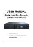
Download DVR Server Manual
Transcript
DVR Server Manual Version 052308 © 2008 Aventura Technologies DVR Server Manual © 2008 Aventura Technologies All rights reserved. No parts of this work may be reproduced in any form or by any means - graphic, electronic, or mechanical, including photocopying, recording, taping, or information storage and retrieval systems - without the written permission of the publisher. Products that are referred to in this document may be either trademarks and/or registered trademarks of the respective owners. The publisher and the author make no claim to these trademarks. While every precaution has been taken in the preparation of this document, the publisher and the author assume no responsibility for errors or omissions, or for damages resulting from the use of information contained in this document or from the use of programs and source code that may accompany it. In no event shall the publisher and the author be liable for any loss of profit or any other commercial damage caused or alleged to have been caused directly or indirectly by this document. Printed: July 2008 Contents I Table of Contents Part I Introduction Start up 2 ................................................................................................................................... 2 Part II Getting Used to Main Interface 4 Main Interface................................................................................................................................... Button's Functions 5 Lock DVR Button .......................................................................................................................................................... 5 Minimize Button .......................................................................................................................................................... 5 Exit Button .......................................................................................................................................................... 5 Settings Button .......................................................................................................................................................... 5 Playback Button .......................................................................................................................................................... 5 Chat Button .......................................................................................................................................................... 5 Write Log Button .......................................................................................................................................................... 5 System Log Button .......................................................................................................................................................... 6 Motion And Mask Button .......................................................................................................................................................... 6 Split Screen Button .......................................................................................................................................................... 6 E-map Button .......................................................................................................................................................... 6 Options Button.......................................................................................................................................................... 6 Manual Record.......................................................................................................................................................... Button 6 Sequence Button .......................................................................................................................................................... 6 30 Second Record Button .......................................................................................................................................................... 6 Capture Screen Button .......................................................................................................................................................... 6 Main Interface................................................................................................................................... Control Tabs 7 Network .......................................................................................................................................................... 8 PTZ Control .......................................................................................................................................................... 9 Color - Audio.......................................................................................................................................................... 10 Matrix-Display.......................................................................................................................................................... 11 Output Control .......................................................................................................................................................... 12 Tracking Time, ................................................................................................................................... Date, Free Space, and Camera 13 Knowing the................................................................................................................................... Video Status 13 Recording Status .......................................................................................................................................................... 13 Part III Settings (System Configuration) 15 System Configuration ................................................................................................................................... 16 System Setup.......................................................................................................................................................... 17 Number of......................................................................................................................................................... Channels 17 Sensor Inputs ......................................................................................................................................................... 17 Alarm Outputs ......................................................................................................................................................... 17 Use Audio......................................................................................................................................................... Monitoring 17 Use E-Map ......................................................................................................................................................... 18 Camera Sequencing ......................................................................................................................................................... Interval (Secs) 18 Sensor/Alarm ......................................................................................................................................................... Port 18 Main Recording ......................................................................................................................................................... Disk 18 Save Log......................................................................................................................................................... 18 When Disk ......................................................................................................................................................... is Full 18 Date Format ......................................................................................................................................................... 19 © 2008 Aventura Technologies II DVR Server Manual Auto Logout ......................................................................................................................................................... 19 Sensor/Alarm ......................................................................................................................................................... Device 19 Time Format ......................................................................................................................................................... 19 Alarm Beep ......................................................................................................................................................... 19 Network Setup .......................................................................................................................................................... 20 NVR Client ......................................................................................................................................................... Connection 20 Port for NVR ......................................................................................................................................................... Client 20 Remote Buffer ......................................................................................................................................................... Priority 20 Automatic......................................................................................................................................................... Alarm Notification Client IP 20 Alarm Send ......................................................................................................................................................... Port 21 Web Server ......................................................................................................................................................... Port 21 Use DNS ......................................................................................................................................................... 21 Local Host ......................................................................................................................................................... Name 21 DNS Server ......................................................................................................................................................... IP 22 DNS Connection ......................................................................................................................................................... Port 22 Interval Connection ......................................................................................................................................................... Time 22 How it works ......................................................................................................................................................... 23 Exit and Reboot Mode Setup .......................................................................................................................................................... 24 Exit Option ......................................................................................................................................................... 24 Auto Reboot ......................................................................................................................................................... Setup 25 IP Camera Configuration ................................................................................................................................... 26 Display List .......................................................................................................................................................... 27 Camera Name.......................................................................................................................................................... 27 Camera Type .......................................................................................................................................................... 27 IP Address .......................................................................................................................................................... 27 Device Model.......................................................................................................................................................... 27 Connection Port .......................................................................................................................................................... 27 Login User Name .......................................................................................................................................................... 27 Login Password .......................................................................................................................................................... 27 Add Button .......................................................................................................................................................... 28 Modify Button.......................................................................................................................................................... 28 Delete Button.......................................................................................................................................................... 28 Analog Camera ................................................................................................................................... Configuration 29 Camera Setup.......................................................................................................................................................... 30 Select a Camera ......................................................................................................................................................... 30 Camera Description ......................................................................................................................................................... 30 Camera Type ......................................................................................................................................................... 30 Enable This ......................................................................................................................................................... Camera 30 NVR Frame ......................................................................................................................................................... Rate 31 Bit Rate ......................................................................................................................................................... 31 Image Size ......................................................................................................................................................... 31 NVR Image ......................................................................................................................................................... Size 31 Image Quality ......................................................................................................................................................... 31 Frame Rate ......................................................................................................................................................... 32 NVR Quality ......................................................................................................................................................... 32 OSD Contrast/ ......................................................................................................................................................... Position 32 Watermark ......................................................................................................................................................... Bitmap File 32 Recording......................................................................................................................................................... Days 32 Maximum......................................................................................................................................................... File Size(MB) 32 Copy Setup ......................................................................................................................................................... to 33 Scheduled Recording Setup .......................................................................................................................................................... 33 Selected Group ......................................................................................................................................................... 33 Selected Camera ......................................................................................................................................................... 33 © 2008 Aventura Technologies Contents III Pre-Event......................................................................................................................................................... Record 33 Post Record ......................................................................................................................................................... Time 34 Record Audio ......................................................................................................................................................... 34 Recording......................................................................................................................................................... Schedule 35 Sensor Configuration ................................................................................................................................... 36 Sensor Setup.......................................................................................................................................................... 37 Select Sensor ......................................................................................................................................................... 37 Sensor ......................................................................................................................................................... 37 Sensor Description ......................................................................................................................................................... 37 Activate PTZ ......................................................................................................................................................... Preset 37 Play Alarm ......................................................................................................................................................... Sound 37 Link to PTZ ......................................................................................................................................................... 37 Sensor Group.......................................................................................................................................................... Setup 38 Group ......................................................................................................................................................... 38 Sensor Type ......................................................................................................................................................... 38 Write Alarm ......................................................................................................................................................... Log 38 Alarm Action ......................................................................................................................................................... After It Times-Out 38 Sensor Input ......................................................................................................................................................... 39 Start Recording ......................................................................................................................................................... Cameras 39 Trigger Alarms ......................................................................................................................................................... 39 PTZ & Alarm ................................................................................................................................... Configuration 40 PTZ Setup .......................................................................................................................................................... 41 Selected Camera ......................................................................................................................................................... 41 PTZ Port ......................................................................................................................................................... 41 PTZ Protocol ......................................................................................................................................................... 41 PTZ Address ......................................................................................................................................................... 41 PTZ Baud......................................................................................................................................................... Rate 41 PTZ Position ......................................................................................................................................................... 42 Alarms Setup.......................................................................................................................................................... 42 Select Alarm ......................................................................................................................................................... Port 42 Alarm Description ......................................................................................................................................................... 42 Motion Detected ......................................................................................................................................................... 42 Send Alarm ......................................................................................................................................................... to Client 43 Play Alarm ......................................................................................................................................................... Sound 43 Trigger DO ......................................................................................................................................................... Output 43 E-Mail Configuration ................................................................................................................................... 44 STMP Setup .......................................................................................................................................................... 45 Outgoing ......................................................................................................................................................... SMTP Server 45 SMTP Port ......................................................................................................................................................... 45 Authorized ......................................................................................................................................................... Type 45 Log-In User ......................................................................................................................................................... Name 45 Log-In Password ......................................................................................................................................................... 45 Email Notification Setup .......................................................................................................................................................... 46 Send To Email ......................................................................................................................................................... 46 Copy To Email ......................................................................................................................................................... 46 Sender Email ......................................................................................................................................................... 46 Email Screenshot ......................................................................................................................................................... As Attachment 46 Send Notification ......................................................................................................................................................... from Cameras 47 Send Notification ......................................................................................................................................................... from Sensors 47 Matrix & Display ................................................................................................................................... Configuration 48 Digital matrix.......................................................................................................................................................... Setup 49 Matrix Group ......................................................................................................................................................... 49 Video Out......................................................................................................................................................... Port 49 © 2008 Aventura Technologies IV DVR Server Manual Video Out......................................................................................................................................................... Standard 49 Video Switch ......................................................................................................................................................... Interval 49 Video Split ......................................................................................................................................................... Mode 50 Video Window ......................................................................................................................................................... 50 Display Setup.......................................................................................................................................................... 51 Display Group ......................................................................................................................................................... 51 Video Split ......................................................................................................................................................... Mode 51 Video Window ......................................................................................................................................................... 51 User Configuration ................................................................................................................................... 52 Users Management .......................................................................................................................................................... 53 Use Password ......................................................................................................................................................... Protection 53 Users List......................................................................................................................................................... 53 User Name ......................................................................................................................................................... 53 Full Name......................................................................................................................................................... 53 Password......................................................................................................................................................... 53 Confirm Password ......................................................................................................................................................... 54 Rights Level ......................................................................................................................................................... 54 User Rights Setup .......................................................................................................................................................... 54 View Camera ......................................................................................................................................................... 54 Playback ......................................................................................................................................................... Camera 54 User Access ......................................................................................................................................................... Rights 55 Setup Rights ......................................................................................................................................................... 55 Add User Button .......................................................................................................................................................... 55 Modify Button.......................................................................................................................................................... 55 Delete User Button .......................................................................................................................................................... 55 Part IV Functions and Features Playback 57 ................................................................................................................................... 57 Playback Mode .......................................................................................................................................................... 58 Date Panel ......................................................................................................................................................... 58 Camera Panel ......................................................................................................................................................... 59 File Panel......................................................................................................................................................... 60 Playback ......................................................................................................................................................... Controls 61 Search Images ......................................................................................................................................................... 62 Backup Video ......................................................................................................................................................... 64 Splits ......................................................................................................................................................... 71 Play All ......................................................................................................................................................... 71 Stop All ......................................................................................................................................................... 71 Playback Current Camera's last Recorded File .......................................................................................................................................................... 72 Playback to TV Monitor .......................................................................................................................................................... 73 Chat ................................................................................................................................... 75 Write Log ................................................................................................................................... 76 System Log ................................................................................................................................... 77 Motion and Mask ................................................................................................................................... 78 Split Screen ................................................................................................................................... 79 E-Map ................................................................................................................................... 80 E-Map Layers.......................................................................................................................................................... Setup 81 Option ................................................................................................................................... 82 © 2008 Aventura Technologies Contents © 2008 Aventura Technologies V Part I Introduction 2 Introduction Thank you for purchasing Aventura’s DVR system. This operation manual is designed to introduce you on how to setup Aventura’s DVR system, and explain each function of the DVR in order to use the system effectively. Operators of the Aventura DVR system should go through this manual thoroughly, prior to installing, or using the system. *NOTE: If you are reading the manual with Adobe Reader. Please pay especial attention to the blue hyperlink text. These text are links that bring you directly to the information and explanation of a specific topic. If you are using the printed copy of this manual please refer to page number on the manual for information and explanation of a specific topic. Start up Before you press the DVR power button, please check that all the connections are firmly attached and that cables are not loose. Please refer to connection diagrams. Press the DVR system power button, the power LED turns on, the main window will display shortly (depending on how many channels you have). If the DVR Server automatic startup shortcut has been deleted or is no longer functioning, please double click the DVR Server icon on the Windows Desktop. © 2008 Aventura Technologies Part II Getting Used to Main Interface 4 Getting Used to Main Interface Main Interface The above is the Main interface. This is the first screen you will see after you runs the DVR application from your desktop. Please take a minute or two to get to know the main Interface. It will be helpful for later use of this application. NOTE: The Number of video window on your system may vary. The total of Video Window is determine by the Channel Card that is install in your DVR. For this particular example here, it is install with 4 channel Card. © 2008 Aventura Technologies 5 DVR Server Manual Main Interface Button's Functions Main Interface Button Lock DVR Button Lock DVR button is located on the bottom left of the Main Interface. By clicking the Lock DVR button, it locks the keyboard and mouse preventing unauthorized users to operate the DVR system. This will only function if password protection is enabled. See Use Password Protection on page 35 for instruction to enable password protection. Minimize Button Minimize button is located on the bottom left of the Main interface below Lock DVR button. Minimize Button minimizes the main software window to the windows taskbar. Exit Button Exit button is located on the bottom left of the Main interface next to the Lock DVR button and Minimize button. Clicking on the Exit button you will be prompted with a dialog box to confirm exit. Click "OK" to exit DVR and click "Cancel" to resume. Settings Button Setting Button is located bottom left of the Main interface next to "Exit button". Click on the Settings button to go to the DVR System set-up. Please see also Settings (System Configuration) on page for set-up instructions. Playback Button Playback Button is located bottom left of the Main interface next to "Settings button". When Playback button is clicked a sub menu will appears. The option on the sub menu are "Playback Mode", "Playback current camera's last recorded file", and "Playback to TV monitor". Playback Mode allows users to enter playback mode and search for recorded video/ audio. Please see also Playback Mode on page for more detail. Chat Button Initiates a dialog box to connect to a remote client, or DVR server to chat live over IP. Please see Chat for more detail. Write Log Button Writes a Working Log. This write log is designate for operator shift use. Please see also Write Log for more detail. © 2008 Aventura Technologies Getting Used to Main Interface 6 System Log Button System Log is an automatically generate record. It keep track of all the events that has happen in the DVR system. Please see also System Log for more detail. Motion And Mask Button Used to set up the built-in motion detection. Please see also Motion and Mask for detail. Split Screen Button Changes the window display mode of the main screen. Please see also Split Screen for more detail. E-map Button Displays an electronic map the show the blueprint of the business camera system layout. Please see also E-map for more detail. Options Button Opens a my computer file/directory viewer in windows. Please see also Option for more detail. Manual Record Button Allows users to record manually any camera regardless of its recording mode. Click the button again to stop recording. Sequence Button Enables the DVR to sequence through all channels. Click again to stop. 30 Second Record Button This button triggers the recording of all cameras for a 30 second period. This will force all cameras to record for 30 seconds, regardless of its recording mode. This function is useful in an emergency where quick action is required. Capture Screen Button Capture Screen allows the user to save a still image of a selected camera in live mode onto the hard disk. The image can later be reviewed, printed, and emailed. (Viewing Captured Screen) © 2008 Aventura Technologies 7 DVR Server Manual Main Interface Control Tabs Control Tabs Main Interface Control Tabs are located on the left of Main interface. Their are Network Panel Tab, PTZ Control Tab, Color and Audio Tab, Matrix and Display Tab, and Alarm Control Tab. Every tab have its own corresponding window. The window is called "Main Control Tab Window". This window is on the left of the Control Tabs. Network Tab -- See page 9 PTZ Control Tab -- See page 10 Color-Audio Tab -- See page 11 Matrix- Display Tab -- See page 12 Output Control Tab -- See page 13 © 2008 Aventura Technologies Getting Used to Main Interface Network Panel Tab Network Network Tab Window displays network configurations of the DVR server. The information that display in Network Tab Window includes Network Adapter, IP Address, Subnet Mask, as well as Net Gate and Sites Connected. Network Adapters Shows the name of the Adapter that is being use. IP Address Shows the IP Address of the DVR. Subnet Mask Shows the network setting, generally 255.255.255.0 Net Gate Shows the connected router address. Sites Connected Shows you the IP address of any clients connected remotely. © 2008 Aventura Technologies 8 9 DVR Server Manual PTZ Control Tab PTZ Control PTZ (Pan/Tilt/Zoom) Control Tab Window: Relays Button Relay (On/Off): Controls the PTZ camera’s internal relay (relay 1), or the decoders relay (relay 1). Used to turn on a light or control an access gate. Wipers Button Wiper (On/Off): If using the PTZ camera’s corresponding wiper control relay, this toggles the relay/wiper on and off. IRIS Control Iris+: Overrides the PTZ cameras auto-iris and allows one to brighten the image. Iris- : Overrides the PTZ camera’s auto-iris, closing it, and darkening the image. Focus Control Focus +: Overrides the auto-focus setting of the PTZ camera, allowing one to further focus the image. Focus- : Overrides auto-focus in the camera and allows the user to make adjustments to camera focus. Zoom Control Zoom +: Zooms in Zoom - : Zooms out Pan Control Auto Pan: Pressing this button initiates an automatic tour of all preset positions by the connected PTZ camera. By pressing and holding these buttons, the PTZ camera can moved up, down, right, and left. Speed Dome Button Speed Dome: Turns the preset control panel on/off. There are 16 preset points for the speed dome on the top. There is a numeric keypad on the bottom. To Set Preset Points For Your Camera: - Position your camera using the controls where you would like a preset point to be saved Click speed dome at the top to enter speed dome options In the number pad in the bottom (type a number 1-16) which will be your preset point and hit Set. You will now see the number you selected turn blue in the available presets directly above the number entry. Simply clicking this number will bring the camera to the point you set. You can set up to 16 different points for the camera to remember and overwrite old points. © 2008 Aventura Technologies Getting Used to Main Interface Color - Audio Tab Color - Audio Color-Audio Tab Window adjusts the video image and recording volume of the selected channel. This also affects the live view of the video feed. The adjust control includes Brightness Control, Contrast Control, Hue Control, Saturation Control, Volume Control. Brightness Control Slid the Adjust Slider above the Brightness to adjust brightness. Slid the Adjust Slider up increase the brightness. Slid the Adjust Slider down decrease the brightness. Contrast Control Slid the Adjust Slider above the Contrast to adjust contrast. Slid the Adjust Slider up increase the contrast. Slid the Adjust Slider down decrease the contrast. Hue Control Slid the Adjust Slider above the Hue to adjust color. Saturation Control Slid the Adjust Slider above the Saturation to adjust amount of gray in the color. Slid the Adjust Slider up increase saturation. Slid the Adjust Slider down decrease the saturation. Volume Control Slid the Adjust Slider above the Volume to adjust volume. Slid the Adjust Slider up increase the volume. Slid the Adjust Slider down decrease the volume. Hints & Tips Brightness Contrast Hue Saturation Click on these button above bring you back to default adjustment. Volume Click on this button put you to mute. Click it once again to resume. © 2008 Aventura Technologies 10 11 DVR Server Manual Matrix-Display Tab Matrix-Display Matrix - Display Tab Window includes: the matrix group and the display group. Each group includes: 16 numeric buttons; Each button denotes one type of matrix or display. This can set up in “System Setup”. © 2008 Aventura Technologies Getting Used to Main Interface Output Control Tab Output Control Output Control manually controls sensor/alarm relays. If your DVR is not equipped with a sensor/alarm box or card this feature will not work. © 2008 Aventura Technologies 12 13 DVR Server Manual Tracking Time, Date, Free Space, and Camera Information panel Information Panel is located on the bottom of the main Interface and it is next to the "Option Button". Information panel shows current date, current time, day of the week, free hard drive space, and which camera was being selected. NOTE: The format to display Date and Time can be change under "System Set-up". For information on how to Set-up the Date and Time see "Setting (System Configuration)" on page. Knowing the Video Status Status Icons Recording Status The recording status is shown in the upper right hand corner of each active video window. The meaning of the status icons are as follow: If it shows a clock icon, the system is recording normally. If it shows a cassettes tape icon, the system is recording manually. If it shows a running figure icon, the system is recording in motion detection mode. If it shows a yellow Lightning bolt icon, the system is recording in sensor detection mode. © 2008 Aventura Technologies Part III 15 DVR Server Manual Settings (System Configuration) Default Setting Menu Settings Button on the Main Interface open up the "Setting" window below. There are seven different types of configurations in the DVR "Setting" window, the default configuration is the System configuration. There are three Setup on this configuration window. On the top of this window is System Setup. Following the System Setup is the Network Setups. Then is the Exit and Reboot Mode Setup. List of the seven configuration: System Configuration Analog Camera Configuration Sensor Configuration IP Camera Configuration Email Configuration PTZ & Alarms Configuration User Configuration Digital Matrix and Display Configuration © 2008 Aventura Technologies Settings (System Configuration) System Configuration System Setup © 2008 Aventura Technologies 16 17 DVR Server Manual System Setup Number of Channels "Number of Channels" is located upper left corner of the System Setup section. This displays the total number of channels available on your DVR. The total numbers of channel is based on the number of cards installed on the system, and cannot be manually changed in the software. Sensor Inputs "Sensor Input" is next to "Number of Channels" in the System Setup section. This displays the total number of sensors available on your DVR. Total numbers of sensor input is based on the number of available digital inputs installed on the system, and cannot be manually changed in the software. Example of a Sensor: PIR Motion Detector, Temperature Sensor. Alarm Outputs "Alarm Outputs" is next to "Sensor Inputs" it is located upper right corner of the System Setup section. This displays the total number of Sensor Ouput available on your DVR. Total numbers of sensor output is based on the number of available digital output installed on the system, and cannot be manually changed in the software. Example of a Sensor Output: Alarm, Siren, Door lock. Use Audio Monitoring "Use Audio Monitoring" is located below "Number of Channels" in the System Setup section. This is an option for you to Enable/Disable audio-monitoring. Select "Yes" to enable. Select "No" to disable" © 2008 Aventura Technologies Settings (System Configuration) 18 Use E-Map "Use E-Map" is next to "Use Audio Monitoring" in the System Setup section. This is an option for you to Enable/Disable E-Map. Select "Yes" to display Electronic Map, or select "No" not to display Electronic Map. See E-Map button. Camera Sequencing Interval (Secs) "Camera Sequencing Interval" is next to "Use E-Map". This is to set the sequencing interval time between cameras in seconds. see Sequencing button. Sensor/Alarm Port "Sensor/Alarm Port" is located below "Use Audio Monitoring". Select sensor/alarm COM port. If you do not use the alarming input, you can close this function to save system resources. NOTE: The COM port use for Senor/Alarm must be different from the COM port use for PTZ. See PTZ section Main Recording Disk "Main Recording Disk" is next to "Sensor/Alarm Port". This sets the location which all of the recording stores. the main recording storage drive. The DVR will record on additional hard drive disks in alphabetical order. Drive letters prior to the one selected will not be used to record, and will not be checked by the system. Windows mapped network drives will also be used in the same alphabetical order. For example… if D:\ is selected, when that drive is full it will proceed to check if other drives starting with E:\ have space available to store data. It will not use C:\ Drive. Save Log "Save Log" is next to "Main Recording Disk". This is use to set the maximum number of days to save the Log file. After the selected number of day Log files will be cleared. When Disk is Full "When Disk is Full" is located under "Sensor/Alarm Port" This is use to set the recording mode when there is not enough free hard drive space. If “Overwrite Data” is selected, the DVR system will auto-delete the oldest recorded video when there is not enough space. If “Stop Recording” is selected the DVR system will stop recording and give a warning message. © 2008 Aventura Technologies 19 DVR Server Manual Date Format "Date Format" is located next to "When Disk is Full". This is use to sets the date format for the date on the "On-Screen Display" and the date on the "Information Panel". Auto Logout " Auto Logout" is located next to "Date Format". This is use to set the automatic log-out time. For example: If you set 30 sec the system will Log you out in 30 sec. Sensor/Alarm Device "Sensor/Alarm Device" is located under "When Disk is Full". This is use for to selects the alarm device type. Time Format "Time Format" is located next to "Sensor/Alarm Device". This is use to set the time format for the "On-Screen Display" and "Information Panel". Alarm Beep "Alarm Beep" is located under " Sensor/Alarm Device". This is use to “Disable” or “Enable” beep sound when there is an alarm. Select "No" to disable. Select "Yes" to enable. © 2008 Aventura Technologies Settings (System Configuration) 20 Network Setup NVR Client Connection "NVR Client Connection" is located upper left corner of Network setup section. This is use to allow remote connection from the NVR client over the network. Select "Enable" to allow remote connection. Select "Disable" to ban remote connection. Port for NVR Client "Port For NVR Client" is next to "NVR Client Connections" This is use to set the remote client connection port. NOTE: This port must be forwarded on your router. See your router's manual for more information. Remote Buffer Priority There are three options: 1. Realtime 2. Normal 3. Smooth (Larger buffer) Automatic Alarm Notification Client IP "Automatic Alarm Notification NVR IP" is located under "NVR Client Connection". This is use to assign a network client to receive a message when there is an alarm. The alarmed channel's video will auto-display in the client software. NOTE: The alarm auto-connection to IP is used to trigger the alarm automatically. The system will check to see if the client is connected to the system with an IP address using sensor, normal, or motion recording. If there is no connection, it will try to connect with it through Port 5300(default). It will continue doing this until the connection is established, so please ensure that your client’s program is connected, Port 5300 is open, and the network is in proper condition. If not, the system will not be stable . © 2008 Aventura Technologies 21 DVR Server Manual Alarm Send Port "NVR Alarm Port" is next to "Automatic Alarm Notification NVR IP". This is use to set connecting port to send the alarm. Web Server Port "Web Server Port" is next to "NVR Alarm Port". This is use to set up the web server port in order to watch video remotely through Internet Explorer. The default web server port is 8000, and if you need to change it you should add the port number when visiting the server’s video URL through Internet Explorer. (For example: http://69.112.24.127:8000) NOTES ON VIEWING THROUGH INTERNET EXPLORER: Active X Controls Need to be Enabled! (In Internet Explorer Click Tools>Click Options> Go to Security Tab>Click Custom Level>Scroll down to the entry Download unsigned Active X Controls and change to ENABLE) 1. If the connection is successful, there will be a four partition blue window. However, if the connecting fails it could be for one of the following reasons: The web server port is being used by another program. Your computer was not able to download the Active X player. The reason may be that the security setting on your computer is too high or a firewall is blocking it. Please allow Active X Controls to be downloaded in order to use this function. 2. If it shows a blue image window but has no response when you press the connect button or Internet Explorer comes up with an error, the reason may be that your computer has installed an old version of the Active x control. Please find these files on your computer’s system path (C:\Winnt\System32): “dvrnet.dll, netchannel.dll, HikplayM4.dll, netcision.ocx, M4play.dll”. Delete them and exit. Then enter the Internet Explorer client and attempt to re-connect again to re-download. Make sure all pop-up blockers are disabled – Only Internet Explorer is supported – Please see client manual for more information and troubleshooting tips with viewing through Internet Explorer. Use DNS "Use DNS" is located under "Automatic Alarm Notification NVR IP". This is use for enable or disable DNS. Select "Enable" to support dynamic IP. Select "Disable" not to support dynamic IP. Local Host Name "Local Host Name" is next to "Use DNS". This is use for input the name description for the DNS Server identification. © 2008 Aventura Technologies Settings (System Configuration) 22 DNS Server IP "DNS Server IP" is located under "Use DNS". This is use to fill in the DNS server host IP. DNS Connection Port "DNS Connection" is next to "DNS Server IP". The DNS server host port is provided to connect to the DNS software. Interval Connection Time "Interval Connection Time" is next to "DNS Connection Port". This is use to set the Automatic Interval Connection Time. © 2008 Aventura Technologies 23 DVR Server Manual How it works 1. If your DVR has a dynamic IP, you should configure your DVR system as follows: 2. DNS server will receive your DVR’s domain name and the current IP address 3. Clients receive the DVR’s current IP address through the DNS server according to the DVR’s domain. 4. Clients visit the DVR through the IP address they receive from the DNS server. © 2008 Aventura Technologies Settings (System Configuration) 24 Exit and Reboot Mode Setup Here is where to set-up the Exit and Reboot mode. NOTE: For stability purposes, we recommend to use "Auto-Reboot" so the system will run more smoothly. Exit Option Exit to Windows This is the first option in the Exit Mode set up. If this is selected, exit the DVR application will close the DVR application only. Exit And Shutdown This is the second option in the Exit Mode set up. If this is selected, exit the DVR application will also shut-down the computer. Auto ShutDown This is the last option in the Exit Mode set up. If this is selected, system will exit and shutdown automatically when it is the set time. © 2008 Aventura Technologies 25 DVR Server Manual Auto Reboot Setup Auto Reboot Date To set a reboot date, select the auto-restart days from this list above. A Blue number grid means the day is selected. A White number grid means the day is not Selected. NOTE: The example above have none of the days selected meaning the system will not perform reboot in any day. Auto Reboot Time In order for the system to perform auto reboot. You will also need to set the reboot time. NOTE: The time format for this system is 24hr. © 2008 Aventura Technologies Settings (System Configuration) IP Camera Configuration IP Camera Set-up © 2008 Aventura Technologies 26 27 DVR Server Manual Display List This table shows a list of all the IP cameras that have been set up to be used with the DVR. Camera Name Enter a name for the camera. This can be anything and it is used for reference only. Camera Type Select the manufacturer of the IP Camera. IP Address Enter the IP address of the camera. (See camera’s user manual) Device Model Select the camera’s model for your camera. Connection Port Enter the connection port of the camera. (See camera’s user manual). If you are using an external network IP the port must be forwarded on your router. See your router’s manual for instructions. Login User Name Enter the login name for the camera. (See camera’s user manual) Login Password Enter the login password for the camera. (See camera’s user manual) © 2008 Aventura Technologies Settings (System Configuration) Add Button Adds a camera to the list. Modify Button Modifies the selected camera's settings using the current setting on the screen. Delete Button Deletes the selected camera from the list. © 2008 Aventura Technologies 28 29 DVR Server Manual Analog Camera Configuration Analog Camera Set-up © 2008 Aventura Technologies Settings (System Configuration) 30 Camera Setup Select a Camera To setting up a camera, select a camera from the drop-down list to set each of the following parameters. Each camera need to be set-up individually. NOTE: You can also use the "Copy Setup to" to copy the setting of one camera to another. Please see "Copy Setup to" for how to copy one camera's Parameters to another. Camera Description Input a custom camera description for easy identification. (For example: The location of the camera) The description enter here will be display on the On-Screen-Display (OSD) in the main interface. Camera Type Select the camera type from the drop-down list. There are 2 types of cameras: PAL and NTSC. Select one according to your location. For example, for camera type in North America you will select NTSC because in North America NTSC is the standard camera type. NOTE: Auto camera type detection is built-in on the system. If you do not have knowledge of the camera type in the area please do not change the camera type manually. Enable This Camera "Enable This Camera" is for enable or disable selected camera. When a camera is enable Video loss detection will be active. After the selected camera is enabled, any physically damage to the connected cable, or the damage to the camera trigger video loss alarm. NOTE: Anytime that you are using less cameras than the DVR can handle, many of them will not have pictures, and an alarm will appear and beep to tell you some video information is missing. If you set the cameras with no picture as “disabled” the alarm will disappear. When you want to use them later, just set them as enabled. © 2008 Aventura Technologies 31 DVR Server Manual NVR Frame Rate "NVR Frame Rate" is use to set the display frame rate for the cameras on the client side. Select from 1 to 30 frames per second. When the image size was selected to be D1, the frame rate should be set to 7-15 frames per second. Otherwise, during playback, the video will appear glitchy. Bit Rate Sets record mode. Variable Bit Rate (VBR) or Constant Bit Rate (CBR) Recording. VBR allows each frame to go up or down, depending on the image complexity, activity, and color. CBR will throttle the bit rate to a fixed amount, regardless of the image activity. In many cases, this limits detail (resolution). The benefit of CBR is the ability to accurately estimate the total amount of storage needed. Image Size Set the image resolution. There is an option for “D1 Auto F” which each channel can be set to, but this “D1”is a not a true “D1”. It is actually 4CIF digitally enlarged to D1. The system will select frame rate automatically (usually 12-15 frames per second). NVR Image Size Select image size to be transmitted to the client side. When “Same as Rec.” is selected it will use the same settings as local recording. Image Quality This is to be use to set the quality of the image to be recorded. Lower quality use less hard drive space. Higher quality use larger hard drive space. Just as it is shown in the table below. Image Quality Image Quality Lowest Medium Best Recording Environment Used Disk Space (/com/hour) Low action About 45mb High action About 95mb Low action About 70mb High action About 180mb Low action About 160mb High action About 320mb © 2008 Aventura Technologies Settings (System Configuration) 32 Frame Rate Sets the recording rate for the selected camera in Frames per Second (fps). Select from 1 to 30 fps. When the image size was selected to be D1, the frame rate should be set to 12-15 frames, otherwise, during playback, the video will appear glitchy. NVR Quality Sets the quality of the image to be sent to the client side. OSD Contrast/ Position This is use to set the On-Screen Display (OSD) Contrast & position. "OSD Contrast" is to be use to set the contrast of the OSD. There is an “Auto” option. This option makes the OSD contrast from the background automatically. Which is in another word, to adjust the contrast of the date and time show on the window easier to read. "OSD Position" is use to adjust the position of the OSD. Which is in another word, to sets the position where the date shows up on the window. Watermark Bitmap File Watermark feature: Select a .bmp file. It should be less than 128 X 128 pixels. It overlaps the video. Recording Days This option allows the operator to determine how long the recorded data of each camera should be kept in the system. The maximum duration for on-line storage is 120 days. The system operator can select a definite number of days, or “auto” mode. If “Auto” is selected, the systems will auto-delete the oldest recorded data when there is not enough space. NOTE: If there is not enough hard drive space, the system will delete the recorded data according to the selected saving days of each camera. Maximum File Size(MB) Sets the maximum size for the recorded video clips saved on the hard drive. For easy backup, do not set a large file size. The default is recommended. NOTE: The maximum file size is by MB. Input a value in the box with your keyboard. For example: If you input 30, a new file will be created when the video reaches 30MB. The allowed range for your input value is from 2-50. © 2008 Aventura Technologies 33 DVR Server Manual Copy Setup to The "Copy Setup to" is use to copy one camera setup to another camera. Copy a setup just select from the list the number of a camera you want to copy the current setup. Then click the copy button. NOTE: To copy settings of selected camera to all other cameras select ALL. Then click copy button. Scheduled Recording Setup "Scheduled Recording Setup" is to arrange cameras into different recording groups. These groups will share their recording modes and schedule. NOTE: Same camera can not appear in two different group. If you setup groups with conflicting cameras, then the previous setup for that camera will be replaced with the latest setup. Selected Group To begin, select a group in the drop down list. Selected Camera Then, select the cameras that you would like to group together. A blue color number grid means the camera is Selected. A white color number grid means the camera is Not Selected Pre-Event Record Select the beginning time to record when there is an alarm. When the DVR system is in Motion Detect mode or Sensor Detect mode, it can record video before the alarm is triggered. © 2008 Aventura Technologies Settings (System Configuration) 34 Post Record Time Select the end time of record when there is an alarm. When the system is in Motion Detect mode or Sensor Detect mode, it can record video after the alarm stops. Record Audio Select "Yes" to record audio. Select "No" not to record audio. © 2008 Aventura Technologies 35 DVR Server Manual Recording Schedule This is a mode button and there are five modes. Every one of the block is 30 minute recording period. Getting to Know the Recording Schedule Normal Record Mode (teal): In this mode the DVR System is always recording video. (For example: Normal record schedule on the above set-up is Mon-Fri 8:00 am-12:00 pm and from 2:00 pm- 5:30 pm for all cameras that has been selected.) Sensor Record Mode (red): In this mode the DVR System begins to record video only when there is a sensor alarm. (For example: Sensor record schedule on the above set-up is Mon-Fri 12:30pm-1:30pm for all cameras that has been selected.) NOTE: The time setting must correspond with Check Sensor settings in SENSOR SETUP, otherwise it will not work properly. Motion Record Mode (blue): In this mode the DVR System begins to record video only when it detects a moving object. (For example: Motion record schedule on the above set-up is Mon-Fri 12:00am-7:30am for all cameras that has been selected.) Motion or Sensor Record Mode (yellow): In this mode DVR System begins to record video either an alarm was trigger or motion has been detected. This mode combines Sensor Record Mode and Motion Record Mode functions.(For example: Motion or Sensor record schedule on the above set-up is all day Sun, Sat and on Mon-Fri 6:00pm-11:30pm for all cameras that has been selected.) Do Not Record Mode (gray): In this mode the DVR System does not record video. Instruction for Set Up the Recording Schedule Step 1: Click on a desired recording mode button. Step 2: Select the desired time and day of the week by clicking the schedule diagram. Step 3: Click the Save & Return button to save the schedule. Hints &Tips: Click and hold down the mouse can select a larger areas. Click the blank block above "SUN" changes all the schedule to one mode that is currently being selected at the time. Click one of the Day set the day schedule to one of the mode that is currently being selected at the time. Click one of the Hours set the hour schedule on every day to one mode that is currently being selected at the time. © 2008 Aventura Technologies Settings (System Configuration) Sensor Configuration Sensor setup © 2008 Aventura Technologies 36 37 DVR Server Manual Sensor Setup Select Sensor To set the parameters for a sensor, select the sensor from the drop-down list. Sensor To enable this sensor port select "Yes". To disable select "No". Sensor Description To make a sensor easier to be identify, enter a description for the sensor. Activate PTZ Preset Select a PTZ preset Number. The PTZ camera will automatically move to this preset number when the sensor is triggered. NOTE: For this to work, requires a PTZ camera installed. Play Alarm Sound Select a ".wav" sound for a sensor. When there is an alarm, the selected sound will play. Link to PTZ Select which PTZ camera responds when the sensor input is triggered. A blue color number grid means the camera is Selected. A white color number grid means the camera is Not Selected © 2008 Aventura Technologies Settings (System Configuration) 38 Sensor Group Setup Sensor group setup is very similar to the camera recording Setup. "Sensor Group Setup" is to arrange sensor into different setting groups. These groups will share their setting and schedule. NOTE: Same sensor can not appear in two different group. If you setup groups with conflicting sensor, then the previous setup for that sensor will be replaced with the latest setup. Group To begin, select a group. Sensor Type Select Normally closed (N/C) or Normally Open (N/O) alarm type. Write Alarm Log Select whether to write an alarm log or not. If you select "Yes" system automatically writes a log when the alarm is triggered. If you select "No" system will not writes log when the alarm is triggered. Alarm Action After It Times-Out Select an alarm mode after an alarm times-out. “Stop Immediately” means the system stops the alarm immediately after the sensor is off. “Do Not Stop” means the system does not stop an alarm after the sensor is off. “Wait” means the system will stop the alarm after the time you set. © 2008 Aventura Technologies 39 DVR Server Manual Sensor Input Add sensor to the selected group. A blue color number grid means the sensor is Selected. A white color number grid means the sensor is Not Selected Start Recording Cameras Select which cameras respond with this sensor group. They will start recording and will auto connect to the remote network client when there is an alarm. A blue color number grid means the camera is Selected. A white color number grid means the camera is Not Selected Trigger Alarms Add alarm devices (alarm output) to this group. For example: siren and light. All connecting devices will send an alarm message when there is an alarm. A blue color number grid means the alarm is Selected. A white color number grid means the alarm is Not Selected Schedule Setup (Example for this image) Check Sensor (red): The DVR system responds with a sensor. Do Not Check Sensor (gray): The DVR System does not respond to the sensor. NOTE: If you setup the groups with a conflicting camera, then only the last setup will function. © 2008 Aventura Technologies Settings (System Configuration) PTZ & Alarm Configuration PTZ & Alarms setup © 2008 Aventura Technologies 40 41 DVR Server Manual PTZ Setup Please refer to PTZ manual for recommended setting. Selected Camera To set the parameters for a PTZ camera, select the PTZ camera from the drop-down list. PTZ Port Select the appropriate port for the PTZ camera. PTZ Protocol Selects the protocol for the PTZ camera. NOTE: For Aventura PTZ cameras use Pelco-D(H) PTZ Address Allows the installer, or user to set the camera Address number corresponding to the PTZ camera being controlled. NOTE: The PTZ camera typically has a bank of dip switches that allow you to set the PTZ address. Both the PTZ camera Address number and the selected number in this box need to match. PTZ Baud Rate Select PTZ Baud Rate for the PTZ camera. © 2008 Aventura Technologies Settings (System Configuration) 42 PTZ Position PTZ Position is a setting designed to aid in the control of a PTZ camera, setting it allows the PTZ camera to be installed “upside down”, requiring that the resulting video image be flipped or inverted, thereby allowing the control to be synchronized with the camera direction. NOTE: 1. The PTZ position will influence the PTZ control. For example: if you set it as obverse and press left, then it will turn left. If you set it as the inverse and press left, then it will turn right. 2. If there is an (H) after the PTZ protocol, it has the function of a high-speed preset. If there is no(H), then it only has the function of a PTZ control. 3. The PTZ address sends orders to the system. Take note that some of the addresses begin from 0, and when the address number is 1, the true address should be 0. If you set 1 and the order sent out is 1, which is different from the real address,the device will not function. Alarms Setup Select Alarm Port To begin, select a Alarm Port. Alarm Description Enter a description for the DO Port. Motion Detected When motion is detected in the selected camera the selected Alarm output will be triggered. © 2008 Aventura Technologies 43 DVR Server Manual Send Alarm to Client Select "Yes" to send an alarm to the network client. Select "No" not to send alarm to the network client. Play Alarm Sound Select a “.wav” sound file for a camera alarm. When the alarm is triggered, the selected sound file will be played. Trigger DO Output Select which DO ports respond with the alarmed camera. All connecting devices will send alarm messages when there is Motion Detection. A blue color number grid means the DO port is Selected. A white color number grid means the DO port is Not Selected Schedule Setup (Example for below figure) Check Alarm (Red): The DVR system responds to Motion Detection and sends alarm messages only at the selected time. Do Not Check (Gray): DVR System does not respond to Motion Detection at this time. NOTE: The time setting must correspond with the Motion Detect time of the CAMERA SETUP, otherwise it will not function correctly. © 2008 Aventura Technologies Settings (System Configuration) E-Mail Configuration SMTP setup © 2008 Aventura Technologies 44 45 DVR Server Manual STMP Setup The DVR allow you to email a notification when motion is detected or a sensor is triggered. Set the following parameters. Outgoing SMTP Server Input a SMTP server address. (For example: mail.yourdomain.com) SMTP Port SMTP TCP port for the connection request. Authorized Type To login to the mailbox, the operator will select the SMTP authentication type. The operator can select “Simple login”. Log-In User Name Input a Mailbox’s user name. Log-In Password Input a Mailbox log-in password. © 2008 Aventura Technologies Settings (System Configuration) 46 Email Notification Setup Send To Email Input Recipient’s E-mail address. Copy To Email Input a secondary recipient E-mail address. Sender Email Can be set as you wish with something such as [email protected] – does not need to be valid. Email Screenshot As Attachment When there is an alarm, the DVR system will grab a picture, and the operator can choose to send the picture as an attachment. © 2008 Aventura Technologies 47 DVR Server Manual Send Notification from Cameras Operator can select which cameras send email. When they detect motion. A blue color number grid means the camera is Selected. A white color number grid means the camera is Not Selected Send Notification from Sensors Operator can select which sensors send email. When they are triggered. A blue color number grid means the sensor is selected. A white color number grid means the sensor is not selected NOTE: On the server software under settings>ptz/alarm>make sure that “Send alarm to client is enabled” for the camera you wish to have emailed pictures sent. © 2008 Aventura Technologies Settings (System Configuration) Matrix & Display Configuration Matrix & Display © 2008 Aventura Technologies 48 49 DVR Server Manual Digital matrix Setup Matrix Group Cameras can be organized into groups to matrix video out. Each group has a different display mode. There are 16 groups in total. Video Out Port Matrix video out channel. The amount of channels depend on the Matrix Decoder Card. Video Out Standard Matrix video out standard: PAL or NTSC. (NTSC is the default for North America). Video Switch Interval Time Interval in which each window shows the camera circulation when they have more than one camera in one window. © 2008 Aventura Technologies Settings (System Configuration) 50 Video Split Mode Video out display mode: 1 split 2 split 4 split 9 split 13 split 16 split Video Window After selecting the video split mode, there will be a corresponding display video window, select one or more cameras to show in a window. A blue color number grid means the camera is Selected. A white color number grid means the camera is Not Selected NOTE: One camera will only be shown in one window at once. © 2008 Aventura Technologies 51 DVR Server Manual Display Setup Display Group Cameras can be organized into groups to display video out. Each group has a different display mode. There are 16 group sets. Video Split Mode Video out display mode. The split mode is the same as the main window’s display split mode.1,4,9,12,16,20,25,28, 33,36,40,and 49 partition. Video Window After selecting video split mode, there will be a corresponding display video window, select a camera to show in a window. A blue color number grid means the camera is Selected. A white color number grid means the camera is Not Selected NOTE: Only one camera can be shown in one window at a time, but each camera can be displayed in any window. © 2008 Aventura Technologies Settings (System Configuration) User Configuration Users Management © 2008 Aventura Technologies 52 53 DVR Server Manual Users Management Use Password Protection Select "Yes" on the drop down menu enables password protection. Also by enabling the password protection activate the Lock button in the main window. Only authorized users can log into the DVR System. Users List Select a user to modify from the drop-down list. Then click "Modify" or "Del User". User Name Input new User ID in this box when adding a new user to the system. Full Name Input the full name of this user for reference only. Password © 2008 Aventura Technologies Settings (System Configuration) 54 Input a password for the selected user. Confirm Password Re-type the password to confirm it. Rights Level Select the user type. Only the Administrator can add/modify users and change the DVR settings. User Rights Setup View Camera Grants rights to view live video for each camera. By default, every user is granted access to view live video for all cameras. Granted rights are highlighted in blue, and denied access displays in gray. A blue color number grid means the camera is Selected. A white color number grid means the camera is Not Selected Playback Camera Grants playback rights to view recorded video for each camera. By default, every user is granted access to the recorded video for all cameras. Granted rights are highlighted in blue, and denied access displays in gray. A blue color number grid means the camera is Selected. A white color number grid means the camera is Not Selected © 2008 Aventura Technologies 55 DVR Server Manual User Access Rights Selects operational tasks (granting or denying rights). Operational tasks are normally reserved for administrative, or privileged accounts. Operators are rarely granted rights to adjust camera color, exit program, explore files, or operate PTZ controls. A blue color grid with check mark means the access right is permitted. A white color grid means the access right is not permitted. Setup Rights Grant or deny user privileges. Add User Button Adds a new user. You must enter: the User Name, Full Name, Password, Confirm Password and select a Rights Level before clicking "Add User".The maximum number of users allowed in one system are 16. Modify Button Modify user information. Select a user and change the desired information, then click the "Modify" button. Delete User Button Deletes Users. Select the user you want to remove from the users list, then click "Del User". © 2008 Aventura Technologies Part IV 57 DVR Server Manual Functions and Features Playback There are three option under Playback. Show as follows. © 2008 Aventura Technologies Functions and Features Playback Mode Quick Start: 1.) Select the DATE icon and double-click a highlighted date. 2.) Click the CAMERAS icon to open camera panel. Click a video screen to select and click one camera number from the camera panel to play the video of that camera on the selected screen. 3.) Click the FILES icon to see all clip times recorded for the selected Date/Camera. Click one of the file to view the video clip of the specific time of the day. Date Panel Click the Date Icon to show the date panel: The green dates contain recorded data. The yellow date is the current date. The gray date does not signify data. Only the green and yellow dates (which have data) can be selected. When selected, the camera’s window will appear automatically to show the recorded data. Click or to change the month and year of the search data. © 2008 Aventura Technologies 58 59 DVR Server Manual Camera Panel Click the Camera Icon to show the Camera Panel: Playback the Video of a Selected Camera: Select a video screen on the right. Click a camera number on the camera panel. The DVR system will playback recorded video from the beginning of the current day. A highlighted channel number means that the channel has recorded data. Click the desired channel number to search that camera. TIPS: Right-click a window for full screen. Right-click it again to go back, and double-left click for a matrix display. Select a video window (the 1st one is default), and click a channel number, so playback will begin. You can choose to play specified recorded data, which is sorted by time, by clicking on the timeline. Clicking an open video window, which is currently not playing video, and then clicking a new channel, will display the new channel on the newly selected video window. Playback Window: A maximum of 16 windows can be shown in the server and the client. Smart Search Smart Button: The Smart button allows you to draw a zone on a video image, and perform a search based on any motion in a specified area. For example: this function is ideal in finding interaction with a specific item (door, phone, and safe). Pressing this button will start the smart search, and show a search area. The system will play all motion that occurred within the area. The system will play the previous 3 seconds, and the following 3 seconds of the motion that occurred. Another click will end the smart search. NOTE: 1. If the Sync Video button is clicked when running a smart search, the system will end it. 2. The sensitivity of the smart search acts the same way as the motion detection. If you set a high sensitivity level, it will search all possible situations where motion occurred in a specific area. If you set a low sensitivity level, it will search the possible situations where minimal motion was detected in the specified area. Therefore, you must setup the sensitivity according to your needs. Sync Use the "Sync" button when you have more than one camera playing back, as clicking this button will synchronize the date and time of all the displayed channels. © 2008 Aventura Technologies Functions and Features 60 Start At Use the "Start At" time selector to determine the time that the camera will start playing. Select the time, and then hit the "Camera Number". (For example: 12:00:00 AM, then Camera 1) File Panel Click the "Files" Icon to show File Panel : File Panel : Shows all the files of the selected camera. © 2008 Aventura Technologies 61 DVR Server Manual Playback Controls Video Screen video screen that playback video from the selected camera. Volume Adjust the Volume: Click on the mute. icon and drag it to increase or decrease the volume. Click the icon to Playback Speed Adjust Playback Speed: Click on the icon and drag it to increase or decrease the Playback speed. Click the icon to resume normal playback speed. Playback Control Buttons Last Frame, Start, Pause, Stop, and Next Frame First Frame of That Day, Last Minute, Next Minute, and Last Frame of that day. Zoom Control Button Zoom: Press this button, and then single click the left mouse button on an image. A quarter of the image will be enlarged. Afterwards, single click the right mouse button on the image, and then it will go back to its original state. © 2008 Aventura Technologies Functions and Features Search Images Click the "Search Images" button to enter into the search window: Gives the user the ability to browse through all saved snapshots which were taken using the Capture Image function in the playback mode. Directory List Your drive letter may be different than e: but the folder structure will follow: \_RecordFile_\Snapshot. File List File List. Double-click an image to view. Save Path Name and path of current picture. If you want to save the modified picture in another file, you can change its name and path here. You can also change .bmp or .jpg as the extension. To save into the new directory, simply hit the Save button. Save Button Save any changes you made to the image. © 2008 Aventura Technologies 62 63 DVR Server Manual Modify Image Button ZOOM: Zoom buttons let you zoom in and out on the image. BRIGHTNESS: Brightness button allows you to adjust the darkness and brightness of an image. CONTRAST: Contrast button allows you to adjust the detail of the image. Restore Button Restore modified picture back to where it is first open. Print Button Prints selected picture. When the image is wider than 400 pixels, it will be printed smaller. Otherwise, it will be enlarged. Magnify Button Magnify image when roll-over. Click magnify button then move the mouse over the image to enlarge. Delete Button Deletes the current file. Delete All Button Deletes all the selected file. Window Split button On the DVR server you can review 1, 4, 9, and 16 splits. On the NVR you can review 1, 4, and 9 splits only. © 2008 Aventura Technologies Functions and Features 64 Play All Button Opens all playback windows according to the order of the cameras. Stop All Button Closes all of the playback windows. Capture Image Button Click the Capture Image button to capture a displayed image. When one is captured, there will be a dialog box displayed asking you to input a file name. After you press the confirmation, you will be asked to input the path. NOTE: The size of the image is the same as the playback window. Backup Video Create backups of your recorded video by selecting an option from the drop-down box. Create Clip File Click "Backup Video" in the playback mode, and then select "Create Clip File" from the drop-down menu. © 2008 Aventura Technologies 65 DVR Server Manual Save File Clip TO SAVE A CLIP FILE: Click the left beginning position icon (shown above) where you would like the clip to START. Move the progress bar to where you would like the clip to end, and hit the right ending position icon. You will see that the progress bar between the area you selected is BLACK, this means it is selected, and will be saved in the clip when you hit the save button. The white area around the clip will not be included. File List Select a time segment to play the time associated with the video file. File Attribures © 2008 Aventura Technologies Functions and Features 66 Information of the current file selected. Channel ID Change to a different camera clip than the one you are currently viewing. Playback Control Playback Control button. Position Set the beginning position and end position of the file, and the file attribute on the left will show the size of the clipped file. Voice Control Voice control, press to mute sound. Save Save the clipped file Backup by Time In the playback mode click "Backup Video", and then select "Backup by Time" from the drop-down menu.This will allow you to specify a time period in which to backup files from a specified camera. Notice the maximum file size entry box may need to increase in order to backup the entire date range you desire. To see how big the backup file will be before actually starting the backup process, create the dates you wish to backup along with the the camera, and click "Test" at the bottom. It will determine the size of the entire backup. © 2008 Aventura Technologies 67 DVR Server Manual Save Path Select the hard drive you would like to save the backup. Backup Camera Select the camera to backup. (For Example: Camera01) Beginning Time Select the "BEGINNING" date and time of the backup interval. (For example: 2/23/2007 9:48:17 AM) Ending Time Select the "ENDING" date and time of the backup interval. (For example: 2/23/2007 11:48:17 AM) © 2008 Aventura Technologies Functions and Features 68 Combine Files Enabled: Saves multiple small files. Disabled: Creates one file for all selected clips. Maximum Files Size Select the maximum possible file size for every file in the backup. (For example: 100MB) Backup Size Informs the user of the current backup file size. Test Performs a mock-up or test run of the backup by time process. After completion, you may proceed to SAVE the file, and press EXIT to cancel. Backup Backup all of the video from your DVR. Select the location where you would like to save the backup. 1. Select the cameras to backup using the buttons on the left. When a camera is selected, the beginning and end time will adjust to the first and last dates that video exists on the local machine. 2. If necessary, adjust the beginning and end times. Notice how the Selected Size, CD Counter, and DVR Count status fields update. These fields indicate the size of the currently selected video along with the amount of storage media that will be required for the backup. © 2008 Aventura Technologies 69 DVR Server Manual 3. Select Validate, Backup, Save As or Burn CD/DVD: Validate Validate: verifies the watermark present on all video recorded by the DVR, and if the file has been altered the file will fail validation. Backup Backup retains the selected video files, and can optionally backup the snapshots. Snapshots must be in c:\_RecordFile_\Snapshots for backup. If they have been removed from their original location they will not back up. Burn CD/DVD Creates an auto-play CD/DVD with the selected video. Save As Saves the backup to any directory as Aventura video backup file (.avb). Save Log Saves all of your progress. © 2008 Aventura Technologies Functions and Features Close Closes the Burn CD window Restore Click "Backup Video" in the playback mode, and then select "Restore" from the drop-down menu. This function allows you to restore your system to a previously stored backup folder. Step 1 Select Backup Type Choose your source for system restore. Restore From Folder Use this option to restore from a backup folder. A CD or DVR backup can also be restored by selecting the_RecordFile_directory on the CD or DVD. Restore From File Use this option to restore a specific Video Backup [*.avb] file. © 2008 Aventura Technologies 70 71 DVR Server Manual Step 2 Select "Backup Location". Click "Browse" and select the Backup Location. Step 3 Select Destination Drive: Select the destination drive intended for the restoration. (For example: C:\) Step 4 Click the "RESTORE" button to initiate the restoration process. The progress bar and windows will show you the restoration progress. Splits Adjust the viewable split screen by selecting an option from the drop-down box. Select either 1, 4, 9, or 16 viewable screen options. Play All Select this option to provide the split screen that will play all cameras. Stop All Select this button to stop all cameras playing in the split screen. © 2008 Aventura Technologies Functions and Features 72 Playback Current Camera's last Recorded File Allow the user to playback the last recorded video on the selected camera. This feature can be found under Playback. Close Button: Use for close out the Player. Frame Slider: Use for quickly going through the entire recorded video clip. Play/ Pause: Click once to play the video. Click again to pause the video. Previous Frame: Goes back one frame. Next Frame: Goes forward one frame. Back Button: Goes back to the beginning of the recorded video clip. © 2008 Aventura Technologies 73 DVR Server Manual Playback to TV Monitor Allows the user to playback record video onto a connected CCTV Monitor. The DVR also need a Matrix decoder card installed in order to playback record video to the assigned monitor. This is an Optional feature under playback. This is an example of a Matrix decoder card with two channel only. To playback recorded video to a CCTV monitor, select a video screen then select which camera to playback. At last, select the date where there are recorded video. Once you did that a list of video will appear in the Video Clip File List. Click on one of the video clip to play the video to the connected monitor. NOTE: Please refer to the Connection Diagram for connecting BNC cable to your Matrix decoder card. Split drop down list: For to select different number of screen to view the recorded video. Date drop down list: Select year, month and date from the list of recorded video. Camera drop down list: Select a camera for the list. © 2008 Aventura Technologies Functions and Features 74 Video Clip File List: Select the video clip to play on a video screen. Video Play Speed: Select the speed to play the video. Click the slider to the right to increase speed and to left to slow the video speed. Click the button with a figure running to set it back to defualt. Play, Pause and Stop button: Play, pause and stop the video. Video Time Frame: you can click on the time frame to jump around the video. Exit button: Close and go back to the main. © 2008 Aventura Technologies 75 DVR Server Manual Chat Enter the IP address of the machine you wish to connect. Enter a port number that you want to use. And then click on "OK" button. You will need to connect a microphone to the DVR system in order for you to Chat with an NVR client or another DVR operator. © 2008 Aventura Technologies Functions and Features 76 Write Log When write Log button is clicked, the user that is logged onto the system may enter particular notes using the keyboard. This is useful for documenting events that occur during the operator’s shift. © 2008 Aventura Technologies 77 DVR Server Manual System Log System Log is an automatically generate record. It keep track of all the events that has happen in the DVR system. This function keeps a record of system events such as: shutdowns, camera setup changes, operator and system administrator’s daily activities (which are time stamped), and more. One can search by date and/or by system parameters. System parameters include: operations, system prompts, alarms, or all activities. Events which operators type into the working log (described above) also show up here. © 2008 Aventura Technologies Functions and Features 78 Motion and Mask By default, the entire screen is setup for motion detection. This is indicated by the green border around the image window. To mask a specific area, first click the “delete” button to get rid of the full screen detection border, then left -lick and hold while stretching a rectangle. A green rectangle will mark the area of detection. Several areas of detection may be used. Any activity within the green bordered areas will trigger recording. Depending on the reaction method, alarms may be generated along with electronic map icons flashing in alert mode. Click the TEST mode icon to test the sensitivity of motion detection. The sensitivity can be adjusted using the slider bar at the right of the motion detection window. Adds a privacy area: If there are some areas you do not want to show, draw a box with the mouse which will produce a black mask. You can set several privacy areas. Press this button once to set a mask area, press button again when you are done. Deletes all masked areas. © 2008 Aventura Technologies 79 DVR Server Manual Split Screen Select the suitable partition according to your video inputs and cameras. This particular example is showing a split screen of 16 channel. © 2008 Aventura Technologies Functions and Features 80 E-Map The E-Map displays a blueprint, or map of your business camera system layout, and allows you to easily identify your cameras and sensors in the event of an alarm. If it is set to appear automatically when a sensor is triggered, the map will appear and the sensor will be marked. To view or modify, click the E-Map button (which must be enabled in Setup mode), and the map will simply appear. Click the SETUP button, and then right-click the map to add or delete sensors and/or camera devices. You can also change the digital map. To quickly preview a camera's view, simply double-click its icon to see a display window. If "Auto Popup After Alarm" is check E-map will automatically popup when there is an alarm. *NOTE: The E-Map function is disable by default. To Enable E-Map go to System set-up and select "Enable". See Use E-Map for more detail on how to enable E-Map. © 2008 Aventura Technologies 81 DVR Server Manual E-Map Layers Setup To open Layer Setting click the Setup button then right click on the E-Map area and a small list of option will appear. Click the Layer Setting to open it. To add a Layer type in the new name on the Layer Name text box then browse for a blue print saved in JPG format no larger than 512x384 pixel. To browse, click the browse button next to the Layer Filename text box. When you finish selecting a blue print somewhere from you DVR hard drive, click the Add button to add the new E-Map. When You add a new E-Map a new layer is automatically created. To switch between a layer Click the Current Layer drop down list button and select a layer. © 2008 Aventura Technologies Functions and Features Option This button opens a my computer file/directory viewer in windows. © 2008 Aventura Technologies 82


