1
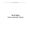
CCTVwindow
Client Software
Instruction Manual
VERSION 3.02SW
Contents
Page
1. General Information
1.2 Computer System Requirements
1.3 Conventions
4
4
4
2. Software Installation
2.1 Installing the Software
22. Uninstall Software
4
4
4
3. Basic Operations
3.1 Login
3.2 Graphic User Interface (GUI) Introduction
5
5
6
4. Device Management
4.1 Area Configuration
4.2 Add Device
4.3 Channel Configuration
4.4 Channel Configuration for DVR9K series
4.5 Group Configuration
4.6 Sort by Camera Configuration
9
10
11
13
14
16
18
5. Preview
5.1 Non-cycle Preview
5.2 Cycle Play (Sequencing)
5.3 Preview Control
5.4 Recording & Capture
5.5 Others
19
20
21
24
25
27
6. PTZ Control
6.1 RS485 Parameter Configuration
6.2 PTZ Control
6.3 Presets
6.4 Patrol
6.5 Video Parameters Configuration
30
30
30
31
31
33
7. Recording
7.1 Client Local Recording
7.2 NVR Storage Server Recording Configuration
34
34
34
8. Playback
8.1 Remote VOD
8.2 Local Playback
8.3 Event Playback
37
37
41
43
2
9. Remote Configuration
9.1 Remote Recording Configuration
9.2 Alarm
9.3 Network Configuration
9.4 Network Configuration
9.5 Account Management
9.6 Others
45
46
51
57
59
60
61
10. Alarm Linkage
10.1 Linkage Configuration
10.2 On Arm & Off Arm
63
63
64
11. E-Map
11.1 Add Map
11.2 Map Configuration
66
66
67
12. Utilities
12.1 Software Configuration
12.2 Log Management
12.3 User Management
70
70
71
74
3
1.
General Information
1.1
Overview
The CCTVwindow client is applicable to all Alien DVRs, the DVR9K, IP Traditional
Cameras, IP Dome Cameras and the Video Bridge.
1.2
Computer System Requirements
·
·
·
·
1.3
Operating System:
CPU:
RAM:
Display:
Microsoft Windows 2000 or versions above
Intel Pentium IV 2.4 GHz or models above
1Gb or above
1024×768 or above, minimum 16 bit colour
Conventions
The following conventions are used in this manual:
· DVR, IP Camera, IP Dome and Video Bridge are all referred to as a ‘device’
· Click refers to clicking the left hand mouse button
· Double click refers to double clicking the left hand mouse button
2.
Software Installation
2.1
Installing the Software
Double click the software and you will see the wizard shown.
Click “Next”to continue and input the user information and software installed location.
After that, an SADP installation wizard will pop up. Now click “Next”to start to install
WinPcap. If it is already installed, the installation can be cancelled.
Note: SADP (Scoped Address Discovery Protocol) is used as the on-line device finder.
This function is unavailable if the WinPcap is not installed. SADP discovers the IP
address of a device without knowing the address or subnet mask.
2.2
Uninstall Software
This software must be removed via Control Panel, Add/Remove Programs. Locate and
highlight ‘CCTVWindow’and click ‘Remove’.
Confirm the removal and allow the Installer to remove the application.
WinPCAP, if installed during the installation process must be removed manually –there
is a separate item for this in Add/Remove programs as well.
4
3.
Basic Operations
3.1
Login
This software has been set with a User of
admin and a password of 123456
When the software is initiated if the Automatic Login is ticked the username and
password will be automatically retained and there will be no necessity to enter the
username or password when logging in next time.
If the user wishes to change the password, then select a username and click Modify.
If the username or password is incorrect the following dialogue box will be displayed as
shown below.
If the user wants to cancel the login, then click Quit.
SPECIAL NOTE: Please stop all operations (e.g preview, recording, playback etc.)
before switching users.
5
3.2
Graphic User Interface (GUI) Introduction
There are 6 client software GUI areas as shown below.
1
2
3
4
5
6
1. System Area:
If you minimise the software by clicking on the –(minimise button), if you right click the
icon at the bottom of the taskbar
Preview, Setup, Remote VOD, Local
Playback, Event Playback, Map,
Log and Exit can be selected.
6
2. Menu Area:
3. Device Area:
4. Preview Area:
1
2
3
7
4
5. PTZ Control Area
PTZ
Control PTZ
Preset
Configure and call presets
Tours
Configure and call tours
Image
Brightness, Contrast,
Saturation, Hue and
Volume adjustment.
6. Alarm Info Area
Display alarm time, information and alarm sign. The area size can be enlarged by
dragging the top of the area upwards. You can fix the area size by clicking on icon
which turns to
but when it returns to
resume to its original size.
8
the area size will
4.
Device Management
Before any operation of this software a device needs to be configured in the menu. By
default a device called “DVR9K”is always set. As this software is used for DVRs, IP
cameras, IP Domes and Video Servers you may prefer to use a different device name.
You may use this device name, remove it and add another name that maybe more
applicable or create an additional device.
Click on Setup to enter configure mode and then click on Device Management.
2
1
3
9
4
4.1
Area Configuration
The software can be used to access various devices over a network and to allow for
places to be created as reference points for different devices. These reference points are
called areas. The default area is set as UK with a DVR9K. If you right click on the World
icon and select Delete Node the default settings will be deleted. If you now right click in
Area 1 you will see the following box displayed:
If you now left click on Add Area the following box will be displayed.
Enter the required Area name e.g UK, World, Town name etc. The first area created will
only allow the Area Name box to be completed, but if you for instance have set an area
name of UK and then set another area say Chesterfield by clicking on the UK icon, it will
display Chesterfield in the Area Name and UK in the Upper Area Name.
NOTE: The following are invalid in the Area Name :- Enter, Space, Tab, null, % and “
The maximum number of areas that can be entered is 50 areas.
When you select Delete Node, the sub areas, stream media servers and devices under the
root of the area will be deleted as well. Before attempting this you must stop preview or
record, otherwise a warning information box will be displayed.
10
4.2
Add Device
Right click the Area and the following box will be displayed:
Left click on the Add Device option and the following box will be displayed:
11
Normal IP mode
The default register mode is the Normal IP. After input the IP address, username,
password, port and channel No. Click the “OK”button to finish adding device.
Normal Domain mode
If you select normal domain, please fill in the blank domain name with the registered
domain name.
Private domain: If you configured the device with the address of IP Server that runs
normally, then the connected device can be resolved by IP Server; and the software can
get the dynamic IP address from IP Server by server name or serial number.
Private Domain mode
If you select private domain, please input the correct device serial number and IP address
of IP server in the DNS Address blank.
12
Note: When adopting a private domain, if you input device serial number, the software
will obtain the IP address from the IP server; If not, the IP address can be obtained by
using device name to resolve IP server, i.e. in that case, the device name here should be
the same with the one in the device. Click OK to finish adding device.
Right-click menu is available, double click the node can modify the device parameters.
Note: 50 devices can be added here.
4.3 Channel Configuration
Click on Get Channel Name to get the names of all channels.
13
Double click the channel name
and the Modify Channel
Information dialogue box will
be displayed. Note that Main
Stream is for device encoding
and Sub Stream is for network
transmission.
NOTE: The channel name will be replaced with the name saved in the device, if the
option Get Channel Name is selected.
4.4 Channel Configuration for DVR9K series
If this software is used with the DVR9K series then the IP channel management and
enable or disable analogue channel functions are available.
Right click the device name and
select “Remote Configuration”,
then the “Channel Configure”
menu will pop up. The “Analogue
Camera”will show by default.
Double click the selected
analogue channel to enable or
disable it.
Note: The DVR9K series cannot
preview and record this channel
after it is disabled, unless it is
enabled again.
14
Click “IP camera”to enter
the interface of IP channel
management.
Click “Add”to add IP
channel.
Input the IP address, user
name, password and port,
and then click “OK”.
Double click the selected channel to
modify the parameters.
Click “Delete”to delete the selected
channel.
After that, you can change the channel
number according to the added channels.
Double click the device name to modify
the device information.
Note: The DVR9K Hybrid supports adding of up to16 analogue channels and 8 IP
channels but please refer to the User Instruction Manual for more details.
15
After that, the added IP channel will be seen in the
channel list of the device.
If IP channel cannot be connected, the icon will be shown
as
4.5
Group Configuration
Click the Sort by group button to enter group area management window.
4.5.1 Sort by group
There is the default group. You can add
channels in it or delete it.
Right click in the empty area and you
will see sub menu as shown on the right.
Select “Add Group”.
Input the group name and click “OK”.
16
Double click the group name to change the
group name.
Right click the group name and select
“Delete Group”to delete the selected group.
Note: Enter, Space, TAB is invalid in the group name, which cannot be null, and should
not contain the following characters, including % and ’.
4.5.2 Channel
After adding the group, the channels in the list area can be moved to selected group.
Channel Add
Select the channel from the list area, and click
key and move it to the
selected group. The type of channel name in the group area is as “device name channel
name of the list area”.
Select the device in the list area and click
device can be moved to the selected group.
key and all the channels of the
17
Using
and
keys to adjust the channel sequence in the group list.
Channel delete
Use
key to delete the channel or group in the group area.
Note: One channel can be added to one group only once. Different groups can contain the
same channel. Max 50 channels can be added to one group.
4.6
Sort by Camera Configuration
Click Sort by camera button to enter short key management window. Only the channels
can be added to the sort by camera area. Select the channel from the list area, and click
key and move it to the sort by camera area. The type of channel name in the
group area is as “device name channel name of the list area”. Select the device from the
list area, and click
key to add all the channels of the device to the sort by
camera area.
Use
key to delete the channel in the sort by camera area.
18
5.
Preview
After configuring the device, double click the
key to return to the preview
interface. Click the “List”and “Group”keys to switch between two modes.
Click
key and then
key and
enter “Advanced Configuration”and enable
button to
option to save
current preview state including window division and preview channel for next login.
Play windows are divided into 2×2 mode, max support 64 window divisions.
Stop
Cycling
Window
Division
Play
Record
Capture
Multi-screen
19
Previous/Next Page
Resume Cycling
Note: The window division and channel sequence can be remembered by the Client
Software on exit and will play automatically after login next time.
5.1
Non-cycle Preview
5.1.1 Play by Node
Double click the device name or drag it to the play window to preview (not enable cycle
preview)
Double click the channel name to preview
the corresponding cameras.
Double click the device name to preview the
corresponding cameras of the device in the
current window divisions.
Double click the group name to preview the
corresponding cameras of the group in the
current window divisions.
You can also preview them by dragging
them to the play windows. The play window
shows as the figure on the right.
5.1.2 Sort by camera Preview
Sort by camera mode
In the device list mode if the sort by camera has been configured, press
button of
the preview interface to view all the corresponding channels in the sort by camera area in
the current window divisions. If the channel number is larger than the window division
number, user can click
and
to change the page to preview. Find more
details at 4.6 Sort by Camera Configuration.
20
Sort by group mode
Click the “Sort by group”to go to this mode, if the sort by group has been configured,
then press
button in the preview interface to view all the corresponding channels
in the sort by camera area in the current window divisions. If the channel number is
larger than the window division number, user can click
and
to change
the page to preview. Find more details at 4.5 Sort by group Configuration.
5.1.3 Stop Playing
There are 3 ways to stop live preview.
Double click the channel to stop playing.
The play icon is
so double click it to
stop previewing this channel and the icon
will then become
Right click video to stop playing
Right click in the play window and the play
menu will display. Click “Stop Play”and the
live view will stop. Meanwhile the play icon
will become
Stop all playing
Click the key in the preview panel to stop all the live view channels.
5.2
Cycle Play (Sequencing)
5.2.1 Cycle Configuration
Click
key to enter the configuration interface. Then enter the local
configuration by clicking “Software Configuration”key.
21
Enable Cycle:
Tick Cycle Play and input the cycle time, then press “Save”and return to preview
interface.
Note: Cycle time should be between 20 and 300 seconds.
Disable Cycle:
Click to disable Cycle Play and save.
5.2.2 Cycle Play of Device/Group
Start cycle
Double click the device name and all the channels
of the device begin to cycle in the selected window
division from the 1st channel.
Double click the group name and all the channels
of the group begin to cycle in the selected window
division from the 1st channel.
Drag the node of the device to the window, and then
all the channels of this device begin to cycle. Drag
the node of the group to the window, and then all the
channels of this group begin to cycle.
Pause/Resume Cycle
If the current window is in the device/group cycle
mode, right click the cycling window, click “Pause
cycle device”or “Stop cycle group”to pause cycling
to retain the current image.
Click “Pause cycle”key
to pause all the cycling window divisions.
22
If the current window is in the device/group cycle
mode, right click the paused window, click “Resume
cycle device”to restart cycling.
Click “Resume cycle devices”key
to restart all the paused channels.
5.2.3 Mixed Cycle
Mixed cycle mode enables the software to sequence preview channels by group or sort by
camera. The default window division is 2×2.
Sequence Sort by camera Channels
Click “List”key to display channel list.
Click
key to start mixed cycle play. Take 2×2 window division for example, if
there are 8 channels in the sort key area, then start cycle playing, the first 4 channels will
be displayed in the window, then after one cycle period, the last 4 channels will be
displayed in the window.
Click
button in the preview panel to stop sequencing.
Click
channels.
key to display the first 4 channels, click
key to display the last 4
Note: Click button
or
to pause the channel sequence cycle of sort by
camera. This function needs sort by camera configuration first.
Sequence Group Channels
Click “Sort by group”key to display group channel list. (Please stop playing before
switching to group channels.)
Click
key to start mixed cycle play. Take a 2×2 window division for example. If
there are 2 groups in sort by group area and each of them has 4 channels, then start cycle
playing and 4 channels of the first group will be displayed in the window.
After one cycle period, 4 channels of the second group will be displayed in the window.
23
Click
channels.
key to display the first 4 channels or click
key to display the last 4
Note: Click button
or
to pause the channel sequence cycle of sort by group.
This function needs sort by group configuration first.
5.3
Preview Control
Full Screen:
When previewing, click
key to preview in full screen or to exit click
key.
Enlarge:
When in the multi-screen preview mode, double click the selected image to enlarge it or
double click again to resume.
Main/Sub Stream:
Main stream is for recording and sub stream is for network transmission when bandwidth
is low. The stream will take effect after re-previewing the device or channels.
The software uses the main stream by default but if needed the user can switch to sub
stream to preview.
Right click device name and
select “All Main Streams”or
“All Sub Streams”to change
the device stream type.
Right click channel name and
select “All Main Streams”or
“All Sub Streams”to change
the channel stream type.
Note: The sub stream preview needs the device to support or else the sub stream preview
will fail.
24
Voice Control
Right click the selected window, select
“Audio on”to enable audio preview, right
click again and select “Close Voice”to
disable audio preview.
Note: The software only can open voice of one window at the same time. If the voice of
the next window is opened then the voice of the previous will be closed automatically.
5.4
Recording & Capture
Recording and capture is only available in the live view mode.
Note: If the channel is in the recording mode, click “Stop”button to stop recording, and
the preview, cycle play are stopped as well.
5.4.1 Recording
Record disk configuration
Configuration Path: :
Select the saving hard disk of recorded files in Store setup. Note that the files will be
found into a “RecordFile”directory. This directory will be created by this client if
necessary assuming the Windows user account has the necessary rights, otherwise local
recording will fail.
Immediate record
When previewing, click
key to start recording and the icon turns red.
The channel icon turns darker. Click the record button to stop recording.
25
After recording, the hint window with index
of recorded files will be displayed. Click the
hint to open the target folder.
5.4.2 Capture
Configuration Path:
Image format configuration
Path configuration
Default saving path: C:\Picture, click
Capture
When previewing, click
key to change the saving path.
key to start capture.
After capture, the hint window with capture index
will display. Click the hint to open the target folder.
26
5.5
Others
5.5.1 Voice Talk & Broadcast
In preview interface, right click the device name and
the sub menu will be displayed.
Click “Start Voice Talking”to talk to the selected device.
If the device is a DVR9K, then there will be two voice
talk channels.
Note: Client software only supports one voice talk at
the same time.
5.5.2 Audio broadcast
Right click area name and select “Audio Broadcast”
to talk to the area.
5.5.3 Alarm Output Control
Right click the device name and the sub menu will
display. Select “Alarm Output Control”to turn on
or off the alarm output, and define alarm output name.
27
Click
and it changes red in colour,
turns on the alarm output and activates the name
modified function. A re-click of the key will turn
off the alarm output.
5.5.4 Device Status
Right click the device name and the sub menu will display. Click “Device Status”to get
device working information, including channel and hard disk status.
Note: Some options will turn grey and become unavailable if the device doesn’t support
them.
5.5.5 Remote Control Panel
Right click the device name and the submenu
will display. Select “Remote Control Panel”
and the control panel will display as shown.
You can click the buttons on the panel and
control device similar to using the front panel
DVR.
28
5.5.6 Two Screen Preview
If the computer is connected to two monitors
and opened, there will be a Two Screen button
displayed.
Click this button to reveal a drop-down menu
that includes AUX screen preview, Electronic
map and Remote VOD.
Click AUX screen preview and the second monitor will display the preview window.
The aux screen operation is the same as the main screen so refer to the earlier chapters.
Note: If the main screen displays 64 divisions, the aux screen will not open. After
opening the aux screen, they both support a maximum of 32 window divisions.
29
6.
PTZ Control
6.1
RS485 Parameter Configuration
Before PTZ operations, please make sure that RS485 parameters have been correctly
configured in software.
Click Setup and enter the corresponding
interface. Right click the device name and
select Remote Configuration from the
submenu. Click on + to reveal drop
down options, shown in figure on the right.
Set correct parameters for the each channel.
Note: RS485 configuration must be the same as the PTZ configuration.
6.2
PTZ Control
Return to preview interface and user can
control PTZ. There are 8 keys to control
PTZ directions, and the active bar to
change PTZ speed, which is adjustable
from 1 to 7 and default speed is 4.
Click
key to start auto scan.
Click the function keys on the right to
adjust focus, iris and zoom.
Other PTZ Control Mode –Screen PTZ Control: user can control PTZ by dragging and
click in the play window.
30
6.3
Presets
Select one channel and click the Preset
key on the PTZ control panel and enter
preset edit window.
Select one play window, and right click the
preset list or click to add, modify and delete
preset.
Select one play window, and right click the
preset list or click
to add, modify and
delete preset.
Move the PTZ to the position you want, and click
Add to input preset name, then click OK to finish.
Then double click preset in list or click
to call it. Right click preset to modify or delete this
preset. Click
to delete preset as well.
6.4
Patrol
After adding two or more presets for one channel,
you can set a patrol with presets for PTZ.
1st step: select one channel and click Tours
key to show patrol list.
31
32
2nd step: Click
or right click patrol
name then select the preset you would like to
enter patrol configure menu.
3rd step: Click Add patrol points or you can
also click preset area to select presets from the list.
4th step: Set the time and speed for the preset.
Note: Dwell time is between 1 and 128 seconds.
Dwell speed is between 1 and 40.
5th step: Repeat the 2nd and 3rd step to add the
presets to the patrol. Then click Save key to save
the settings.
After configuration, you can choose the patrol from the list, and call/stop them by
clicking
and
keys.
33
6.5
Video Parameters Configuration
Click the Image key to show the video parameters
configuration menu. Move to adjust the video
parameters. (Range: 1-10, default value: 6).
Brightness
Contrast
Saturation
Hue
Volume
6.6
Keyboard and Joystick Control
Reserved for future use.
34
7.
Recording
7.1
Client Local Recording
7.1.1 Store Setup
Click tab page
to enter record setting interface
It can set the record file store partition and the max record file size in the store setup.
NOTE: Files will be sent to the directory RecordFile on the respective hard drive.
See 5.4
7.2
NVR Storage Server Recording Configuration
User can remotely configure the recording schedule and playback the recorded files of
the NVR storage server through client software. Click NVR Recording Setup
to enter the NVR configuration.
7.2.1 Add NVR Server
Click NVR Configuration to enter
NVR configuration interface.
Input the NVR server name, IP address
and port, and click ADD key to finish.
Note: Max 16 NVR servers can be added to this software. The default server port and
VOD port are 8320 and 8554.
7.2.2 NVR Recording Mode Configuration
After finish adding NVR server, user can set the recording mode for custom setting, using
the schedule recording setting.
35
1st step: Select added NVR servers from
list, click
to enter modify recording schedule.
2nd step: Select the record template, set the
recording period for the mode. Click the mouse
to add recording schedule; right click to cancel
recording schedule.
Recording type includes Schedule Recording
& Motion Detection Recording. Then use left
click to add section, right click to delete section
in the date area.
3rd step: click OK to finish modifying the template.
Note: The unit of recording mode is in half an hour blocks. Green means schedule
recording, pink means motion detection recording and white means no recording.
7.2.3 NVR Recording Schedule Configuration
NVR server realises the record unified-storage and can be set through this software.
1st step: Select the NVR server
from the NVR pull-down menu.
36
2nd step: Select the device or channel
for recording. If device selected, it will
be effective to all the channels of the
device.
3rd step: Configure the recording
schedule. Select the mode from
Recording plan mode and select the
disk group to save the recorded files.
If necessary, enable stream media server and input the IP address and port.
Click Save to finish the NVR server schedule recording configuration.
37
8.
Playback
There are 3 options for playback, one is Remote VOD, the second is Local Playback
and the third is Event Playback which can be chosen by clicking the
key.
Remote VOD: Searching the recorded files from hard disk of DVR or storage server.
Local Playback: Searching the recorded files from hard disk of PC.
Event Playback: Searching motion detection or alarm recorded files.
8.1
Remote VOD
Click Playback and select Remote VOD
interface.
to enter the playback
1
2
3
4
5
6
Area
Description
System Area
1
Playback Windows
2
Play Control Buttons
3
Area
4
5
6
38
Description
Device Area
Query Area
Time Axis Area
8.1.1 Remote VOD Query
1st step: Select the playback channel and window.
2nd step: Select recorded file type and query time.
3rd step: Add information of card number. For ATM DVR enable Query by Card No.
and input the overlaid card number to search. Optional facility.
4th step: Click
key to search the matched recorded files, if there are,
they will show in the time axis area.
5th step: Click
key to start playback. You can choose time by dragging mouse to
the time you want on the time axis.
Select one channel then drag into playback window. If there is recorded file on this day, it
will playback from the very beginning of this day.
If you enable synchronous playback, then the 4 windows will playback synchronously. If
the start time of the 4 windows is not same, the most advanced window will wait for the
other windows until they reach the same time.
39
8.1.2 Playback Control
When playback has succeeded, the play window will show as below:
Descriptions on playback buttons:
Note:
In the single frame playback mode, every time you click the
files will play forward by one frame.
button, the recorded
Only one window audio can be opened at the same time when in VOD mode. If the audio
of next window opens then the audio of previous window will be closed.
Record file Clip
During playback, click
once to set begin
time of video clip, click it again to set end time of
video clip. After saving the video clip, a message
will be raised, click it to open video segment.
40
Record file download
After searching the recorded file, you can click
to download file to local PC.
You may click on message to open the downloaded saved directory.
You may go to Configure
saving directory.
Local Settings
Path configuration to change the
Playback capture
User can also get the remote capture by clicking
button, and you will see the pop up message. Click
the picture to open the capture and click the path
to open the capture folder.
Digital Zoom
Click
to trigger the digital zoom function.
In the digital zoom mode, the playback window will display the video as PIP, with the
main window displaying the zoomed in part.
Move the area on the right, click
or
to change the zoom ratio. Drag the red frame and
the zoom area will move with it. Roll the mouse and
user can change the zoom ratio. Click the
button again to close the digital zoom.
41
8.2
Local Playback
Click
playback interface.
and choose Local Playback
to enter the
1
2
3
4
5
6
Area
1
2
3
Description
System Area
Playback Windows
Play Control Buttons
Area
4
5
6
8.2.1 Local Playback Query
1st step: Select the playback channel and window.
2nd step: Select recorded files type and query time.
42
Description
Device Area
Query Device
Time Line Area
3rd step: Click
key to search the matched recorded files, if there are,
then they will be shown in the time axis area.
4th step: Click
key to start playback. You can choose time by dragging mouse to
the time you want on the time axis.
Select one channel then drag into playback window. If there is recorded file in this day,
software will play it back from the very beginning of the day.
Note: If selected
then 4 windows will playback
synchronously. If they are on different time scales currently, the others will move to the
same time scale in the selected window.
8.2.2 Playback Control
The following playback controls are detailed below:
Return to beginning
Play
Play speed adjust bar
Single frame
Single screen
Full screen
Volume
Pause
Stop
4 screen setup
Capture
Digital zoom
Stop all
Note: In the single frame playback mode, every time you click
button, the
recorded files will play forward by one frame.
Only one window audio can be opened at the same time when in VOD mode. If the audio
of next window opens then the audio of previous window will be closed.
43
8.3
Event Playback
Click the
button, select
in the event playback
interface.
By event playback function, user can search record of motion detection or sensor alarm.
If the matched record exists it will be displayed in the interface. User can select and play
back from it.
Note: Event playback function is supported by DVR9K series DVR, with firmware
version 1.1 or higher.
8.3.1 Record search
1st step: Select a device.
2nd step: Select the event type, camera channel/alarm channel and the event date.
3rd step: Click
to search record file, if there are record files that match
the options, they will be displayed on the time line.
4th step: Select the channels to be played back. Move the mouse and select a time point,
then click
and selected channels will play back.
Note: Maximum 4 channels event playback.
44
8.3.2 Playback control
Event playback interface as shown below:
The software only can only open one stream of audio at the same time. If the audio on the
next window is opened then the audio on the original channel will be closed
automatically.
45
9.
Remote Configuration
You can remotely configure the parameters of this device, including recording schedule,
alarm schedule etc.
Click:
Right click the device and select
Remote Configuration.
If the device is DVR9K series, after clicking the Remote Configuration you need to
click
interface.
key in the display menu and enter the configuration
46
9.1
Remote Recording Configuration
9.1.1 Encoding Parameters Configuration
Select
to enter encoding parameters configuration interface.
Note: If the device is DVR9K series, click Switch to
IP Channel and select IP channel to configure the
parameters of IP camera.
Parameters
Encoding Parameters
Stream Type
Resolution
Video Quality
Bit rate Type
Max Bit rate
Frame Rate
Frame Type
I frame Interval
Description
Main/Sub stream and Event Parameters
Video & Audio or Video stream
Recording Resolution
Highest, Higher, High, Average, Lower, Lowest
Variable and Constant
Maximum bit rate of the compressed stream
Record frame rate from 1/16 to full frame rate (25fps)
BBP, BP and Single P frame
The interval between two I frames
9.1.2 Schedule Recording
Select
to enter configuration interface.
Tick the Enable Recording box.
47
Click Settings in the Record Time box to
enter recording schedule configuration
interface.
Click on Weekday box and select day of
the week or the whole week for recording
time.
Click
for the
recording type. The All Day Recording or
up to 8 periods can be selected as well.
Note: The time of each period must run
consecutively and must not overlap.
Click the Settings box next to the
Advanced Settings in the Schedule Record
menu. User can set pre/post record time.
Note: Recording Expired, Redundant and
Audio Record are only available for the
DVR9K series DVR.
9.1.3 Motion Detection Recording
Click
to enter
motion detection recording interface.
Note: If DVR9K series, click Switch to IP
Channel and select IP channel to configure
the parameters IP camera.
1st step: Select channel number for motion
detection.
2nd step: Enable motion detection to activate
Setting Area, Arm Schedule and Linkage
settings.
48
3rd step: Set the motion detection area and
sensitivity. Sensitivity 1 is lowest and 6 is
highest sensitivity level.
Enable Start Draw and select the detection
area by using the mouse.
4th step: Set the detection time.
Arm Schedule can be for one day or for the whole
week and up to 8 periods for one 24 hour day.
5th step: Set the Trigger Recording for linkage.
Click Setting in the linkage area and select Trigger
Recording tab.
6th step: Select
and tick Enable
Recording.
49
7th step: Set the detection recording time.
Click Record Time Settings box.
Select Weekday day of the week or the whole
week for recording time.
Click
type and change it to
for the recording
The All Day Recording or 8 periods can be selected
as well.
Note: The time of each period must be consecutive
And must not overlap. The valid time is the
intersection of the motion detection time and motion
detection recording time.
9.1.4 Alarm Recording
Select
1st step: Select alarm input.
Note: If the device is DVR9K series, you can click
Switch to IP channel to configure the IP channel
alarm input.
2nd step: Select the type of alarm input, NO or NC.
Note: The settings will become effective after
rebooting.
50
3rd step: Enable Alarm Handle to activate Arm
Schedule & Linkage Method.
4th step: Set the arm schedule for alarm input.
Click Settings in Arm Schedule menu.
Select a day of the week in Weekday or
the whole week for recording time.
The All Day Record or 8 periods within a 24
hour day can be selected as well.
Note: The time of each period must be consecutive
and must not overlap.
5th step: Set recording channel triggered by alarm.
Click Settings in Linkage menu and then select
Trigger Recording tab.
Enable the recording channels you want.
6th step: Enter schedule recording interface.
Click
to enable Recording.
51
7th step: Set the recording time for alarm input.
Click Settings in Record Time.
Select a day of the week in Weekday or the whole
week for recording time. Set the record type to
Alarm Recording. The All Day Recording or 8
periods can be selected as well.
Note: The time of each period must be consecutive
And must not overlap.
9.1.5 Other Recording Modes
Other Recording Modes include Motion detection & Alarm, Motion detection | Alarm.
& means recording is triggered when two situations happened together, and | means
recording is triggered when one of the situations happen.
The configurations are the same with Motion detection recording or Alarm recording.
9.2
Alarm
You can configure motion detection alarm, signal level alarm, video loss alarm and other
alarm and linkage through client software.
9.2.1 Motion Detection Alarm
1st step: Select channel number for motion
detection.
2nd step: Enable motion detection to activate
Setting Area, Arm Schedule and Linkage settings.
3rd step: Set the motion detection area and sensitivity.
The sensitivity 1 is lowest and 6 is the highest level.
Enable Start Draw and select the detection area by
using mouse.
52
4th step: Set the detection time.
Arm Schedule can be one day or the whole week
and up to 8 periods in one day.
5th step: Set the alarm linkage for motion detection
and select alarm output channel.
Alarm Linkage Description:
Linkage
Warning on Monitor
Audio Warning
Upload to Center
E-mail Linkage
Trigger Alarm Output
Description
When the alarm signal is detected, the image of corresponding
channel will pop out as single screen.
Alarm triggers buzzer
Upload the alarm signal to the center, such as client software
When the alarm signal is detected, the client software will send the
email to the designated mailbox.
Trigger alarm output of the device; if the device is DVR9K series,
triggering alarm output of IP channel can be selected as well.
9.2.2 Signal Level Alarm
Select
1st step: Select alarm input.
Note: If the device is DVR9K series DVR click
Switch to IP channel to configure the IP channel
alarm input.
53
2nd step: Select the type of alarm input,
NO or NC
(NO = normally open NC = normally closed).
Note: The settings become effective after rebooting.
3rd step: Enable Alarm Handle to activate
Arm Schedule & Linkage Method.
4th step: Set the arm schedule time for alarm input.
Click Settings in Arm Schedule menu.
Select day of the week or the whole week for
recording time. The All Day Record or 8 periods can
be selected as well.
Note: The time of each period must be consecutive
and must not overlap.
5th step: Set the alarm linkage for signal level and
select alarm output channel.
54
6th step: Set Trigger Recording for signal
level alarm.
7th step: Set PTZ linkage for signal level alarm.
Note: Alarm input can link several PTZ channels,
but one channel can only link one option of preset,
sequence and pattern.
9.2.3 Video Loss
If the video input signal is lost, user can set
relevant linkage operation.
1st step: Select the channel number for video loss.
Select
Note: If the device is DVR9K series click on
Switch to digital channel to configure the video
loss on IP channel.
2nd step: Enable Video Loss to activate settings
in Arm Schedule and Linkage.
55
3rd step: Set the arm schedule for video loss.
Click Settings in Arm Schedule menu.
Select day of the week or the whole week for
the arm schedule. The All Day Record or 8
periods can be selected as well.
Note: The time of each period must be
consecutive and must not overlap.
4th step: Set linkage for video loss.
Click Settings in the Linkage menu.
9.2.4 Video Tampering
1st step: Select the channel number for video
tampering.
Select
Note: If the device is DVR9K series you can click
Switch to digital channel to configure the video
tampering of IP channel.
2nd step: Enable Video Tampering Alarm to
activate settings of Setting Areas, Arm schedule
and Linkage.
56
3rd step: Set the video tampering area and
sensitivity.
The sensitivity can be divided into three
levels: Low, Medium, and High.
Enable Start Draw and select the detection
area by using mouse.
4th step: Set the arm schedule for video tampering.
Click Settings in Arm schedule menu.
Select day of the week or the whole week for the
arm schedule. The All Day Record or 8 periods can
also be selected.
Note: The time of each period must be consecutive
and must not overlap.
5th step: Set linkage for video tampering.
Click Settings in the Linkage menu.
9.2.5 Exceptions
Exception parameters are used for alarming an abnormal event. These include HDD Full,
HDD Fault (HDD errors or HDD not initialising), Network Broken, IP Address Conflict,
Illegal Access (user name or password wrong), Video Output Standard Mismatch and
Video Signal Exception (video signal unstable).
57
Select the exception type and handle method.
Select
to enter configuration interface.
9.3
Network Configuration
9.3.1 Basic Configuration
Select
Configure the network according to the actual
situation. If there is a DHCP server in the network,
enable Obtain Auto and reboot the device to get
the IP address automatically.
Select Advance to enter advanced configuration.
You can configure preferred DNS server1 and spare
DNS server2, IP address of alarm host and IP server.
Parameters
DNS1 DNS2
Alarm Host
IP Server
Description
Preferred and spare DNS server
Alarm signal can be uploaded to the IP address automatically
IP address of IP server
9.3.2 PPPoE
This protocol is primarily used in the USA and is not available in the UK which uses
PPPoA. This option is therefore not supported.
58
9.3.3 DDNS
This option applies to equipment used in the USA that does not use ADSL. This option is
therefore not supported.
9.3.4 NTP
Adopting the NTP function can enable this software to synchronise the time and date of
the device on a regular time interval.
Select
Tick to enable NTP function.
Note: The time synchronisation interval is
0~10080 minutes with a default of 60mins.
If the device is connected to the public network,
the IP address of NTP server provided by supplier
of service can be input in the blank Server
Address box.
9.3.5 NFS
The NFS option allows recorded data to be saved to a network storage device provided
by a NAS server. This equipment is not available so this function is not supported.
9.3.6 E-Mail
Through E-mail configuration, Email can be sent to the designated mailbox when there is
an alarm. Note that the Email function is currently only available on the Alien Pro
models Alien504, Alien508 and Alien516.
Select
If server authentication is needed, tick authentication
box and input user name and password. Input the
sender and recipient information and if there is a need
to send a picture then tick Attachment box.
Note: Make sure that the device supports email function
and that server allocates the storage space correctly.
59
9.4
Channel Configuration
9.4.1 Channel Display Settings
Select
You can configure channel name, OSD and related
parameters here.
9.4.2 Video Mask
1st step: Select channel number and tick
Enable Video Mask.
Select
Note: If the device is DVR9K series, click
Switch to digital to choose IP channel and
configure the parameters.
2nd step: Set the mask area.
Click Settings to enter area set menu.
Tick Start Draw and select the mask area by
clicking and dragging the mouse.
9.4.3 Text Overlay
You can add characters on the screen for a channel.
Select
Tick Strings 1 to enable text overlay then double
Click the strings area to input the characters you
want to overlay on the screen.
Note: If the device is a DVR9K, then only analogue
channels support text overlay.
60
9.5
Account Management
9.5.1 General User and Password control methods
There are three methods of controlling users and passwords.
a. Directly via the device
b. Via the Client using Remote Configuration
c. Via the Client using User Management
a. Directly via the device
The first method is by setting users and passwords direct in the device and not by the
software. This is explained in the device hardware manual.
b. Via the Client using Remote Configuration
The second method which is described in this section of this manual, is to enter the
remote configuration menu in this client software and this make changes to the accounts
stored in the device itself.
c. Via the Client using User Management
The third method is described in section 12.3 under User Management. This allows user
and password control within the client software only, and takes priority over the device
setup. Note that these changes apply to this installation of the client software and do not
change the settings in the actual device. This method must be used with care.
9.5.2 Via the Client using Remote Configuration
The default user name and password of device administrator are “admin”and “12345”.
Administrator can remotely add, delete users or distribute authority for users. The new
added users are divided into two levels: user and operator. (For “Remote Configuration”
privilege, operator has “Voice Talk”rights, but user does not; for “Channel
Configuration”privilege, operator has all the rights, but user has local playback and
remote playback rights.)
Select
61
Click Add to add user.
Note: If you set the IP address or physical
address, then only the PC with the same IP
address or physical address can access the
device over the network.
Click Modify to change the user name and
password; click Delete to delete the user.
Allow ticked means privilege granted, unticked
means privilege not granted. If the privileges
are related to channels, then a ticked status
means granting the privileges for all channels;
unticked status means granting no privileges
for all channels.
Click
to expand the channels, and set the
privilege for each channel. If only some channels have operating privileges, the status
will be
Note: Please refer to the user manual of the device for the detailed descriptions on
privileges.
9.6
Others
Remote Upgrade:
Click
Click “Browse”to search the local upgrade file,
click “Upgrade”to start upgrade remotely.
Note: Using an incorrect BIOS version can damage the DVR. Do not attempt any
upgrade unless this is confirmed by your installer or supplier.
62
HDD Format:
Click
Note: Please backup the data before formatting
the hard drive.
63
10. Alarm Linkage
According to the various alarm signals uploaded from the device, this software can
configure the different linkages for them.
10.1 Linkage Configuration
Path:
1st step: Select the device from the device area on the left, activate the alarm type and
alarm linkage type options.
2nd step: Select the alarm type, after selected,
the alarm type status will become
3rd step: Select the alarm linkage type
for the alarm type, and status
means selected.
64
Description of Alarm Linkage Types
Linkage Types
Descriptions
Display image when alarm occurs
E-map Alarm
Sound Alarm
Alarm Link Recording
Display single screen image when alarm occurs
When alarm occurs, related hotspot on E-map flashes
Alarm triggers local alarm sound
Alarm triggers local recording of alarm channel
Note: Before setting alarm linkage configuration, the alarm schedule and handle method
of the device are required to be set correctly.
10.2
On Arm & Off Arm
You can choose “Arm software”and “Cancel Guard”to decide whether to handle alarm
signal or not.
Right click the device name in the preview mode
and select Arm software to enable the monitoring
of device alarm and the device icon will be shown
as
If the device is on guard, right click the device
name. You can select Cancel Guard to cancel
alarm monitoring.
65
Right click the area name, select Arm All
or Disarm All for all the devices.
After the device or the area fortified, the alarm linkage will become effective when there
is an alarm detected.
66
11. E-Map
Click
key to show the E-map window.
Toolbar Buttons Descriptions:
11.1 Add Map
1st step: Click
button to enter map edit mode, the cursor will change to
2nd step: Right click the black area and select
Add Map (or click
button to display
Map Info Area and
right click the area
and select Add Map), then the add map window
will display.
3rd step: Add the map.
Click Browse to search the image file on the
local PC. Click OK after renaming the file to
finish.
Note: Supported file formats are BMP & JPEG.
67
4th step: Add sub map, right click the image
name in the map info area or the image itself,
and the sub menu will display.
Select Add Sub E-map to add sub map.
Select Properties to change the map name and
image file.
Select Delete to delete the selected map.
11.2 Map Configuration
Map configurations need to be done under the map edit mode.
11.2.1 Hot Spot
Through hot spot configuration, user can mark out the location and live view of the
monitoring points on the E-map.
Add Hot Spot
1st step: Enter add hot spot interface.
Right click the image name in the map info area
or the image itself, and select Add Hot Spot.
2nd step: Input the name of hot spot, click
and select the icon for hot spot.
You can also click
characters.
to change the colour of
3rd step: Select the channel you want to relate to in the
Related Camera list and press “OK”to finish.
After adding hot spot, move the mouse to the hot spot icon
Which will change to
and you can move the hot
spot by pressing left
button and dragging.
68
Input the key words in the Find box. Click
to find the channel whose
name embraces the key words.
If the alarm links to E-map is set as alarm handling method, in the non-edit mode the hot
spot will flash when there is an alarm on a triggered channel. Double click the hot spot
and the live image of the related channel will display.
Edit Hot Spot
In the edit mode, right click the hot spot and the edit menu
will display.
Select Delete to delete the hot spot; select Properties to change the name, appearance
and related monitoring point of the hot spot.
11.2.2 Hot Region
Hot region configuration can be used for displaying the sub map in the main map.
Add Hot Region
1st step: Enter hot region adding interface. Right
click the image name in the map info area or the
image itself, and select Add Hot Regions.
2nd step: Input the name of the hot region, click
button to select icon for hot region.
You can also click
the characters.
to change the colour of
69
3rd step: Select the map from the Related E-map
list, and press OK to finish.
After adding hot region, move the mouse to the hot
region icon and it will change to
and you
can move the hot region by
pressing left button and dragging.
After hot region is correlated to the map, double click the hot region icon in the non-edit
mode will show the related map.
Note: You cannot edit map unless in the edit mode.
Edit Hot Region
In the edit mode right click the hot region icon and the
edit menu will display.
Select Delete to delete the hot region; select Properties
to change the name, appearance and related map of the hot region.
Right click the map in the edit mode, select
Delete All Link to delete the all hot spot and
region of the map.
70
12. Utilities
12.1 Software Configuration
Click
Descriptions on Software Configuration
71
Click Advanced Configuration to enter
alarm configuration, log maintenance and
other configurations.
Descriptions on Advanced Configuration:
After enabling inspection, if the device is off-line, then the alarm light will flash and the
detailed information will be listed; if the device is on-line, the alarm light stops flashing
and on-line information will be listed as well.
12.2 Log Management
Click
to enter the management interface.
72
12.2.1 Log Query
1st step: Select the area, device or channel you want to search from.
2nd step: Select type and subtype for the log you want to search for.
System Log: Record information on login, logout and software configuration.
Operation Log: Record information on the software operation.
Alarm Log: Record information on the alarm which must be linked as alarm link type.
Remote Log: Record information on operations of the remote device.
3rd step: Select the start time and end time for the log query, click
button and the log match condition will show in the list.
73
Double click the date in the list and the logs of that day will show in the information list.
Enable Query by user (i.e.
) you can search log by users.
Note: Up to 2000 logs can be displayed at a time.
12.2.2 Playback Linked Recordings
If the logs contain linked recordings, then you can play them back.
Click icon
in the list to play back the linked recordings.
74
12.2.3 Export Log
Click
button to export current logs as Excel or Txt format.
12.3 User Management
There are three methods of controlling users and passwords.
a. Directly via the device
b. Via the Client using Remote Configuration
c. Via the Client using User Management
a. Directly via the device
The first method is by setting users and passwords direct in the device and not by the
software. This is explained in the device hardware manual.
b. Via the Client using Remote Configuration
The second method is to enter the remote configuration menu in this client software and
this make changes to the accounts stored in the device itself.
c. Via the Client using User Management
The third method is described in this section under User Management. This allows user
and password control within the client software only, and takes priority over the device
setup. Note that these changes only apply to this installation of the client software and do
not change the settings in the actual device. Therefore changes are not reflected in
another PC loaded with this client software. This method must be used with care.
Click
12.3.1 Add & Delete User
Right click the user list on the left, and
select Add User.
Input the user name, password and select
the user level, then click “OK”to finish.
There are two options for user level:
Administrator and Guest. Administrator
has all the rights by default, but Guest,
you need to set the rights for it.
Double click the user name or right click
it and select Modify User to change the
password and user level.
Note: The administrator registered when
the software ran for the first time can
change password and user level;
administrator can change user password
but guest has no rights on user management.
76
User Privileges Descriptions:
Note: The administrator can be modified in the login dialog box instead of the user
management. The password cannot be null and should be more than 6 characters.
12.3.2 User Rights Distribution
Select a guest, and click the rights tree on the right to distribute the rights for user.
Note: The operations are available for the guest only when the corresponding rights are
allocated.
77