1
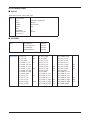
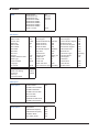
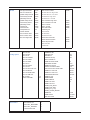
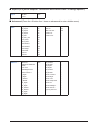
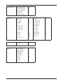
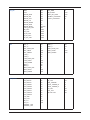
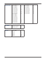
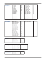
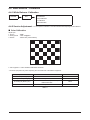
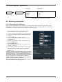
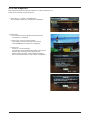
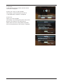
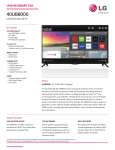
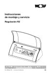
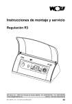
4-3. Factory Mode Adjustments 4-3-1 Entering Factory Mode To enter ‘Service Mode’ Press the remote -control keys in this sequence : - If you do not have Factory remote - control Power OFF MUTE 1 8 2 Power On 4-3-2 How to Access Service Mode Using the Customer Remote 1. Turn the power off and set to stand-by mode 2. Press the remote buttons in this order; POWER OFF-MUTE-1-8-2-POWER ON to turn the set on. 3. The set turns on and enters service mode. This may take approximately 20 seconds. 4. Press the Power button to exit and store data in memory. - If you fail to enter service mode, repeat steps 1 and 2 above. 5. Initial SERVICE MODE DISPLAY State Mode: CDTV . RES : 480I Option ADC/WB Control Expert Advanced T-CHE7AUSC-0062 T-CHE7AUSS-1006 SDAL-LB650-4.2.27-016 RFS:25_2G_64_512-26 T-CHE7AUSC 2009-03-09 FRCQ FW : 1008, CONFIG : 4900 ZIG BEE VER : 502 Type : 46A2UF0E Model: UN46B8000 EDID OK CALIV : AV O COMP O PC 0 HDMO O Option : 0938 2011 0 Factory Data Ver : 292 DTP-AP-COMP-119-0017 DTP-HIIG-0114-13 TLIB 8000 US 2G 2009-02-13-02 DTP-BP-0122-02-0013 Date of purchase : 2/20/2009 6. Buttons operations withn Service Mode Menu Full Menu Display/Move to Parent Menu Direction Keys / Item Selection by Moving the Cursor Direction Keys / Data Increase / Decrease for the Selected Item Source Cycles through the active input source that are connected to the unit 4-3-3 Factory Data Option Main: Opiton, Mode : CDTV, RES :480I Option Factory Reset Type 46A2UF0E / 55A2UF0E Model UB8000 TUNER SEC_Custom Region USA DDR 0 Light Effect ON Media Link Type America PDP GROUP … ADC/WB ADC ADC Target AV Calibration Success Comp Calibration Success PC Calibration Success HDMI Calibration Success 1st_AV_Low 64 1st_PC_B_High … 2nd_COMP_Delta 1 1st_AV_High 880 1st_PC_Delta 1 2nd_PC_R_Low 4 1st_AV_Delta 1 2nd_AV_R_Low 4 2nd_PC_G_Low 4 1st_COMP_Y_Low 64 2nd_AV_G_Low 4 2nd_PC_B_Low 4 1st_COMP_Cb_Low … 2nd_AV_B_Low 4 2nd_PC_R_High 940 1st_COMP_Cr_Low … 2nd_AV_R_High 940 2nd_PC_G_High 940 1st_COMP_Y_High 940 2nd_AV_G_High 940 2nd_PC_B_High 940 1st_COMP_Cb_High … 2nd_AV_B_High 940 2nd_PC_Delta 1 1st_COMP_Cr_High … 2nd_AV_Delta 1 2nd_HDMI_R_Low 4 1st_COMP_Delta 1 2nd_COMP_R_Low 4 2nd_HDMI_G_Low 4 1st_PC_R_Low 16 2nd_COMP_G_Low 4 2nd_HDMI_B_Low 4 1st_PC_G_Low … 2nd_COMP_B_Low 4 2nd_HDMI_R_High 940 1st_PC_B_Low … 2nd_COMP_R_High 940 2nd_HDMI_G_High 940 1st_PC_R_High 1004 2nd_COMP_G_High 940 2nd_HDMI_B_High 940 1st_PC_G_High … 2nd_COMP_B_High 940 2nd_HDMI_Delta 1 ADC Result White Balance 1st_Y_GH 128 1st_Y_GL 128 1st_Cb_BH 128 1st_Cb_BL 128 1st_Cr_RH 128 1st_Cr_RL 128 2nd_R_L 131 2nd_G_L 131 2nd_B_L 131 2nd_R_H 67 2nd_G_H 67 2nd_B_H 67 Sub Brightness 128 R-Offset 512 G-Offset 512 B-Offset 512 Sub Contrast 128 R-Gain 512 G-Gain 512 B-Gain 512 Movie R-Offset … Movie B-Offset … Movie R-Gain … Movie B-Gain … Contol EDID EDID ON/OFF EDID WRITE ALL EDID WRITE PC EDID WRITE HDMI EDID WRITE HDMI1 EDID WRITE HDMI2 EDID WRITE HDMI3 EDID WRITE HDMI4 EDID 1.2 PORT ON Success Success Success ... ... ... ... None Sub Option RF Mute Time SUB U-COM RS-232 Jack Watchdog WD COUNT SSC ON/Off SSC MRR SSC MFR SSC QLC Gamma PANEL DISPLAY TIME Dimm Type LVDS FORMAT Language UI COLOR 600ms OFF UART ON 0 ON 2 2 4 0.95 7Hr EXT VESA … BLUE Visual Test Panel Auto Setting Checksum View Log Font Data Viewer Disable Failure 0x0000 TOOLS Support LNA Support Wiselink WithOut DB WiseLink Movie WiseLink DLNA WiseLink Write NETWORK Support High Devi Carrier Mute Volume Curve PWM MAX DVOUT CD CVBS CD EDID Jack Ident Info Link Server Type PDP Option Hotel Option Shop Option HOTEL MODE OFF POWER ON CHANNEL … POWER ON BAND … POWER ON VOLUME … MIN VOLUME … MAX VOLUME … PANEL BUTTON LOCK … POWER ON SOURCE … Shop Mode OFF USB DEMO ON(SEC) OFF USB DEMO OFF(SEC) OFF Exhibition Mode OFF PLG_MAX_SHOP 140 9 0 with DB ON ON ON Wireless OFF ON ASIA_SA 256 0 0 OFF operating ND ADJ Support 24Px4 Support Power Indicator Support BD Wise Support RF Remocon Support Data Service Support OTA Duration Test Alternate Del OTN Server Type OTN Test Server OTN Support OTN Reset OTN Duration OTN Fail Test IIC BUS STOP ON OFF ON ON ON OFF OFF OFF operating OFF ON OFF OFF OFF Sound Config Option Test Pattern SAP High Threshold 0x1ah Pilot Level Low Thld 0x10h SAP Low Threshold 0x9h A2 Pilot AM Carr High Thld … Speaker Delay Normal 0x59h A2 Pilot AM Carr Low Thld … Auxout Delay Normal 0x59h NICAM Error High Thld … Spdif Delay Normal 0x0h NICAM Error Low Thld … Speaker Delay Game 0x28h FM1 CarrMute High Thld 0x02h Auxout Delay Game 0x28h FM1 CarrMute Low Thld 0x01h Spdif Delay Game 0x0h DRC H Thresh 0x35h STA Amp Vol. 0x28h DRC L Thresh 0x30h STA Post Scale 0 x7fh DRC SW Thresh 0x3dh STA Speaker EQ ON Chattering Cnt 5 STA Sub Woofer 2 FM Prescale … Mono to Stereo Thld 0x08h AM Prescale … Stereo to Mono Thld 0x04h NICAM Prescale … Pilot Level High Thld 0X30h BTSC Mono Prescale 0x14h BTSC Stereo Prescale 0x14h BTSC Sap Prescale 0x14h A2K Prescale … M Prescale … Num of ATV Num of DTV Num of AV Num of SVIDEO Num of COMP Num of HDMI Num of PC Num of SCART Num of DVI Num of OPTICAL Link Num of MEDIA Num of PANEL KEY Num of USB Port MFT Offset Select LCD/PDP 1 1 1 0 1 4 1 0 0 0 1 6 2 62.5 LCD FPE Pattern Sel 0 FRC PATT_BeforeDDR 0 FRC PATT_AfterDDR 0 LOGIC Pattern Sel … HDMI/DVI SEL Indicator Led Wall Mount Chelsea HV Flip Num of DISPLAY HDMI AV MUTE TIME DVI/HDMI SOUND HDMI HOT PLUG HOTPLUG SWITCHING HOT PLUG OFF HOLD TIME HDMI FLT CNT SIG HDMI FLT CNT LOS UNSTABLE BAN CNT HDMI Err Cnt HDMI ROBIN HDMI Callback HDMI CTS Thld HDMI CTS Cnt1 TMDS_EQ2_Boost TMDS_EQ2_Gain TMDS_PLL_Loop TMDS_CPREG_BLEED HDMI EQ HDMI Switch DVI SET TIME 1 ON OFF ON 2 40 Auto Disable Boot 1200ms 100ms 600ms 2500ms 2 ON OFF 14 1 1 0 3 1 AUTO SIL9287 300ms Expert (It is just for experts. The service man doesn’t have to change option.) Expert N/D ADJ OFF Source … Advanced (Press the 0 button four times on advanced to enter hidden menu) FBE3 WB Movie BM_slope1 19 Skin-Enable ON BM_slope2 36 Skin-UV 121 BM_slope3 56 FBE Sub color 140 BM_slope4 75 M-Skin-UV … BM_start 68 M-Sub Color … BM_start_max 110 Lfunc_basis 70 Hfunc_basis 80 Mean-Offset1 30 Mean-Offset2 235 Mean-Slope 112 ACR-Offset 10 ACR-th1 10 ACR-th2 110 WB Movie OFF W2_Roffset … W/B MOVIE ON/OFF … W2_Boffset … MODE … W3_Rgain … Color Tone … W3_Bgain … MSub Brightness … W3_Roffset … MSub Contrast … W3_Boffset … N_Rgain … Movie Contrast … N_Bgain … Movie Bright … N_Roffset … Movie Color … N_Boffset … Movie Sharpness … W1_Rgain … Movie Tint … W1_Bgain … Movie Backlight … W1_Roffset … Movie Gamma … W1_Boffset … M_Sub_Gamma … W2_Rgain … W2_Bgain … Standard Contrast 95 Standard Brightness 45 Standard Sharpness 50 Standard Color 50 Standard Tint 0 Standard Backlight 7 AGC_mode 1 CTI_level 15 Gain_VCR 0 ST_Beg_NTSC 0 Y_Gain_Man 880 VS_Slice_Level 4 Saturation 128 HS_Slice_Level 3 Hue 0 FB_Delay_adj 0 Y_Shape_sel 13 RGB_Delay_adj 0 Y_Shape_SCM 29 h_pk_gain 0 C_Shape_sel 4 v_pk_gain 0 C_Shape_SCM 4 h_pk_band 0 If_iir 0 2d_pk_gain 0 If_filt_sel 6 2d_pk_band 0 LTI_en OFF slice_mod_fine 0 LTI_level 100 scm_fdet_lvl 150 CTI_en OFF bl_range 3 SCM_STI_EN OFF YC_Delay V_Delay_adj 0 U_Delay_adj 0 AR_ADC RED_CUTOFF 0 GREEN_CUTOFF 0 BLUE_CUTOFF 0 RED GAIN 0 GREEN GAIN 0 BLUE GAIN 0 PHASE 16 SOG_BW 3 SSC_PC 6 RGB_DLY 0 EPA Standard CH_VDEC CH_DP NR Sharpness MNR ON MJC_DBG 0 DCR ON MB_STEPS 100 SD2HD_DCR ON LIMIT_MV_STEP 100 SD2HD_DE ON GLOBAL_FALLBACK 36 SD2HD_SCL ON LOCAL_FALLBACK 2 SD2HD_LTI ON SD2HD_NARS 2 SD2HD_DUR 50 SD2HD_Metric 131220 Coring_ON_OFF ON SD_CSC 7094 HD_CSC 7438 M_SD_CSC 7094 M_HD_CSC 7438 PC_SD_CSC 7094 OFF_Y 20 HIGH_Y 90 OFF_C 4 HIGH_C 18 OFF_Noise_bias 4 HIGH_Noise_bias 4 OFF_YMAX 128 HIGH_YMAX 160 OFF_FADER 180 HIGH_FADER 150 LOW_Y 70 LOW_C 16 LOW_Noise_bias 4 LOW_YMAX 140 LOW_FADER 150 MED_Y 80 MED_C 18 MED_Noise_bias 4 MED_YMAX 150 MED_FADER 152 Pre_GainH1 12 SD_LTIH 16 Pre_GainH2 25 SD_LTIV 24 Pre_GainH3 20 PRE_CORING 2 Post_GainH1 20 POST_CORING_H 2 Post_GainH2 40 POST_CORING_V 2 Post_GainH3 30 Pre_TOT 32 Post_GainV1 30 Post_TOT 32 Post_GainV2 50 SP Sub Color 59 Post_GainV3 30 CTI_Gain 15 Pre_LTIH 8 SD_TH 100 HD_TH 132 NORMAL_LTIH NORMAL_LTIV Sharpness_LNA CE_DIMMING LNA_Plus S1_Pre_GainH1 7 S3_Pre_GainH1 2 S1_Pre_GainH2 11 S3_Pre_GainH2 3 S1_Pre_GainH3 7 S3_Pre_GainH3 2 S1_Post_GainH1 7 S3_Post_GainH1 2 S1_Post_GainH2 11 S3_Post_GainH2 3 S1_Post_GainH3 7 S3_Post_GainH3 2 S1_Post_GainV1 30 S3_Post_GainV1 10 S1_Post_GainV2 37 S3_Post_GainV2 12 S1_Post_GainV3 30 S3_Post_GainV3 10 S2_Pre_GainH1 5 S2_Pre_GainH2 7 S2_Pre_GainH3 5 S2_Post_GainH1 5 S2_Post_GainH2 7 S2_Post_GainH3 5 S2_Post_GainV1 20 S2_Post_GainV2 25 S2_Post_GainV3 20 Contrast Dimming OFF Dimming in Standard ON Dimming in Movie ON Synctip_Noise 0 dB01_th 16 dB12_th 48 dB23_th 73 dB34_th 185 dB45_th 318 FRCQ Option FRCQ Fallback PQ Others DDR margin EEPROM RESET SSC_OnOff ON Film_Low_SD 31 SSC_Width 96 Film_Medium_SD 6 SSC_Freq 240 Film_High_SD 0 FMD_Demo 0 Film_Low_HD 31 CSB Vertical ON Film_Medium_HD 6 CSB Horizontal ON Film_High_HD 0 X_VStabStatVid 7 Video_Judder_Low 10 X_VStabStatF 0 Video_Judder_Med 5 X_VStabCorF 8 Video_Judder_High 0 X_VStabSensF 48 Hangup Detection ON X_HaloSizStatVid 7 Q LVDS Sequence 0-1-2-3 X_HaloSizStatF 0 Q LVDS Format JEIDA X_HaloSizCorF 12 Q LVDS bit width 10bit X_HaloSizSensF 32 PC_Mode_OnOff SensD_Film_Low 31 V_Len_Slope_Video SensD_Film_Medium 31 SensD_Film_High 31 Rel_Start_Film 20 Rel_Slope_Film 3 H_Len_Start_Film 127 H_Len_Slope_Film 1 V_Len_Start_Film 40 V_Len_Slope_Film 1 SensD_Video 0 Rel_Start_Video 20 Rel_Slope_Video 1 H_Len_Start_Video 127 H_Len_Slope_Video 1 V_Len_Start_Video 40 7.5 IRE NTSC ... 7.5 IRE OFFSET … HDMI 48Hz Enable OFF HDMI Black Level Normal A CTRL_OFFSET_0_3 0x42424141 A CTRL_OFFSET_D 0x41 B CTRL_OFFSET_0_3 0x41410101 B CTRL_OFFSET_D 0x42 EER RESET NVR All Clear OFF 1 4-4. White Balance - Calibration 4-4-1 White Balance -Calibration ADC/WB ADC AV Calibration Comp Calibration PC Calibration HDMI Calibration 4-4-2 Service Adjustment - You must perform Calibration in the Lattice Pattern before adjusting the White Balance. Color Calibration Adjust spec. 1. Source : HDMI 2. Setting Mode : 1280*720@60Hz 3. Pattern : Pattern #24 (Chess Pattern) ( Chess Pattern ) 4. Use Equipment : CA210 & Master MSPG925 Generator - Use other equipment only after comparing the result with that of the Master equipment. Input mode Calibration Pattern CVBS IN (Model_#1) Perform in NTSC B&W Pattern #24 Lattice Component IN (Model_#6) Perform in 720p B&W Pattern #24 Lattice PC Analog IN (Model_#21) Perform in VESA XGA (1024x768) B&W Pattern #24 Lattice HDMI IN Perform in 720p B&W Pattern #24 Lattice <Table 1> Method of Color Calibration (AV) 1) Apply the NTSC Lattice (N0. 3) pattern signal to the AV IN 1 port 2) Press the Source key to switch to “AV1” mode 3) Enter Service mode 4) Select the “ADC/WB” and “ADB” menu 5) Select the “AV Calibration” menu. 6) In “AV Calibration Off” status, press the “ ” key to perform Calibration. 7) When Calibration is complete, it returns to the high-level menu. 8) You can see the change of the “AV Calibration” status from Failure to Success. Method of Color Calibration (Component) 1) Apply the 720p Lattice (N0. 6) pattern signal to the Component IN 1 port 2) Press the Source key to switch to “component” mode 3) Enter Service mode 4) Select the “ADC/WB” and “ADB” menu 5) Select the “Comp Calibration” menu. 6) In “Comp Calibration Off” status, press the “ ” key to perform Calibration. 7) When Calibration is complete, it returns to the high-level menu. 8) You can see the change of the “Comp Calibration” status from Failure to Success. Method of Color Calibration (PC) 1) Apply the VESA XGA Lattice (N0. 21) pattern signal to the PC IN port 2) Press the Source key to switch to “PC” mode 3) Enter Service mode 4) Select the “ADC/WB” and “ADB” menu 5) Select the “PC Calibration” menu. 6) In “PC Calibration Off” status, press the “ ” key to perform Calibration. 7) When Calibration is complete, it returns to the high-level menu. 8) You can see the change of the “PC Calibration” status from Failure to Success. Method of Color Calibration (HDMI) 1) Apply the 720p Lattice (N0. 6) pattern signal to the HDMI1/DVI IN port 2) Press the Source key to switch to “HDMI1” mode 3) Enter Service mode 4) Select the “ADC/WB” and “ADB” menu 5) Select the “HDMI Calibration” menu. 6) In “HDMI Calibration Off” status, press the “ ” key to perform Calibration. 7) When Calibration is complete, it returns to the high-level menu. 8) You can see the change of the “HDMI Calibration” status from Failure to Success. 4-4-3 White Balance - Adjustment ADC/WB White Balance (low light) (hight light) Sub Bright Sub Contrast R offset R gain G offset G gain B offset B gain (W/B adjustment Condition refer next page) 4-5. Servicing Information 4-5-1 Upgrading the Software Samsung may offer upgrades for TV’s firmware in the future. Please contact the Samsung call center at 1-800SAMSUNG (726-7864) to receive information about downloading upgrades and using a USB drive. Upgrades will be possible by connecting a USB drive to the USB port located on your TV. 1. Insert a USB drive containing the firmware upgrade into the Wiselink Pro port on the side of the TV. 2. If pop up is showed, press the exit or press the No button. (If you press Yes button, display is changed to Wiselink Pro Menu) 3. Press the MENU button to display the menu. Press the ▲ or ▼ button to select “Setup”, then press the ENTER button. 4. Press the ▲ or ▼ button to select “SW Upgrade”, then press the ENTER button. 5. Press the ENTER button. The message “Scanning for USB... It may take up to 30 seconds.” is displayed. 6. The message “Upgrade version XXXX to version XXXX? The system will be reset after upgrade.” is displayed. Press the ◄ or ► to select the “OK”, then press the ENTER button. Please be careful to not disconnect the power or remove the USB drive while upgrades are being applied. The TV will turn off and turn on automatically after completing the firmware upgrade. Please check the firmware version after the upgrades are complete. When software is upgraded, video and audio settings you have made will return to their default (factory) settings. We recommend you write down your settings so that you can easily reset them after the upgrade. 4-5-2 Self Diagnostic This is simple test function that judge whether is TV SET’s problem or not. There are two self-test. Picture and Sound. 1. Press “Menu -> Support -> Self Diagnosis” The message “Picture Test / Sound Test” is displayed. 2. Picture Test 1) The message “Does the problem still exist with this test pattern?” is displayed. 2) Press “Yes”. This is a TV SET problem. The massage “Contact Samsung’s call center at 1-800-SAMSUNG for assistance.” is displayed. 3) Press “No”. This is not a TV SET problem. The message “If the self diagnosis picture is OK, picture distortion may caused by your external device. Please check connection. If the problem still persists, refer to the external device’s user manual.” is displayed. 3. Sound Test 1) The message “Does the problem still exist with this sound test?” is displayed. 2) Press “Yes”. This is a TV SET problem. The message “Contact Samsung’s call center at 1-800-SAMSUNG for assistance.”is displayed 3) Press “No”. This is not a TV SET problem. The message “If the self diagnosis picture is OK, picture distortion may caused by your external device. Please check connection. If the problem still persists, refer to the external device’s user manual.” is displayed.