1
Gocator 2000 & 2300 Series
USER MANUAL
Version: 3.6.5.33 Revision: A
Copyright
Copyright © 2014 by LMI Technologies, Inc. All rights reserved.
Proprietary
This document, submitted in confidence, contains proprietary information which shall not be
reproduced or transferred to other documents or disclosed to others or used for manufacturing or any
other purpose without prior written permission of LMI Technologies Inc.
No part of this publication may be copied, photocopied, reproduced, transmitted, transcribed, or
reduced to any electronic medium or machine readable form without prior written consent of LMI
Technologies, Inc.
Trademarks and Restrictions
Gocator™ is a registered trademark of LMI Technologies, Inc. Any other company or product names
mentioned herein may be trademarks of their respective owners.
Information contained within this manual is subject to change.
This product is designated for use solely as a component and as such it does not comply with the
standards relating to laser products specified in U.S. FDA CFR Title 21 Part 1040.
Contact Information
For more information, please contact LMI Technologies.
LMI Technologies, Inc. 1673 Cliveden Ave.
Delta, BC V3M 6V5
Canada
Telephone: +1 604 636 1011
Facsimile: +1 604 516 8368
www.lmi3D.com
Gocator 2000 & 2300 Series
2
Table of Contents
Theory of Operation
3D Acquisition
Copyright
2
Table of Contents
3
Introduction
9
Safety and Maintenance
Laser Safety
10
10
Laser Classes
11
Precautions and Responsibilities
12
Class 3B Responsibilities
12
Nominal Ocular Hazard Distance (NOHD)
13
Systems Sold or Used in the USA
14
Electrical Safety
14
Environment and Lighting
15
Sensor Maintenance
16
Getting Started
System Overview
17
17
Standalone System
17
Dual-Sensor System
17
Multi-Sensor System
19
Hardware Overview
21
42
42
Principle of 3D Acquisition
42
Resolution and Accuracy
43
X Resolution
43
Z Resolution
44
Z Linearity
44
Profile Output
Coordinate Systems
45
45
Sensor Coordinates
45
System Coordinates
46
Resampled and Raw Profile Format
Gocator Web Interface
46
48
User Interface Overview
48
Common Elements
49
Toolbar
49
Saving and Loading Settings
49
Managing Multiple Settings
51
Recording, Playback, and Measurement
Simulation
52
Downloading, Exporting, and Uploading
Recorded Data
53
21
Metrics Panel
55
Gocator 2300 Sensor
21
Data Viewer
56
Gocator 2000 Cordsets
22
Gocator 2300 Cordsets
22
Connection Page Overview
57
Master 100
23
System Panel
57
Gocator 2000 Sensor
Connection and Maintenance
57
Master 200
24
Network Settings
Master 400/800
24
Sensor Autostart
58
Master 1200/2400
25
Overheat Temperature Protection
59
Calibration Targets
26
Installation
28
Available Sensors
Buddy Assignment
57
59
59
Security Panel
60
Recommended Grounding Practices - Cordsets 28
Files Panel
61
Grounding - Master 400/800/1200/2400
Maintenance Panel
62
Grounding - Gocator
28
29
Mounting
29
Sensor Backups and Factory Reset
Orientations
30
Firmware Upgrade
Network Setup
33
Client Setup
33
Setup Page Overview
65
35
Operation Mode Panel
67
Running a Standalone Sensor System
35
Trigger Panel
67
Running a Dual-Sensor System
37
Trigger Examples
70
41
Trigger Settings
71
Gocator Setup
Next Steps
Gocator 2000 & 2300 Series
Setup and Calibration
62
63
65
3
Sensor Panel
Active Area
Tracking Window
72
Data Viewer
103
72
Measurement Management
104
74
Measurement Name
104
75
Measurement ID
104
Single Exposure
76
Profile Sources
105
Dynamic Exposure
77
Measurement Tool Linking
105
Multiple Exposures
78
Exposure
Resolutions
Common Measurement Parameters
106
79
Decisions
106
X Resolution
80
Regions
107
Z Resolution
80
Output Filters
108
Transformations
81
Layout Panel
Dual-Sensor System Layout
Profile Measurement
109
82
Feature Points
109
82
Fit Lines
111
Overlap
83
Tools and Measurements
112
Reverse
83
Width
112
83
Height
113
Calibration States
84
Distance
114
Transformation Sources
84
Position
114
Alignment vs. Travel Calibration
85
Center
115
Alignment Calibration
85
Angle
116
Travel Calibration
86
Intersect
118
Clearing Calibration
87
Area
119
88
Difference
121
Smoothing
88
Circle
123
Gap Filling
89
Line
124
X Resampling Interval
89
Gap and Flush
125
Calibration
Filters Panel
Detection Panel
90
Gap
125
Data Viewer
92
Flush
127
Video Mode
Exposure Mode View
92
Groove
128
92
Strip
131
Profile and Raw Mode
93
Tilt
135
Whole Part Mode
94
Script
136
Region Definition
96
Data Viewer Controls
97
Height Map Color Scale
97
Volume
138
Intensity Output
98
Area
139
Profile Sources
Whole Part Measurement
Tools and Measurements
137
138
98
Ellipse
140
100
Height
142
Measurement Page Overview
100
Bounding Box
144
Tools Panel
101
Hole
146
Measurement
Adding and Removing Measurements
101
Profile Fixturing
102
Gocator 2000 & 2300 Series
Measurement Region
Stud
149
150
4
Measurement Region
152
Measurements / IntersectZ
198
153
Measurements / IntersectAngle
199
158
Measurements / IntersectArea
200
Plane
158
Measurements / BoxArea
201
Position
160
Measurements / Difference Area
201
Texture
161
Measurements / Difference Peak
202
Script
164
Measurements / Circle Radius
203
Script Measurement
164
Measurements / Circle X
204
Built-in Functions
165
Measurements / Circle Z
205
170
Measurements / Line Standard Deviation
205
Output Page Overview
170
Measurements / Line Error Min
206
Ethernet Output
171
Measurements / Line Error Max
207
Digital Outputs
175
Measurements / Line Percentile
207
Analog Output
177
Measurements / Gap
208
Serial Output
179
Measurements / Flush
209
181
Measurements / Groove Width
211
Dashboard Page Overview
181
Measurements / Groove X
212
State and Health Information
181
Measurements / Groove Z
213
Measurement Statistics
183
Measurements / Groove Depth
214
Gocator Device Files
184
Measurements / Strip X
215
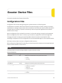
Configuration Files
184
Measurements / Strip Z
217
184
Measurements / Strip Width
218
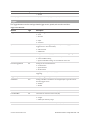
Trigger
185
Measurements / Strip Height
220
Layout
186
Measurements / Script
221
Calibration
186
Filters
187
Detection
222
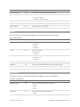
Sensors / Sensor
188
PartRegion
222
Sensors / Sensor / Profiling
188
PartRegion3D
223
Opening
Measurement Region
Output
Dashboard
Setup
Profile
Part
221
189
SurfaceCircleRegion
223
Area
190
SurfaceFeature3d
223
Feature
190
Measurements / PartArea
224
Line
191
Measurements / PartVolume
224
Anchor
191
Measurements / PartHeight
225
Measurements / Width
192
Measurements / PartEllipseMajor
226
Measurements / Height
192
Measurements / PartEllipseMinor
227
Measurements / Distance
193
Measurements / PartEllipseAngle
228
Measurements / PositionX
194
Measurements / PartEllipseRatio
228
Measurements / PositionZ
195
Measurements / PartBoundingBoxX
229
Measurements / CenterX
195
Measurements / PartBoundingBoxY
230
Measurements / CenterZ
196
Measurements / PartBoundingBoxWidth
231
Measurements / AngleX
197
Measurements / PartBoundingBoxLength
232
Measurements / IntersectX
198
Measurements / PartHoleX
233
Gocator 2000 & 2300 Series
5
Measurements / PartHoleY
234
Versions and Upgrades
268
Measurements / PartHoleZ
235
Data Types
269
Measurements / PartHoleRadius
236
Profile Sources
269
Measurements / PartOpeningX
237
Status Codes
270
Measurements / PartOpeningY
239
Command and Reply Formats
270
Measurements / PartOpeningZ
240
Result Format
270
Measurements / PartOpeningLength
242
Measurements / PartOpeningAngle
243
Measurements / PartStudTipX
244
Measurements / PartStudTipY
245
Measurements / PartStudTipZ
247
Get Protocol Version
273
Measurements / PartStudBaseX
248
Start Upgrade
273
Measurements / PartStudBaseY
249
Get Upgrade Status
273
Measurements / PartStudBaseZ
250
Get Upgrade Log
274
Measurements / PartStudBaseRadius
251
Control Commands
274
Measurements / SurfacePlaneXAngle
253
Get Protocol Version
274
Measurements / SurfacePlaneYAngle
253
Get System Info
275
Measurements / SurfacePlaneZOffset
254
Log In/Out
276
Measurements / PartPositionX
255
Change Password
277
Measurements / PartPositionY
256
Change Buddy
277
Measurements / PartPositionZ
256
Discovery Commands
271
Get Address
271
Set Address
272
Upgrade Commands
273
Get File List
278
Measurements / SurfaceTextureRoughness 257
Copy File
278
Measurements / SurfaceTextureInvalidCount
Read File
279
258
Write File
279
Measurements / Script
259
Delete File
279
259
Get Default File
280
Ethernet
259
Set Default File
280
Serial
261
Get Loaded File
281
Analog
262
Get Mode
281
DigitalOutput
262
Set Mode
282
264
Get Time
282
264
Get Encoder
282
265
Start
283
266
Scheduled Start
283
266
Stop
284
266
Trigger
284
Discovery
266
Scheduled Digital Output
284
Command Channels
267
Scheduled Analog Output
285
Result Channels
267
Ping
286
Modes
267
Reset
286
Buddy Communication Channels
268
Backup
287
States
268
Restore
287
Outputs
Calibration File
SysCal
Entries
Protocols
Gocator Protocol
Concepts
Gocator 2000 & 2300 Series
6
Restore Factory
287
Start
315
Get Connection Type
288
Stop
315
Set Connection Type
288
Trigger
316
Clear Calibration
289
Load Configuration
316
Data Results
289
Stamp
317
Video
290
Alignment Calibration
317
Profile
290
Travel Calibration
318
Profile Intensity
291
Clear Calibration
318
Part Profile
292
Data Commands
319
Part Intensity
292
Get Result
319
Alignment Calibration
293
Get Value
319
Travel Calibration
293
Get Decision
320
Exposure Calibration
293
Health Commands
321
Measurement
293
Get Health
321
Health Results
295
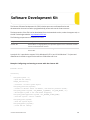
Software Development Kit
322
Modbus TCP Protocol
299
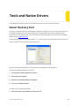
Tools and Native Drivers
324
Concepts
299
Sensor Recovery Tool
324
Messages
299
GenTL Driver
326
Registers
300
16-bit RGB Image
327
Control Registers
301
16-bit Grey Scale Image
328
Output Registers
302
Registers
330
Measurement Registers
304
XML Settings File
331
EtherNet/IP Protocol
305
CSV Converter Tool
332
Concepts
305
Troubleshooting
334
Basic Object
305
Specifications
336
Identity Object (Class 0x01)
305
Gocator 2000 Series
336
TCP/IP Object (Class 0xF5)
306
Gocator 2020
337
Ethernet Link Object (Class 0xF6)
306
Gocator 2030
338
Assembly Object (Class 0x04)
307
Gocator 2040
339
Command Assembly
307
Gocator 2050
341
Sensor State Assembly
308
Gocator 2070
343
Sample State Assembly
309
Gocator 2080
346
Extended Sample State Assembly
310
Gocator 2300 Series
348
312
Gocator 2330
349
312
Gocator 2340
351
Asynchronous and Polling Operation
312
Gocator 2350
352
Serial Communication
312
Gocator 2370
354
Command and Reply Format
313
Gocator 2380
357
Special Characters
313
Standard Result Format
314
Grounding Shield
361
Custom Result Format
314
Power
361
315
Laser Safety Input
361
ASCII Protocol
Ethernet Communication
Control Commands
Gocator 2000 & 2300 Series
Gocator 2000 I/O Connector
360
7
Digital Outputs
Inverting Outputs
361
362
Digital Inputs
362
Encoder Input
363
Serial Output
364
Analog Output
364
Gocator 2300 Power/LAN Connector
366
Grounding Shield
366
Power
367
Laser Safety Input
367
Gocator 2300 I/O Connector
368
Grounding Shield
369
Digital Outputs
369
Inverting Outputs
369
Digital Inputs
370
Encoder Input
370
Serial Output
371
Analog Output
371
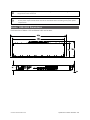
Master 100
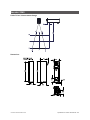
Master 100 Dimensions
Master 200
Master 200 Dimensions
Master 400/800
373
374
375
377
378
Master 400/800 Electrical Specifications
379
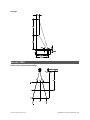
Master 400/800 Dimensions
380
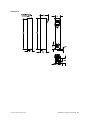
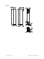
Master 1200/2400
381
Master 1200/2400 Electrical Specifications
382
Master 1200/2400 Dimensions
383
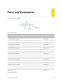
Parts and Accessories
384
Warranty and Return Policy
387
Software Licenses
388
Support
394
Contact
395
Gocator 2000 & 2300 Series
8
Introduction
The Gocator 2000 and 2300 series of laser profiling sensors is designed for 3D measurement and
control applications. Gocator sensors are configured using a web browser and can be connected to a
variety of input and output devices.
This documentation describes how to connect, configure, and use a Gocator. It also contains reference
information on the device's protocols and configuration files.
Notational Conventions
This guide uses the following notational conventions:
Follow these safety guidelines to avoid potential injury or property damage.
Consider this information in order to make best use of the product.
Gocator 2000 & 2300 Series
9
Safety and Maintenance
The following sections describe the safe use and maintenance of Gocator sensors.
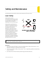
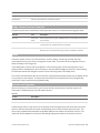
Laser Safety
Gocator sensors contain
semiconductor lasers that emit visible
or invisible light and are designated as
Class 2M, Class 3R, or Class 3B,
depending on the chosen laser option.
Gocator sensors are referred to as
components, indicating that they are
sold only to qualified customers for
incorporation into their own
equipment. These sensors do not
incorporate safety items that the
customer may be required to provide
in their own equipment (e.g., remote
interlocks, key control; refer to
references for detailed information).
As such, these sensors do not fully
comply with the standards relating to
laser products specified in IEC 60825-1
and FDA CFR Title 21 Part 1040.
Use of controls or adjustments or performance of procedures other than those specified herein
may result in hazardous radiation exposure.
References
1. International standard IEC 60825-1 (2001-08) consolidated edition, Safety of laser products – Part 1:
Equipment classification, requirements and user's guide.
2. Technical report 60825-10, Safety of laser products – Part 10. Application guidelines and explanatory
notes to IEC 60825-1.
3. Laser Notice No. 50, FDA and CDRH http://www.fda.gov/cdrh/rad-health.html
Gocator 2000 & 2300 Series
10
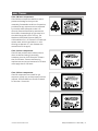
Laser Classes
Class 2M laser components
Class 2M laser components would not cause
permanent damage to the eye under
reasonably foreseeable conditions of operation,
provided that any exposure can be terminated
by the blink reflex (assumed to take 0.25
seconds). Because classification assumes the
blink reflex, the wavelength of light must be in
the visible range (400 nm to 700 nm). The
Maximum Permissible Exposure (MPE) for
visible radiation for 0.25 seconds is 25 watts per
square meter, which is equivalent to 1 mW
entering an aperture of 7 mm diameter (the
assumed size of the pupil).
Class 3R laser components
Class 3R laser products emit radiation where
direct intrabeam viewing is potentially
hazardous, but the risk is lower with 3R lasers
than for 3B lasers. Fewer manufacturing
requirements and control measures for 3R laser
users apply than for 3B lasers.
Class 3B laser components
Class 3B components are unsafe for eye
exposure. Usually only ocular protection will be
required. Diffuse reflections are safe if viewed
for less than 10 seconds.
Gocator 2000 & 2300 Series
Safety and Maintenance • Laser Safety • 11
Labels reprinted here are examples only. For accurate specifications, refer to the label on your
sensor.
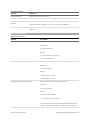
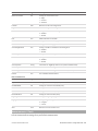
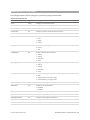
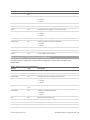
Precautions and Responsibilities
Precautions specified in IEC 60825-1 and FDA CFR Title 21 Part 1040 are as follows:
Requirement
Class 2M
Class 3R
Class 3B
Remote interlock
Not required
Not required
Required*
Key control
Not required
Not required
Required – cannot remove
key when in use*
Power-on delays
Not required
Not required
Required*
Beam attenuator
Not required
Not required
Required*
Emission indicator
Not required
Not required
Required*
Warning signs
Not required
Not required
Required*
Beam path
Not required
Terminate beam at useful
length
Terminate beam at useful
length
Specular reflection
Not required
Prevent unintentional
reflections
Prevent unintentional
reflections
Eye protection
Not required
Not required
Required under special
conditions
Laser safety officer
Not required
Not required
Required
Training
Not required
Required for operator and
maintenance personnel
Required for operator and
maintenance personnel
*LMI Class 3B laser components do not incorporate these laser safety items. These items must be added and completed by customers
in their system design.
Class 3B Responsibilities
LMI Technologies has filed reports with the FDA to assist customers in achieving certification of laser
products. These reports can be referenced by an accession number, provided upon request. Detailed
descriptions of the safety items that must be added to the system design are listed below.
Remote Interlock
A remote interlock connection must be present in Class 3B laser systems. This permits remote switches
to be attached in serial with the keylock switch on the controls. The deactivation of any remote switches
must prevent power from being supplied to any lasers.
Key Control
A key operated master control to the lasers is required that prevents any power from being supplied to
the lasers while in the OFF position. The key can be removed in the OFF position but the switch must not
allow the key to be removed from the lock while in the ON position.
Gocator 2000 & 2300 Series
Safety and Maintenance • Laser Safety • 12
Power-On Delays
A delay circuit is required that illuminates warning indicators for a short period of time before supplying
power to the lasers.
Beam Attenuators
A permanently attached method of preventing human access to laser radiation other than switches,
power connectors or key control must be employed. On some LMI laser sensors, the beam attenuator is
supplied with the sensor as an integrated mechanical shutter.
Emission Indicator
It is required that the controls that operate the sensors incorporate a visible or audible indicator when
power is applied and the lasers are operating. If the distance between the sensor and controls is more
than 2 meters, or mounting of sensors intervenes with observation of these indicators, then a second
power-on indicator should be mounted at some readily-observable position. When mounting the
warning indicators, it is important not to mount them in a location that would require human exposure
to the laser emissions. User must ensure that the emission indicator, if supplied by OEM, is visible when
viewed through protective eyewear.
Warning Signs
Laser warning signs must be located in the vicinity of the sensor such that they will be readily observed.
Examples of laser warning signs are as follows:
FDA warning sign example
IEC warning sign example
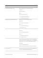
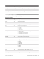
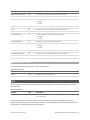
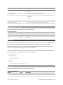
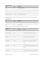
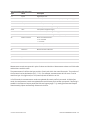
Nominal Ocular Hazard Distance (NOHD)
This is the distance from the source at which the intensity or the energy per surface unit becomes lower
than the Maximum Permissible Exposure (MPE) on the cornea and on the skin. The laser beam is
considered dangerous if the operator is closer from the source than the NOHD.
The following table shows the estimated NOHD for each Gocator model and laser class, assuming
continuous operation of the laser. As a configurable device the Gocator allows the user to set the laser
exposure (laser on-time) independently of the frame period (total cycle time for data acquisition).
Continuous operation of the laser means that the laser exposure is configured to be identical to the
frame period, which is also referred to as 100% duty cycle. However, in many applications the laser
exposure can be smaller than the frame period (less than 100% duty cycle) thereby reducing the NOHD.
Gocator 2000 & 2300 Series
Safety and Maintenance • Laser Safety • 13
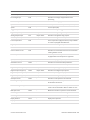
The table therefore shows the worst-case NOHD.
Model
Laser Class
Line Fan Angle
NOHD (mm)
2x20
2M
28
259
2x30
2M
28
259
3R
28
900
3B
28
5759
2M
28
259
3R
28
900
3B
28
5759
2M
28
259
3R
28
900
3B
28
5759
2M
43
251
3R
43
875
3B
43
3645
2M
57
245
3R
57
859
3B
57
2645
2x40
2x50
2x70
2x80
Systems Sold or Used in the USA
Systems that incorporate laser components or laser products manufactured by LMI Technologies
require certification by the FDA.
Customers are responsible for achieving and maintaining this certification.
Customers are advised to obtain the information booklet Regulations for the Administration and
Enforcement of the Radiation Control for Health and Safety Act of 1968: HHS Publication FDA 88-8035.
This publication, containing the full details of laser safety requirements, can be obtained directly from
the FDA, or downloaded from their web site at http://www.fda.gov/cdrh.
Electrical Safety
Failure to follow the guidelines described in this section may result in electrical shock or
equipment damage.
Sensors should be connected to earth ground
All sensors should be connected to earth ground through their housing. All sensors should be mounted
on an earth grounded frame using electrically conductive hardware to ensure the housing of the sensor
is connected to earth ground. Use a multi-meter to check the continuity between the sensor connector
and earth ground to ensure a proper connection.
Gocator 2000 & 2300 Series
Safety and Maintenance • Electrical Safety • 14
Minimize voltage potential between system ground and sensor ground
Care should be taken to minimize the voltage potential between system ground (ground reference for
I/O signals) and sensor ground. This voltage potential can be determined by measuring the voltage
between Analog_out- and system ground. The maximum permissible voltage potential is 12 V but should
be kept below 10 V to avoid damage to the serial and encoder connections.
See Gocator 2000 I/O Connector (page 360) and See Gocator 2300 I/O Connector (page 368) for a
description of connector pins.
Use a suitable power supply
The +24 to +48 VDC power supply used with Gocator sensors should be an isolated supply with inrush
current protection or be able to handle a high capacitive load.
Use care when handling powered devices
Wires connecting to the sensor should not be handled while the sensor is powered. Doing so may cause
electrical shock to the user or damage to the equipment.
Environment and Lighting
Avoid strong ambient light sources
The imager used in this product is highly sensitive to ambient light hence stray light may have adverse
effects on measurement. Do not operate this device near windows or lighting fixtures that could
influence measurement. If the unit must be installed in an environment with high ambient light levels, a
lighting shield or similar device may need to be installed to prevent light from affecting measurement.
Avoid installing sensors in hazardous environments
To ensure reliable operation and to prevent damage to Gocator sensors, avoid installing the sensor in
locations
l
that are humid, dusty, or poorly ventilated;
l
with a high temperature, such as places exposed to direct sunlight;
l
where there are flammable or corrosive gases;
l
where the unit may be directly subjected to harsh vibration or impact;
l
where water, oil, or chemicals may splash onto the unit;
l
where static electricity is easily generated.
Ensure that ambient conditions are within specifications
Gocator sensors are suitable for operation between 0–50° C and 25–85% relative humidity (noncondensing). Measurement error due to temperature is limited to 0.015% of full scale per degree C.
The Master 200/400/800/1200/2400 is similarly rated for operation between 0–50° C.
The storage temperature is -30–70° C.
The sensor must be heat-sunk through the frame it is mounted to. When a sensor is properly
heat sunk, the difference between ambient temperature and the temperature reported in the
sensor's health channel is less
than 15° C.
Gocator 2000 & 2300 Series
Safety and Maintenance • Environment and Lighting • 15
Gocator sensors are high-accuracy devices, and the temperature of all of its components must
therefore be in equilibrium. When the sensor is powered up, a warm-up time of at least one
hour is required to reach a consistent spread of temperature in the sensor.
Sensor Maintenance
Keep sensor windows clean
Gocator sensors are high-precision optical instruments. To ensure the highest accuracy is achieved in all
measurements, the windows on the front of the sensor should be kept clean and clear of debris.
Use care when cleaning sensor windows
Use dry, clean air to remove dust or other dirt particles. If dirt remains, clean the windows carefully with
a soft, lint-free cloth and non-streaking glass cleaner or isopropyl alcohol. Ensure that no residue is left
on the windows after cleaning.
Turn off lasers when not in use
LMI Technologies uses semiconductor lasers in 3D measurement sensors. To maximize the lifespan of
the sensor, turn off the laser when not in use.
Avoid excessive modifications to files stored on the sensor
Settings for Gocator sensors are stored in flash memory inside the sensor. Flash memory has an
expected lifetime of 100,000 writes. To maximize lifetime, avoid frequent or unnecessary file save
operations.
Gocator 2000 & 2300 Series
Safety and Maintenance • Sensor Maintenance • 16
Getting Started
The following sections provide system and hardware overviews, in addition to installation and setup
procedures.
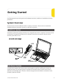
System Overview
Gocator sensors can be installed and used in a variety of scenarios. Sensors can be connected as
standalone devices, dual-sensor systems, or multi-sensor systems.
Standalone System
Standalone systems are typically used when only a single Gocator sensor is required. The sensor can be
connected to a computer's Ethernet port for setup and can also be connected to devices such as
encoders, photocells, or PLCs.
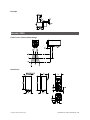
Dual-Sensor System
In a dual-sensor system, two Gocator sensors work together to perform profiling and output the
combined results. The controlling sensor is referred to as the Main sensor, and the other sensor is
referred to as the Buddy sensor. Gocator's software recognizes three installation orientations: None
(Isolated), Opposite and Wide.
Gocator 2000 & 2300 Series
17
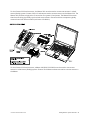
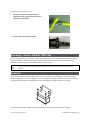
For the Gocator 2000 series sensors, the Master 200 must be used to connect two sensors in a dualsensor (Buddy) system. Gocator 20x0 I/O cordsets are used to connect sensors to the Master 200. The
Master 200 provides a single point of connection for system I/O and power. The Master 200 ensures
that the scan timing is precisely synchronized across sensors. Sensors and client computers typically
communicate via an Ethernet switch (minimum 100 Mbit/s).
For the Gocator 2300 series sensors, a Master 400/800/1200/2400 must be used to connect two
sensors in a dual-sensor (Buddy) system. Gocator 23x0 Master cordsets are used to connect sensors to
the Master.
Gocator 2000 & 2300 Series
Getting Started • System Overview • 18
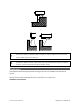
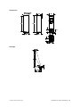
Multi-Sensor System
Master 400/800/1200/2400 networking hardware can be used to connect two or more sensors into a
multi-sensor system. Gocator Master cordsets are used to connect the sensors to a Master. The Master
provides a single point of connection for power, safety, encoder, and digital inputs. A Master
400/800/1200/2400 can be used to ensure that the scan timing is precisely synchronized across
sensors. Sensors and client computers communicate via an Ethernet switch (minimum 100 Mbit/s).
Unlike the Master 200, Master 400/800/1200/2400 does not support digital, serial, or analog output.
Gocator 2000 & 2300 Series
Getting Started • System Overview • 19
Gocator 2000 & 2300 Series
Getting Started • System Overview • 20
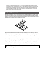
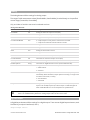
Hardware Overview
The following sections describe Gocator and its associated hardware.
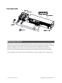
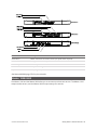
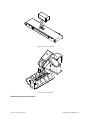
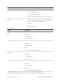
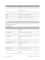
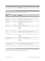
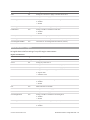
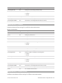
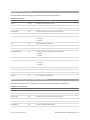
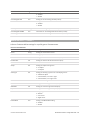
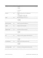
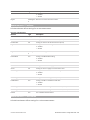
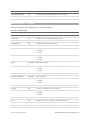
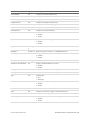
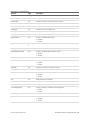
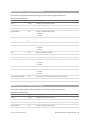
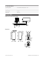
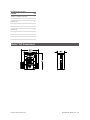
Gocator 2000 Sensor
Item
Description
Camera
Observes laser light reflected from target surfaces.
Laser Emitter
Emits structured light for laser profiling.
I/O Connector
Accepts power and input/output signals.
LAN Connector
Connects to 100 Mbit/s Ethernet network.
Power Indicator
Illuminates when power is applied (blue).
Range Indicator
Illuminates when camera detects laser light and is within the target range (green).
Laser Indicator
Illuminates when laser safety input is active (amber).
Serial Number
Unique sensor serial number.
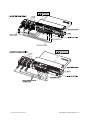
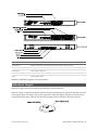
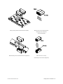
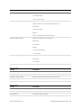
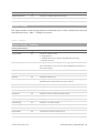
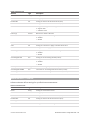
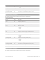
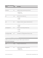
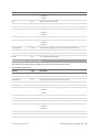
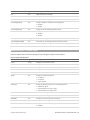
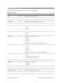
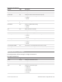
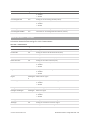
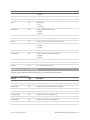
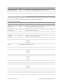
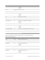
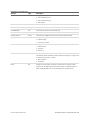
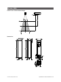
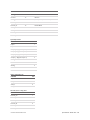
Gocator 2300 Sensor
Gocator 2000 & 2300 Series
Getting Started • Hardware Overview • 21
Item
Description
Camera
Observes laser light reflected from target surfaces.
Laser Emitter
Emits structured light for laser profiling.
I/O Connector
Accepts input and output signals.
Power / LAN Connector
Accepts power and laser safety signals and connects to 1000 Mbit/s Ethernet network.
Power Indicator
Illuminates when power is applied (blue).
Range Indicator
Illuminates when camera detects laser light and is within the target range (green).
Laser Indicator
Illuminates when laser safety input is active (amber).
Serial Number
Unique sensor serial number.
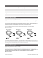
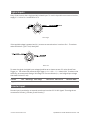
Gocator 2000 Cordsets
Gocator 2000 sensors use three types of cordsets.
The Ethernet cordset is used for sensor communication via 100 Mbit/s Ethernet over a standard RJ45
connector.
The Gocator I/O cordset provides power and laser safety interlock to sensors. It also provides digital I/O
connections, an encoder interface, RS-485 serial connection, and an analog output.
The Gocator Master cordset provides electrical connection between the sensor and a Master
400/800/1200/2400
The maximum cordset length is 60 meters. See Gocator 2000 I/O Connector (page 360) for pinout details.
See Parts and Accessories (page 384) for cordset lengths and part numbers. Contact LMI for information
on creating cordsets with customized lengths and connector orientations.
Gocator 2300 Cordsets
Gocator 2300 sensors use two types of cordsets.
The Power & Ethernet cordset provides power, laser safety interlock to the sensor. It is also used for
sensor communication via 1000 Mbit/s Ethernet with a standard RJ45 connector. The Master version of
the Power & Ethernet cordset provides direct connection between the sensor and a Master
400/800/1200/2400.
Gocator 2000 & 2300 Series
Getting Started • Hardware Overview • 22
The Gocator I/O cordset provides digital I/O connections, an encoder interface, RS-485 serial connection,
and an analog output.
The maximum cordset length is 60 m. See Gocator 2300 I/O Connector (page 368) and Gocator 2300
Power/LAN Connector on page 366 for pinout details.
See Parts and Accessories (page 384) for cordset lengths and part numbers. Contact LMI for information
on creating cordsets with customized lengths and connector orientations.
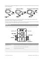
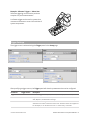
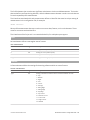
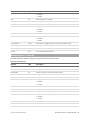
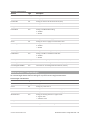
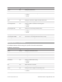
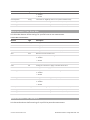
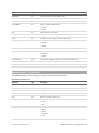
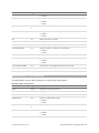
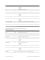
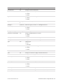
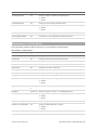
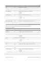
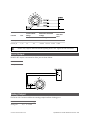
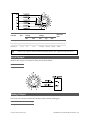
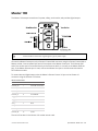
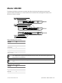
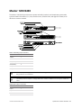
Master 100
The Master 100 is used by the Gocator 2300 seriesGocator 3100 series for standalone system setup.
Item
Description
Master Ethernet Port
Connects to the RJ45 connector labeled Ethernet on the Power/LAN to Master cordset.
Master Power Port
Connects to the RJ45 connector labeled Power/Sync on the Power/LAN to Master cordset. Provides power and laser safety to the Gocator.
Sensor I/O Port
Connects to the Gocator I/O cordset.
Master Host Port
Connects to the host PC's Ethernet port.
Power
Accepts power (+48 V).
Gocator 2000 & 2300 Series
Getting Started • Hardware Overview • 23
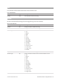
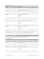
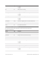
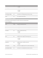
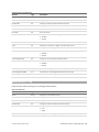
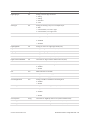
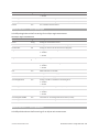
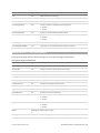
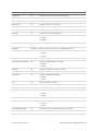
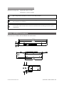
Item
Description
Power Switch
Toggles sensor power.
Laser Safety Switch
Toggles laser safety signal provided to the sensors [O= laser off, I= laser on].
Trigger
Signals a digital input trigger to the Gocator.
Encoder
Accepts encoder A, B and Z signals.
Digital Output
Provides digital output.
See Master 100 (page 373) for pinout details.
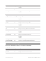
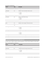
Master 200
The Master 200 supports standalone or dual-sensor setup. It is only used by the Gocator 2000 series.
Item
Description
Connection to Sensor 2
Gocator I/O connection for Sensor 2 (Buddy sensor).
Connection to Sensor 1
Gocator I/O connection for Sensor 1 (Main sensor).
Laser Safety Switch
Toggles laser safety signal provided to the sensors [O= laser off, I= laser on].
Power Switch
Toggles sensor power.
Input/Output
Accepts digital input and provides digital output, serial output, and analog output.
Encoder (Port 1 only)
Accepts encoder for Standalone sensor operation (Main sensor only).
Encoder (Port 1 & 2)
Accepts encoder for Dual Sensor operation (Main and Buddy sensors).
Power and Laser Safety
Accepts power (+24 to +48 V at 10 Watts) and laser safety inputs.
See Master 200 (page 375) for pinout details.
Master 400/800
The Master 400 and the Master 800 allow you to connect more than two sensors. The Master 400
accepts four sensors, and the Master 800 accepts eight sensors.
Gocator 2000 & 2300 Series
Getting Started • Hardware Overview • 24
Item
Description
Sensor Ports
Master connection for Gocator sensors (no specific order required).
Ground Connection
Earth ground connection point.
Laser Safety
Laser safety connection.
Encoder
Accepts encoder signal.
Input
Accepts digital input.
See Master 400/800 (page 378) for pinout details.
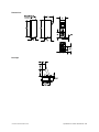
Master 1200/2400
The Master 1200 and the Master 2400 allow you to connect more than two sensors. The Master 1200
accepts twelve sensors, and the Master 2400 accepts twenty-four sensors.
Gocator 2000 & 2300 Series
Getting Started • Hardware Overview • 25
Item
Description
Sensor Ports
Master connection for Gocator sensors (no specific order required).
Ground Connection
Earth ground connection point.
Laser Safety
Laser safety connection.
Encoder
Accepts encoder signal.
Input
Accepts digital input.
See Master 1200/2400 (page 381) for pinout details.
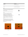
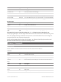
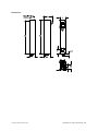
Calibration Targets
Calibration targets are used for alignment calibration or travel calibration.
Calibration disks are typically used with systems containing a single sensor and can be ordered from LMI
Technologies. When choosing a disk for your application, select the largest disk that fits entirely within
the required field of view. See Parts and Accessories (page 384) for calibration disk part numbers.
Gocator 2000 & 2300 Series
Getting Started • Hardware Overview • 26
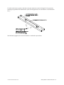
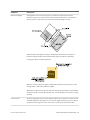
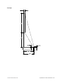
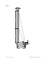
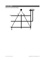
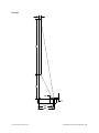
For wide, multi-sensor systems, calibration bars are required to match the length of the system by
following the guidelines illustrated below. (LMI Technologies does not manufacture or sell calibration
bars.)
See Calibration (page 83) for more information on calibration procedures.
Gocator 2000 & 2300 Series
Getting Started • Hardware Overview • 27
Installation
The following sections provide grounding, mounting, and orientation information.
Grounding - Gocator
Gocators should be grounded to the earth/chassis through their housings and through the grounding
shield of the Power I/O cordset. Gocator sensors have been designed to provide adequate grounding
through the use of M5 x 0.8 pitch mounting screws. Always check grounding with a multi-meter to
ensure electrical continuity between the mounting frame and the Gocator's connectors.
The frame or electrical cabinet that the Gocator is mounted to must be connected to earth
ground.
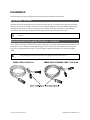
Recommended Grounding Practices - Cordsets
If you need to minimize interference with other equipment, you can ground the Power & Ethernet or the
Power & Ethernet to Master cordset (depending on which cordset you are using) by terminating the
shield of the cordset before the split. The most effective grounding method is to use a 360-degree
clamp.
The grounding practices described here only apply to Gocator 23xx sensors.
Gocator 2000 & 2300 Series
Getting Started • Installation • 28
To terminate the cordset's shield:
1.
Expose the cordset's braided shield by
cutting the plastic jacket before the point
where the cordset splits.
2.
Install a 360-degree ground clamp.
Grounding - Master 400/800/1200/2400
The mounting brackets of all Masters have been designed to provide adequate grounding through the
use of star washers. Always check grounding with a multi-meter by ensuring electrical continuity
between the mounting frame and RJ45 connectors on the front.
The frame or electrical cabinet that the Master is mounted to must be connected to earth
ground.
Mounting
Sensors should be mounted using four M5 x 0.8 pitch screws of suitable length. The recommended
thread engagement into the housing is 8 - 10 mm. Proper care should be taken in order to ensure that
the internal threads are not damaged from cross-threading or improper insertion of screws.
Sensors should not be installed near objects that might occlude a camera's view of the laser.
Gocator 2000 & 2300 Series
Getting Started • Installation • 29
Sensors should not be installed near surfaces that might create unanticipated laser reflections.
The sensor must be heat sunk through the frame it is mounted to. When a sensor is properly
heat sunk, the difference between ambient temperature and the temperature reported in the
sensor's health channel is less than 15° C.
Gocator sensors are high-accuracy devices. The temperature of all of its components must be
in equilibrium. When the sensor is powered up, a warm-up time of at least one hour is required
to reach a consistent spread of temperature within the sensor.
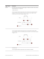
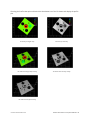
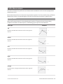
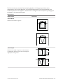
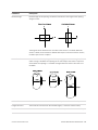
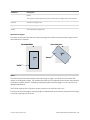
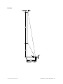
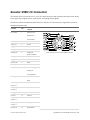
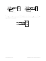
Orientations
The examples below illustrate the possible mounting orientations for standalone and dual-sensor
systems.
See Dual-Sensor System Layout (page 82) for more information on orientations.
Standalone Orientations:
Gocator 2000 & 2300 Series
Getting Started • Installation • 30
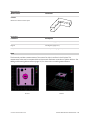
Single sensor above conveyor
Single sensor on robot arm
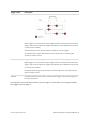
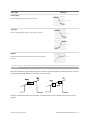
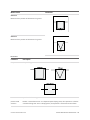
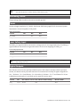
Dual-Sensor System Orientations:
Gocator 2000 & 2300 Series
Getting Started • Installation • 31
Side-by-side for wide-area measurement (Wide)
Main must be on the left side (when
looking into the connector)
of the Buddy (Wide)
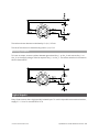
Above/below for two-sided measurement (Opposite)
Main must be on the top
with Buddy on the bottom (Opposite)
Gocator 2000 & 2300 Series
Getting Started • Installation • 32
Network Setup
The following sections provide procedures for client PC and Gocator network setup.
Client Setup
Sensors are shipped with the following default network configuration:
Setting
Default
DHCP
Disabled
IP Address
192.168.1.10
Subnet Mask 255.255.255.0
Gateway
0.0.0.0
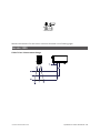
All Gocator sensors are configured to 192.168.1.10 as the default IP address. For a dual-sensor
system, the Main and Buddy sensors must be assigned unique addresses before they can be
used on the same network. Before proceeding, connect the Main and Buddy sensors one at a
time (to avoid an address conflict) and use the steps in Running a Dual-Sensor System on page
37 to assign each sensor a unique address.
To connect to a sensor for the first time:
1.
Connect cables and apply power.
Sensor cabling is illustrated in System
Overview on page 17.
Gocator 2000 & 2300 Series
Getting Started • Network Setup • 33
2.
Change the client PC's network settings.
Windows 7
l
Open the Control Panel and select
Network and Sharing Center, then click
Change Adapter Settings.
l
Right-click the desired network
connection, and then click Properties.
l
On the Networking tab, click Internet
Protocol Version 4 (TCP/IPv4), and then
click Properties.
l
Select the Use the following IP address
option.
l
Enter IP Address "192.168.1.5" and Subnet
Mask "255.255.255.0", then click OK.
Mac OS X v10.6
l
Open the Network Pane in System
Preferences and select Ethernet.
l
Set Configure to Manually.
l
Enter IP Address "192.168.1.5" and Subnet
Mask "255.255.255.0", then click Apply.
See Troubleshooting (page 334) if you experience any problems while attempting to establish a
connection to the sensor.
Gocator 2000 & 2300 Series
Getting Started • Network Setup • 34
Gocator Setup
The Gocator is shipped with a default configuration that will produce laser profiles on most targets.
The following sections walk you through the steps required to set up a standalone sensor system and a
dual-sensor system for operations. After you have completed the setup, you can perform laser profiling
to verify basic sensor operation.
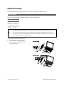
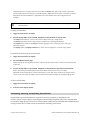
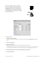
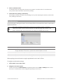
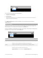
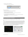
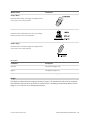
Running a Standalone Sensor System
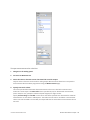
To configure a standalone sensor system:
1.
Power up the sensor.
The power indicator (blue) should turn on immediately.
2.
Enter the sensor's IP address (192.168.1.10) in a
web browser.
3.
Log in as Administrator with no password.
The interface display language can be changed using
the language option. After selecting the language, the
browser will refresh and the web interface will display in
the selected language.
4.
Select the Connection page.
Gocator 2000 & 2300 Series
Getting Started • Network Setup • 35
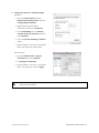
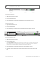
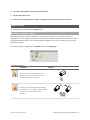
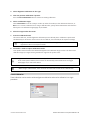
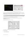
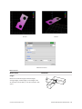
5.
Choose a Connect To setting.
The Connect To setting specifies whether the sensor
system is standalone or connected to a Master
200/400/800/1200/2400. For single-sensor operations,
select Standalone or Master 200.
6.
Ensure that the Data Source selector is showing
LIVE.
7.
Ensure that the Laser Safety Switch is enabled or
the Laser Safety input is high.
8.
Select the Setup page.
9.
Press the Start button to start the sensor.
The Start button is used to run sensors continuously,
whereas the Snapshot button is used to trigger a single
capture.
Master 200
Standalone
Master 400/800/1200/2400
Gocator 2000 & 2300 Series
Getting Started • Network Setup • 36
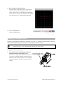
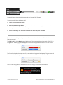
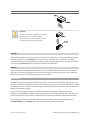
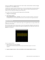
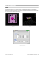
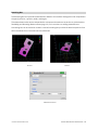
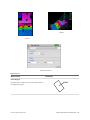
10. Move a target into the laser plane.
If a target object is within the sensor's measurement
range, the data viewer will display the shape of the
target, and the sensor's range indicator will illuminate.
If you cannot see the laser, or if a profile is not displayed
in the Data Viewer, see Troubleshooting (page 334).
11. Press the Stop button.
The laser should turn off.
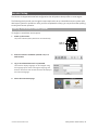
Running a Dual-Sensor System
All sensors are shipped with a default IP address of 192.168.1.10. Ethernet networks require a unique IP
address for each device, so you must set up a unique address for each sensor.
If Master 200 is used and an encoder input is required, the encoder signals must be connected
to the Encoder (port 1 & 2). See Master 200 (page 375) for more details.
To configure a dual-sensor system:
1.
Turn off the sensors and unplug the Ethernet
network connection of the Main sensor.
All sensors are shipped with a default IP address of
192.168.1.10. Ethernet networks require a unique IP
address for each device. Skip step 1 to 3 if the Buddy
sensor's IP address is already set up with an unique
address.
Gocator 2000 & 2300 Series
Getting Started • Network Setup • 37
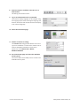
2.
Power up the Buddy sensor.
The power LED (blue) of the Buddy sensor should turn
on immediately.
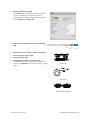
3.
Enter the sensor's IP address 192.168.1.10 in a
web browser.
This will log into the Buddy sensor.
4.
Log in as Administrator with no password.
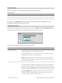
5.
Select the Connection Page.
6.
Modify the IP address to 192.168.1.11 in the
Network settings and click the Save button.
When you click the Save button, you will be prompted
to confirm your selection.
7.
Turn off the sensors, re-connect the Main sensor's
Ethernet connection and power-cycle the sensors.
After changing network configuration, the sensors
must be reset or power-cycled before the change will
take effect.
Gocator 2000 & 2300 Series
Getting Started • Network Setup • 38
8.
Enter the sensor's IP address 192.168.1.10 in a
web browser.
This will log into the Main sensor.
9.
Log in as Administrator with no password.
The interface display language can be changed using
the language option. After selecting the language, the
browser will refresh and the web interface will display
in the selected language.
10. Select the Connection page.
11. Choose a Connect To setting.
The Connect To setting specifies whether the sensor
system is standalone or connected to a Master 200 or
a Master 400/800/1200/2400. For dual-sensor
operations, select Master 200 or Master
400/800/1200/2400.
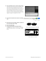
12. Go to Connection page and select the Available
Sensors panel.
The serial number of the Buddy sensor is listed in the
Available Sensors panel.
Gocator 2000 & 2300 Series
Getting Started • Network Setup • 39
13. Select the Buddy sensor. Click the Assign button.
The Buddy sensor will be assigned to the Main sensor
and its status will be updated in the System panel.
The firmware on Main and Buddy sensors must be the
same for Buddy assignment to be successful. If the
firmware is different, connect the Main and Buddy
sensor one at a time and follow the steps in Firmware
Upgrade on page 63 to upgrade the sensors.
14. Ensure that the Data Source selector is showing
LIVE.
15. Ensure that the Laser Safety Switch is enabled or
the Laser Safety input is high.
16. Select the Setup page.
17. Press the Start button to start the sensors.
The Start button is used to run sensors continuously,
while the Snapshot button is used to trigger a single
profile.
Master 400/800/1200/2400 (for Gocator 2300)
Master 200 (for Gocator 2000)
Gocator 2000 & 2300 Series
Getting Started • Network Setup • 40
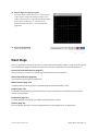
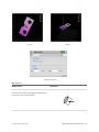
18. Move a target into the laser plane.
If a target object is within the sensor's measurement
range, the data viewer will display the shape of the
target, and the sensor's range indicator will illuminate.
If you cannot see the laser, or if a profile is not
displayed in the Data Viewer, see Troubleshooting
(page 334).
19. Press the Stop button.
The laser should turn off.
Next Steps
After you complete the steps in this section, the Gocator measurement system is ready to be configured
for an application using the software interface. The interface is explained in the following sections:
Connection and Maintenance (page 57)
Sets up the sensor connections, networking and performs maintenance tasks.
Setup and Calibration (page 65)
Fine-tunes laser profiling for an application. Measurement (page 100)
Programs measurements on sensors that are equipped with measurement tools.
Output (page 170)
Profile data, measurements, and Pass/Fail results can be transmitted to external devices for process
control or data analysis.
Dashboard (page 181)
Provides real-time monitoring of its health and measurement results.
Toolbar (page 49)
Controls system operation, record and playback data, and manages sensor configurations.
Gocator 2000 & 2300 Series
Getting Started • Next Steps • 41
Theory of Operation
The following sections describe the theory of operation of Gocator sensors.
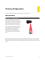
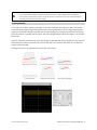
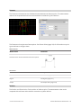
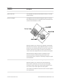
3D Acquisition
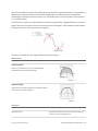
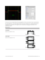
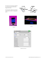
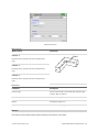
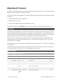
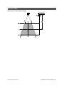
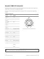
Principle of 3D Acquisition
The Gocator 2000 and 2300 series are line
profiler sensors, meaning that they capture a
single 3D profile for each camera exposure. The
sensor projects a laser line onto the target. The
sensor's camera views the laser from an angle,
and captures the reflection of the light off the
target. Because of this triangulation angle, the
laser line appears in different positions on the
camera depending on the 3D shape of the
target. Gocator sensors are always precalibrated to deliver 3D data in engineering
units throughout the specified measurement
range.
Target objects are typically moved under the sensor on a transportation mechanism, such as a conveyor
belt. The sensor captures a series of 3D slices, building up the full scan of the object. Sensor speed and
required exposure time to measure the target are typically critical factors in applications with line profiler
sensors.
Gocator 2000 & 2300 Series
42
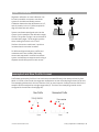
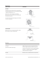
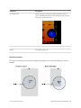
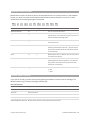
Resolution and Accuracy
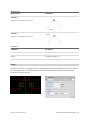
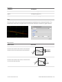
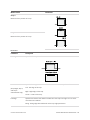
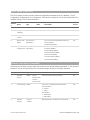
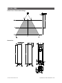
X Resolution
X resolution is the horizontal distance between
each measurement point along the laser line.
This specification is essentially based on the
number of camera columns used to cover the
field of view (FOV) at a particular measurement
range .
Since the FOV is trapezoidal, the distance
between points is closer at the near range than
at the far range. This is reflected in the Gocator
data sheet as the two numbers quoted for X
Resolution.
X Resolution is important for how accurate the
width of a target can be measured.
NOTE: When the Gocator runs in Profile Mode,
the 3D data is resampled to an X interval that is
different from the raw camera resolution.
Gocator 2000 & 2300 Series
Theory of Operation • 3D Acquisition • 43
Z Resolution
Z resolution is the variability of the height
measurement, in each individual 3D point, with
the target at a fixed position. This variability is
caused by camera imager and sensor
electronics.
Like X resolution, the Z resolution is better at
the close range and worse at the far range. This
is reflected in the Gocator data sheet as the two
numbers quoted for Z resolution.
Z Resolution gives an indication of the smallest
detectable height difference.
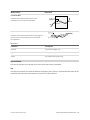
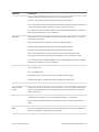
Z Linearity
Z Linearity is the difference between the actual
distance to the target and the measured
distance to the target, throughout the
measurement range.
Z Linearity is expressed in the Gocator data
sheet as a percentage of the total
measurement range.
Z Linearity gives an indication of the sensor's
ability to measure absolute distance
Gocator 2000 & 2300 Series
Theory of Operation • 3D Acquisition • 44
Profile Output
Gocator measures the height of the object calculated from laser triangulation. The Gocator reports a
series of ranges along the laser line, with each range representing the distance from the sensor's origin
plane. Each range contains a height and a position in the sensor's field of view. Coordinate Systems
Range data is reported in sensor or system coordinates depending on the calibration state. The
coordinate systems are described below.
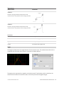
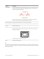
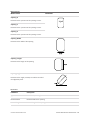
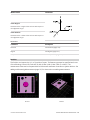
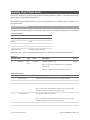
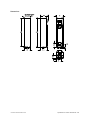
Sensor Coordinates
Before calibration, individual sensors use the
coordinate system shown here.
The Z axis represents the sensor's measurement
range (MR), with the values increasing towards the
sensor.
The X axis represents the sensor's field of view
(FOV).
The origin is at the center of the MR and FOV.
In Part data, the Y axis represents the relative
position of the part in the direction of travel.
Y position increases as the object moves forward
(increasing encoder position).
Gocator 2000 & 2300 Series
Theory of Operation • Profile Output • 45
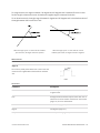
System Coordinates
Alignment calibration or travel calibration can
be used to establish a common coordinate
system for the Main and Buddy sensors.
Calibration determines the adjustments to X, Z,
and tilt (rotation in the X–Z plane) required to
align the data from each sensor.
System coordinates are aligned such that the
system X axis is parallel to the calibration target
surface. The system Z origin is set to the base of
the calibration target. The tilt angle is positive
when rotating from the X to the Z axis.
Similar to the sensor coordinates, Y positions
increase when the encoder increases.
For Wide and Opposite layouts, profiles and
measurements from the Main and Buddy
sensors are expressed in a unified coordinate
system. Isolated layouts express results using a
separate coordinate system for each sensor.
Resampled and Raw Profile Format
Profile data produced by Profile or Part mode are processed differently than data produced by Raw
Mode. In Profile or Part mode, the ranges are resampled to an even interval along the laser line (X axis).
The resampling divides the X axis into fixed-size "bins" at even intervals. Profile points that fall into the
same bin will be combined into a single range value (Z). The size of the resampling interval can be
configured in the see Filters Panel (page 88).
Gocator 2000 & 2300 Series
Theory of Operation • Profile Output • 46
In the Ethernet data channel, only the range values (Z) are reported and the X positions can be
reconstructed through the array index at the receiving end (the client).
Resampling reduces the complexity for downstream algorithms to process the profile data from the
Gocator, but at the cost of higher processing load on the sensor's CPU. In contrast, Raw mode outputs unprocessed range data. Ranges are reported in (X, Z) coordinate pairs,
freeing up processing resources in the Gocator, but typically requiring more complicated processing on
the client side.
All built-in measurement tools in the Gocator operate on resampled data in Profile or Part mode.
Gocator 2000 & 2300 Series
Theory of Operation • Profile Output • 47
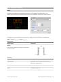
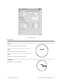
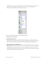
Gocator Web Interface
The following sections describe the Gocator web interface.
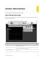
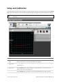
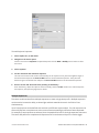
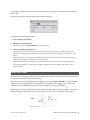
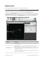
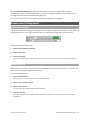
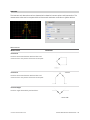
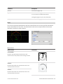
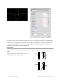
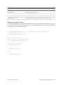
User Interface Overview
Gocator sensors are configured by connecting to a Main sensor with a web browser. The Gocator web
interface is illustrated below.
1
Element
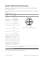
Description
Connection page
Contains settings for network configuration and maintenance. See Connection
and Maintenance (page 57) .
2
Setup page
Contains settings for trigger source, exposure, and performing calibration
steps. See Setup and Calibration (page 65) .
3
Measurement page
Contains built-in measurement tools and their settings. See Measurement
(page 100) .
Gocator 2000 & 2300 Series
48
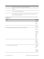
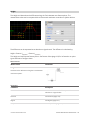
Element
Description
4
Output page
Contains settings for configuring output protocols used to communicate
measurements to external devices. See Output (page 170) .
5
Dashboard
Provides monitoring of measurement statistics and sensor health. See
Dashboard (page 181) .
6
Metrics panel
Summarizes important performance statistics. See Metrics Panel (page 55) .
7
Help
Provides online help resources (including user manual), firmware updates, and
SDK.
8
Toolbar
Controls sensor operation, manages configurations, and replays recorded
measurement data. See Toolbar (below) .
9
Configuration area
Provides controls to configure profiling and measurement parameters.
10
Data viewer
Displays sensor data, tool setup controls, and measurements. See Data Viewer
on page 92 for its use when the Setup page is active and on page 103 for its
use when the Measurement page is active.
Common Elements
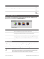
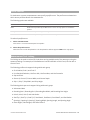
Toolbar
The toolbar is the central place for performing common operations. This section explains how to use the
toolbar to manage the sensor configurations and to operate the sensor.
Element
Description
1 Configuration Controls
Use the configuration controls to manage sensor settings.
2 Recorded Data Controls
Use the recorded data controls to download, export, and upload
recorded data.
3 Sensor Operation / Replay Control
Use the sensor operation controls to start sensors, enable recording, and control recorded data.
4 Data Source
Use the Data Source button to switch the sensor between live
and replay mode.
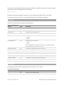
Saving and Loading Settings
When you change sensor settings using the Gocator web interface, some changes are saved
automatically, while other changes are temporary until you take action to save them. The following table
lists the types of information that can be saved in a sensor.
Setting Type
Behavior
Network Address
Network address changes are saved when you click the Save button in the Main panel
Gocator 2000 & 2300 Series
Gocator Web Interface • User Interface Overview • 49
Setting Type
Behavior
on the Connections page. The sensor must be reset before changes take effect.
Configuration
Most of the settings that can be changed in the Gocator's web interface, such as those
shown on the Setup , Measurement, and Output pages, are temporary until saved in a
configuration file. Each sensor can have multiple configuration files. If there is a
configuration file that is designated as the default, it will be loaded automatically when
the sensor is reset.
Calibration files are saved automatically at the end of the calibration procedure. (See
Calibration
Calibration File (page 264) for a description of this type of file.)
The sensor contains a global calibration file that is not visible in the file manager. This file
is automatically loaded when the sensor is reset.
Configurations can be associated with specific calibration files, which are created by
selecting Current Configuration as the source when calibrating the Gocator (see
Calibration (page 83) ). These files are visible in the file manager. Associated files have the
same file name (but a different extension). If there is a configuration file that is designated
as default and it has an associated calibration file, that calibration will be loaded
automatically when the sensor is reset.
Profile Templates
Profile templates are temporary until saved. (See Profile Fixturing (page 102) .) Each
sensor can have multiple profile template files. If there is a template file that is designated
as the default, it is loaded automatically when the sensor is reset.
Each sensor can have only one global calibration file. But a sensor can contain many calibrations
associated with specific configurations, as well as many template files. The number of files is limited only
by the sensor's flash storage capacity. The Gocator's web interface provides toolbar commands to load
and save these files together as a bundle.
Gocator can be set up to operate with a global calibration or with a calibration associated with a
specific configuration (see Calibration (page 83)). An associated calibration file is only included
in the file bundle if Current Configuration is currently selected as the calibration source.
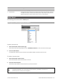
The File Name drop-down list shows the list of file bundles stored in the sensor. The configuration
that is currently loaded is listed at the top. The name will be marked with an asterisk if the live
configuration is different from the loaded configuration to indicate unsaved changes.
To save a new bundle of files:
1.
Select [New] in the File Name drop-down list.
Gocator 2000 & 2300 Series
Gocator Web Interface • User Interface Overview • 50
2.
Enter a name for the file bundle.
3.
Press the Enter key or click the Save button.
The files are saved to flash memory using the name provided. The saved files are set as the defaults to
be loaded automatically when the sensor is reset.
To overwrite an existing bundle of files:
1.
Select an existing file name in the File Name drop-down list.
2.
Click the Save button.
A dialog is displayed to confirm overwriting the existing files. The files are saved to flash memory using
the selected name. The saved files are set as the defaults to be loaded automatically when the sensor
is reset.
To load a bundle of files:
1.
Select an existing file name in the File Name drop-down list.
2.
Click the Load button.
The files are loaded from flash memory, and unsaved changes to current settings are overwritten.
To delete a bundle of files:
1.
Select an existing file name in the File Name drop-down list.
2.
Click the Delete button.
The files are deleted from the flash memory.
Managing individual files is described in Files Panel on page 61.
Managing Multiple Settings
A Gocator can store multiple bundles of configurations, calibrations, and templates. The ability to use
multiple bundles is useful when a Gocator is used for different purposes, or with different constraints
during separate production runs (for example, width decision constraints might be loose during one
production run and tight during another depending on the desired grade of the part).
To manage a system with multiple configurations:
1.
Configure settings for the first target object.
Use the Setup, Measurement, and Output pages to configure settings for the first target.
Gocator 2000 & 2300 Series
Gocator Web Interface • User Interface Overview • 51
2.
Save the first configuration.
Enter a file name and click the Save button to save the configuration.
3.
Configure settings for the second target object.
Use the Setup, Measurement, and Output pages to configure settings for the second target.
4.
Save the second configuration.
Enter a file name (different from the one used for the first configuration) and click the Save button to
save the configuration.
5.
When production changes, load the desired configuration.
Select the desired configuration and click the Load button. The configuration is loaded and the sensors
will ready for production.
Recording, Playback, and Measurement Simulation
Gocator sensors have the ability to record and replay data, and also to simulate measurement tools on
recorded data. This feature is most often used for troubleshooting and fine-tuning measurements, but
can also be helpful during setup.
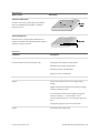
Recording and playback are controlled by using commands in the toolbar.
Recording and Playback commands when Data Source is Live
Recording and Playback commands when Data Source is Replay
To record live data:
1.
Toggle the Data Source to Live.
2.
Press the Record button.
When the Data Source is set to Live and recording is enabled, the sensor will store the most recent
data as it runs. Remember to disable recording if you no longer wish to record live data (press the
Record button again to disable recording).
3.
Press the Snapshot button or Start button.
Gocator 2000 & 2300 Series
Gocator Web Interface • User Interface Overview • 52
Snapshot will cause a single frame to be recorded. The Start button will run the sensor continuously
and all frames will be recorded, up to available memory. When the memory limit is reached, the oldest
data will be discarded. New data is appended to the record buffer unless the configuration has
changed.
Newly recorded data is appended to existing replay data unless the sensor configuration has
been modified.
To replay recorded data:
1.
Toggle the Data Source to Replay.
2.
Use the Replay Slider, Step Forward, Step Back, or Play buttons to review data.
The Step buttons advance / reverse the current replay location by a single frame.
The Play button advances the replay location continuously, animating the playback.
The Pause button (replaces the Play button while playing) can be used to pause the replay at a
particular location.
The Replay slider (or Replay Position box) can be used to navigate to a specific replay frame.
To simulate measurements on recorded data:
1.
Toggle the Data Source to Replay.
2.
Go to the Measurement page.
Modify settings for existing measurements, add new measurement tools, or delete measurement tools
as desired.
3.
Use the Replay Slider, Step Forward, Step Back, or Play button to simulate measurements.
Step or play through recorded data to execute the measurement tools on the recording.
Individual measurement values can be viewed directly in the data viewer. Statistics on measurement
results across the entire recording can be viewed in the Dashboard page; see Dashboard (page 181).
To clear recorded data:
1.
Toggle the Data Source to Replay.
2.
Press the Clear Replay button.
Downloading, Exporting, and Uploading Recorded Data
Recorded data can be downloaded or exported to the client computer, or uploaded to the
Gocator. Export is often used for processing the recorded data using third-party tools. Exported data
can be either range data in CSV format or intensity data in BMP format. Recorded data is downloaded in
a binary format, which is used to back up the data for reviewing in the future.
Gocator 2000 & 2300 Series
Gocator Web Interface • User Interface Overview • 53
Recorded data is not saved or loaded along with other files when you use the Save or Load
commands in the Gocator's toolbar
To download recorded data:
1.
Toggle the Data Source to Replay.
2.
Press the Download button.
3.
Select the directory and file name to download to the client computer. Press OK.
To upload recorded data:
1.
Toggle the Data Source to Live.
2.
Press the Upload button.
3.
Select the directory and the file name to upload from the client computer. Press OK.
To export recorded data to CSV:
1.
Toggle the Data Source to Replay.
2.
Press the Export button.
Select Export Ranges as CSV. In Profile and Raw mode, all data in the record buffer is exported. In Part
mode, only data in the current replay location is exported. Use the Step button to move to a different
replay location; see Recording, Playback, and Measurement Simulation (page 52).
3.
Select the directory and file name to export to the client computer. Press OK.
4.
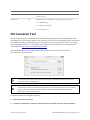
Optionally, convert exported data to another format using the CSV Converter Tool on page
332.
Gocator 2000 & 2300 Series
Gocator Web Interface • User Interface Overview • 54
Recorded intensity data can also be exported to a bitmap (.BMP format):
To export recorded intensity data to BMP:
1.
Toggle the Data Source to Replay.
2.
Press the Export To BMP button.
Select Export Intensity as BMP. Only the intensity data in the current replay location is exported. Use
the Step button to move to a different replay location.
3.
Select the directory and file name to store on the client computer. Press OK.
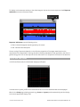
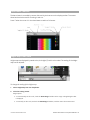
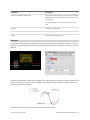
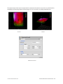
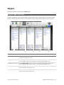
Metrics Panel
The Metrics panel displays two important performance statistics in real-time: CPU load and current
frame rate (speed).
The CPU Load bar in the Metrics panel (at the top of the interface) displays how much of the CPU is
being utilized. A warning symbol will appear if the sensor drops profiles because CPU is over utilized.
The Speed bar displays the frame rate of the sensor. A warning symbol will appear if triggers (external
input or encoder) are dropped because the external rate exceeds the maximum frame rate.
Click on a warning symbol to reveal notifications that display more detailed information.
Gocator 2000 & 2300 Series
Gocator Web Interface • User Interface Overview • 55
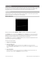
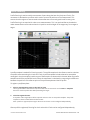
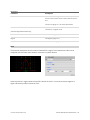
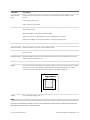
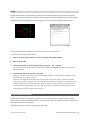
Data Viewer
The data viewer is displayed in both the Setup and the Measurement pages, but displays different
information depending on which page is active.
When the Setup page is active, the data viewer displays sensor data and can be used to adjust regions of
interest. Depending on the selected operation mode (page 67), the data viewer can display video images
or whole part views. For details, see Data Viewer (page 92).
When the Measurement page is active, the data viewer displays sensor data onto which
representations of measurement tools and their measurements are superimposed. For details, see Data
Viewer (page 103).
Gocator 2000 & 2300 Series
Gocator Web Interface • User Interface Overview • 56
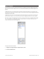
Connection and Maintenance
The following sections describe how to set up the sensor connections and networking, and how to
perform maintenance tasks.
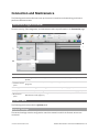
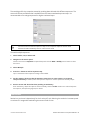
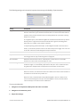
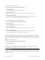
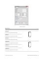
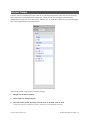
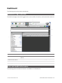
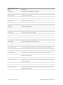
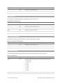
Connection Page Overview
Gocator's security, file management, and maintenance tasks are performed on the Connection page.
Element
1 System panel
Description
Use the System panel to configure sensor network and boot-up settings. See System Panel
(below) .
2 Available Sensors Use the Available Sensors panel to assign or unassign Buddy sensors. See Available Sensors
(page 59) .
panel
3 Security panel
Use the Security panel to change passwords. See Security Panel (page 60) .
4 Files panel
Use the Files panel to manage files stored on the Main sensor. See Files Panel (page 61) .
5 Maintenance
Use the Maintenance panel to upgrade firmware, create/restore backups, or reset sensors. See
panel
Maintenance Panel (page 62) .
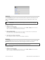
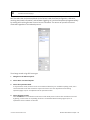
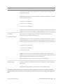
System Panel
The following sections describe the System panel.
Network Settings
The network settings must be configured to match the network to which the Gocator sensors are
connected.
Gocator 2000 & 2300 Series
Gocator Web Interface • Connection and Maintenance • 57
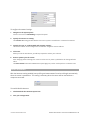
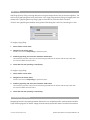
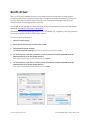
To configure the network settings:
1.
Navigate to the System panel.
Click the arrow next to Networking to expand the panel.
2.
Specify the Connect To setting.
The Connect To setting specifies whether the sensor system is standalone or connected to a Master.
3.
Specify the Type, IP, Subnet Mask, and Gateway settings.
The Gocator sensor can be configured to use DHCP or assigned a static IP address.
4.
Click Save.
When you click the Save button, you will be prompted to confirm your selection.
5.
Reset or power-cycle the sensor.
After changing network settings, the sensor must be reset or power-cycled before the change will take
effect.
The Reset Sensor button in the Maintenance panel (page 62) can be used to perform a software reset.
Sensor Autostart
With the Autostart setting enabled, laser profiling and measurement functions will begin automatically
when the sensor is powered on. This setting is necessary when the sensor will be used without a
computer connected.
To enable/disable Autostart:
1.
Check/Uncheck the Autostart option box.
2.
Save your configuration.
Gocator 2000 & 2300 Series
Gocator Web Interface • Connection and Maintenance • 58
Overheat Temperature Protection
Sensors equipped with a 3B-N laser by default will turn off the laser if the temperature exceeds the safe
operating range. You can override the setting by disabling the overheat protection.
Disabling the setting is not recommended. Disabling the overheat protection feature could lead
to premature laser failure if the sensor operates outside the specified temperature range.
To enable/disable overheat temperature protection:
1.
Check/uncheck the Overheat Protection option box.
2.
Save configuration.
Available Sensors
The following section describes the Available Sensors panel.
Buddy Assignment
In a dual-sensor system, the Main sensor assumes control of the Buddy sensor after the Buddy sensor is
assigned to the Main sensor. Configuration for both sensors can be performed through the Main
sensor's interface.
Main and Buddy sensors must be assigned unique IP addresses before they can be used on the
same network. Before proceeding, connect the Main and Buddy sensors one at a time (to avoid
an address conflict) and use the steps outline in Running a Dual-Sensor System (page 30) to
assign each sensor a unique address.
Gocator 2000 & 2300 Series
Gocator Web Interface • Connection and Maintenance • 59
To assign a Buddy sensor:
1.
Navigate to the Available Sensors panel.
2.
Select a Buddy sensor.
The firmware on Main and Buddy sensors must be the same for Buddy assignment to be successful. If
the firmware is different, connect the Main and Buddy sensor one at a time.
3.
Click Assign.
The Buddy sensor will be assigned to the Main sensor and its status will be updated in the System
panel.
Security Panel
Gocator sensors can be secured with passwords to prevent unauthorized access. Each sensor has two
accounts: Administrator and Technician.
Gocator Account Types
Account
Description
Administrator
The Administrator account has privileges to view and edit all settings, and to perform setup procedures such as sensor calibration.
Technician
The Technician account has privileges to view the Dashboard Page and to Start or Stop the sensor.
The Administrator and Technician accounts can be assigned unique passwords. By default, passwords
are blank (empty).
To set or change the password for the Administrator account:
1.
Navigate to the Security panel.
Click the arrow next to Administrator to expand the panel.
Gocator 2000 & 2300 Series
Gocator Web Interface • Connection and Maintenance • 60
2.
Enter the new Administrator account password and password confirmation.
3.
Click Save.
The new password will be required the next time that an administrator logs in to the sensor.
To set or change the password for the Technician account:
1.
Navigate to the Security panel.
Click the arrow next to Technician to expand the panel.
2.
Enter the new Technician account password and password confirmation.
3.
Click Save.
The new password will be required the next time that a technician logs in to the sensor.
If the administrator or technician password is misplaced, the sensor can be recovered using a special
software tool. See Sensor Recovery Tool (page 324) for more information.
Files Panel
The Files panel can be used to manage configuration, calibration, and template files.
Element
Description
1 File Type
Specifies the type of files to manage (configuration,profile template, or transformation).
2 File Name Field
Used to provide a file name when saving files.
3 File List
Displays the files that are currently saved in the sensor's flash storage.
4 Save Button
Saves currently loaded data to file using the name in the File Name field.
5 Load Button
Loads the file that is selected in the file list.
6 Delete Button
Deletes the file that is selected in the file list.
7 Set as Default Button
Sets the selected file as the default to be loaded at boot time.
8 Download Button
Downloads the selected file to the client computer.
9 Upload Button
Uploads a file from the client computer.
The following types of files can be saved and loaded:
File Types
Gocator 2000 & 2300 Series
Gocator Web Interface • Connection and Maintenance • 61
File Type
Description
Configuration
Contains the settings specified in the Setup , Measurement, and Output pages.
Transformation
Contains settings resulting from calibration.
Profile Template
Contains profile template data used for profile fixturing.
To manage a configuration, calibration, or template file:
1.
Navigate to the Files panel.
2.
Select the file type.
3.
Select the file in the File list.
To save the live configuration, calibration, or template to a file, type in a new file name or select a file to
replace with.
4.
Select the action.
Maintenance Panel
The following sections describe the Maintenance panel.
Sensor Backups and Factory Reset
The Maintenance panel can be used to create sensor backups, restore from a backup, or restore to
factory defaults.
Backup files contain all of the information stored on a sensor, including configuration, calibration, and
template.
An Administrator should create a backup file in the unlikely event that a sensor fails and a
replacement sensor is needed. If this happens, the new sensor can be restored with the backup
file.
To create a backup:
1.
Navigate to the Maintenance panel.
2.
Click the Backup Sensor... button.
Gocator 2000 & 2300 Series
Gocator Web Interface • Connection and Maintenance • 62
3.
When you are prompted, specify a location for the backup.
The backup is saved to the specified location on the client computer. Backups are saved as a single
archive that contains all of the files from the sensor.
To restore from a backup:
1.
Navigate to the Maintenance panel.
2.
Click the Restore Sensor... button.
3.
When you are prompted, select a backup file to restore.
The backup file is uploaded and then used to restore the sensor. Any files that were on the sensor
before the restore operation will be lost.
To restore a sensor to its factory default settings:
1.
Navigate to the Maintenance panel.
2.
Consider making a backup.
Before proceeding, you should perform a backup. Restoring factory defaults cannot be undone.
3.
Click the Restore to Factory button.
4.
Reset the sensor.
After restoring factory defaults, you must reset the sensor before the changes will take effect. Use the
Reset Sensor button or cycle the power to reset the sensor.
Firmware Upgrade
LMI recommends routinely updating firmware to ensure that Gocator sensors always have the latest
features and fixes.
In order for the Main and Buddy sensors to work together, they must be use the same firmware
version. This can be achieved by upgrading through the Main sensor or by upgrading each
sensor individually.
Gocator 2000 & 2300 Series
Gocator Web Interface • Connection and Maintenance • 63
To download the latest firmware:
1.
Click on the Help link.
Make sure that the client computer is connected to the Internet.
2.
Determine if an update is required.
The Help panel will check LMI's website to check if the sensor's firmware is up to date.
3.
Download the latest firmware.
If sensor firmware is not up to date, click the Firmware link to visit LMI's website, and then download
the latest firmware.
If the client computer is not connected to the Internet, firmware can be downloaded and transferred to
the client computer by using another computer to download the firmware from LMI's website:
http://www.lmi3D.com/support/downloads.
To upgrade the firmware:
1.
Navigate to the Maintenance panel.
2.
Click the Update Firmware button.
3.
Provide the location of the firmware file in the File dialog.
4.
Wait for the upgrade to complete.
After the firmware upgrade is complete, the sensor will self-reset. If a buddy has been assigned, it will
be upgraded and reset automatically.
Gocator 2000 & 2300 Series
Gocator Web Interface • Connection and Maintenance • 64
Setup and Calibration
The following sections describe the steps to configure Gocator sensors for laser profiling using the Setup
page. Setup and calibration steps should be performed before programming measurements or outputs.
Calibration in the user interface and in this manual refers to aligning a sensor to system
coordinates.
Setup Page Overview
1
2
Element
Description
Operation Mode
panel
Use the Operation Mode panel to set the current operation mode (Video, Profile, Part, or
Raw) and other options. See Operation Mode Panel (page 67) .
Trigger panel
Use the Trigger panel to specify the trigger source and trigger-related settings. See Trigger
Panel (page 67) .
3
Sensor panel
Use the Sensor panel to specify settings for an individual sensor, such as active area or
exposure. See Sensor Panel (page 72) .
4
Layout panel
Use the Layout panel to configure a dual-sensor (Main/Buddy) system and to perform
Gocator 2000 & 2300 Series
Gocator Web Interface • Setup and Calibration • 65
Element
Description
alignment or travel calibration. See Layout Panel (page 82) .
5
Filters panel
Use the Filters panel to specify settings for post-processing of the profiles. See Filters Panel
(page 88) .
6
Detection panel
Use the Detection panel to set the part detection logic for sorting profiles into discrete
objects. See Detection Panel (page 90) .
7
Data Viewer
Use the data viewer to display sensor data and adjust regions of interest. Depending on the
current operation mode, the data viewer can display video images , profile plots, or part
views . See Data Viewer (page 92) .
The following table provides quick references for specific goals that you can achieve from the panels in
the Setup page.
Goal
Reference
1
Select a trigger source that is appropriate for the application.
Trigger
Panel
(next
page)
2
Ensure that camera exposure is appropriate for laser profiling .
Exposure
(page 75)
3
Find the right balance between profile quality, speed, and CPU utilization.
Active
Area
(page 72)
Exposure
(page 75)
Gocator
Device
Files
(page
184)
4
Specify mounting orientations for dual-sensor systems.
DualSensor
System
Layout
(page 82)
5
Calibrate the system so that laser profile data can be aligned to a common reference and values can
Alignment
Calibratio
n (page
85)
be correctly scaled in the axis of motion.
Travel
Calibratio
n (page
Gocator 2000 & 2300 Series
Gocator Web Interface • Setup and Calibration • 66
Goal
Reference
293)
6
Specify smoothing, gap-filling, and resampling parameters to remove effects of occlusions.
Filters
Panel
(page 88)
7
Set up the part detection logic to sort profiles into discrete objects.
Detection
Panel
(page 90)
Operation Mode Panel
The Gocator web interface supports four operation modes: Video, Profile, Raw, and Whole Part. The
operation mode can be selected in the Operation Mode panel.
Mode and Option
Description
Video
Outputs video images from the Gocator. This mode is useful for configuring exposure
time and troubleshooting stray light or ambient light problems.
Profile
Outputs profiles and performs profile measurements. Video images are processed
internally to produce laser profiles and cross-sectional measurements.
Raw
Outputs profiles. In Raw Mode, video images are processed internally by the sensor to
produce laser profiles. Use this mode to extract unprocessed ranges from the Gocator
at the highest possible rate. Post-profiling processing and measurements are disabled.
Acquire Intensity
When this option is enabled, an intensity value will be produced for each laser profile
point.
Trigger Panel
A trigger is an event that causes a sensor to take a single picture. When a trigger is processed, the laser is
strobed and the camera exposes to produce an image. The resulting image is processed inside the sensor
to yield a profile (range/distance information), which can then be used for measurement.
The laser and camera inside a sensor can be triggered by one of the following sources:
Trigger Source
Description
Time
Sensors have an internal clock that can be used to generate fixed-frequency triggers.
The external input can be used to enable or disable the time triggers.
Gocator 2000 & 2300 Series
Gocator Web Interface • Setup and Calibration • 67
Trigger Source
Description
Encoder
An encoder can be connected to provide triggers in response to motion. Three encoder
triggering behaviors are supported:
1. Ignore Backward
A scan is triggered when the target object moves forward. If the target object moves
backward, it must move forward by at least the distance that the target travelled
backward, plus one encoder spacing, to trigger a scan.
2. Track Backward
A scan is triggered only when the target object moves forward. If the target object
moves backward, it must move forward by at least the distance of one encoder spacing
to trigger a scan.
3. Bi-directional
A scan is triggered when the target object moves forward or backward.
Gocator 2000 & 2300 Series
Gocator Web Interface • Setup and Calibration • 68
Trigger Source
Description
When triggers are received at a frequency higher than the maximum frame rate, some
triggers may not be accepted. The Trigger Drops Indicator in the Dashboard can be used
to check for this condition.
The external input can be used to enable or disable the encoder triggers.
See Encoder Input on pages 363 and 370 for more information on connecting the
encoder to Gocator sensors.
External Input
A digital input can provide triggers in response to external events (e.g., photocell).
When triggers are received at a frequency higher than the maximum frame rate, some
triggers may not be accepted. The Trigger Drops Indicator in the Dashboard can be used
to check for this condition.
See Digital Inputs on pages 362 and 370 for more information on connecting external
input to Gocator sensors.
Software
A network command can be used to send a software trigger. See Protocols (page 266)
for more information.
For examples of typical real-world scenarios, see next page. For information on the settings used with
each trigger source, see page 71
Gocator 2000 & 2300 Series
Gocator Web Interface • Setup and Calibration • 69
Trigger Examples
Example: Encoder + Conveyor
Encoder triggering is used to perform profile
measurements at a uniform spacing.
The speed of the conveyor can vary while the
object is being measured; an encoder ensures
that the measurement spacing is consistent,
independent of conveyor speed.
Example: Time + Conveyor
Time triggering can be used instead of encoder
triggering to perform profile measurements at a
fixed frequency.
Measurement spacing will be non-uniform if the
speed of the conveyor varies while the object is
being measured.
It is strongly recommended to use an encoder
with transport-based systems due to the
difficulty in maintaining constant transport
velocity.
Example: External Input + Conveyor
External Input triggering can be used to
produce a snapshot for profile measurement.
For example, a photocell can be connected as
an External Input to generate a trigger pulse
when a target object has moved into position.
An External Input can also be used to gate the
trigger signals when Time or Encoder triggering
is used. For example, a photocell could generate
a series of trigger pulses as long as there is a
target in position.
Gocator 2000 & 2300 Series
Gocator Web Interface • Setup and Calibration • 70
Example: Software Trigger + Robot Arm
Software triggering can be used to produce a
snapshot for profile measurement.
A software trigger can be used in systems that
use external software to control the activities of
system components.
Trigger Settings
The trigger source is selected using the Trigger panel in the Setup page.
After specifying a trigger source, the Trigger panel will show the parameters that can be configured. Parameter
Trigger Source
Description
Trigger
All
Selects the trigger source (Time, Encoder, External Input, or Software).
Max Frame Rate All
Reports the maximum frame rate, which is a function of the current Active
Area, Exposure, and Resolution settings.
Frame Rate
Time
The Frame Rate setting can be used to control the frame rate. Select the Max
check box to lock to the maximum frame rate. Fractional values are supported.
For example, 0.1 can be entered to run at 1 frame every 10 seconds.
Gocator 2000 & 2300 Series
Gocator Web Interface • Setup and Calibration • 71
Parameter
Trigger Source
Description
Gate using
Time, Encoder
External input can be used to enable or disable profiling in a sensor. When this
External Input
option is enabled, the sensor will respond to time or encoder triggers only
when the external input is asserted.
See Digital Inputs on pages 362 and 370 for more information on connecting
external input to Gocator sensors.
Travel Speed
Time
Travel Speed provides proper scaling in the Y axis (axis of motion). Travel Speed
can be calculated automatically by performing Travel Calibration or set manually after clicking on the unlock button.
Encoder Beha-
Encoder
vior
Encoder Res-
Encoder Behavior setting is used to specify how the Gocator sensor is triggered
when the target moves.
Encoder
olution
Encoder Resolution (millimeters per tick) provides proper scaling in the Y axis
(axis of motion). The encoder resolution can be calculated automatically by performing Travel Calibration or set manually after clicking on the unlock button.
Spacing
Encoder
Encoder Spacing setting is used to specify the distance between triggers (mm).
Internally the Gocator sensor rounds the spacing to a multiple of the encoder
resolution.
Units
External Input,
Units specifies whether the trigger delay, output delay and output scheduled
Software
command operates in the time or the encoder domain. The unit is implicitly set
to microseconds with Time trigger source, and millimeters with Encoder trigger
source.
Trigger Delay
External Input
Trigger delay can be used to control the amount of time or the distance the
sensor waits before producing a frame after the external input is activated. This
is used to compensate for the positional difference between the source of the
external input trigger (e.g., photocells) and the sensor.
Trigger delay is only supported in single exposure mode; for details, see
Exposure (page 75) .
Sensor Panel
The following sections describe the Sensor panel.
Active Area
Active area refers to the region within the sensor's maximum field of view that is used for laser profiling .
By default, the active area covers the sensor's entire field of view. By reducing the active area, the sensor
can operate at higher speeds.
Gocator 2000 & 2300 Series
Gocator Web Interface • Setup and Calibration • 72
Active area is specified in sensor coordinates,
rather than in system coordinates. As a result, if
the sensor is already alignment calibrated, press
the Acquire button to display uncalibrated data
before configuring the active area. See Coordinate
Systems (page 45) for more information on sensor
and system coordinates.
To set the active area:
1.
Navigate to the Sensor panel.
Active area is specified separately for each sensor. Click the arrow next to Active Area to expand the
panel.
2.
Click the Select button.
3.
Define the active area.
Enter the active area in the edit box or adjust it graphically in the data viewer.
The 2D view allows you to adjust the sizes and positions in the X axis and Z axis. The 3D view allows you
to adjust the sizes and positions in the X axis, Y axis, and Z axis. See Regions (page 107) for details.
4.
Click the Acquire button to see a scan while setting up the active area.
5.
Click the Save button.
Gocator 2000 & 2300 Series
Gocator Web Interface • Setup and Calibration • 73
Laser profiling devices are usually more accurate at the near end of their measurement range.
If your application requires a measurement range that is small compared to the maximum
measurement range of the sensor, mount the sensor so that the active area can be defined at
the near end of the measurement range.
Tracking Window
The Gocator can track a relatively flat object in real-time to achieve very high scan rates. This feature
tracks the object height using a small window that moves dynamically to cover a larger measurement
range. You can balance the gain in speed and the tracking ability by configuring the size of the tracking
area. This feature is typically used in road or web scanning applications where the target is a continuous
flat surface.
A laser line remains tracked as long as the percentage of detected laser points exceeds the user-defined
search threshold. When the sensor loses track of the laser line, the sensor will search for the laser line
using the full active area.
Tracking window is only supported on the Gocator 2300 series.
Gocator 2000 & 2300 Series
Gocator Web Interface • Setup and Calibration • 74
To enable the tracking window:
1.
Check the Tracking Window box.
Checking the Tracking Window box expands the panel and shows the settings for the window used to
track the object height.
2.
Resize the tracking window shown in the data viewer.
Only the height of the window is required. You can move the position of the tracking window to cover a
live profile to help adjust the window height.
3.
Edit the Search Threshold setting.
The search threshold defines the minimum percentage of the points detected across the profile for the
laser to be considered tracked. If tracking is lost, the sensor will search for the laser using the full active
area.
The sensor adjusts the position of the tracking window so that the area is centered around the average
height of the entire visible laser profile. You should adjust the lighting and the active area to remove all
background objects, such as the conveyor belt surface, ambient lights, etc.
Exposure
Exposure determines the duration of camera and laser on-time. Longer exposures can be helpful to
detect laser signals on dark or distant surfaces, but increasing exposure time decreases the maximum
speed. Different target surfaces may require different exposures for optimal results. Gocator sensors
provide three exposure modes for the flexibility needed to scan different types of target surfaces.
Exposure Mode
Description
Single
Uses a single exposure for all objects. Used when the surface is uniform and is the same for
all targets.
Dynamic
Automatically adjusts the exposure after each frame. Used when the target surface varies
between scans.
Multiple
Uses multiple exposures to create a single profile. Used when the target surface has a varying
reflectance within a single profile (e.g., white and black).
Video mode lets you see how the laser line appears on the camera and identify any stray light or
ambient light problems. When exposure is tuned correctly, the laser should be clearly visible along the
entire length of the viewer. If it is too dim, increase the exposure value; if it is too bright decrease
exposure value.
Gocator 2000 & 2300 Series
Gocator Web Interface • Setup and Calibration • 75
Under exposure
Over exposure
Laser line is not detected.
Laser line is too bright .
Increase the exposure value.
Increase the exposure value.
In a dual-sensor system, the Main and the Buddy sensor must use the same exposure mode or
the system will fail to start.
When the Gocator is in Multiple exposure mode, select which exposure to view using the drop-down box
next to "View" in the data viewer. This drop-down is only visible in Video operation mode when the
Multiple option is selected in the Exposure section in the Sensor panel.
Single Exposure
The sensor uses a fixed exposure in every scan. Single exposure is used when the target surface is
uniform and is the same for all parts.
Gocator 2000 & 2300 Series
Gocator Web Interface • Setup and Calibration • 76
To enable single exposure:
1.
Place a representative target in view of the sensor.
The target surface should be similar to the material that will normally be measured.
2.
Select Profile, Part, or Raw mode.
3.
Navigate to the Sensor panel.
Click the arrow next to Exposure to expand the panel. Click the Main or Buddy sensor button to select
the sensor.
4.
Select Single.
5.
Edit the Exposure setting.
You can automatically tune the exposure by pressing the Auto Set button, which causes the sensor to
turn on and tune the exposure time.
6.
Run the sensor and check that laser profiling is satisfactory.
If not satisfactory, adjust the exposure values manually. Switch to Video mode to use video to help tune
the exposure; see Exposure (page 75) for details.
Dynamic Exposure
The sensor automatically uses past profile information to adjust the exposure to yield the best profile.
This is used when the target surface changes from scan to scan.
Gocator 2000 & 2300 Series
Gocator Web Interface • Setup and Calibration • 77
To enable dynamic exposure:
1.
Select Profile, Part, or Raw mode.
2.
Navigate to the Sensor panel.
Click the arrow next to Exposure to expand the panel. Click the Main or Buddy sensor button to select
the sensor.
3.
Select Dynamic.
4.
Set the minimum and maximum exposure.
The auto-set function can be used to automatically set the exposure. First, place the brightest target in
the field of view and press the Auto Set Min button to set the minimum exposure. Then, place the
darkest target in the field of view and press the Auto Set Max button to set the maximum exposure.
5.
Run the sensor and check that laser profiling is satisfactory.
If not satisfactory, adjust the exposure values manually. Switch to Video mode to use video to help tune
the exposure; see Exposure (page 75) for details.
Multiple Exposures
The sensor combines data from multiple exposures to create a single laser profile . Multiple exposures
can be used to increase the ability to detect light and dark materials that are in the field of view
simultaneously.
Up to five exposures can be defined with each set to a different exposure level. For each exposure, the
sensor will perform a complete scan at the current frame rate making the effective frame rate slower.
For example, if two exposures are selected, then the speed will be half of the single exposure frame rate.
The sensor will perform a complete multi-exposure scan for each external input or encoder trigger.
Gocator 2000 & 2300 Series
Gocator Web Interface • Setup and Calibration • 78
The resulting profile is a composite created by combing data collected with different exposures. The
sensor will choose profile data that is available from the lowest-numbered exposure step. It is
recommended to use a larger exposure for higher-numbered steps.
You must make sure that the exposure steps set for composite exposure are the same
between the Main and Buddy sensors in dual-sensor mode
To enable multiple exposures:
1.
Select Profile, Part, or Raw mode.
2.
Navigate to the Sensor panel.
Click the arrow next to Exposure to expand the panel. Click the Main or Buddy sensor button to select
the sensor.
3.
Select Multiple.
4.
Press the + button to add an exposure step.
Up to a maximum of five exposure settings can be added.
5.
Set the exposure level to make the Gocator's camera less or more sensitive, as required.
If Acquire Intensity is enabled, select the exposure step that is used to capture the intensity output.
6.
Run the sensor and check that laser profiling is satisfactory.
If not satisfactory, adjust the exposure values manually. Switch to Video mode to use video to help tune
the exposure; see Exposure (page 75) for details.
Resolutions
Resolutions can be set independently for the X axis and Z axis. Reducing the resolution increases speed
or reduces CPU usage while maintaining the sensor's field of view.
Gocator 2000 & 2300 Series
Gocator Web Interface • Setup and Calibration • 79
X Resolution
The X Resolution setting can be used to decrease the profile's X resolution to decrease sensor CPU
usage. The X Resolution setting works by reducing the number of image columns used for laser
profiling.
The CPU Load bar at the top of the interface displays how much of the CPU is being used.
To configure X resolution:
1.
Navigate to the Sensor panel.
Click the arrow next to Resolution to expand the panel. Click the Main or Buddy button to select the
sensor. X resolution is specified separately for each sensor.
2.
Select a resolution value.
X resolution values are expressed as fractions. For example, a resolution value of 1/2 indicates that
every second camera column will be used for laser profiling.
3.
Check that laser profiling is satisfactory.
After adjusting the resolution, confirm that laser profiling is satisfactory.
Z Resolution
The Z Resolution setting can be used to decrease the profile's Z resolution to increase speed. The Z
Resolution setting works by reducing the number of image rows used for laser profiling.
On the Gocator 2000, decreasing the Z resolution will increase speed. On the Gocator 2300,
both the X and the Z resolutions must be decreased to increase speed.
To configure Z resolution:
1.
Navigate to the Sensor panel.
Click the arrow next to Resolution to expand the panel. Click the Main or Buddy button to select the
sensor. Z resolution is specified separately for each sensor.
Gocator 2000 & 2300 Series
Gocator Web Interface • Setup and Calibration • 80
2.
Select a resolution value.
Z resolution values are expressed as fractions. For example, a resolution value of 1/2 indicates that
every second camera row will be used for laser profiling.
3.
Check that laser profiling is satisfactory.
Decreasing Z resolution can reduce laser profiling accuracy. After adjusting the resolution, confirm that
laser profiling is satisfactory.
Transformations
The transformation settings are used to control how profiles are converted from sensor coordinates to
system coordinates.
The system coordinate transformation is normally set through the Gocator's automatic
calibration procedure and are locked by default; see Calibration (page 83). However, if you
need to manually adjust the transformation, the settings are available in this section.
Element
Description
X Offset
Specifies the shift along the X axis. With Normal orientation, a positive value shifts the profiles to
the right. With Reverse orientation, a positive value shifts the profile to the left.
Z Offset
Specifies the shift along the Z axis. A positive value shifts the profiles toward the sensor.
Angle
Specifies the tilt (rotation in the X-Z plane). A positive value rotates the profile counter-clockwise.
Orientation
Specifies the direction of the X axis. Setting to Reverse will flip the profile about the Z axis.
When applying the transformations, Angle is applied before the X and Z offsets.
To configure transformation settings:
1.
Select Profile, Part, or Raw mode.
2.
Navigate to the Sensor panel.
Click the arrow next to Transformation to expand the panel. Click the Main or Buddy button to select
the sensor. Transformations can be configured separately for each sensor.
Gocator 2000 & 2300 Series
Gocator Web Interface • Setup and Calibration • 81
3.
Click the unlock button to make the fields editable.
4.
Set the parameter values.
5.
Check that the transformation settings are applied correctly after profiling is restarted.
Layout Panel
The following sections describe the Layout panel.
Dual-Sensor System Layout
Mounting orientations must be specified for a dual-sensor system. This information allows the
Alignment or Travel Calibration procedures to determine the correct system-wide coordinates for laser
profiling and measurements. See Coordinate Systems (page 45) for more information on sensor and
system coordinates.
To specify the layout, navigate to the Layout panel on the Setup page:
Supported Orientations
Orientation
Example
None (Isolated)
Each sensor operates as an isolated device.
Measurements are reported in a separate
coordinate system for each sensor.
Wide
Sensors are mounted in Left (Main) and Right
(Buddy) positions for a larger combined field of
view. Sensors may be angled to avoid
occlusions.
Gocator 2000 & 2300 Series
Gocator Web Interface • Setup and Calibration • 82
Orientation
Example
Opposite
Sensors are mounted in Top (Main) and Bottom
(Buddy) positions for a larger combined
measurement range and the ability to perform
Top/Bottom differential measurements.
Overlap
If the Main and Buddy sensors are mounted such that the camera from one sensor can detect the laser
from the other sensor, the Overlap option can be used to eliminate laser interference. This option
creates a time offset for laser exposures and ensures that interfering lasers are not strobed at the same
time. Use of the Overlap option may reduce the maximum frame rate.
Reverse
In Wide orientation (see page 59 for information on orientations), the Buddy sensor can be mounted
such that it is rotated 180 degrees around the Z axis to prevent occlusion along the Y axis. Enable the
Reverse option when the buddy is mounted in this orientation.
Calibration
Although Gocator sensors are pre-calibrated and ready to deliver profiles in engineering units (mm) out
of the box, calibration procedures are required to compensate for sensor mounting inaccuracies, to align
multiple sensors into a common coordinate system, and to determine the resolution (with encoder) and
speed of the transport system.
Gocator sensors support two types of calibration procedures: alignment calibration and travel
calibration. Travel calibration performs essentially the same role as alignment calibration, but calibrates
encoder resolution and Y axis offsets in addition to the corrections provided by alignment calibration.
Once calibration has been completed, the derived transformation values will be displayed under
Transformations in the Sensor panel; see Transformations (page 81) for details.
Gocator 2000 & 2300 Series
Gocator Web Interface • Setup and Calibration • 83
Calibration States
A Gocator can be in one of three calibration states: None, Manual, or Auto.
Calibration State
State
Explanation
None
Sensor has no calibration. Profiles are reported in default sensor coordinates.
Manual
Transformations or encoder resolution have been manually edited.
Auto
Sensor is calibrated using either alignment or travel calibration.
An indicator on the Calibration panel will display CALIBRATED, MANUALLY CALIBRATED, or NOT
CALIBRATED, depending on the Gocator's state.
Transformation Sources
Gocator sensors support two types of transformation sources: Global or Current Configuration. The
choice for the transformation source depends on how the sensor will be used.
You can switch between transformation sources at any time.
Source
Description
Global transformation
A single global transformation is applied to the profile that is acquired, regardless
of what configuration is currently loaded on the sensor.
The global transformation is saved on the sensor in a separate hidden file and is
retained when the sensor is reset or powered off.
Global transformation is typically used when the sensor mounting is constant
over time and between scans, e.g., when the sensor is mounted in a permanent
position over a conveyor belt.
Current Configuration
The transformation is associated with a specific configuration.
The transformation is saved with the same file name as the current configuration
(but with a different extension). The transformation is accessible through the file
manager; see Files Panel (page 61) for details. When a configuration is loaded on
the sensor, the associated transformation is automatically loaded together with it.
Current Configuration is typically used when the sensor's position relative to
the object scanned is always changing, e.g., when the sensor is mounted on a
robot arm moving to different scanning locations.
Gocator 2000 & 2300 Series
Gocator Web Interface • Setup and Calibration • 84
Alignment vs. Travel Calibration
The table below summarizes the differences between alignment calibration and travel calibration.
Alignment Calibration vs. Travel Calibration
Alignment Calibration
Travel Calibration
Flat surface or calibration bar
Calibration disk or calibration bar
Stationary
Linear motion
Calibrates Tilt
Yes
Yes
Calibrates Z axis Offset
Yes
Yes
Calibrates X axis Offset
Yes (Calibration bar required)
Yes
Calibrates Encoder
No
Yes
Calibrates Travel Speed
No
Yes
Target Type
Target/Sensor Motion
See Coordinate Systems (page 45) for definitions of coordinate axes. See Calibration Targets (page 26) for
descriptions of calibration disks and bars.
The procedures to perform alignment calibration or travel calibration are described in the next sections.
After calibration, the coordinate system for laser profiles will change from sensor coordinates to system
coordinates.
Alignment Calibration
Alignment calibration can be used to compensate for mounting inaccuracies by aligning sensor data to a
common reference surface (often a conveyor belt).
To perform alignment calibration:
1.
Ensure that all sensors have a clear view of the target surface.
Remove any irregular objects from the sensor's field of view that might interfere with alignment
calibration. If using a calibration bar for a dual-sensor system, ensure that the lasers illuminate a
reference hole on the calibration bar.
2.
Navigate to the Layout panel and select Global or Current Configuration as the Source.
Click the arrow button next to Calibration to expand the panel. See Transformation Sources (previous
page) for details on transformation sources.
Gocator 2000 & 2300 Series
Gocator Web Interface • Setup and Calibration • 85
3.
Select Alignment Calibration as the Type.
4.
Clear the previous calibration if present.
Press the Clear Calibration button to remove an existing calibration.
5.
Select a calibration Target.
Select Flat Surface to use the conveyor surface (or other flat surface) as the calibration reference, or
Bar to use a custom calibration bar. If using a calibration bar, specify the bar dimensions and reference
hole layout. See Calibration Targets (page 26) for details.
6.
Place the target under the sensor
7.
Press the Calibrate button.
The sensors will start, and the alignment calibration process will take place. Calibration is performed
simultaneously for all sensors. If the sensors do not calibrate, check and adjust the exposure settings.
Alignment calibration uses the exposure defined for the single exposure mode,
regardless of the current exposure mode
8.
Use Profile mode to inspect calibration results.
Laser profiles from all sensors should now be aligned to the calibration target surface. The base of the
calibration target (or target surface) provides the origin for the system Z axis.
Alignment calibration does not automatically calibrate the resolution of the encoder (if present)
or the travel speed. However, these values can be manually entered if desired. See Trigger
Panel (page 67) for more information.
When using a calibration bar, there can be at most one hole in each sensor's field of view.
Travel Calibration
Travel calibration can be used to achieve alignment calibration and motion calibration in a single
procedure.
Gocator 2000 & 2300 Series
Gocator Web Interface • Setup and Calibration • 86
To perform travel calibration:
1.
Place the calibration target before the laser plane.
Remove other objects from the transport system so that the calibration target is the only object that is
scanned.
2.
Navigate to the Layout panel and select Global or Current Configuration as the Source.
Click the arrow button next to Calibration to expand the panel.
3.
Select Travel Calibration as the Type.
4.
Select a calibration Target.
Select one of the Disk options to use a standard disk target or Bar to use a custom-made calibration
bar. If using a calibration bar, specify the bar dimensions and reference hole layout. See Calibration
Targets (page 26) for details.
5.
Press the Calibrate button.
The sensors will start and then wait for the calibration target to pass through the laser plane.
Travel calibration uses the exposure defined for single exposure mode, regardless of
the current exposure mode.
6.
Engage the transport system.
When the calibration target has passed completely through the laser plane, the calibration process will
complete automatically. To properly calibrate the travel speed, the transport system must be running
at the production operating speed before the target passes through the laser plane.
7.
Use Profile mode to inspect calibration results.
Laser profiles from all sensors should now be aligned to the calibration target surface. The base of the
calibration target (or target surface) provides the origin for the system Z axis.
When using a calibration bar, there can be at most one hole in each sensor's field of view.
If a disk is used for calibrating a dual-sensor setup in a wide layout, half of the disk must be
in each sensor's field of view.
Clearing Calibration
To clear calibration:
1.
Navigate to the Calibration panel on the Setup page.
2.
Select whether to clear the Global or the Current Configuration transformation source.
3.
Click the Calibration or Clear Calibration button.
If the Clear Calibration button is pressed, the calibration will be erased and sensors will revert to using
sensor coordinates.
Gocator 2000 & 2300 Series
Gocator Web Interface • Setup and Calibration • 87
Filters Panel
The Filters panel can be used to post-process a profile before it is output or is used by measurement
tools.
The following types of filters are supported:
Filter
Description
X Resampling Interval
Configures resampling interval size to balance between CPU loading, output data rate,
and X resolution.
Smoothing
Applies moving window averaging to reduce random noise in a profile.
Gap Filling
Fills in missing data caused by occlusions using information from the nearest neighbors.
Smoothing
Smoothing works by substituting a profile result with the average value of itself and its nearest
neighbors. Smoothing can be applied along the X axis or the Y axis. X smoothing works by calculating a
moving average across samples within the same profile. Y smoothing works by calculating a moving
average in the direction of travel at each X location.
If both X and Y smoothing are enabled, the data is smoothed along X axis first, then along the Y axis.
To configure X smoothing:
1.
Select Profile or Part mode.
2.
Navigate to the Filters panel.
Click the arrow next to Smoothing to expand the panel.
3.
Enable X Smoothing and select the window value.
The window value represents the averaging window size along the X axis.
4.
Check that the laser profiling is satisfactory.
To configure Y smoothing:
1.
Select Profile or Part mode.
2.
Navigate to the Filters panel.
Click the arrow next to Smoothing to expand the panel.
3.
Enable Y Smoothing and select the window value.
The window value represents the averaging window size along the Y axis.
4.
Check that the laser profiling is satisfactory.
Gocator 2000 & 2300 Series
Gocator Web Interface • Setup and Calibration • 88
Gap Filling
Gap filling works by filling in missing data points using the lowest values from the nearest neighbors. The
sensor can fill gaps along both the X axis and the Y axis. X gap filling works by filling in the gaps within the
same profile. Y gap filling works by filling in gaps in the direction of travel at each X location.
If both X and Y gap filling are enabled, missing data is filled along the X axis first, then along the Y axis.
To configure X gap filling:
1.
Select Profile or Part mode.
2.
Navigate to the Filters panel.
Click the arrow next to Gap Filling to expand the panel.
3.
Enable X gap filling and select the maximum width value.
The maximum gap value represents the maximum gap width that the Gocator will fill. Gaps wider than
the maximum width will not be filled.
4.
Check that the laser profiling is satisfactory.
To configure Y gap filling::
1.
Select Profile or Part mode.
2.
Navigate to the Filters panel.
Click the arrow next to Gap Filling to expand the panel.
3.
Enable Y gap filling and select the maximum width value.
The maximum gap value represents the maximum gap width that the Gocator will fill. Gaps wider than
the maximum width will not be filled.
4.
Check that the laser profiling is satisfactory.
X Resampling Interval
Resampling interval is the spacing between data points in a resampled profile; see Resampled and Raw
Profile Format (page 46) for details. A larger interval creates profiles with lower X resolution but reduces
Gocator 2000 & 2300 Series
Gocator Web Interface • Setup and Calibration • 89
CPU usage and potentially increases the maximum frame rate. A larger interval also reduces the data
output rate.
By default, the Gocator outputs data at the medium resolution.
To configure the X resampling interval:
1.
Select Profile or Part mode.
2.
Navigate to the Filter panel.
Click the arrow next to X Resampling to expand the panel.
3.
Select a resampling interval level.
Maximum Speed: Use the lowest X resolution within the active area as the resampling interval. This
setting minimizes CPU usage and data output rate but the profile has the lowest X resolution (i.e., least
detail).
Balanced: Use the X resolution at the middle of the active area as the resampling interval. This setting
balances CPU load, data output rate and the X resolution.
Maximum Resolution: Use the highest X resolution within the active area as the resampling interval.
This setting maximizes resolution but has higher CPU load and has the highest data output rate (i.e.,
greatest detail).
Detection Panel
In Part mode, the Gocator sensor analyzes each profile to identify discrete objects. Part measurements
can then be performed on each discrete object.
Part detection can be performed when the trigger source is set to Time or Encoder. To use the Time
trigger source, the travel speed must be calibrated. To use the Encoder trigger source, the encoder
resolution must be calibrated. See Travel Calibration (page 86) for more information.
Multiple parts can pass through the laser at the same time and will be individually tracked. Parts can be
separated along the laser line (X axis), in the direction of travel (Y axis), or by gated external input.
Gocator 2000 & 2300 Series
Gocator Web Interface • Setup and Calibration • 90
The following settings can be tuned to improve the accuracy and reliability of part detection.
Setting
Description
Height Threshold
Determines the profile height threshold for part detection. The setting for Threshold
Direction determines if parts should be detected above or below the threshold. Above is
typically used to prevent the belt surface from being detected as a part when scanning
objects on a conveyor.
In an opposite layout, the threshold is applied to the difference between the top and the
bottom profile. Target thinner than the threshold value is ignored, including places
where only one of either top or bottom is detected.
To separate part by gated external input, set the Height Threshold to the Active area Z
offset (i.e., minimum Z position of the current Active Area), set the trigger source to Time
or Encoder and check the Gate Using External Input check box.
Threshold Direction
Determines if parts should be detected above or below the Height Threshold.
Gap Threshold
Determines the minimum separation between objects in the XY plane. If parts are closer
than the gap interval, they will be merged into a single part.
Area Threshold
Determines the minimum area for a detected part. Set this value to a reasonable
minimum in order to filter out small objects or noise.
Maximum Length
Determines the maximum length of the part object. When the object exceeds the
maximum length, it is automatically separated into two parts. This is useful to break a
long object into multiple sections and perform measurements on each section.
Frame of Reference
Determines the coordinate reference for part measurements.
When set to Sensor, all measurement values are relative to the sensor's Field of View in X
and relative to the encoder zero position in Y.
When set to Part, all measurements except Bounding Box X and Y are relative to the
center of the bounding box of the part. For Bounding Box X and Y, the measurement
values are always in the Sensor Frame of Reference.
To set up part detection:
1.
Navigate to the Operation Mode panel and select Part mode.
2.
Navigate to the Detection panel.
3.
Adjust the settings.
Gocator 2000 & 2300 Series
Gocator Web Interface • Setup and Calibration • 91
Data Viewer
The data viewer can display video images, profile plots, height maps, and intensity images. It is also used
to configure the active area (see page 72) and measurement tools (see page 100). The data viewer
changes depending on the current operation mode and the panel that has been selected.
Video Mode
In Video operation mode, the data viewer displays a camera image. In a dual-sensor system, camera
images from the Main or the Buddy sensor can be displayed.
Exposure Mode View
Exposure can be set to either Multiple or Single. For details on setting exposure, see page 75.
If the Multiple option is selected in the Exposure field in the Sensor panel, a second drop-down is
displayed at the top of the data viewer. This drop-down lists the exposures that have been added.
Choosing an exposure changes the view of the data viewer to that exposure.
If the Single option is selected in the Exposure field's section, the exposure drop-down will not be
shown and only one exposure will be displayed.
To select the view of the display:
1.
Navigate to the Setup page.
2.
Select the camera view.
Select Main or Buddy from the first drop-down list next to View at the top of the data viewer.
Select Front Camera or Back Camera from the first drop-down list next to View at the top of the data
viewer.
3.
Select the exposure.
Select the exposure from the second drop-down list next to View at the top of the data viewer. This
drop-down is only be visible if the Multiple option has been selected.
Gocator 2000 & 2300 Series
Gocator Web Interface • Setup and Calibration • 92
To display a color exposure overlay on the video image to help set the correct exposure, check Exposure
Indication at the top of the data viewer.
Exposure Indication uses the following colors:
n
Blue: Indicates background pixels ignored by the sensor.
n
Red: Indicates saturated pixels.
Correct tuning of exposure depends on the reflective properties of the target material and on the
requirements of the application. Settings should be carefully evaluated for each application, but often a
good starting point is to set the exposure so that there are 2 to 3 red pixels in the center of the laser line.
Profile and Raw Mode
In Profile and Raw mode, the data viewer displays profile plots.
In a dual-sensor system, profiles from individual sensors or from a combined view can be displayed.
When in the Setup page, selecting a panel (e.g., Sensor or Layout panel) automatically sets the display
to the most appropriate display view.
Gocator 2000 & 2300 Series
Gocator Web Interface • Setup and Calibration • 93
To manually select the display view in the Setup Page:
1.
Navigate to the Setup page.
2.
Select the view.
The view of an individual sensor or the combined view of two sensors can be selected from the dropdown list at the top of the data viewer.
In the Measurement page, the view of the display is set to the profile source of the selected
measurement tool.
Whole Part Mode
In Whole Part operation mode, the data viewer can display height maps and intensity images of the
detected objects. You can select the data to display from the View option.
Clicking on the 3D button displays Whole Part data in the 3D viewer. The 3D model is overlaid with the
information that corresponds to the selected View option.
View Option
Information
Profile
Profile Plots the last collected profile. (Only available in 2D view.)
Heightmap
In 2D view, displays the pseudo color height map.
In 3D view, overlays the 2D pseudo color height map on the 3D model.
Uniform
Overlays a uniform shaded surface on the 3D model. (Only available in 3D view.)
Intensity
In 2D view, displays the intensity.
In 3D view, overlays the intensity map on the 3D model.
(Acquire Intensity must be checked in the Operation Mode panel.)
Gocator 2000 & 2300 Series
Gocator Web Interface • Setup and Calibration • 94
Choosing the Profile view option will switch the data viewer out of the 3D viewer and display the profile
plot.
2D viewer for height map
2D viewer for intensity
3D viewer with height map overlay
3D viewer with intensity overlay
3D viewer with uniform overlay
Gocator 2000 & 2300 Series
Gocator Web Interface • Setup and Calibration • 95
Clicking on the 3D button toggles between the 2D and 3D viewer. See Data Viewer Controls (next page)
for explanations on the available controls.
In a dual-sensor system, data from individual sensors or from a combined view can be selected. While in
the Setup Page, selecting a panel (e.g., Sensor, Layout, or Detection panel) will automatically set the
display to the most appropriate display type and display view.
To manually select the display type and the display view in the Setup page:
1.
Navigate to the Setup page.
2.
Select the View options.
Profile, Heightmap, Uniform, or Intensity can be selected from the left drop-down list. The view from
an individual sensor or the combined view of two sensors can be selected from the right drop-down list.
Region Definition
Regions, such as an active area or a measurement region, can be graphically set up using the data viewer
in the 2D or in the 3D view.
When the Setup page is active, the data viewer can be used to graphically configure the active area. The
Active Area setting can also be configured manually by entering values into its fields and is found in the
Sensor panel see page 72.
To set up a region of interest:
1.
Move the mouse cursor to the rectangle.
The rectangle is automatically displayed when a setup or measurement requires an area to be
specified.
2.
Drag the rectangle to move it, and use the handles on the rectangle's border to resize it.
Gocator 2000 & 2300 Series
Gocator Web Interface • Setup and Calibration • 96
Data Viewer Controls
The data viewer is controlled by mouse clicks and by the buttons on the display toolbar. The mouse
wheel can be also be used for zooming in and out.
Press 'F' when the cursor is in the data viewer to switch to full screen.
Height Map Color Scale
Height maps are displayed in pseudo-color; the height (Z) axis is color-coded. The scaling of the height
map can be adjusted.
To change the scaling of the height map:
1.
Select Heightmap from the drop-down.
2.
Click the Scaling button.
Range options
l
To automatically set the scale, check the Auto Range checkbox in the range scaling dialog box that
is displayed.
l
To manually set the scale, uncheck the Auto Range checkbox, and then enter the minimum and
Gocator 2000 & 2300 Series
Gocator Web Interface • Setup and Calibration • 97
maximum height to which the colors will be mapped.
Sub-region options
l
To auto-scale the color scale based on a user-selected sub-region of the heightmap, check the
Region option and adjust the yellow region box in the data viewer to the desired location and size.
Intensity Output
Gocator sensors can produce intensity images that measure the amount of light reflected by an object.
An 8-bit intensity value is output for each range value along the laser line . Gocator applies the same
coordinate system and resampling logic as the ranges to the intensity values.
Profile Sources
For dual-sensor systems, measurements must specify a profile source. The profile source determines
which sensor provides data for the measurement.
The following options are available:
Profile Source
Description
Main
Profile data is provided by the Main sensor. This is the only option for standalone
systems.
Buddy
Profile data is provided by the Buddy sensor.
Both
Profile data is provided by the Main and the Buddy sensor.
Gocator 2000 & 2300 Series
Gocator Web Interface • Setup and Calibration • 98
To select the profile source:
1.
Select a measurement.
Click on the + in a measurement panel to expand it.
2.
Select the profile source.
Select the source in the drop-down list. The drop-down list will not appear if Main is the only option.
Gocator 2000 & 2300 Series
Gocator Web Interface • Setup and Calibration • 99
Measurement
The following sections describe the Gocator's tools and measurements.
Measurement Page Overview
Tools and their measurements are added and configured using the Measurement page.
The content of the Measurement page is controlled by the current operation mode. In Profile mode,
the Measurement page displays tools for profile measurement. In Part Mode, the Measurement page
displays tools for part measurement. The Measurement page is disabled in Video and Raw mode.
1
Element
Description
Tools Panel
Use the Tools panel to add new measurements or to configure fixturing. See Tools
Panel (next page) .
2
Measurement Panel
For each measurement that is added, a configuration area will appear below the
Measurements panel. Use this area to adjust settings for the measurement.
3
Data Viewer
Displays profile or part data, sets up tools, and displays result calipers related to
the selected measurement.
Parts are displayed using a height map, which is a top-down view of the XY plane,
where color represents height.
Gocator 2000 & 2300 Series
Gocator Web Interface • Measurement • 100
Element
Description
See Data Viewer (page 103) .
4
Feature Area
Configurable region of interest from which feature points are detected. These feature points are used to calculate the measurements. The number of feature areas
displayed depends on which measurement tool is currently selected.
Tools Panel
The following sections describe the Tools panel.
Adding and Removing Measurements
To add a measurement:
1.
Select the desired measurement type.
Click on the item in the drop-down list next to Add Measurements to select the measurement type.
2.
Press the Add button.
A configuration panel for the new measurement will be added to the bottom of the stack.
To remove a measurement:
1.
Select the desired measurement.
Click on the title bar of the measurement to select it.
2.
Click the Remove button.
The measurement will be removed from the list of measurements.
If the Add Measurement list contains only the Distance measurement, then the sensor is not
equipped with profile tools. The Distance measurement is provided in all sensors to
demonstrate the measurement capability.
Gocator 2000 & 2300 Series
Gocator Web Interface • Measurement • 101
Profile Fixturing
Profile fixturing is used to track the movement of parts along the laser line (X axis and Z axis). The
movement is calculated as an offset and is used to correct the positions of the feature areas. This
ensures that the regions of interest used to detect features are correctly positioned for every part.
Profile fixturing is not required in order to use measurements. This is an optional feature intended to
make measurements more robust when the X position and the height of the target vary from target to
target.
A profile template is needed for fixturing to work. The profile template is the reference used to calculate
the profile movement along the X axis and Z axis. A profile template includes a detection area (white
rectangles in the picture above) and the type of feature point to detect within the area. When the profile
template and the live profile falls into the area, the movement is calculated by computing the difference
between the positions of the feature point of the profile template and the live profile.
To register a profile template:
1.
Place a representative target in the field of view.
The target should be similar to the objects that will later be measured. Use the Start or Snapshot
buttons to view live profile data while positioning the target.
2.
Click the Register button.
A snapshot of the target object will be captured and set as the current profile template. The profile
template is shown in white within the data viewer.
After a profile is registered, fixturing for the X axis and Z axis can be configured independently.
After a profile is registered, fixturing for the X axis and the Z axis can be configured independently.
Gocator 2000 & 2300 Series
Gocator Web Interface • Measurement • 102
To set up profile fixturing in the X axis:
1.
Press the Fixturing button in the Measurement panel.
2.
Enable X Fixturing.
Check the X Fixturing box to enable fixturing for the X axis.
3.
Adjust the detection area.
Profile data within the detection area will be used to calculate the feature point for fixturing.
4.
Select an feature point type.
Select the feature point type from the Detect drop-down box. The point type determines how the
feature point is calculated from the profile data within the detection area.
To set up profile fixturing in the Z axis with a new template:
1.
Click on the Fixturing button in the Measurement panel.
2.
Enable Z Fixturing.
Check the Z Fixturing box to enable fixturing for the Z axis.
3.
Adjust the detection area.
Profile data within the detection area will be used to calculate the feature point for fixturing.
4.
Select a feature point type.
Select the feature point type from the Detect drop-down box. The point type determines how the
feature point is calculated from the profile data within the detection area.
When profile fixturing is used, you should set up the measurement's areas to match with the profile
template. The profile template is hidden when the sensor is running. When the sensor is stopped and
the user is viewing the Measurement page, the profile template will be automatically reloaded in the data
viewer.
To clear a registered profile template:
1.
Press the Fixturing button in the Measurements panel.
2.
Click the Clear button.
Changes to profile fixturing and the template are temporary until they are saved. See Saving and
Loading Settings (page 49) for details on how to save changes.
Data Viewer
Regions, such as active area or measurement regions, can be graphically set up using the data viewer in
the 2D or in the 3D view.
Gocator 2000 & 2300 Series
Gocator Web Interface • Measurement • 103
When the Measurement page is active, the data viewer can be used to graphically configure
measurement regions. Measurement regions can also be configured manually in measurements by
entering values into the provided fields (see page 107).
For instructions on how to set up measurement regions graphically, see page 96.
Measurement Management
Measurement Name
Each measurement can be assigned a unique name. This allows multiple measurements of the same type
to be distinguished in the Gocator web interface. The name is also referenced by the Script tool.
To change a measurement name:
1.
Click on the measurement name.
2.
Enter a new name.
3.
Press the Tab key.
The name change will be completed when you press the Tab key or click outside of the name edit field.
Measurement ID
Measurement ID is used to uniquely identify a measurement in the Gocator protocol or in the SDK. The
value must be unique among all measurements.
To edit a measurement ID:
1.
Select a measurement.
Click on the + in a measurement panel to expand the panel.
2.
Click on the measurement ID.
3.
Enter a new number.
The value must be unique among all measurements.
4.
Press the Tab key.
The name change will be completed when you press the Tab Key or click outside of the measurement
ID edit field.
Gocator 2000 & 2300 Series
Gocator Web Interface • Measurement • 104
Profile Sources
For dual-sensor systems, measurements must specify a profile source. The profile source determines
which sensor provides data for the measurement.
The following options are available:
Profile Source
Description
Main
Profile data is provided by the Main sensor. This is the only option for standalone
systems.
Buddy
Profile data is provided by the Buddy sensor.
Both
Profile data is provided by the Main and the Buddy sensor.
To select the profile source:
1.
Select a measurement.
Click on the + in a measurement panel to expand it.
2.
Select the profile source.
Select the source in the drop-down list. The drop-down list will not appear if Main is the only option.
Measurement Tool Linking
Tool linking can be used to reduce CPU load when running multiple tools of the same type, using the
same tool settings. For example, a Circle Radius tool can be linked with a Circle Z tool, but not with a
Groove Z tool.
The following profile tools support linking within each group
n
Circle Radius, Circle X, and Circle Z
n
Line Standard Deviation, Line Error Min, Line Error Max, and Line Percentile
n
Gap and Flush
n
Groove X, Groove Z, Groove Width, and Groove Depth
n
Strip X, Strip Z, Strip Width, and Strip Height
The following whole part tools support linking within each group:
n
Volume and Area
n
Bounding Box X, Bounding Box Y, Bounding Box Width, and Bounding Box Height
n
Hole X, Hole Y, Hole Z, and Hole Radius
n
Stud Tip X, Stud Tip Y, Stud Tip Z, Stud Base X, Stud Base Y, Stud Base Z, and Stud Radius
n
Opening X, Opening Y, Opening Z, Opening Width, Opening Length, and Opening Angle
n
Plane Angle X, Plane Angle Y, and Plane Offset Z
Gocator 2000 & 2300 Series
Gocator Web Interface • Measurement • 105
n
Position X, Position Y, and Position Z
n
Texture Roughness and Texture Invalid Count
To link measurement tools:
1.
Add two or more measurement tools of the same type.
2.
Configure the settings of one of the tools.
This tool is considered the "master" tool, whose settings will be used by the linked tools.
3.
In the Link drop-down list, select the master tool.
This will cause the tool to use all settings of the master tool and the CPU will only be loaded with one
instance of the tool.
Repeat this step for any other tools you want to link to the master tool.
Common Measurement Parameters
All measurements provide the following parameters: Decision, Region, and Output.
Many measurements also have tool-specific parameters or measurement-specific parameters (see page
100).
Decisions
Results from a measurement tool can be compared against minimum and maximum thresholds to
generate pass / fail decisions. The decision state is pass if a measurement value is between the minimum
and maximum threshold; in the user interface, these values are displayed in green. Otherwise, the
decision state is fail; in the user interface, these values are displayed in red.
Value (50.380) is within the decision thresholds (Min: 80, Max:100). Decision: Pass
Gocator 2000 & 2300 Series
Gocator Web Interface • Measurement • 106
Value (102.928) is outside the decision thresholds (Min: 80, Max: 100). Decision: Fail
Along with measurement values, decisions can be sent to external programs and devices. In particular,
decisions are often used with digital outputs to trigger an external event in response to a measurement.
See Output (page 170) for more information on transmitting values and decisions.
Regions
The Region parameter is used to limit the region in which a measurement will occur. See the individual
tools for details on the best way to use this parameter with each tool.
The parameter can be configured graphically using the mouse in the data viewer when the
Measurement page is active.
Some measurements use more than one region.
This parameter is also referred to as a measurement region.
To configure regions:
1.
Select a measurement.
Gocator 2000 & 2300 Series
Gocator Web Interface • Measurement • 107
Click on the + in a measurement panel to expand it.
2.
Check the Region checkbox to enable a region.
3.
Configure the region using the fields.
You can also configure the region graphically using the mouse in the data viewer.
Output Filters
Output filters can be applied to measurement values before they are output from the Gocator sensors.
Filter
Description
Scale and Offset
The Scale and Offset settings are applied to the measurement value according to
the following formula:
Scale * Value + Offset
Scale and Offset can be used to transform the output without the need to write a
script. For example, to convert the measurement value from millimeters to
thousands of an inch, set Scale to 39.37.
Hold Last Valid
Hold the last valid value when the measurement is invalid. Measurement is invalid if
there is no valid value.
Smoothing
Apply moving window averaging to reduce random noise in a measurement output.
The averaging window is configured in number of frames.
If Hold Last Valid is enabled, smoothing uses the output of the Hold Last Valid filter.
To configure the output filters:
1.
Select a measurement.
Click on the + in a measurement panel to expand it. Click the arrow next to Output to expand the panel.
2.
Enable filters and configure the settings.
Gocator 2000 & 2300 Series
Gocator Web Interface • Measurement • 108
Profile Measurement
This section describes the profile tools and measurements available in sensors that are equipped with
measurement tools.
Most measurement functions detect and compare feature points or lines found within laser profile data.
Measurement values are compared against minimum and maximum thresholds to yield decisions.
Feature Points
Many profile measurements involve estimating the locations of feature points and then making
comparisons between the feature points. The following types of points can be identified.
Point Type
Examples
Top
Finds the point with the maximum Z value in the region of
interest.
Bottom
Finds the point with the minimum Z value in the region of
interest.
Left
Finds the point with the minimum X value in the region of
interest.
Right
Finds the point with the maximum X value in the region of
interest.
Average
Determines the average location of points in the region of
interest.
Gocator 2000 & 2300 Series
Gocator Web Interface • Measurement • 109
Point Type
Examples
Corner
Finds a dominant corner in the region of interest, where
corner is defined as a change in profile slope.
Top Corner
Finds the top-most corner in the region of interest, where
corner is defined as a change in profile shape.
Bottom Corner
Finds the bottom-most corner in the region of interest,
where corner is defined as a change in profile shape.
Left Corner
Finds the left-most corner in the region of interest, where
corner is defined as a change in profile shape.
Right Corner
Finds the right-most corner in the region of interest,
where corner is defined as a change in profile shape.
Rising Edge
Finds a rising edge in the region of interest.
Gocator 2000 & 2300 Series
Gocator Web Interface • Measurement • 110
Point Type
Examples
Falling Edge
Finds a falling edge in the region of interest.
Any Edge
Finds a rising or falling edge in the region of interest.
Median
Determines the median location of points in the region of
interest.
Fit Lines
Some measurements involve estimating lines in order to measure angles or intersection points. A fit line
can be calculated using data from either one or two fit areas.
A line can be defined using one or two areas. Two areas can be used to bypass discontinuity in a line
segment.
Gocator 2000 & 2300 Series
Gocator Web Interface • Measurement • 111
Tools and Measurements
Width
The Width tool determines the difference along the X axis between two feature points. The
measurement value can be compared with minimum and maximum constraints to yield a decision.
The difference can be calculated as an absolute or signed result. The difference is calculated by:
Width = Feature 2
X position
– Feature 1
X position
Measurements
Measurement
Illustration
Width
Determines the difference along the X axis between
two feature points.
Parameters
Parameter
Description
Absolute Value
Determines if the result will be expressed as an
absolute or a signed value.
Decision
See Decisions (page 106).
Region
See Regions (page 107).
Output
See Output Filters (page 108).
Gocator 2000 & 2300 Series
Gocator Web Interface • Measurement • 112
Height
The Height tool determines the difference along the Z axis between two feature points. The
measurement value can be compared with minimum and maximum constraints to yield a decision.
The difference can be expressed as an absolute or signed result. The difference is calculated by:
Height = Feature 2
Z position
– Feature 1
Z position
The Height tool requires two feature points. See Feature Points (page 109) for information on point
types and how to configure them.
Measurements
Measurement
Illustration
Height
Determines the difference along the Z axis between
two feature points.
Parameters
Parameter
Description
Absolute Value
Determines if the result will be expressed as an
absolute or a signed value.
Decision
See Decisions (page 106).
Region
See Regions (page 107).
Output
See Output Filters (page 108).
Gocator 2000 & 2300 Series
Gocator Web Interface • Measurement • 113
Distance
The Distance tool determines the Euclidean distance between two feature points. The measurement
value can be compared with minimum and maximum constraints to yield a decision.
The Distance tool requires two feature points. See Feature Points (page 109) for information on point
types and how to configure them.
Measurements
Measurement
Illustration
Distance
Determines the distance between two feature points.
Parameters
Parameter
Description
Decision
See Decisions (page 106).
Region
See Regions (page 107).
Output
See Output Filters (page 108).
Position
The Position tool finds the X or Z axis position of a feature point. The measurement value can be
compared with minimum and maximum constraints to yield a decision.
Gocator 2000 & 2300 Series
Gocator Web Interface • Measurement • 114
Measurements
Measurement
Illustration
Position X
Finds the X axis position of a feature.
Position Z
Finds the Z axis position of a feature.
Parameters
Parameter
Description
Decision
See Decisions (page 106).
Region
See Regions (page 107).
Output
See Output Filters (page 108).
Center
The Center tool finds the average location of two features points and measures the X or Z axis position
of the average location. The measurement value can be compared with minimum and maximum
constraints to yield a decision.
Gocator 2000 & 2300 Series
Gocator Web Interface • Measurement • 115
Measurements
Measurement
Illustration
Center X
Finds the average location of two features and
measures the X axis position of the average location
Center Z
Finds the average location of two features and
measures the Z axis position of the average location.
Parameters
Parameter
Description
Decision
See Decisions (page 106).
Region
See Regions (page 107).
Output
See Output Filters (page 108).
Angle
The Angle tool determines the angle between a fit line and the X axis. The measurement value can be
compared with minimum and maximum constraints to yield a decision.
The angle can be expressed as a signed or an absolute result. The absolute result is used when the
minimum and maximum constraints need to cover both positive and negative angles.
Gocator 2000 & 2300 Series
Gocator Web Interface • Measurement • 116
For a signed result, the angle is between -90 degrees and 90 degrees and is measured from the X axis.
Positive angle is measured counter clockwise and negative angle is measured clockwise.
For an absolute result, the angle range is between 0 degrees and 90 degrees and is the absolute value of
the angle between the line and the X axis.
When the angle of Line 1 is less than 90° clockwise When the angle of Line 1 is less than 90° counter
from the X axis, the angle returned is positive.
clockwise from X axis, the angle returned is negative.
Measurements
Measurement
Illustration
Angle X
Fits a line to profile points within one or two areas and
measures the angle between the fitted line and the X
axis.
Parameters
Parameter
Description
Absolute Value
Check the option for an absolute value. Uncheck it for
a signed value.
Line
An Angle X measurement requires one fit line. One or
two fit areas can be used for each fit line. See Fit Lines
(page 111) for more information.
Decision
See Decisions (page 106).
Region
See Regions (page 107).
Output
See Output Filters (page 108).
Gocator 2000 & 2300 Series
Gocator Web Interface • Measurement • 117
Intersect
The Intersect tool determines various characteristics related to intersect points and intersections. The
measurement value can be compared with minimum and maximum constraints to yield a decision.
Measurements
Measurement
Illustration
Intersect X
Finds the intersection between two fitted lines and
measures the X axis position of the intersection point.
Intersect Z
Finds the intersection between two fitted lines and
measures the Z axis position of the intersection point.
Intersect Angle
Finds the angle subtended by two fitted lines.
Gocator 2000 & 2300 Series
Gocator Web Interface • Measurement • 118
Parameters
Parameter
Description
Line
Intersect X, Z, and Angle measurements require two
fit lines. One or two fit areas can be used for each fit
line.
See Fit Lines (page 111) for more information.
Absolute Value
Check the Absolute box to select absolute result.
Uncheck for a signed result.
(Intersect Angle measurement only)
Decision
See Decisions (page 106).
Region
See Regions (page 107).
Output
See Output Filters (page 108).
Area
The Area tool determines the cross-sectional area within a region. The measurement value can be
compared with minimum and maximum constraints to yield a decision.
Areas are positive in regions where the profile is above the X axis. In contrast, areas are negative in
regions where the profile is below the X axis.
Gocator 2000 & 2300 Series
Gocator Web Interface • Measurement • 119
Measurements
Measurement
Illustration
Box Area
Standalone sensor and dual-sensor setup (in Wide
orientation): Measures the cross-sectional area within
a region to the baseline at z = 0.
Dual-sensor setup (in Opposite orientation):
Measures the cross-sectional area bounded by the
top and bottom profiles.
See Dual-Sensor System Layout (page 82) for details
on sensor orientations.
Intersect Area
Measures the cross-sectional area within a region
that is above or below a fitted baseline.
Parameters
Parameter
Description
Area Type
Object area type is the area of regions above the
baseline. Regions below the baseline are ignored.
(Intersect Area measurement only)
Clearance area type is the area of regions below the
baseline (i.e., between profile and line). Regions
above the baseline are ignored.
Baseline
Gocator 2000 & 2300 Series
Baseline is the user-defined fit line that represents
Gocator Web Interface • Measurement • 120
Parameter
Description
(Intersect Area measurement only)
the line above which (Object clearance type) or below
which (Clearance area type) the cross-sectional area
is measured.
See Fit Lines (page 111) for more information on fit
lines.
Decision
See Decisions (page 106).
Region
See Regions (page 107).
Output
See Output Filters (page 108).
Difference
The Difference tool provides measurements that determine the difference between a live profile and a
template. The measurement value can be compared with minimum and maximum constraints to yield a
decision.
Area can be calculated as an absolute or signed value. Signed results are positive in regions where the live
profile is closer to the sensors than the template. The illustrations below indicate the region where the
results are positive and negative.
The result is the sum of all the areas within the measurement region.
Gocator 2000 & 2300 Series
Gocator Web Interface • Measurement • 121
When both the Main sensor and the Buddy sensor are selected in Opposite orientation, the calculation is
applied to the thickness profiles of the live and template data. A thickness profile is calculated by
subtracting the profile of the bottom sensor (i.e., the Buddy sensor) from the profile of the top sensor
(i.e., the Main sensor).
The difference in peak can be calculated as an absolute or signed value. A signed difference is positive in
regions where the live profile is closer to the sensors than the template. The illustrations below indicate
the region where the results are positive or negative.
The result is the peak with the largest absolute value within region.
Measurements
Measurement
Illustration
Difference Area
Measures the difference in cross-sectional area
between live profile and the template.
Difference Peak
Measures the maximum difference in height between
the live profile and the template.
Parameters
Parameter
Description
Absolute Value
Check the Absolute box to select absolute result. Uncheck it to select a signed result.
Gocator 2000 & 2300 Series
Gocator Web Interface • Measurement • 122
Parameter
Description
Decision
See Decisions (page 106).
Region
The measurement region defines the zone in which
cross-sectional area will be determined.
See Regions (page 107) for more information.
Output
See Output Filters (page 108).
Circle
The Circle tool provides measurements that find the best-fitted circle to the live profile and measure
various characteristics of the circle. The measurement value can be compared with minimum and
maximum constraints to yield a decision.
Measurements
Measurement
Illustration
Circle Radius
Finds the average location of two features and
measures the X axis position of the average location
Circle X
Finds the best-fitted circle and measures the circle
center position in the X axis.
Circle Z
Finds the best-fitted circle and measures the circle
center position in the Z axis.
Gocator 2000 & 2300 Series
Gocator Web Interface • Measurement • 123
Parameters
Parameter
Description
Decision
See Decisions (page 106).
Region
See Regions (page 107).
Output
See Output Filters (page 108).
Line
The Line tool fits a line to the live profile and measures the deviations from the best-fitted line. The
measurement value can be compared with minimum and maximum constraints to yield a decision.
Measurements
Measurement
Illustration
Standard Deviation
Finds the best-fitted line and measures the standard
deviation of the laser points from the best-fitted line.
Line Error Min
Finds the best-fitted line and measures the minimum
error from the best-fitted line.
Gocator 2000 & 2300 Series
Gocator Web Interface • Measurement • 124
Measurement
Illustration
Line Error Max
Finds the best-fitted line and measures the
maximum error from the best-fitted line.
Line Percentile
Finds the best-fitted line and measures the range (in
Z) that covers a percentage of points around the
best-fitted line.
Parameters
Parameter
Description
Decision
See Decisions (page 106).
Region
See Regions (page 107).
Output
See Output Filters (page 108).
Gap and Flush
This section describes the Gap and Flush tools, which share many parameters.
Gap
The Gap tool measures the distance between the edges of two surfaces. The measurement value can be
compared with minimum and maximum constraints to yield a decision.
Gocator 2000 & 2300 Series
Gocator Web Interface • Measurement • 125
The Gap tool uses a complex feature-locating algorithm to find the gap and then return measurements.
The behavior of the algorithm can be adjusted by changing the parameters in the measurement panel.
See "Gap and Flush Algorithm" in the Gocator Measurement Tool Technical Manual for a detailed
explanation of the algorithm and the parameters.
Measurements
Measurement
Illustration
Gap
Measures the distance between two surfaces. The
surface edges can be curved or sharp.
Gocator 2000 & 2300 Series
Gocator Web Interface • Measurement • 126
The Data Viewer displays the gap measurement in real time. It also displays the results from the
intermediate steps in the algorihtm.
Flush
The Flush tool measures the flushness between the edges of two surfaces. The measurement value can
be compared with minimum and maximum constraints to yield a decision.
The Flush tool uses a complex feature-locating algorithm to find the flushness of the object it is being
used on and then return measurements. The behavior of the algorithm can be adjusted by changing the
parameters in the measurement panel. See "Gap and Flush Algorithm" in the Gocator Measurement Tool
Technical Manual for a detailed explanation of the algorithm.
Gocator 2000 & 2300 Series
Gocator Web Interface • Measurement • 127
Measurements
Measurement
Illustration
Flush
Measures the flushness between two surfaces. The
surface edges can be curved or sharp.
The Data Viewer displays the flush measurement in real time. It also displays the results from the
intermediate steps in the algorithm.
Groove
The Groove tool provides measurements of V-shape, U-shape, or open-shape grooves. The
measurement value can be compared with minimum and maximum constraints to yield a decision.
Gocator 2000 & 2300 Series
Gocator Web Interface • Measurement • 128
The Groove tool uses a complex feature-locating algorithm to find a groove and then return
measurements. See "Groove Algorithm" in the Gocator Measurement Tool Technical Manual for a
detailed explanation of the algorithm. The behavior of the algorithm can be adjusted by changing the
parameters in the measurement panel.
Measurements
Measurement
Illustration
Groove Width
Measures the width of a groove.
Groove Depth
Measures the depth of a groove as the maximum
perpendicular distance from a line connecting the
edge points of the groove.
Gocator 2000 & 2300 Series
Gocator Web Interface • Measurement • 129
Measurement
Illustration
Groove X
Measures the X position of the bottom of a groove.
Groove Z
Measures the Z position of the bottom of a groove.
Parameters
Parameter
Description
Shape
Shape of the groove
Location
Specifies the location type to return
(Groove X and
Groove Z
Bottom - Groove bottom. For a U-shape and open-shape groove, the X position is at the the
centroid of the groove. For a V-shape groove, the X position is at the intersection of lines
Gocator 2000 & 2300 Series
Gocator Web Interface • Measurement • 130
Parameter
Description
measurements
only)
fitted to the left and right sides of the groove. See algorithm section below for more
details.
Left - Groove's left corner.
Right - Groove's right corner.
Select Type
Specifies how a groove is selected when there are multiple grooves within the
measurement area.
Maximum Depth - Groove with maximum depth.
Index from The Left - 0-based groove index, counting from left to right
Index from the Right - 0-based groove index, counting from right to left.
Index
0-based groove index.
Minimum Depth
Minimum depth for a groove to be considered valid.
Minimum Width
Minimum width for a groove to be considered valid. The width is the distance between the
groove corners.
Maximum Width
Maximum width of a groove to be considered valid. If set to 0, the maximum is set to the
width of the measurement area.
Decision
See Decisions (page 106).
Region
The measurement region defines the region in which to search for the groove. For a stable
measurement, the measurement region should be made large enough to cover some
laser data on the left and right sides of the groove. See Regions (page 107).
Output
See Output Filters (page 108).
Strip
The Strip tool measures the width of a strip. The measurement value can be compared with minimum
and maximum constraints to yield a decision.
Gocator 2000 & 2300 Series
Gocator Web Interface • Measurement • 131
The Strip tool uses a complex feature-locating algorithm to find a strip and then return measurements.
See "Strip Algorithm" in the Gocator Measurement Tool Technical Manual for a detailed explanation of
the algorithm. The behavior of the algorithm can be adjusted by changing the parameters in the
measurement panel.
Measurements
Measurement
Illustration
Strip Width
Measures the width of a strip.
Strip Height
Measures the height of a strip.
Gocator 2000 & 2300 Series
Gocator Web Interface • Measurement • 132
Measurement
Illustration
Strip X
Measures the X position of a strip.
Strip Z
Measures the Z position of a strip.
Parameters
Parameter
Description
Base Type
Specifies if the strip has a base or not.
Location
Specifies the strip position from which the measurements are performed.
(Strip Height, Strip X,
and Strip Z
measurements only)
Left - Left edge of the strip.
Right - Right edge of the strip.
Center - Center of the strip.
Left Edge
Specifies the features that will be considered as the strip's left edge. You can select
more than one condition.
Rising - Rising edge detected based on the strip edge parameters.
Gocator 2000 & 2300 Series
Gocator Web Interface • Measurement • 133
Parameter
Description
Falling - Falling edge detected based on the strip edge parameters.
Data end - First valid profile data point in the measurement region.
Void - Gap in the data that is larger than the maximum void threshold. Gaps connected
to the measurement region's boundary are not considered as a void.
See "Strip Start and Terminate Conditions" in the Gocator Measurement Tool Technical
Manual for the definitions of these conditions.
Right Edge
Specifies the features that will be considered as the strip's right edge. You can select
more than one condition.
Rising - Rising edge detected based on the strip edge parameters.
Falling - Falling edge detected based on the strip edge parameters.
Data end - Last valid profile data point in the measurement region.
Void - Gap in the data that is larger than the maximum Void parameter. Gaps
connected to the measurement region's boundary are not considered as a void.
See "Strip Start and Terminate Conditions" in the Gocator Measurement Tool Technical
Manual for the definitions of these conditions.
Select Type
Specifies how a strip is selected when there are multiple strips within the
measurement area.
Best - The widest strip.
Index from The Left - 0-based strip index, counting from left to right
Index from the Right - 0-based strip index, counting from right to left
Index
0-based strip index.
Minimum Edge
Height
Specifies the minimum deviation from the strip base. See "Strip Step Edge Definitions"
in the Gocator Measurement Tool Technical Manual on how this parameter is used for
different base types.
Edge Support Width
Specifies the width of the region around the edges from which the data is used to
calculate the step change. See "Strip Step Edge Definitions" in the Gocator
Measurement Tool Technical Manual on how this parameter is used by different base
types.
Edge Transition
Width
Specifies the nominal width needed to make the transition from the base to the strip.
See "Strip Step Edge Definitions" in the Gocator Measurement Tool Technical Manual on
how this parameter is used by different base types.
Gocator 2000 & 2300 Series
Gocator Web Interface • Measurement • 134
Parameter
Description
Maximum Void
The maximum width of missing data allowed for the data to be considered as part of a
strip when 'Void" is selected in the Left or Right Edge parameter. This value must be
smaller than the Edge Support Width.
When occlusion and exposure causes data drops, users should use the gap filling
function to fill the gaps. See Gap Filling (page 89) for information.
Minimum Strip Width
Specifies the minimum width for a strip to be considered valid.
Tilt
Enables/disables tile correction.
Decision
See Decisions (page 106).
Region
The measurement region defines the region in which to search for the strip. If
possible, the region should be made large enough to cover the base on the left and
right sides of the strip.
See Regions (page 107) for more information.
Output
See Output Filters (page 108).
Tilt
The strip may be tilted with respect to the sensor's coordinate X axis. This could be caused by conveyor
vibration. If the Tilt option is enabled, the tool will report the width and height measurements following
the tilt angle of the strip.
Gocator 2000 & 2300 Series
Gocator Web Interface • Measurement • 135
Script
A Script measurement can be used to program a custom measurement using a simplified C-based
syntax. A script measurement can produce multiple measurement values and decisions for the output.
See Adding and Removing Measurements (page 101) for instructions on adding measurements.
See Script Measurement (page 164) for more information on the script syntax.
To create or edit a Script measurement:
1.
Add a new Script measurement or select an existing Script measurement.
2.
Edit the script code.
3.
Choose the number of desired script outputs using the + and – buttons.
For each script output that is added, an index will be added to the Output drop-down and a unique ID
will be generated.
4.
Click the Save button to save the script code.
If there is a mistake in the script syntax, the result will be shown as a "invalid" with a red border in the
data viewer when you run the sensor.
Gocator 2000 & 2300 Series
Gocator Web Interface • Measurement • 136
Outputs from multiple measurement tools can be used as inputs to the script. A typical script would
take results from other measurement tools using the value and decision function, and output the result
using the output function. Stamp information, such as time and encoder stamps, are available in the
script, whereas the actual profile data is not. The script engine is not powerful enough to process the
profile data itself. Only one script can be created.
Whole Part Measurement
Whole part measurement involves capturing a sequence of laser profiles, identifying discrete objects,
and measuring properties of those objects, such as the volume of the object or the height at a certain
position of the object. All volumetric tools have the ability to operate either on the full object or within a
region of interest at a certain position in relation to the object.
Multiple measurements can be performed on each part, limited only by the available CPU resources.
The frame of reference for the coordinate system of the detected object can be set to Sensor or Part in
the Detection panel (see page 90). This setting determines what coordinate system the region of interest
for a measurement is positioned in, as well as the coordinate reference used to output measurement
values.
For example, if you need to measure the average height in a certain location relative to the sensor's FOV
regardless of the objects passing under the sensor, the frame of reference should be set to Sensor. This
is typical in applications where a wide web of material is continuously scanned, such as paper, rubber,
fabrics, etc. If on the other hand you need to measure the average height in a certain location of a
scanned object, the frame of reference should be set to Part. This is typical in applications where
discrete objects pass under the sensor and specific locations on the objects need to be inspected.
Bounding Box Y is always reported relative to the encoder zero position (or relative to time 0 in
case of time triggered Whole Part acquisition).
Gocator 2000 & 2300 Series
Gocator Web Interface • Measurement • 137
Tools and Measurements
Volume
The Volume tool determines the volume of a part. The measurement value can be compared with
minimum and maximum constraints to yield a decision. See Adding and Removing Measurements (page
101) for instructions on adding measurements.
2D View
3D View
Measurement Panel
Gocator 2000 & 2300 Series
Gocator Web Interface • Measurement • 138
Measurements
Measurement
Illustration
Volume
Measures volume in XYZ space.
Parameters
Parameter
Description
Decision
See Decisions (page 106).
Region
See Regions (page 107).
Output
See Output Filters (page 108).
Area
The Area tool provides a measurement of the area of an object's surface in the XY plane. The
measurement value can be compared with minimum and maximum constraints to yield a decision. See
Adding and Removing Measurements (page 101) for instructions on adding measurements.
2D View
Gocator 2000 & 2300 Series
3D View
Gocator Web Interface • Measurement • 139
Measurement Panel
Measurements
Measurement
Illustration
Area
Measures area in the XY plane.
Parameters
Parameter
Description
Decision
See Decisions (page 106).
Region
See Regions (page 107).
Output
See Output Filters (page 108).
Ellipse
The Ellipse tool provides measurements for the major and minor axis lengths of an ellipse fitted to the
part's shape in the XY plane, and also for the ratio of the major and minor axis lengths and for the
orientation angle of the ellipse. The measurement value can be compared with minimum and maximum
constraints to yield a decision.See Adding and Removing Measurements (page 101) for instructions on
adding measurements.
Gocator 2000 & 2300 Series
Gocator Web Interface • Measurement • 140
3D View
2D View
Measurement Panel
Measurements
Measurement
Illustration
Ellipse Major
Determines the major axis length of an ellipse fitted
to the part's area in the XY plane.
Gocator 2000 & 2300 Series
Gocator Web Interface • Measurement • 141
Measurement
Illustration
Ellipse Minor
Determines the minor axis length of an ellipse fitted
to the part's area in the XY plane.
Ellipse Ratio
Determines the minor/major axis ratio of an ellipse
fitted to the part's area in the XY plane.
Ellipse Angle
Determines the orientation angle of an ellipse fitted
to the part's area in the XY plane.
Parameters
Parameter
Description
Decision
See Decisions (page 106).
Region
See Regions (page 107).
Output
See Output Filters (page 108).
Height
The Height tool determines the height (thickness) of a part. The measurement value can be compared
with minimum and maximum constraints to yield a decision. See Adding and Removing Measurements
(page 101) for instructions on adding measurements.
Gocator 2000 & 2300 Series
Gocator Web Interface • Measurement • 142
3D View
2D View
Measurement Panel
Measurements
Measurement
Illustration
Height
Measures maximum height, minimum height,
average height, median height, or the height at the
2D centroid in the XY plane, or the 3D centroid in XYZ
space.
Gocator 2000 & 2300 Series
Gocator Web Interface • Measurement • 143
Bounding Box
The Bounding Box tool provides measurements related to the smallest rectangle box that encapsulates
the part (X position, Y position, width, and length).
The measurement value can be compared with minimum and maximum constraints to yield a decision.
See Adding and Removing Measurements (page 101) for instructions on adding measurements.
A bounding box can be vertical or rotated. A vertical bounding box provides the absolute position from
which the Whole Part's Centroids tools are referenced.
2D View
3D View
Measurement Panel
Gocator 2000 & 2300 Series
Gocator Web Interface • Measurement • 144
Measurements
Measurement
Illustration
Bounding Box X
Determines the X position of the smallest rectangle
box that encapsulates the part.
When rotation is enabled and the angle is positive, the
X position is the left most corner. When the angle is
negative, the X position is the topmost corner.
Bounding Box Y
Determines the y-position of the smallest rectangle
box that encapsulates the part.
When rotation is enabled and the angle is positive, the
y-position is the left most corner. When the angle is
negative, the y-position is the topmost corner.
Bounding Box Width
Determines the width of the smallest rectangle box
that encapsulates the part. The width reports the
dimension of the box in the direction of the minor
axis.
When rotation is enabled, the bounding box is rotated
by the angle of an ellipse fitted to the part data.
Bounding Box Length
Determines the height (thickness) of the smallest
rectangle box that encapsulates the part. The length
reports the dimension of the box in the direction of
the major axis.
When rotation is enabled, the bounding box is rotated
by the angle of an ellipse fitted to the part data.
Parameters
Parameter
Description
Rotation
A bounding box can be vertical or rotated. A vertical
bounding box provides the absolute position from
which the Whole Part's Centroids tools are referenced. Check the Rotation check box to select
rotated bounding box.
Gocator 2000 & 2300 Series
Gocator Web Interface • Measurement • 145
Parameter
Description
Decision
See Decisions (page 106).
Region
See Regions (page 107).
Output
See Output Filters (page 108).
Hole
The Hole tool locates a circular opening within a
region of interest on the surface and returns its
position and radius.
The hole can be on a surface at an angle to the
sensor.
The tool uses a complex feature-locating
algorithm to find a hold and then return
measurements. See "Hole Algorithm" in the
Gocator Measurement Tool Technical Manual for a
detailed explanation of the algorithm. The
behavior of the algorithm can be adjusted by
changing the parameters in the measurement
panel.
The measurement value can be compared with
minimum and maximum constraints to yield a
decision.See Adding and Removing Measurements
(page 101) for instructions on adding
measurements.
2D View
Gocator 2000 & 2300 Series
3D View
Gocator Web Interface • Measurement • 146
Measurement Panel
Measurements
Measurement
Illustration
Hole X
Determines the X position of the hole center.
Hole Y
Determines the Y position of the hole center.
Hole Z
Determines the Z position of the hole center.
Hole Radius
Determines the radius of the hole.
Gocator 2000 & 2300 Series
Gocator Web Interface • Measurement • 147
Parameters
Parameter
Description
Nominal Radius
Expected radius of the hole.
Radius Tolerance
The maximum variation from the nominal radius (+/- from the
nominal radius).
Reference Regions
The algorithm uses the Reference Regions option to calculate
the Z position of the hole. It is typically used in cases where the
surface around the hole is not flat.
When this option is set to Autoset, the algorithm automatically
determines the reference region. When the option is not set to
Autoset, the user manually specifies the reference region. The
location of the reference region is relative to the detected
center of the hole and positioned on the nominal surface plane.
When the Reference Regions option is disabled, the tool
measures the hole's Z position using all the data in the
measurement region, except for a bounding rectangular region
around the hole.
Tilt Correction
Tilt of the target with respect to the alignment plane.
When this option is set to Autoset, the tool automatically
detects the tilt. Otherwise, the user must enter the angles
manually. Autoset requires the measurement region to cover
more areas on the surface plane than other planes.
The results from the Plane X and Y tool can be used for angles X
and Y parameters.
Gocator 2000 & 2300 Series
Gocator Web Interface • Measurement • 148
Parameter
Description
Partial Detection
Enable if only part of the hole is within the measurement
region. If disabled, the hole must be completely in the region of
interest for results to be valid.
Decision
See Decisions (page 106).
Region
See Regions (page 107).
Output
See Output Filters (page 108).
Measurement Region
The center of the hole must be inside the measurement region, even if the Partial Detection option is
enabled.
Gocator 2000 & 2300 Series
Gocator Web Interface • Measurement • 149
Stud
The Stud tool measures the location and radius
of a stud.
The tool uses a complex feature-locating
algorithm to find a hold and then return
measurements. See "Stud Algorithm" in the
Gocator Measurement Tool Technical Manual
for a detailed explanation of the algorithm. The
behavior of the algorithm can be adjusted by
changing the parameters in the measurement
panel.
The measurement value can be compared with
minimum and maximum constraints to yield a
decision.See Adding and Removing
Measurements (page 101) for instructions on
adding measurements.
The location of the stud is defined at either the
stud tip or the stud base. The tip is the
intersection of the stud axis and the top of the
stud; the base is the intersection of the stud
axis and the surrounding plane.
The stud shape is defined by the tip height and
base height. The base and tip heights specify
where the shaft with the nominal radius begins
and ends.
2D View
Gocator 2000 & 2300 Series
3D View
Gocator Web Interface • Measurement • 150
Measurement Panel
Measurements
Measurement
Illustration
Stud Tip X
Determines the X position of the stud tip.
Stud Tip Y
Determines the Y position of the stud tip.
Stud Tip Z
Determines the Z position of the stud tip.
Stud Base X
Determines the X position of the stud base.
Stud Base Y
Determines the Y position of the stud base.
Stud Base Z
Determines the Z position of the stud base.
Gocator 2000 & 2300 Series
Gocator Web Interface • Measurement • 151
Measurement
Illustration
Stud Radius
Determines the radius of the stud.
Parameters
Parameter
Description
Nominal Stud Radius
Expected radius of the stud.
Nominal Stud Length
Expected length of the stud.
Base Height
The height above the base surface that will be ignored when the (truncated) cone is
fit to the stud data.
Tip Height
The height from the top of the surface that will be ignored when the (truncated)
cone is fit to the stud data.
Radius Offset
The distance from the tip of the stud from which the radius is measured.
Reference Regions
The algorithm uses reference regions to calculate the base plane of the stud.
Reference regions are relative to the base of the stud.
Tilt Correction
Tilt of the target with respect to the alignment plane. Set to Auto-Set to have the tool
automatically detect the tilt, or enter the angles manually. Auto-Set requires the
measurement region to cover more areas on the surface plane than other planes.
The results from the Plane X and Y tool can be used for angles X and Y parameters.
Decision
See Decisions (page 106).
Region
See Regions (page 107).
Output
See Output Filters (page 108).
Measurement Region
The tip and the side of the stud must be within the measurement region.
Gocator 2000 & 2300 Series
Gocator Web Interface • Measurement • 152
Opening
The Opening tool locates rounded,
rectangular, and rounded corner
openings. The opening can be on a
surface at an angle to the sensor.
The tool uses a complex featurelocating algorithm to find a hold
and then return measurements.
See "Opening Algorithm" in the
Gocator Measurement Tool
Technical Manual for a detailed
explanation of the algorithm. The
behavior of the algorithm can be
adjusted by changing the
parameters in the measurement
panel.
The measurement value can be
compared with minimum and
maximum constraints to yield a
decision. See Adding and Removing
Measurements (page 101) for
instructions on adding
measurements.
You can select the measurement
region in which the opening is
expected to appear.
The algorithm can separate out
background information that
appears inside the opening. It can
also detect a slot that only partially
appears in the data.
Gocator 2000 & 2300 Series
Gocator Web Interface • Measurement • 153
The shape of the opening is defined
by its type and its nominal width,
length, and radius.
The orientation defines the rotation
around the normal of the alignment
plane.
3D View
2D View
Measurement Panel
Gocator 2000 & 2300 Series
Gocator Web Interface • Measurement • 154
Measurements
Measurement
Illustration
Opening X
Determines the X position of the opening's center.
Opening Y
Determines the Y position of the opening's center.
Opening Z
Determines the Z position of the opening's center.
Opening Width
Determines the width of the opening.
Opening Length
Determines the length of the opening.
Opening Angle
Determines the angle (rotation) around the normal of
the alignment plane.
Parameters
Parameter
Description
Type
Rounded Slot, Rectangle.
Nominal Width
Nominal width of the opening.
Nominal length
Nominal length of the opening.
Gocator 2000 & 2300 Series
Gocator Web Interface • Measurement • 155
Parameter
Description
Nominal Angle
Nominal angle of the opening. The default orientation is the length of the opening
along the X axis.
The diagram above illustrates the case where the surface is not tilted. When the
surface is tilted, the orientation is defined with respect to the normal of the surface,
not with respect to the X-Y plane
Nominal Radius
Nominal radius of the opening ends. If the opening type is set to rectangular, the
radius setting is disabled. The opening has an oval shape if the radius is equal to ½
of the width. The opening is a rounded rectangle when the radius is less than ½ of
the width.
Width Tolerance
The maximum variation from the nominal width (+/- from the nominal value).
Length Tolerance
The maximum variation from the nominal length (+/- from the nominal value).
Orientation Tolerance
The maximum variation from the nominal orientation (+/- from the nominal value).
Gocator 2000 & 2300 Series
Gocator Web Interface • Measurement • 156
Parameter
Description
Reference Regions
The algorithm uses reference regions to calculate the Z position of the hole.
Reference regions are relative to the center location of the feature. This option is
typically used in cases where the surface around the opening is not flat.
When the Reference Regions setting is disabled, the tool measures the hole's Z
position using the all data in the measurement region, except for a bounding
rectangular region around the opening.
With one or more reference region, the algorithm calculates the Z positions as the
average values of the data within the regions.
When the user places the reference region manually, all of the data is used, whether
the data is inside or outside the opening. The user should place the reference region
carefully.
Tilt Correction
Gocator 2000 & 2300 Series
Tilt of the target with respect to the alignment plane. Set to Auto-Set to have the tool
automatically detect the target's tilt, or enter the angles manually. Auto-Set requires
the measurement region to cover more areas on the surface plane than other
Gocator Web Interface • Measurement • 157
Parameter
Description
planes.
The results from the Plane X and Y tool can be used for angles X and Y parameters.
Decision
See Decisions (page 106).
Region
See Regions (page 107).
Output
See Output Filters (page 108).
Measurement Region
The center and the two sides and ends of the opening must be within the measurement region, even if
Partial Detection is enabled.
Plane
The Plane tool provides measurements that report angle X, angle Y, and offset Z of the surface with
respect to the alignment target. The measurement value can be compared with minimum and maximum
constraints to yield a decision. See Adding and Removing Measurements (page 101) for instructions on
adding measurements.
The Z offset reported is the Z position at zero position on the X axis and the Y axis.
The results of the Plane Angle X and Plane Angle Y measurements can be used to customize the tilt angle
in the Hole, Opening, and Stud tools.
Gocator 2000 & 2300 Series
Gocator Web Interface • Measurement • 158
3D View
2D View
Measurement Panel
Measurements
Measurement
Illustration
Plane Angle X
Determines the X angle of the surface with respect to
the alignment target.
Gocator 2000 & 2300 Series
Gocator Web Interface • Measurement • 159
Measurement
Illustration
Plane Angle Y
Determines the Y angle of the surface with respect to
the alignment target.
Plane Offset Z
Determines the z offset of the surface with respect to
the alignment target.
Parameters
Parameter
Description
Decision
See Decisions (page 106).
Region
See Regions (page 107).
Output
See Output Filters (page 108).
Position
The Position tool reports the X, Y, or Z position of a part. The feature type must be specified and is one
of the following: Centroid 2D, Centroid 3D, Min X, Max X, Min Y, Max Y, Min Z, or Max Z. The
measurement value can be compared with minimum and maximum constraints to yield a decision. See
Adding and Removing Measurements (page 101) for instructions on adding measurements.
2D View
Gocator 2000 & 2300 Series
3D View
Gocator Web Interface • Measurement • 160
Measurement Panel
Measurements
Measurement
Illustration
Position X
Determines the X position of the selected feature
type.
Position Y
Determines the Y position of the selected feature
type.
Position Z
Determines the Z position of the selected feature
type.
Parameters
Parameter
Description
Feature Type
Choose Centroid 2D, Centroid 3D, Min X, Max X, Min
Y, Max Y, Min Z, or Max Z.
Decision
See Decisions (page 106).
Region
See Regions (page 107).
Output
See Output Filters (page 108).
Texture
The Texture tool provides measurements related to the texture of an object.
Gocator 2000 & 2300 Series
Gocator Web Interface • Measurement • 161
The measurement value can be compared with minimum and maximum constraints to yield a decision.
See Adding and Removing Measurements (page 101) for instructions on adding measurements.
2D View
3D View
Measurement Panel
Gocator 2000 & 2300 Series
Gocator Web Interface • Measurement • 162
Measurements
Measurement
Illustration
Texture Invalid Count
Produces one of four output types (Invalid/Valid
Ratio or Invalid/Valid Area) within a cylindrical
region of interest.
Texture Roughness
Determines the average absolute difference in
millimeters between all neighboring points within a
cylindrical region of interest.
Parameters
Parameter
Description
Output Type
One of four types:
(Texture Invalid Count measurement only)
Invalid Ratio: Percentage of invalid pixels.
Valid Ratio: Percentage of valid pixels.
Invalid Area: Area of invalid pixels.
Valid Area: Area of valid pixels.
Decision
See Decisions (page 106).
Region
The Texture measurements use a Height and a Z
setting.
Height represents the height of the cylindrical region
of interest along the Z axis.
Z represents the bottom of the cylindrical region of
interest. Example: Z = -10 and Height = 40 is a
cylinder with the bottom at -10 mm and the top at 30
mm.
See Regions (page 107) for more information.
Output
Gocator 2000 & 2300 Series
See Output Filters (page 108).
Gocator Web Interface • Measurement • 163
Script
A Script measurement can be used to program a custom measurement using a simplified C-based
syntax. A script measurement can produce multiple measurement values and decisions for the output.
See Adding and Removing Measurements (page 101) for instructions on adding measurements.
See Script Measurement (below) for more information on the script syntax.
To create or edit a Script measurement:
1.
Add a new Script measurement or select an existing Script measurement.
2.
Edit the script code.
3.
Choose the number of desired script outputs using the + and – buttons.
For each script output that is added, an index will be added to the Output drop-down and a unique ID
will be generated.
4.
Click the Save button to save the script code.
If there is a mistake in the script syntax, the result will be shown as a "invalid" with a red border in the
data viewer when you run the sensor.
Outputs from multiple measurement tools can be used as inputs to the script. A typical script would
take results from other measurement tools using the value and decision function, and output the result
using the output function. Stamp information, such as time and encoder stamps, are available in the
script, whereas the actual profile data is not. The script engine is not powerful enough to process the
profile data itself. Only one script can be created.
Script Measurement
A Script measurement can be used to program a custom measurement using a simplified C-based
syntax. Similar to other measurement tools, a script measurement can produce multiple measurement
values and decisions for the output.
The following elements of the C language are supported:
Gocator 2000 & 2300 Series
Gocator Web Interface • Measurement • 164
Supported Elements
Elements
Supported
Control Operators
if, while, do, for, switch and return.
Data Types
char, int, unsigned int, float, double, long long (64-bit integer).
Arithmetic and Logical
Standard C arithmetic operators, except ternary operator (i.e., "condition? trueValue:
Operator
falseValue"). Explicit casting (e.g., int a = (int) a_float) is not supported.
Function Declarations
Standard C function declarations with argument passed by values. Pointers are not
supported.
Built-in Functions
Measurement Functions
Function
Description
int Measurement_Exists(int id)
Tests for the existence of a measurement by ID.
Parameters:
id – Measurement ID
Returns:
0 – measurement does not exist
1 – measurement exists
int Measurement_Valid(int id)
Retrieves the valid/invalid state of a measurement by its ID.
Parameters:
id - Measurement ID
Returns
0 - Measurement is invalid
1 - Measurement is valid
long long Measurement_Value (int id)
Retrieves the value of a measurement by its ID.
Parameters:
id - Measurement ID
Returns:
Value of the measurement
0 – if measurement does not exist
A measurement value is received as a fixed point integer with a
scaling of 1/1000. For example, a 3.654mm value is received as
Gocator 2000 & 2300 Series
Gocator Web Interface • Measurement • 165
Function
Description
3654.
int Measurement_Decision (int id)
Retrieves the decision of a measurement by its ID.
Parameters:
ID - Measurement ID
Returns:
Decision of the measurement
0 – if measurement decision is false
1 – If measurement decision is true
int Measurement_NameExists(char *name)
Determines if a measurement exist by name.
Parameter:
name – name of a measurement
Return:
0 – measurement does not exist
1 – measurement exists
int Measurement_Id (char *name)
Retrieves the measurement ID by the measurement name.
Parameters:
name – name of a measurement
Returns:
-1 – measurement does not exist
Other – Measurement ID
void Output_Set (long long value, int decision)
Output a value and decision on Output index 0. Only the last
output value / decision in a script run is kept and passed to the
Gocator output. To output an invalid value, the constant INVALID_
VALUE can be used (e.g., Output_SetAt(0, INVALID_VALUE, 0))
Parameters:
value - value output by the script
decision - decision value output by the script. Can only be 0 or 1
void Output_SetAt(unsigned int index, long long
Sets the output value and decision at the specified output index.
value, int decision)
To output an invalid value, the constant INVALID_VALUE can be
used (e.g., Output_SetAt(0, INVALID_VALUE, 0))
Gocator 2000 & 2300 Series
Gocator Web Interface • Measurement • 166
Function
Description
Parameters:
index – Script output index
value – value output by the script
decision – decision value output by the script. Can only be 0 or 1
void Output_SetId(int id, long long value, int
Sets the output value and decision at the specified script output ID.
decision)
To output an invalid value, the constant INVALID_VALUE can be
used (e.g., Output_SetId(0, INVALID_VALUE, 0))
Parameters:
id – Script output ID
Memory Functions
Function
Description
void Memory_Set64s (int id, long long
Stores a 64-bit signed integer in persistent memory.
value)
Parameters:
id - ID of the value
value - Value to store
long long Memory_Get64s (int id)
Retrieves a 64-bit signed integer from persistent memory.
Parameters:
id - ID of the value
Returns:
value - Value stored in persistent memory
void Memory_Set64u (int id, unsigned long Stores a 64-bit unsigned integer in the persistent memory
long value)
Parameters:
id - ID of the value
value - Value to store
unsigned long long Memory_Get64u (int id) Retrieves a 64-bit unsigned integer from persistent memory.
Parameters:
id - ID of the value
Returns:
value - Value stored in persistent memory
void Memory_Set64f (int id, double value)
Gocator 2000 & 2300 Series
Stores a 64-bit double into persistent memory.
Gocator Web Interface • Measurement • 167
Function
Description
Parameters:
id - ID of the value
value - Value to store
double Memory_Get64f (int id)
Retrieves a 64-bit double from persistent memory. All persistent
memory values are set to 0 when the sensor starts.
Parameters:
id - ID of the value
Returns:
value - Value stored in persistent memory
int Memory_Exists (int id)
Tests for the existence of a value by ID.
Parameters:
id – Value ID
Returns:
0 – value does not exist
1 – value exists
void Memory_Clear (int id)
Erases a value associated with a ID.
Parameters:
id – Value ID
void Memory_ClearAll()
Erases all value from persistent memory
Stamp Functions
Function
Description
long long Stamp_Frame()
Retrieves the frame index of the current frame.
long long Stamp_Time()
Retrieves the time stamp of the current frame.
long long Stamp_Encoder()
Retrieves the encoder position of the current frame.
long long Stamp_EncoderZ()
Retrieves the encoder index position of the current frame.
unsigned int Stamp_Inputs()
Retrieves the digital input state of the current frame.
Math Functions
Function
Description
float sqrt(float x)
Calculates square root of x
float sin(float x)
Calculates sin(x) (x in radians)
float cos(float x)
Calculates cos(x) (x in radians)
Gocator 2000 & 2300 Series
Gocator Web Interface • Measurement • 168
Function
Description
float tan(float x)
Calculates tan(x) (x in radians)
float asin(float x)
Calculates asin(x) (x in radians)
float acos(float x)
Calculates acos(x) (x in radians)
float atan(float x)
Calculates atan(x) (x in radians)
float pow (float x, float y)
Calculates the exponential value. x is the base, y is the exponent
float fabs(float x)
Calculates the absolute value of x
Example: Accumulated Volume
The following example demonstrates how to create a custom measurement that is based on the values
from other measurements and persistent values. The example calculates the volume of the target using
a series of box area measurement values.
/* Calculate the volume of an object by accumulating the boxArea measurements*/
/* Encoder Resolution is 0.5mm. */
/* BoxArea Measurement ID is set to 1*/
long long encoder_res = 500;
long long boxArea = Measurement_Value(1);
long long Volume = Memory_Get64s(0);
Memory_Set64s(0, Volume);
if (Volume > 1000000)
{
Output_Set(Volume, 1);
}
else
{
Output_Set(Volume, 0);
}
Gocator 2000 & 2300 Series
Gocator Web Interface • Measurement • 169
Output
The following sections describe the Output page.
Output Page Overview
Output configuration tasks are performed using the Output Page. Gocator sensors can transmit laser
profiles and measurement results to various external devices using several output interface options.
Element
Description
1 Ethernet Panel
Use the Ethernet panel to select the data sources that will be transmitted via Ethernet.
See Ethernet Output (next page) .
2 Digital Output 0 Panel
Use the Digital Output 0 panel to select the data sources that will be combined to
produce a digital output pulse on Output 0. See Digital Outputs (page 175) .
3 Digital Output 1 Panel
Use the Digital Output 1 panel to select the data sources that will be combined to
produce a digital output pulse on Output 1. See Digital Outputs (page 175) .
4 Analog Panel
Use the Analog panel to convert a measurement value or decision into an analog output
signal. See Analog Output (page 177) .
5 Serial Panel
Use the Serial panel to select the measurements that will be transmitted via RS-485 serial
output. See Serial Output (page 179) .
Gocator 2000 & 2300 Series
Gocator Web Interface • Output • 170
Ethernet Output
A sensor uses TCP messages (Gocator Protocol) to exchange commands, video, laser profile, intensity,
and measurement results with client computers. The sensor can also exchange commands and
measurement results with a PLC using ASCII, Modbus TCP, or EtherNet/IP protocol. See Protocols (page
266) for the specification of these protocols.
To exchange results using Gocator Protocol messages:
1.
Navigate to the Ethernet panel.
2.
Select Gocator in Protocol Option.
3.
Select the video, profile, intensity, decision value, or decision items to send.
To select an item for transmission, place a check in the corresponding check box.
Gocator 2000 & 2300 Series
Gocator Web Interface • Output • 171
Measurements shown here correspond to measurements that have been programmed using
the Measurements page.
All of the tasks that can be accomplished via the Gocator's web interface (configuration, calibration,
receiving data, health information, and software triggering, etc.) can be accomplished programmatically
by sending and receiving Gocator Protocol control commands. The sensor can process the control
commands regardless of the selected protocol.
To exchange results using ASCII messages:
1.
Navigate to the Ethernet panel.
2.
Select ASCII in Protocol Option.
3.
Select the Operation Mode.
In asynchronous mode, the data results are transmitted when they are available. In polling mode, users
send commands on the data channel to request the latest result. See Asynchronous and Polling
Operation (page 312) for an explanation of the operation modes.
4.
Select the Data Format.
Select Standard to use the default result format of the ASCII protocol. Select value and decision to send
by placing a check in the corresponding check box. See Standard Result Format (page 314) for an
explanation of the standard result mode.
Gocator 2000 & 2300 Series
Gocator Web Interface • Output • 172
5.
Set the Special Characters.
Select the delimiter, termination, and invalid value characters. Special characters are used in
commands and standard-format data results.
6.
Set the TCP Ports.
Select the TCP ports for the command, data, and health channels. If the port numbers of two channels
are the same, the messages for both channels are transmitted on the same port.
To receive commands and send results using Modbus TCP messages:
1.
Navigate to the Ethernet panel.
2.
Select Buffering if desired.
Buffering is needed, for example, in Whole Part mode if multiple objects are detected within a time
frame shorter than the polling rate of the PLC.
If buffering is enabled with the Modbus protocol, the PLC must read the Advance register to advance
the queue before reading the measurement results.
3.
Select Modbus in Protocol Option.
Unlike using the Gocator Protocol, there is no need to select which measurement items to output. The
Ethernet panel will list the register addresses that are used for Modbus TCP communication.
Gocator 2000 & 2300 Series
Gocator Web Interface • Output • 173
The Modbus TCP Protocol can be used to operate a sensor. Modbus TCP only supports a subset of the
tasks that can be accomplished in the web interface. A sensor can only process Modbus TCP
commands when the Modbus is selected in the protocol option.
To receive commands and send results using EtherNet/IP messages:
1.
Navigate to the Ethernet panel.
2.
Select Buffering if desired.
Buffering is needed, for example, in Whole Part mode if multiple objects are detected within a time
frame shorter than the polling rate of the PLC. If buffering is enabled with the EtherNet/IP protocol, the
buffer is automatically advanced when the Sample State Assembly Object (see page 309) is read.
3.
Select EtherNet/IP in the Protocol option.
Unlike using the Gocator Protocol, there is no need to select which measurement items to output. The
Ethernet panel will list the register addresses that are used for EtherNet/IP messages communication.
The EtherNet/IP Protocol can be used to operate a sensor. EtherNet/IP only supports a subset of the
tasks that can be accomplished in the web interface. A sensor can only process EtherNet/IP commands
when the EtherNet/IP is selected in the protocol option.
Gocator 2000 & 2300 Series
Gocator Web Interface • Output • 174
Digital Outputs
Gocator sensors can convert measurement decisions or software commands to digital output pulses,
which can then be used to output to a PLC or to control external devices, such as indicator lights or air
ejectors.
A digital output can act as a measurement valid signal to allow external devices to synchronize to the
timing at which measurement results are output. In this mode, the sensor outputs a digital pulse when a
measurement result is ready.
A digital output can also act as a strobe signal to allow external devices to synchronize to the timing at
which the sensor exposes. In this mode, the sensor outputs a digital pulse when the sensor exposes.
Each sensor supports two digital output channels. For Gocator 2000 sensors, see Digital Outputs (page
361) for information on wiring digital outputs to external devices. For Gocator 2300 sensors, see
Gocator 2300 Power/LAN Connector (page 366).
To output measurement decisions:
1.
Navigate to the Digital Output 0 or Digital Output 1 panel.
2.
Set Event to Measurement.
Gocator 2000 & 2300 Series
Gocator Web Interface • Output • 175
3.
Select Assert Mode and decision sources that should be combined to determine the output.
If multiple decision sources are selected and assert mode is set to pass, the output is activated when all
selected measurement decisions pass. Conversely, if assert mode is set to false, the output is activated
when any one of the selected measurement decisions is false.
4.
Specify a Signal type.
The signal type specifies whether the digital output is a continuous signal or a pulsed signal. If the
signal is continuous its state is maintained until the next transition occurs. If the signal is pulsed, the
user specifies the pulse width and how it is scheduled.
5.
Specify a Pulse Width.
The pulse width is the duration of the digital output pulse, in microseconds.
6.
Specify whether the output is Immediate or Scheduled.
A pulsed digital output can be immediate or scheduled. Check the Scheduled option if the output needs
to be scheduled.
A scheduled output becomes active after a specified delay from the start of Gocator exposure. A
scheduled output can be used to track the decisions for mutliple objects as these objects travel from
the sensor to the eject gates. The Delay setting specifies the distance from the sensor to the eject
gates.
An immediate output becomes active as soon as measurement results are available. The output
activates after the sensor finishes processing the data. As a result, the time between the start of sensor
exposure and output activates can vary and is dependent on the processing latency. The latency is
reported in the dashboard and in the health messages.
7.
Specify a Delay.
The delay specifies the time or spatial location between the start of sensor exposure and when the
output becomes active. The delay should be larger than the time needed to process the data inside the
sensor. It should be set to a value that is larger than the processing latency reported in the dashboard
or in the health messages.
The unit of the delay is configured in the trigger panel. See Trigger Panel (page 67) for details.
To output a measurement valid signal:
1.
Navigate to the Digital Output 0 or Digital Output 1 panel.
2.
Set Event to Measurement.
3.
Set Assert On to Always.
4.
Select decision sources.
The output activates when the selected decisions produce results. The output activate only once for
each frame even if multiple decision sources are selected.
5.
Specify a Pulse Width.
The pulse width determines the duration of the digital output pulse, in microseconds.
Gocator 2000 & 2300 Series
Gocator Web Interface • Output • 176
To respond to software scheduled commands:
1.
Navigate to the Digital Output 0 or Digital Output 1 panel.
2.
Set Event to Software.
3.
Specify a Signal type.
The signal type specifies whether the digital output is a continuous signal or a pulsed signal. If the
signal is continuous, its state is maintained until the next transition occurs. If the signal is pulsed, user
specifies the pulse width and the delay.
4.
Specify a Pulse Width.
The pulse width determines the duration of the digital output pulse, in microseconds.
5.
Specify if the output is Immediate or Scheduled.
A pulsed signal can become active immediately or scheduled. Continuous signal always becomes active
immediately.
Immediate output becomes active as soon as a scheduled digital output (see page 284) is received.
Scheduled output becomes active at a specific target time or position, given by the Scheduled Digital
Output command. The Delay setting in the panel is ignored. Commands that schedule event in the past
will be ignored. An encoder value is in future if the value will be reached by moving in the forward
direction (the direction that travel calibration was performed in).
To output an exposure signal:
1.
Navigate to the Digital Output 0 or Digital Output 1 panel.
2.
Set Event to Exposure.
3.
Specify a Pulse Width.
The pulse width determines the duration of the digital output pulse, in microseconds.
Analog Output
Gocator sensors can convert a measurement result or software request to an analog output. Each
sensor supports one analog output channel.
For the Gocator 2000 series, see Analog Output (page 364) for information on wiring analog output to an
external device. For the Gocator 2300 series, see Analog Output (page 371).
Gocator 2000 & 2300 Series
Gocator Web Interface • Output • 177
To output measurement value or decision:
1.
Navigate to the Analog panel.
2.
Set Event to Measurement.
3.
Select the value or decision source that should be used for output.
Only one value or decision can be used for analog output. Measurements shown here correspond to
measurements that have been programmed using the Measurements page.
4.
Specify Data Scale values.
The values specified here determine how measurement values are scaled to the minimum and
maximum current output. The Data Scale value is specified in (um) for dimensional measurement,
(0.001 mm2) for area, (mm3) for volume and (0.001 degree) for angles results.
Specify Current Range and Invalid current values.
T he values specified here determine the minimum
and maximum current values in milliamperes. The invalid current value is used when a measurement
value is not valid. If invalid is not checked, the output holds the last value when a measurement value is
not valid.
Gocator 2000 & 2300 Series
Gocator Web Interface • Output • 178
5.
Specify if the output is Immediate or Scheduled.
An analog output can become active immediately or scheduled. Check the Scheduled option if the
output needs to be scheduled.
A scheduled output becomes active after a specified delay from the start of Gocator exposure. A
scheduled output can be used to track the decisions for multiple objects as these objects travel from
the sensor to the eject gates. The delay specifies the distance from the sensor to the eject gates.
An Immediate output becomes active as soon as the measurement results are available. The output
activates after the Gocator finishes processing the data. As a result, the time between the start of
Gocator exposure and output activates depends on the processing latency. The latency is reported in
the dashboard and in the health messages.
6.
Specify a Delay.
The delay specifies the time or spatial location between the start of Gocator exposure and the output
becomes active. The delay should be larger than the time needed to process the data inside the
Gocator. It should be set to a value that is larger than the processing latency reported in the dashboard
and in the health messages.
The unit of the delay is configured in the trigger panel. See Trigger Panel (page 67) for details.
The analog output takes about 75 us to reach 90% of the target value for a maximum change,
then another ~40 us to settle completely.
To respond to software scheduled commands:
1.
Navigate to the Analog panel.
2.
Set Event to Software.
3.
Specify if the output is Immediate or Scheduled.
An analog output value becomes active immediately or scheduled. Immediate output becomes active
as soon as a Scheduled Analog Output command (see page 285) is received.
Software scheduled command can schedule an analog value to output at a specified future time or
encoder value, or changes its state immediately. The Delay setting in the panel is ignored. Commands
that schedule event in the past will be ignored. An encoder value is in future if the value will be reached
by moving in the forward direction (the direction that travel calibration was performed in).
Serial Output
The Gocator's web interface can be used to select measurement values and decisions to be transmitted
via RS-485 serial output. Each sensor has one serial output channel.
See Serial Communication (page 312) for serial connection parameters and data formats. For Gocator
2000 sensors, see Serial Output (page 364) for information on wiring serial output to an external device.
For Gocator 2300 sensors, see Serial Output (page 371).
Gocator 2000 & 2300 Series
Gocator Web Interface • Output • 179
To exchange results using ASCII messages:
1.
Navigate to the Ethernet panel.
2.
Select ASCII in the Protocol option.
3.
Select the Data Format.
Select Standard to use the default result format of the ASCII protocol. Select value and decision to send
by placing a check in the corresponding check box. See Standard Result Format (page 314) for an
explanation of the standard result mode.
Select Custom to customize the output result. A data format box will appear in which users can type
the format string. See Custom Result Format (page 314) for the supported format string syntax.
4.
Set the Special Characters.
Select the delimiter, termination and invalid value characters. Special characters are used in
commands and standard-format data results.
Gocator 2000 & 2300 Series
Gocator Web Interface • Output • 180
Dashboard
The following sections describe the dashboard.
Dashboard Page Overview
The Dashboard page summarizes logged events, sensor health information, and measurement statistics.
Element
Description
1 State and Health Information Displays sensor state and health information. See State and Health Information
(below) .
2 Measurement Statistics
Displays measurement statistics. See Measurement Statistics (page 183) .
3 Metrics Panel
Summarizes important performance statistics.
4 Event Log
Displays log data from the sensor.
State and Health Information
The following state and health information is available on the Dashboard:
Gocator 2000 & 2300 Series
Gocator Web Interface • Dashboard • 181
Dashboard Health Values
Name
Description
System State
Current system state (Ready or Running).
Speed
Current laser/camera speed (Hz).
Firmware Version
Gocator firmware version.
Interface Version
Gocator interface version.
Up Time
Length of time since the sensor was power-cycled or reset.
Encoder Value
Current encoder value (ticks).
Encoder Frequency
Current encoder frequency (Hz).
Trigger Drops
Count of camera frames dropped due to excessive trigger speed.
CPU Usage
Sensor CPU utilization (%).
Memory Usage
Sensor memory utilization (MB).
Memory Capacity
Sensor memory capacity (MB).
Storage Usage
Sensor flash storage utilization (MB).
Storage Capacity
Sensor flash storage capacity (MB).
Temperature
Sensor internal temperature (C).
Laser Temperature
Sensor laser temperature (C). Only available on sensors equipped with 3B-N lasers
Ethernet Traffic
Network output utilization (Bytes/sec).
Camera Drops
Count of frame drops due to camera errors.
Processing Drops
Count of frame drops due to excessive CPU utilization.
Ethernet Drops
Count of frame drops due to slow Ethernet link.
Digital Output Drops
Count of digital output drops because last output has not been completed.
Analog Output Drops
Count of analog output drops because last output has not been completed.
Serial Output Drops
Count of serial output drops because last output has not been completed.
Processing Latency
Last delay from camera exposure to when results can be scheduled to.
Max Processing Latency
Latency Maximum delay from camera exposure to when results can be scheduled
to Rich I/O. Reset on start.
Camera Frame Count
Count of camera frame captured since the sensor was started.
Camera Search Count
Count of camera frame where laser is lost tracked. Only applicable when tracking
window is enabled.
Valid Point Count
Count of valid spots detected in the last frame.
Part Count
Count of discrete parts.
Fixturing Invalid Count
Count of failed measurements because the live profile did not matched with the
fixturing profile template.
Gocator 2000 & 2300 Series
Gocator Web Interface • Dashboard • 182
Measurement Statistics
Statistics are displayed for each measurement that has been configured on the Measurement page.
Use the Reset button to reset the statistics.
The following information is available for each measurement:
Dashboard Measurement Statistics
Name
Description
Value
The most recent measurement value.
Minimum/Maximum Value
The minimum and maximum measurement values that have been observed.
Average
The average of all measurement results collected since the sensor was
started.
Standard Deviation
The standard deviation of all measurement results collected since the sensor
was started.
Pass/Fail Count
The count of pass or fail decisions that have been generated.
Invalid Count
The count of frames that no feature points could be extracted from the live
profile.
Gocator 2000 & 2300 Series
Gocator Web Interface • Dashboard • 183
Gocator Device Files
This section describes the Gocator's device files.
Configuration Files
Configuration files contain settings that govern system behavior in the Running state.
Configurations are saved in XML format. Elements contain three types of values: settings, constraints,
and properties. Settings are input values that can be edited. Constraints are read-only limits that define
the valid values for settings. Properties are read-only values that provide supplemental information
related to sensor setup.
When a configuration file is received from a sensor, it will contain settings, constraints, and properties.
When a configuration file is sent to a sensor, any constraints or properties in the file will be ignored.
Changing the value of a setting can potentially affect multiple constraints and properties. After
uploading a configuration file, the configuration file can be downloaded again to access updated values.
All Gocator sensors share a common configuration XML structure.
When editing the configuration file manually, you should only edit the elements that are applicable and
leave the other elements in the structure.
Setup
The Setup element contains settings related to system and sensor setup.
Setup Child Elements
Element
Type
Description
StartupState
32s
Setting for the default state of the system at boot time:
0 – Ready
1 – Running
StartupModeOptions
String
Constraint for startup modes – comma-delimited list.
StartupMode
String
Setting for the default system mode at boot time.
XResamplingType
32s
Setting for the resampling interval:
0 – Maximum resolution
1 – Balanced
2 – Maximum speed
IntensityEnable
32u
Setting to disable or enable intensity output:
0 – Disable
Gocator 2000 & 2300 Series
184
Element
Type
Description
1 – Enable
XResamplingInterval
64f
Property for X resampling interval (mm).
Trigger
The Trigger element contains settings related trigger source, speed, and encoder resolution.
Trigger Child Elements
Element
Type
Description
TriggerSource
32s
Setting for trigger source:
0 – Time
1 – Encoder
2 – Input
3 – Software
SystemDomain
32s
Setting for units for trigger delay and output scheduling (Ignored when
TriggerSource is Time or Encoder):
0 – Microseconds
1 – Millimeters
FrameRate
64f
Setting for frame rate (Hz) (Applicable for time-based triggering).
FullFrameRateEnable
32u
Setting to enable or disable full frame rate operation:
0 – Use FrameRate setting
1 – Ignore FrameRate setting, run at maximum frame rate
EncoderTriggerMode
32s
Setting for the encoder behavior:
0 – Track Reverse
1 – Ignore Reverse
2 – Bi-directional
EncoderPeriod
64f
Setting for encoder period (mm). (Applicable for encoder-based
triggering)
TriggerDelay
64f
Setting for trigger delay (us or mm).
GateEnable
32u
Setting to disable or enable the use of digital input to gate the time or
encoder trigger source:
0 – Disable
1 – Enable
BatchCount
32u
Number of frames to batch into one bundle.
FrameRateMin
64f
Constraint for minimum frame rate (Hz).
FrameRateMax
64f
Constraint for maximum frame rate (Hz).
FrameRateMaxSource
32s
Source of maximum frame rate constraint:
0 – Imager
1 – Whole part memory usage
EncoderPeriodMin
Gocator 2000 & 2300 Series
64f
Constraint for minimum encoder period (ticks).
Gocator Device Files • Configuration Files • 185
Element
Type
Description
EncoderPeriodMax
64f
Constraint for maximum encoder period (ticks).
EncoderPeriodMinSource
32s
Source of minimum encoder period constraint:
0 – Encoder resolution
1 – Whole part memory usage
TriggerDelayMin
64f
Constraint for minimum trigger delay (us or ticks).
TriggerDelayMax
64f
Constraint for maximum trigger delay (us or ticks).
BatchCountMin
32u
Minimum batch count (frames).
BatchCountMax
32u
Maximum batch count (frames).
Layout
The Layout element contains settings related to the layout/orientation of the system.
Layout Child Elements
Element
Type
Description
Orientation
32s
Setting for orientation type:
0 – Isolated
1 – Wide
3 – Opposite
Overlap
32s
Setting for overlap:
0 – No overlap
1 – Overlap
BuddyReversed
32u
Setting for Buddy sensor's Y axis orientation (relative to the Main sensor)
0 – Not reversed
1 – Reversed
CalibratedX
64f
Property for system-calibrated active area X position (mm).
CalibratedZ
64f
Property for system-calibrated active area Z position (mm).
CalibratedWidth
64f
Property for system-calibrated active area width (mm).
CalibratedHeight
64f
Property for system-calibrated active area height (mm).
Calibration
The Calibration element contains settings related to alignment and travel calibration.
Calibration Child Elements
Element
Type
Description
AlignmentTarget
32s
Setting for alignment calibration target type:
0 – None
2 – Bar
3 – Plate
TravelTarget
32s
Setting for travel calibration target type:
1 – Disk
Gocator 2000 & 2300 Series
Gocator Device Files • Configuration Files • 186
Element
Type
Description
2 – Bar
CalibrationSource
32s
Setting for calibration source:
0 – Global
1 – Current Configuration
Disk/Diameter
64f
Setting for diameter of calibration disk (mm).
Disk/Height
64f
Setting for thickness of calibration disk (mm).
Bar/Height
64f
Setting for height of calibration bar (mm).
Bar/Width
64f
Setting for width of calibration bar (mm).
Bar/Holes
64f
Setting for number of holes on the calibration bar.
Bar/HoleDistance
64f
Setting for distance between calibration bar holes (mm).
Bar/HoleDiameter
64f
Setting for diameter of calibration bar holes (mm).
Filters
The Filters element contains the settings related to post-processing the profiles before they are output
or used by measurement tools.
Filters Child Elements
Element
Type
Description
XSmoothing\Enable
32u
Setting to enable or disable X Smoothing filter:
0 – Disable
1 – Enable
XSmoothing\Window
64f
Setting for X Smoothing filter window (mm).
XSmoothing\WindowMin
64f
Constraint for minimum window size (mm).
XSmoothing\WindowMax
64f
Constraint for maximum window size (mm).
YSmoothing\Enable
32u
Setting for enable or disable Y Smoothing filter:
0 – Disable
1 – Enable
YSmoothing\Window
64f
Setting for YSmoothing filter window (mm).
YSmoothing\WindowMin
64f
Minimum window size (mm).
YSmoothing\WindowMax
64f
Maximum window size (mm).
XGapFilling\Enable
32u
Setting to enable or disable X Gap Filling filter:
0 – Disable
1 – Enable
XGapFilling\Window
64f
Setting for X Gap Filling filter window (mm).
XGapFilling\WindowMin
64f
Constraint for minimum window size (mm).
XGapFilling\WindowMax
64f
Constraint for maximum window size (mm).
YGapFilling\Enable
32u
Setting for enable or disable Y Gap Filling filter:
0 – Disable
1 – Enable
Gocator 2000 & 2300 Series
Gocator Device Files • Configuration Files • 187
Element
Type
Description
YGapFilling\Window
64f
Setting for Y Gap Filling filter window (mm).
YGapFilling\WindowMin
64f
Minimum window size (mm).
YGapFilling\WindowMax
64f
Maximum window size (mm).
Sensors / Sensor
Each Sensor element contains settings related to an individual sensor. A Sensor element has an attribute
that defines the role (0 – Main, 1 – Buddy) of the sensor:
<Sensor role="0">
Sensors / Sensor / Profiling
Profiling Child Elements
Element
Type
Description
ExposureMode
32u
Setting for exposure mode:
0 – Single exposure
1 – Multiple exposures (for Gocator 2000 and 2300 series only)
2 – Dynamic exposure
ExposureDelay
32u
Setting for an optional delay (us) between triggering event and the actual
start of the exposure. This is used for time multiplexing the sensors in a
multi-sensor system.
ExposureStep
Collection
Collection of exposure steps.
ExposureStep/Step
64f
Setting for exposure steps (us).
Exposure
64f
Setting for exposure (us).
IntensityStepIndex
32u
Setting for the exposure step to use for intensity acquisition. Only
applicable when multiple exposure mode is selected.
DynamicExposureMax
64f
Setting for maximum exposure (for dynamic exposure).
DynamicExposureMin
64f
Setting for minimum exposure (for dynamic exposure).
ActiveAreaX
64f
Setting for active area X position (mm).
ActiveAreaZ
64f
Setting for active area clearance distance (mm).
ActiveAreaWidth
64f
Setting for active area field of view (mm).
ActiveAreaHeight
64f
Setting for active area measurement range (mm).
XSubsampling
32u
Setting for X resolution divider.
ZSubsampling
32u
Setting for Z resolution divider.
ExposureMin
64f
Constraint for minimum exposure (us).
ExposureMax
64f
Constraint for maximum exposure (us).
ActiveAreaXMin
64f
Constraint for minimum X field of view boundary (mm).
Gocator 2000 & 2300 Series
Gocator Device Files • Configuration Files • 188
Element
Type
Description
ActiveAreaXMax
64f
Constraint for maximum X field of view boundary (mm).
ActiveAreaZMax
64f
Constraint for maximum Z field of view boundary (mm).
ActiveAreaZMin
64f
Constraint for minimum Z field of view boundary (mm).
ActiveAreaWidthMin
64f
Constraint for minimum field of view width (mm).
ActiveAreaWidthMax
64f
Constraint for maximum field of view width (mm).
ActiveAreaHeightMin
64f
Constraint for minimum field of view height (mm).
ActiveAreaHeightMax
64f
Constraint for maximum field of view height (mm).
XSubsamplingOptions
String
Constraint for X resolution divider options – comma-delimited list (e.g.,
"1,2").
ZSubsamplingOptions
String
Constraint for Z resolution divider options – comma-delimited list (e.g.,
"1,2").
FrontCameraX
32u
Property for x position of image ROI (pixels).
FrontCameraY
32u
Property for y position of image ROI (pixels).
FrontCameraWidth
32u
Property for width of image ROI (pixels).
FrontCameraHeight
32u
Property for height of image ROI (pixels).
CalibratedX
64f
Property for sensor calibrated active area X position (mm).
CalibratedZ
64f
Property for sensor calibrated active area Z position (mm).
CalibratedWidth
64f
Property for sensor calibrated active area width (mm).
CalibratedHeight
64f
Property for sensor calibrated active area height (mm).
Tracking\AreaHeightMin
64f
Constraint for minimum tracking window height
Tracking\AreaHeightMax
64f
Constraint for maximum tracking window height
Tracking\Enabled
32u
Enables or disable tracking support (2300 series only)
0 – Disable
1 – Enable
Tracking\SearchThreshold
64f
Tracking search threshold. Profiles are generated if the percentage of
visible spots is equal or larger than the threshold.
Tracking\AreaHeight
64f
Height of the tracking window
Profile
The Profile element contains settings that affect profile measurements. Simple child elements in Profile
are defined below:
Profile Child Elements
Element
Type
Description
MeasurementOptions
String
Constraint for available measurement types - comma-delimited list (e.g.,
"Width, Distance").
Gocator 2000 & 2300 Series
Gocator Device Files • Configuration Files • 189
The Profile element also contains two significant sub-elements: Anchor and Measurements. The Anchor
element defines profile anchoring behavior, while the Measurements element contains one sub-element
for each requested profile measurement.
The id attribute associated with each measurement defines an identifier that must be unique among all
measurements in the configuration file, for example:
<Width id="1001">
Most profile measurement elements contain one or more Area, Feature, or Line sub-elements. These
common structures are described first.
The Id attribute of the Script tool is a comma-delimited list, for multiple output support.
Area
An Area element defines a rectangular area of interest.
Area Child Elements
Element
Type
Description
X
64f
Setting for area X position (mm).
Z
64f
Setting for area Z position (mm).
Width
64f
Setting for area width (mm).
Height
64f
Setting for area height (mm).
Feature
A Feature element defines the settings for detecting a feature within an area of interest.
Feature Child Elements
Element
Type
Description
Type
32s
Setting to determine how the feature is detected within the area:
0 – Top
1 – Bottom
2 – Right
3 – Left
4 – Corner
5 – Average
6 – Rising Edge
7 – Falling Edge
8 – Any Edge
9 – Top Corner
10 – Bottom Corner
11 – Left Corner
12 – Right Corner
13 – Median
Area
Gocator 2000 & 2300 Series
Area
Element for feature detection area.
Gocator Device Files • Configuration Files • 190
Line
A Line element defines measurement areas used to calculate a line.
Line Child Elements
Element
Type
Description
Area[2]
Area
2 area elements used for line fitting.
Anchor
An anchor element defines settings for anchoring (fixturing in the user interface).
Anchor Child Elements
Element
Type
Description
ZEnable
32s
Setting for enable or disable Z fixturing.
XEnable
32s
Setting for enable or disable X fixturing
ZFeature\Type
32s
Setting to determine how the feature is detected within the area:
0 – Top
1 – Bottom
2 – Right
3 – Left
4 – Corner
5 – Average
6 – Rising Edge
7 – Falling Edge
8 – Any Edge
9 – Top Corner
10 – Bottom Corner
11 – Left Corner
12 – Right Corner
13 – Median
ZFeature\Area
Area
Area element used for anchoring.
XFeature\Type
32s
Setting to determine how the feature is detected within the area:
0 – Top
1 – Bottom
2 – Right
3 – Left
4 – Corner
5 – Average
6 – Rising Edge
7 – Falling Edge
8 – Any Edge
9 – Top Corner
10 – Bottom Corner
11 – Left Corner
12 – Right Corner
Gocator 2000 & 2300 Series
Gocator Device Files • Configuration Files • 191
Element
Type
Description
13 – Median
XFeature\Area
Area
Area element used for anchoring.
Measurements / Width
A Width element defines settings for a profile width measurement.
Width Child Elements
Element
Type
Description
Name
String
Setting for measurement name.
Source
32s
Setting for profile source.
DecisionMin
64f
Setting for decision threshold minimum (mm).
DecisionMax
64f
Setting for decision threshold maximum (mm).
AbsoluteResult
32u
Setting for selecting absolute or signed result:
0 – Signed result
1 – Absolute result
Feature[2]
Feature
Elements for feature detection.
LinkEnabled
32u
Setting to enable/disable linking
0 – Disable
1 – Enable
Link
32u
Measurement ID to link with
Scale
64f
Setting for scale factor to apply to measurement value
Offset
64f
Setting for offset to apply to measurement value
SmoothingEnabled
32u
Setting to enable or disable the smoothing filter:
0 – Disable
1 – Enable
SmoothingWindow
32u
Setting for the smoothing window (frames)
HoldEnabled
32u
Setting to enable or disable the hold filter:
0 – Disable
1 – Enable
SourceOptions
String
Constraint for eligible profile sources (comma-delimited list).
SmoothingWindowMin
32u
Constraint for smoothing window minimum (frames)
SmoothingWindowMax
32u
Constraint for smoothing window maximum (frames)
LinkIds
32u
List of linkable measurements.
Measurements / Height
A Height element defines settings for a profile height measurement.
Gocator 2000 & 2300 Series
Gocator Device Files • Configuration Files • 192
Height Child Elements
Element
Type
Description
Name
String
Setting for measurement name.
Source
32s
Setting for profile source.
DecisionMin
64f
Setting for decision threshold minimum (mm).
DecisionMax
64f
Setting for decision threshold maximum (mm).
AbsoluteResult
32u
Setting for selecting absolute or signed result:
0 – Signed result
1 – Absolute result
Feature[2]
Feature
Elements for feature detection.
LinkEnabled
32u
Setting to enable/disable linking
0 – Disable
1 – Enable
Link
32u
Measurement ID to link with
Scale
64f
Setting for scale factor to apply to measurement value
Offset
64f
Setting for offset to apply to measurement value
SmoothingEnabled
32u
Setting to enable or disable the smoothing filter:
0 – Disable
1 – Enable
SmoothingWindow
32u
Setting for the smoothing window (frames)
HoldEnabled
32u
Setting to enable or disable the hold filter:
0 – Disable
1 – Enable
SourceOptions
String
Constraint for eligible profile sources (comma-delimited list).
SmoothingWindowMin
32u
Constraint for smoothing window minimum (frames).
SmoothingWindowMax
32u
Constraint for smoothing window maximum (frames).
LinkIds
32u
List of linkable measurements.
Measurements / Distance
A Distance element defines settings for a profile distance measurement.
Distance Child Elements
Element
Type
Description
Name
String
Setting for measurement name.
Source
32s
Setting for profile source.
DecisionMin
64f
Setting for decision threshold minimum (mm).
DecisionMax
64f
Setting for decision threshold maximum (mm).
Feature[2]
Feature
Elements for feature detection.
LinkEnabled
32u
Setting to enable/disable linking:
Gocator 2000 & 2300 Series
Gocator Device Files • Configuration Files • 193
Element
Type
Description
0 – Disable
1 – Enable
Link
32u
Measurement ID to link with
Scale
64f
Setting for scale factor to apply to measurement value
Offset
64f
Setting for offset to apply to measurement value
SmoothingEnabled
32u
Setting to enable or disable the smoothing filter:
0 – Disable
1 – Enable
SmoothingWindow
32u
Setting for the smoothing window (frames)
HoldEnabled
32u
Setting to enable or disable the hold filter:
0 – Disable
1 – Enable
SourceOptions
String
Constraint for eligible profile sources (comma-delimited list).
SmoothingWindowMin
32u
Constraint for smoothing window minimum (frames).
SmoothingWindowMax
32u
Constraint for smoothing window maximum (frames).
LinkIds
32u
List of linkable measurements.
Measurements / PositionX
A PositionX element defines settings for a profile X position measurement.
PositionX Child Elements
Element
Type
Description
Name
String
Setting for measurement name.
Source
32s
Setting for profile source.
DecisionMin
64f
Setting for decision threshold minimum (mm).
DecisionMax
64f
Setting for decision threshold maximum (mm).
Feature
Feature
Element for feature detection.
LinkEnabled
32u
Setting to enable/disable linking:
0 – Disable
1 – Enable
Link
32u
Measurement ID to link with
Scale
64f
Setting for scale factor to apply to measurement value
Offset
64f
Setting for offset to apply to measurement value
SmoothingEnabled
32u
Setting to enable or disable the smoothing filter:
0 – Disable
1 – Enable
SmoothingWindow
32u
Setting for the smoothing window (frames)
HoldEnabled
32u
Setting to enable or disable the hold filter:
Gocator 2000 & 2300 Series
Gocator Device Files • Configuration Files • 194
Element
Type
Description
0 – Disable
1 – Enable
SourceOptions
String
Constraint for eligible profile sources (comma-delimited list).
SmoothingWindowMin
32u
Constraint for smoothing window minimum (frames).
SmoothingWindowMax
32u
Constraint for smoothing window maximum (frames).
LinkIds
32u
List of linkable measurements.
Measurements / PositionZ
A PositionZ element defines settings for a profile Z position measurement.
PositionZ Child Elements
Element
Type
Description
Name
String
Setting for measurement name.
Source
32s
Setting for profile source.
DecisionMin
64f
Setting for decision threshold minimum (mm).
DecisionMax
64f
Setting for decision threshold maximum (mm).
Feature
Feature
Element for feature detection.
LinkEnabled
32u
Setting to enable/disable linking:
0 – Disable
1 – Enable
Link
32u
Measurement ID to link with
Scale
64f
Setting for scale factor to apply to measurement value
Offset
64f
Setting for offset to apply to measurement value
SmoothingEnabled
32u
Setting to enable or disable the smoothing filter:
0 – Disable
1 – Enable
SmoothingWindow
32u
Setting for the smoothing window (frames)
HoldEnabled
32u
Setting to enable or disable the hold filter:
0 – Disable
1 – Enable
SourceOptions
String
Constraint for eligible profile sources (comma-delimited list).
SmoothingWindowMin
32u
Constraint for smoothing window minimum (frames).
SmoothingWindowMax
32u
Constraint for smoothing window maximum (frames).
LinkIds
32u
List of linkable measurements.
Measurements / CenterX
A CenterX element defines settings for a profile center-x measurement.
Gocator 2000 & 2300 Series
Gocator Device Files • Configuration Files • 195
CenterX Child Elements
Element
Type
Description
Name
String
Setting for measurement name.
Source
32s
Setting for profile source.
DecisionMin
64f
Setting for decision threshold minimum (mm).
DecisionMax
64f
Setting for decision threshold maximum (mm).
Feature[2]
Feature
Elements for feature detection.
LinkEnabled
32u
Setting to enable/disable linking:
0 – Disable
1 – Enable
Link
32u
Measurement ID to link with
Scale
64f
Setting for scale factor to apply to measurement value
Offset
64f
Setting for offset to apply to measurement value
SmoothingEnabled
32u
Setting to enable or disable the smoothing filter:
0 – Disable
1 – Enable
SmoothingWindow
32u
Setting for the smoothing window (frames)
HoldEnabled
32u
Setting to enable or disable the hold filter:
0 – Disable
1 – Enable
SourceOptions
String
Constraint for eligible profile sources (comma-delimited list).
SmoothingWindowMin
32u
Constraint for smoothing window minimum (frames).
SmoothingWindowMax
32u
Constraint for smoothing window maximum (frames).
LinkIds
32u
List of linkable measurements.
Measurements / CenterZ
A CenterZ element defines settings for a profile center-z measurement.
CenterZ Child Elements
Element
Type
Description
Name
String
Setting for measurement name.
Source
32s
Setting for profile source.
DecisionMin
64f
Setting for decision threshold minimum (mm).
DecisionMax
64f
Setting for decision threshold maximum (mm).
Feature[2]
Feature
Elements for feature detection.
LinkEnabled
32u
Setting to enable/disable linking:
0 – Disable
1 – Enable
Link
Gocator 2000 & 2300 Series
32u
Measurement ID to link with
Gocator Device Files • Configuration Files • 196
Element
Type
Description
Scale
64f
Setting for scale factor to apply to measurement value
Offset
64f
Setting for offset to apply to measurement value
SmoothingEnabled
32u
Setting to enable or disable the smoothing filter:
0 – Disable
1 – Enable
SmoothingWindow
32u
Setting for the smoothing window (frames).
HoldEnabled
32u
Setting to enable or disable the hold filter:
0 – Disable
1 – Enable
SourceOptions
String
Constraint for eligible profile sources (comma-delimited list).
SmoothingWindowMin
32u
Constraint for smoothing window minimum (frames).
SmoothingWindowMax
32u
Constraint for smoothing window maximum (frames).
LinkIds
32u
List of linkable measurements.
Measurements / AngleX
An AngleX element defines settings for a profile angle-x measurement.
AngleX Child Elements
Element
Type
Description
Name
String
Setting for measurement name.
Source
32s
Setting for profile source.
DecisionMin
64f
Setting for decision threshold minimum (degrees).
DecisionMax
64f
Setting for decision threshold maximum (degrees).
AbsoluteResult
32u
Setting for selecting absolute or signed result:
0 – Signed result
1 – Absolute result
Line
Line
Element for fit line.
LinkEnabled
32u
Setting to enable/disable linking:
0 – Disable
1 – Enable
Link
32u
Measurement ID to link with
Scale
64f
Setting for scale factor to apply to measurement value
Offset
64f
Setting for offset to apply to measurement value
SmoothingEnabled
32u
Setting to enable or disable the smoothing filter:
0 – Disable
1 – Enable
SmoothingWindow
32u
Setting for the smoothing window (frames)
HoldEnabled
32u
Setting to enable or disable the hold filter:
0 – Disable
Gocator 2000 & 2300 Series
Gocator Device Files • Configuration Files • 197
Element
Type
Description
1 – Enable
SourceOptions
String
Constraint for eligible profile sources (comma-delimited list).
SmoothingWindowMin
32u
Constraint for smoothing window minimum (frames).
SmoothingWindowMax
32u
Constraint for smoothing window maximum (frames).
LinkIds
32u
List of linkable measurements.
Measurements / IntersectX
An IntersectX element defines settings for a profile intersect-x measurement.
IntersectX Child Elements
Element
Type
Description
Name
String
Setting for measurement name.
Source
32s
Setting for profile source.
DecisionMin
64f
Setting for decision threshold minimum (mm).
DecisionMax
64f
Setting for decision threshold maximum (mm).
Line[2]
Line
Elements for fit lines.
LinkEnabled
32u
Setting to enable/disable linking:
0 – Disable
1 – Enable
Link
32u
Measurement ID to link with
Scale
64f
Setting for scale factor to apply to measurement value
Offset
64f
Setting for offset to apply to measurement value
SmoothingEnabled
32u
Setting to enable or disable the smoothing filter:
0 – Disable
1 – Enable
SmoothingWindow
32u
Setting for the smoothing window (frames).
HoldEnabled
32u
Setting to enable or disable the hold filter:
0 – Disable
1 – Enable
SourceOptions
String
Constraint for eligible profile sources (comma-delimited list).
SmoothingWindowMin
32u
Constraint for smoothing window minimum (frames).
SmoothingWindowMax
32u
Constraint for smoothing window maximum (frames).
LinkIds
32u
List of linkable measurements.
Measurements / IntersectZ
An IntersectZ element defines settings for a profile Intersect Z measurement.
Gocator 2000 & 2300 Series
Gocator Device Files • Configuration Files • 198
IntersectZ Child Elements
Element
Type
Description
Name
String
Setting for measurement name.
Source
32s
Setting for profile source.
DecisionMin
64f
Setting for decision threshold minimum (mm).
DecisionMax
64f
Setting for decision threshold maximum (mm).
Line[2]
Line
Elements for fit lines.
LinkEnabled
32u
Setting to enable/disable linking:
0 – Disable
1 – Enable
Link
32u
Measurement ID to link with
Scale
64f
Setting for scale factor to apply to measurement value
Offset
64f
Setting for offset to apply to measurement value
SmoothingEnabled
32u
Setting to enable or disable the smoothing filter:
0 – Disable
1 – Enable
SmoothingWindow
32u
Setting for the smoothing window (frames)
HoldEnabled
32u
Setting to enable or disable the hold filter:
0 – Disable
1 – Enable
SourceOptions
String
Constraint for eligible profile sources (comma-delimited list).
SmoothingWindowMin
32u
Constraint for smoothing window minimum (frames).
SmoothingWindowMax
32u
Constraint for smoothing window maximum (frames).
LinkIds
32u
List of linkable measurements.
Measurements / IntersectAngle
An IntersectAngle element defines settings for a profile intersect angle measurement.
IntersectAngle Child Elements
Element
Type
Description
Name
String
Setting for measurement name.
Source
32s
Setting for profile source.
DecisionMin
64f
Setting for decision threshold minimum (degrees).
DecisionMax
64f
Setting for decision threshold maximum (degrees).
AbsoluteResult
32u
Setting for selecting absolute or signed result:
0 – Signed result
1 – Absolute result
Line[2]
Line
Elements for fit lines.
LinkEnabled
32u
Setting to enable/disable linking:
Gocator 2000 & 2300 Series
Gocator Device Files • Configuration Files • 199
Element
Type
Description
0 – Disable
1 – Enable
Link
32u
Measurement ID to link with
Scale
64f
Setting for scale factor to apply to measurement value
Offset
64f
Setting for offset to apply to measurement value
SmoothingEnabled
32u
Setting to enable or disable the smoothing filter:
0 – Disable
1 – Enable
SmoothingWindow
32u
Setting for the smoothing window (frames)
HoldEnabled
32u
Setting to enable or disable the hold filter:
0 – Disable
1 – Enable
SourceOptions
String
Constraint for eligible profile sources (comma-delimited list).
SmoothingWindowMin
32u
Constraint for smoothing window minimum (frames).
SmoothingWindowMax
32u
Constraint for smoothing window maximum (frames).
LinkIds
32u
List of linkable measurements.
Measurements / IntersectArea
An IntersectArea element defines settings for a profile intersect area measurement.
IntersectArea Child Elements
Element
Type
Description
Name
String
Setting for measurement name.
Source
32s
Setting for profile source.
DecisionMin
64f
Setting for decision threshold minimum (mm).
DecisionMax
64f
Setting for decision threshold maximum (mm).
Area
Area
Element for measurement area.
Line
Line
Element for measurement baseline.
LinkEnabled
32u
Setting to enable/disable linking:
0 – Disable
1 – Enable
Link
32u
Measurement ID to link with
Scale
64f
Setting for scale factor to apply to measurement value
Offset
64f
Setting for offset to apply to measurement value
SmoothingEnabled
32u
Setting to enable or disable the smoothing filter:
0 – Disable
1 – Enable
Gocator 2000 & 2300 Series
Gocator Device Files • Configuration Files • 200
Element
Type
Description
SmoothingWindow
32u
Setting for the smoothing window (frames)
HoldEnabled
32u
Setting to enable or disable the hold filter:
0 – Disable
1 – Enable
SourceOptions
String
Constraint for eligible profile sources (comma-delimited list).
SmoothingWindowMin
32u
Constraint for smoothing window minimum (frames).
SmoothingWindowMax
32u
Constraint for smoothing window maximum (frames).
LinkIds
32u
List of linkable measurements.
Measurements / BoxArea
A BoxArea element defines settings for a profile box area measurement.
BoxArea Child Elements
Element
Type
Description
Name
String
Setting for measurement name.
Source
32s
Setting for profile source.
DecisionMin
64f
Setting for decision threshold minimum (mm).
DecisionMax
64f
Setting for decision threshold maximum (mm).
Area
Area
Element for measurement area.
LinkEnabled
32u
Setting to enable/disable linking:
0 – Disable
1 – Enable
Link
32u
Measurement ID to link with
Scale
64f
Setting for scale factor to apply to measurement value
Offset
64f
Setting for offset to apply to measurement value
SmoothingEnabled
32u
Setting to enable or disable the smoothing filter:
0 – Disable
1 – Enable
SmoothingWindow
32u
Setting for the smoothing window (frames)
HoldEnabled
32u
Setting to enable or disable the hold filter:
0 – Disable
1 – Enable
SourceOptions
String
Constraint for eligible profile sources (comma-delimited list).
SmoothingWindowMin
32u
Constraint for smoothing window minimum (frames).
SmoothingWindowMax
32u
Constraint for smoothing window maximum (frames).
LinkIds
32u
List of linkable measurements.
Measurements / Difference Area
A difference area element defines settings for difference area measurement.
Gocator 2000 & 2300 Series
Gocator Device Files • Configuration Files • 201
Difference Area Child Elements
Element
Type
Description
Name
String
Setting for measurement name.
DecisionMin
64f
Setting for decision threshold minimum (mm2).
DecisionMax
64f
Setting for decision threshold maximum (mm2).
AbsoluteResult
32u
Setting for selecting absolute or signed result:
0 – Signed result
1 – Absolute result
Source
32s
Setting for profile source.
Area
Area
Element for measurement area.
LinkEnabled
32u
Setting to enable/disable linking:
0 – Disable
1 – Enable
Link
32u
Measurement ID to link with
Scale
64f
Setting for scale factor to apply to measurement value
Offset
64f
Setting for offset to apply to measurement value
SmoothingEnabled
32u
Setting to enable or disable the smoothing filter:
0 – Disable
1 – Enable
SmoothingWindow
32u
Setting for the smoothing window (frames)
HoldEnabled
32u
Setting to enable or disable the hold filter:
0 – Disable
1 – Enable
SourceOptions
String
Constraint for eligible profile sources (comma-delimited list).
SmoothingWindowMin
32u
Constraint for smoothing window minimum (frames).
SmoothingWindowMax
32u
Constraint for smoothing window maximum (frames).
LinkIds
32u
List of linkable measurements.
Measurements / Difference Peak
A difference peak element defines settings for difference peak measurement.
Difference Peak Child Elements
Element
Type
Description
Name
String
Setting for measurement name.
DecisionMin
64f
Setting for decision threshold minimum (mm).
DecisionMax
64f
Setting for decision threshold maximum (mm).
AbsoluteResult
32u
Setting for selecting absolute or signed result:
0 – Signed result
1 – Absolute result
Gocator 2000 & 2300 Series
Gocator Device Files • Configuration Files • 202
Element
Type
Description
Source
32s
Setting for profile source.
Area
Area
Element for measurement area.
LinkEnabled
32u
Setting to enable/disable linking:
0 – Disable
1 – Enable
Link
32u
Measurement ID to link with
Scale
64f
Setting for scale factor to apply to measurement value
Offset
64f
Setting for offset to apply to measurement value
SmoothingEnabled
32u
Setting to enable or disable the smoothing filter:
0 – Disable
1 – Enable
SmoothingWindow
32u
Setting for the smoothing window (frames)
HoldEnabled
32u
Setting to enable or disable the hold filter:
0 – Disable
1 – Enable
SourceOptions
String
Constraint for eligible profile sources (comma-delimited list).
SmoothingWindowMin
32u
Constraint for smoothing window minimum (frames).
SmoothingWindowMax
32u
Constraint for smoothing window maximum (frames).
LinkIds
32u
List of linkable measurements.
Measurements / Circle Radius
A CircleRadius element defines settings for a profile circle radius measurement.
CircleRadius Child Elements
Element
Type
Description
Name
String
Setting for measurement name.
Source
32s
Setting for profile source.
DecisionMin
64f
Setting for decision threshold minimum (mm).
DecisionMax
64f
Setting for decision threshold maximum (mm).
Area
Area
Element for measurement area.
LinkEnabled
32u
Setting to enable/disable linking:
0 – Disable
1 – Enable
Link
32u
Measurement ID to link with
Scale
64f
Setting for scale factor to apply to measurement value
Offset
64f
Setting for offset to apply to measurement value
SmoothingEnabled
32u
Setting to enable or disable the smoothing filter:
0 – Disable
Gocator 2000 & 2300 Series
Gocator Device Files • Configuration Files • 203
Element
Type
Description
1 – Enable
SmoothingWindow
32u
Setting for the smoothing window (frames)
HoldEnabled
32u
Setting to enable or disable the hold filter:
0 – Disable
1 – Enable
SourceOptions
String
Constraint for eligible profile sources (comma-delimited list).
SmoothingWindowMin
32u
Constraint for smoothing window minimum (frames).
SmoothingWindowMax
32u
Constraint for smoothing window maximum (frames).
LinkIds
32u
List of linkable measurements.
Measurements / Circle X
A CircleX element defines settings for a profile circle center X measurement.
CircleX Child Elements
Element
Type
Description
Name
String
Setting for measurement name.
Source
32s
Setting for profile source.
DecisionMin
64f
Setting for decision threshold minimum (mm).
DecisionMax
64f
Setting for decision threshold maximum (mm).
Area
Area
Element for measurement area.
LinkEnabled
32u
Setting to enable/disable linking:
0 – Disable
1 – Enable
Link
32u
Measurement ID to link with
Scale
64f
Setting for scale factor to apply to measurement value
Offset
64f
Setting for offset to apply to measurement value
SmoothingEnabled
32u
Setting to enable or disable the smoothing filter:
0 – Disable
1 – Enable
SmoothingWindow
32u
Setting for the smoothing window (frames)
HoldEnabled
32u
Setting to enable or disable the hold filter:
0 – Disable
1 – Enable
SourceOptions
String
Constraint for eligible profile sources (comma-delimited list).
SmoothingWindowMin
32u
Constraint for smoothing window minimum (frames).
SmoothingWindowMax
32u
Constraint for smoothing window maximum (frames).
LinkIds
32u
List of linkable measurements.
Gocator 2000 & 2300 Series
Gocator Device Files • Configuration Files • 204
Measurements / Circle Z
A CircleZ element defines settings for a profile circle center Z measurement.
CircleZ Child Elements
Element
Type
Description
Name
String
Setting for measurement name.
Source
32s
Setting for profile source.
DecisionMin
64f
Setting for decision threshold minimum (mm).
DecisionMax
64f
Setting for decision threshold maximum (mm).
Area
Area
Element for measurement area.
LinkEnabled
32u
Setting to enable/disable linking:
0 – Disable
1 – Enable
Link
32u
Measurement ID to link with
Scale
64f
Setting for scale factor to apply to measurement value
Offset
64f
Setting for offset to apply to measurement value
SmoothingEnabled
32u
Setting to enable or disable the smoothing filter:
0 – Disable
1 – Enable
SmoothingWindow
32u
Setting for the smoothing window (frames)
HoldEnabled
32u
Setting to enable or disable the hold filter:
0 – Disable
1 – Enable
SourceOptions
String
Constraint for eligible profile sources (comma-delimited list).
SmoothingWindowMin
32u
Constraint for smoothing window minimum (frames).
SmoothingWindowMax
32u
Constraint for smoothing window maximum (frames).
LinkIds
32u
List of linkable measurements.
Measurements / Line Standard Deviation
A LineStdDev element defines settings for a profile line standard deviation measurement.
LineStdDev Child Elements
Element
Type
Description
Name
String
Setting for measurement name.
Source
32s
Setting for profile source.
DecisionMin
64f
Setting for decision threshold minimum (mm).
DecisionMax
64f
Setting for decision threshold maximum (mm).
Area
Area
Element for measurement area.
LinkEnabled
32u
Setting to enable/disable linking:
Gocator 2000 & 2300 Series
Gocator Device Files • Configuration Files • 205
Element
Type
Description
0 – Disable
1 – Enable
Link
32u
Measurement ID to link with
Scale
64f
Setting for scale factor to apply to measurement value
Offset
64f
Setting for offset to apply to measurement value
SmoothingEnabled
32u
Setting to enable or disable the smoothing filter:
0 – Disable
1 – Enable
SmoothingWindow
32u
Setting for the smoothing window (frames)
HoldEnabled
32u
Setting to enable or disable the hold filter:
0 – Disable
1 – Enable
SourceOptions
String
Constraint for eligible profile sources (comma-delimited list).
SmoothingWindowMin
32u
Constraint for smoothing window minimum (frames).
SmoothingWindowMax
32u
Constraint for smoothing window maximum (frames).
LinkIds
32u
List of linkable measurements.
Measurements / Line Error Min
A LineErrorMin element defines settings for a profile line error min measurement.
LineErrorMin Child Elements
Element
Type
Description
Name
String
Setting for measurement name.
Source
32s
Setting for profile source.
DecisionMin
64f
Setting for decision threshold minimum (mm).
DecisionMax
64f
Setting for decision threshold maximum (mm).
Area
Area
Element for measurement area.
LinkEnabled
32u
Setting to enable/disable linking:
0 – Disable
1 – Enable
Link
32u
Measurement ID to link with
Scale
64f
Setting for scale factor to apply to measurement value
Offset
64f
Setting for offset to apply to measurement value
SmoothingEnabled
32u
Setting to enable or disable the smoothing filter:
0 – Disable
1 – Enable
SmoothingWindow
32u
Setting for the smoothing window (frames)
HoldEnabled
32u
Setting to enable or disable the hold filter:
Gocator 2000 & 2300 Series
Gocator Device Files • Configuration Files • 206
Element
Type
Description
0 – Disable
1 – Enable
SourceOptions
String
Constraint for eligible profile sources (comma-delimited list).
SmoothingWindowMin
32u
Constraint for smoothing window minimum (frames).
SmoothingWindowMax
32u
Constraint for smoothing window maximum (frames).
LinkIds
32u
List of linkable measurements.
Measurements / Line Error Max
A LineErrorMax element defines settings for a profile line error max measurement.
LineErrorMax Child Elements
Element
Type
Description
Name
String
Setting for measurement name.
Source
32s
Setting for profile source.
DecisionMin
64f
Setting for decision threshold minimum (mm).
DecisionMax
64f
Setting for decision threshold maximum (mm).
Area
Area
Element for measurement area.
LinkEnabled
32u
Setting to enable/disable linking:
0 – Disable
1 – Enable
Link
32u
Measurement ID to link with
Scale
64f
Setting for scale factor to apply to measurement value
Offset
64f
Setting for offset to apply to measurement value
SmoothingEnabled
32u
Setting to enable or disable the smoothing filter:
0 – Disable
1 – Enable
SmoothingWindow
32u
Setting for the smoothing window (frames)
HoldEnabled
32u
Setting to enable or disable the hold filter:
0 – Disable
1 – Enable
SourceOptions
String
Constraint for eligible profile sources (comma-delimited list).
SmoothingWindowMin
32u
Constraint for smoothing window minimum (frames).
SmoothingWindowMax
32u
Constraint for smoothing window maximum (frames).
LinkIds
32u
List of linkable measurements.
Measurements / Line Percentile
A LinePercentile element defines settings for a profile line percentile measurement.
Gocator 2000 & 2300 Series
Gocator Device Files • Configuration Files • 207
LinePercentile Child Elements
Element
Type
Description
Name
String
Setting for measurement name.
Source
32s
Setting for profile source.
DecisionMin
64f
Setting for decision threshold minimum (mm).
DecisionMax
64f
Setting for decision threshold maximum (mm).
Area
Area
Element for measurement area.
Percentile
64f
Error percentile
LinkEnabled
32u
Setting to enable/disable linking:
0 – Disable
1 – Enable
Link
32u
Measurement ID to link with
Scale
64f
Setting for scale factor to apply to measurement value
Offset
64f
Setting for offset to apply to measurement value
SmoothingEnabled
32u
Setting to enable or disable the smoothing filter:
0 – Disable
1 – Enable
SmoothingWindow
32u
Setting for the smoothing window (frames)
HoldEnabled
32u
Setting to enable or disable the hold filter:
0 – Disable
1 – Enable
SourceOptions
String
Constraint for eligible profile sources (comma-delimited list).
SmoothingWindowMin
32u
Constraint for smoothing window minimum (frames).
SmoothingWindowMax
32u
Constraint for smoothing window maximum (frames).
LinkIds
32u
List of linkable measurements.
Measurements / Gap
A Gap element defines settings for a profile gap measurement.
Gap Child Elements
Element
Type
Description
Name
String
Setting for measurement name.
Source
32s
Setting for profile source.
DecisionMin
64f
Setting for decision threshold minimum (mm).
DecisionMax
64f
Setting for decision threshold maximum (mm).
ReferenceSide
32s
Setting for reference Side:
0 – Left
1 – Right
GapWidthMax
Gocator 2000 & 2300 Series
64f
Setting for maximum gap width (mm).
Gocator Device Files • Configuration Files • 208
Element
Type
Description
MeasurementAxis
32s
Setting for measurement axis:
0 – Edge
1 – Surface
2 – Distance
LeftSide
Side
Element for left side configuration.
RightSide
Side
Element for right side configuration.
LinkEnabled
32u
Setting to enable/disable linking:
0 – Disable
1 – Enable
Link
32u
Measurement ID to link with
Scale
64f
Setting for scale factor to apply to measurement value
Offset
64f
Setting for offset to apply to measurement value
SmoothingEnabled
32u
Setting to enable or disable the smoothing filter:
0 – Disable
1 – Enable
SmoothingWindow
32u
Setting for the smoothing window (frames)
HoldEnabled
32u
Setting to enable or disable the hold filter:
0 – Disable
1 – Enable
SourceOptions
String
Constraint for eligible profile sources (comma-delimited list).
SmoothingWindowMin
32u
Constraint for smoothing window minimum (frames).
SmoothingWindowMax
32u
Constraint for smoothing window maximum (frames).
LinkIds
32u
List of linkable measurements.
Element
Type
Description
DepthMin
64f
Setting for minimum depth (mm).
VoidWidthMax
64f
Setting for maximum void width (mm).
SurfaceWidth
64f
Setting for surface width (mm).
SurfaceOffset
64f
Setting for surface offset (mm).
NominalRadius
64f
Setting for nominal radius (mm).
EdgeAngle
64f
Setting for edge angle (deg)
EdgeType
32s
Setting for type of edge:
Side Child Elements
0 – Tangent
1 – Corner
Area
Area
Element for measurement area
Measurements / Flush
A Flush element defines settings for a profile flush measurement.
Gocator 2000 & 2300 Series
Gocator Device Files • Configuration Files • 209
Flush Child Elements
Element
Type
Description
Name
String
Setting for measurement name.
Source
32s
Setting for profile source.
DecisionMin
64f
Setting for decision threshold minimum (mm).
DecisionMax
64f
Setting for decision threshold maximum (mm).
ReferenceSide
32s
Setting for reference Side:
0 – Left
1 – Right
GapWidthMax
64f
Setting for maximum gap width (mm).
LeftSide
Side
Element for left side configuration.
RightSide
Side
Element for right side configuration.
LinkEnabled
32u
Setting to enable/disable linking
0 – Disable
1 – Enable
Link
32u
Measurement ID to link with
Scale
64f
Setting for scale factor to apply to measurement value
Offset
64f
Setting for offset to apply to measurement value
SmoothingEnabled
32u
Setting to enable or disable the smoothing filter:
0 – Disable
1 – Enable
SmoothingWindow
32u
Setting for the smoothing window (frames)
HoldEnabled
32u
Setting to enable or disable the hold filter:
0 – Disable
1 – Enable
SourceOptions
String
Constraint for eligible profile sources (comma-delimited list).
SmoothingWindowMin
32u
Constraint for smoothing window minimum (frames).
SmoothingWindowMax
32u
Constraint for smoothing window maximum (frames).
LinkIds
32u
List of linkable measurements.
Element
Type
Description
DepthMin
64f
Setting for minimum depth (mm).
VoidWidthMax
64f
Setting for maximum void width (mm).
SurfaceWidth
64f
Setting for surface width (mm).
SurfaceOffset
64f
Setting for surface offset (mm).
NominalRadius
64f
Setting for nominal radius (mm).
EdgeAngle
64f
Setting for edge angle.
Side Child Elements
Gocator 2000 & 2300 Series
Gocator Device Files • Configuration Files • 210
Element
Type
Description
EdgeType
32s
Setting for type of edge:
0 – Tangent
1 – Corner
Area
Area
Element for measurement area.
Measurements / Groove Width
A Groove width element defines settings for a profile groove width measurement.
GrooveWidth Child Elements
Element
Type
Description
Name
String
Setting for measurement name.
Source
32s
Setting for profile source.
DecisionMin
64f
Setting for decision threshold minimum (mm).
DecisionMax
64f
Setting for decision threshold maximum (mm).
Area
Area
Element for measurement area.
Shape
32s
Setting for shape of the groove:
0 – V-shaped
1 – U-shaped
2 – Open shaped
SelectType
32s
Setting for selecting a groove out of multiple grooves:
0 – Maximum depth
1 – 0-based index, from left to right
2 – 0-based index, from right to left
SelectN
32u
Index when SelectType is set to 1 or 2.
WidthMin
64f
Setting for minimum groove width (mm).
WidthMax
64f
Setting for maximum groove width (mm).
DepthMin
64f
Setting for minimum groove depth (mm).
LinkEnabled
32u
Setting to enable/disable linking:
0 – Disable
1 – Enable
Link
32u
Measurement ID to link with
Scale
64f
Setting for scale factor to apply to measurement value
Offset
64f
Setting for offset to apply to measurement value
SmoothingEnabled
32u
Setting to enable or disable the smoothing filter:
0 – Disable
1 – Enable
SmoothingWindow
32u
Setting for the smoothing window (frames)
HoldEnabled
32u
Setting to enable or disable the hold filter:
0 – Disable
Gocator 2000 & 2300 Series
Gocator Device Files • Configuration Files • 211
Element
Type
Description
1 – Enable
SourceOptions
String
Constraint for eligible profile sources (comma-delimited list).
SmoothingWindowMin
32u
Constraint for smoothing window minimum (frames).
SmoothingWindowMax
32u
Constraint for smoothing window maximum (frames).
LinkIds
32u
List of linkable measurements.
Measurements / Groove X
A Groove X element defines settings for a profile groove X measurement.
Groove X Child Elements
Element
Type
Description
Name
String
Setting for measurement name.
Source
32s
Setting for profile source.
DecisionMin
64f
Setting for decision threshold minimum (mm).
DecisionMax
64f
Setting for decision threshold maximum (mm).
Area
Area
Element for measurement area.
Shape
32s
Setting for shape of the groove:
0 – V-shaped
1 – U-shaped
2 – Open shaped
SelectType
32s
Setting for selecting a groove out of multiple grooves.
0 – Maximum depth
1 – 0-based index, from left to right
2 – 0-based index, from right to left
SelectN
32u
Index when SelectType is set to 1 or 2.
WidthMin
64f
Setting for minimum groove width (mm).
WidthMax
64f
Setting for maximum groove width (mm).
DepthMin
64f
Setting for minimum groove depth (mm).
Location
32s
Setting for groove location to return from:
0 – Bottom
1 – Left corner
2 – Right corner
LinkEnabled
32u
Setting to enable/disable linking:
0 – Disable
1 – Enable
Link
32u
Measurement ID to link with
Scale
64f
Setting for scale factor to apply to measurement value
Offset
64f
Setting for offset to apply to measurement value
SmoothingEnabled
32u
Setting to enable or disable the smoothing filter:
Gocator 2000 & 2300 Series
Gocator Device Files • Configuration Files • 212
Element
Type
Description
0 – Disable
1 – Enable
SmoothingWindow
32u
Setting for the smoothing window (frames).
HoldEnabled
32u
Setting to enable or disable the hold filter:
0 – Disable
1 – Enable
SourceOptions
String
Constraint for eligible profile sources (comma-delimited list).
SmoothingWindowMin
32u
Constraint for smoothing window minimum (frames).
SmoothingWindowMax
32u
Constraint for smoothing window maximum (frames).
LinkIds
32u
List of linkable measurements.
Measurements / Groove Z
A Groove Z element defines settings for a profile groove Z measurement.
Groove Z Child Elements
Element
Type
Description
Name
String
Setting for measurement name.
Source
32s
Setting for profile source.
DecisionMin
64f
Setting for decision threshold minimum (mm).
DecisionMax
64f
Setting for decision threshold maximum (mm).
Area
Area
Element for measurement area.
Shape
32s
Setting for shape of the groove:
0 – V-shaped
1 – U-shaped
SelectType
32s
Setting for selecting a groove out of multiple grooves:
0 – Maximum depth
1 – 0-based index, from left to right
2 – 0-based index, from right to left
SelectN
32u
Index when SelectType is set to 1 or 2.
WidthMin
64f
Setting for minimum groove width (mm).
WidthMax
64f
Setting for maximum groove width (mm).
DepthMin
64f
Setting for minimum groove depth (mm).
Location
32s
Setting for groove location to return from:
0 – Bottom
1 – Left corner
2 – Right corner
LinkEnabled
32u
Setting to enable/disable linking
0 – Disable
1 – Enable
Gocator 2000 & 2300 Series
Gocator Device Files • Configuration Files • 213
Element
Type
Description
Link
32u
Measurement ID to link with
Scale
64f
Setting for scale factor to apply to measurement value
Offset
64f
Setting for offset to apply to measurement value
SmoothingEnabled
32u
Setting to enable or disable the smoothing filter:
0 – Disable
1 – Enable
SmoothingWindow
32u
Setting for the smoothing window (frames)
HoldEnabled
32u
Setting to enable or disable the hold filter:
0 – Disable
1 – Enable
SourceOptions
String
Constraint for eligible profile sources (comma-delimited list).
SmoothingWindowMin
32u
Constraint for smoothing window minimum (frames).
SmoothingWindowMax
32u
Constraint for smoothing window maximum (frames).
LinkIds
32u
List of linkable measurements.
Measurements / Groove Depth
A Groove Depth element defines settings for a profile groove depth measurement.
Groove Depth Child Elements
Element
Type
Description
Name
String
Setting for measurement name.
Source
32s
Setting for profile source.
DecisionMin
64f
Setting for decision threshold minimum (mm).
DecisionMax
64f
Setting for decision threshold maximum (mm).
Area
Area
Element for measurement area.
Shape
32s
Setting for shape of the groove:
0 – V-shaped
1 – U-shaped
2 – Open shaped
SelectType
32s
Setting for selecting a groove out of multiple grooves:
0 – Maximum depth
1 – 0-based index, from left to right
2 – 0-based index, from right to left
SelectN
32u
Index when SelectType is set to 1 or 2.
WidthMin
64f
Setting for minimum groove width (mm).
WidthMax
64f
Setting for maximum groove width (mm).
DepthMin
64f
Setting for minimum groove depth (mm).
LinkEnabled
32u
Setting to enable/disable linking:
0 – Disable
Gocator 2000 & 2300 Series
Gocator Device Files • Configuration Files • 214
Element
Type
Description
1 – Enable
Link
32u
Measurement ID to link with
Scale
64f
Setting for scale factor to apply to measurement value
Offset
64f
Setting for offset to apply to measurement value
SmoothingEnabled
32u
Setting to enable or disable the smoothing filter:
0 – Disable
1 – Enable
SmoothingWindow
32u
Setting for the smoothing window (frames)
HoldEnabled
32u
Setting to enable or disable the hold filter:
0 – Disable
1 – Enable
SourceOptions
String
Constraint for eligible profile sources (comma-delimited list).
SmoothingWindowMin
32u
Constraint for smoothing window minimum (frames).
SmoothingWindowMax
32u
Constraint for smoothing window maximum (frames).
LinkIds
32u
List of linkable measurements.
Measurements / Strip X
A Strip X element defines settings for a profile strip X measurement.
Strip X Child Elements
Element
Type
Description
Name
String
Setting for measurement name.
Source
32s
Setting for profile source.
DecisionMin
64f
Setting for decision threshold minimum (mm).
DecisionMax
64f
Setting for decision threshold maximum (mm).
Area
Area
Element for measurement area.
Location
32s
Setting for the location of the strip:
0 – Left
1 – Right
2 – Center
BaseType
32s
Setting for the strip type:
0 – None
1 – Flat
LeftEdgeType
32s
Setting of the left edge conditions:
0 – Rising
1 – Falling
2 – Data End
3 – Void
RightEdgeType
Gocator 2000 & 2300 Series
32s
Setting of the left edge conditions
Gocator Device Files • Configuration Files • 215
Element
Type
Description
0 – Rising
1 – Falling
2 – Data End
3 – Void
SelectType
32s
Setting for selecting a strip out of multiple strips.
0 – Best
1 – 0-based index, from left to right
2 – 0-based index, from right to left
SelectN
32u
Index when SelectType is set to 1 or 2.
TiltEnabled
32u
Setting for tilt compensation
0 – Disabled
1 – Enabled
EdgeHeightMin
64f
Setting for minimum edge height width (mm).
EdgeTransitionWidth
64f
Setting for edge transition width (mm).
EdgeSupportWidth
64f
Setting for edge support width (mm).
VoidMax
64f
Setting for maximum void (mm).
WidthMin
64f
Setting for minimum strip width (mm).
EdgeTransitionWidthMax
64f
Constraint for edge transition width maximum (mm).
VoidMaxLimitMax
64f
Constraint for maximum void (mm).
LinkEnabled
32u
Setting to enable/disable linking:
0 – Disable
1 – Enable
Link
32u
Measurement ID to link with
Scale
64f
Setting for scale factor to apply to measurement value
Offset
64f
Setting for offset to apply to measurement value
SmoothingEnabled
32u
Setting to enable or disable the smoothing filter:
0 – Disable
1 – Enable
SmoothingWindow
32u
Setting for the smoothing window (frames)
HoldEnabled
32u
Setting to enable or disable the hold filter:
0 – Disable
1 – Enable
SourceOptions
String
Constraint for eligible profile sources (comma-delimited list).
SmoothingWindowMin
32u
Constraint for smoothing window minimum (frames).
SmoothingWindowMax
32u
Constraint for smoothing window maximum (frames).
LinkIds
32u
List of linkable measurements.
Gocator 2000 & 2300 Series
Gocator Device Files • Configuration Files • 216
Measurements / Strip Z
A Strip Z element defines settings for a profile strip Z measurement.
Strip Z Child Elements
Element
Type
Description
Name
String
Setting for measurement name.
Source
32s
Setting for profile source.
DecisionMin
64f
Setting for decision threshold minimum (mm).
DecisionMax
64f
Setting for decision threshold maximum (mm).
Area
Area
Element for measurement area.
Location
32s
Setting for the location of the strip:
0 – Left
1 – Right
2 – Center
BaseType
32s
Setting for the strip type:
0 – None
1 – Flat
LeftEdgeType
32s
Setting of the left edge conditions:
1 – Rising
2 – Falling
4 – Data End
8 – Void
Multiple values can be selected by adding the selections.
RightEdgeType
32s
Setting of the left edge conditions:
1 – Rising
2 – Falling
4 – Data End
8 – Void
Multiple values can be selected by adding the selections.
SelectType
32s
Setting for selecting a strip out of multiple strips.
0 – Best
1 – 0-based index, from left to right
2 – 0-based index, from right to left
SelectN
32u
Index when SelectType is set to 1 or 2.
TiltEnabled
32u
Setting for tilt compensation
0 – Disabled
1 – Enabled
EdgeHeightMin
64f
Setting for minimum edge height width (mm).
EdgeTransitionWidth
64f
Setting for edge transition width (mm).
EdgeSupportWidth
64f
Setting for edge support width (mm).
VoidMax
64f
Setting for maximum void (mm).
Gocator 2000 & 2300 Series
Gocator Device Files • Configuration Files • 217
Element
Type
Description
WidthMin
64f
Setting for minimum strip width (mm).
EdgeTransitionWidthMax
64f
Constraint for edge transition width maximum (mm).
VoidMaxLimitMax
64f
Constraint for maximum void (mm).
LinkEnabled
32u
Setting to enable/disable linking:
0 – Disable
1 – Enable
Link
32u
Measurement ID to link with
Scale
64f
Setting for scale factor to apply to measurement value
Offset
64f
Setting for offset to apply to measurement value
SmoothingEnabled
32u
Setting to enable or disable the smoothing filter:
0 – Disable
1 – Enable
SmoothingWindow
32u
Setting for the smoothing window (frames)
HoldEnabled
32u
Setting to enable or disable the hold filter:
0 – Disable
1 – Enable
SourceOptions
String
Constraint for eligible profile sources (comma-delimited list).
SmoothingWindowMin
32u
Constraint for smoothing window minimum (frames).
SmoothingWindowMax
32u
Constraint for smoothing window maximum (frames).
LinkIds
32u
List of linkable measurements.
Measurements / Strip Width
A Strip Width element defines settings for a profile strip width measurement.
Strip Width Child Elements
Element
Type
Description
Name
String
Setting for measurement name.
Source
32s
Setting for profile source.
DecisionMin
64f
Setting for decision threshold minimum (mm).
DecisionMax
64f
Setting for decision threshold maximum (mm).
Area
Area
Element for measurement area.
BaseType
32s
Setting for the strip type:
0 – None
1 – Flat
LeftEdgeType
32s
Setting of the left edge conditions:
0 – Rising
1 – Falling
2 – Data End
3 – Void
Gocator 2000 & 2300 Series
Gocator Device Files • Configuration Files • 218
Element
Type
Description
RightEdgeType
32s
Setting of the left edge conditions:
0 – Rising
1 – Falling
2 – Data End
3 – Void
SelectType
32s
Setting for selecting a strip out of multiple strips.
0 – Best
1 – 0-based index, from left to right
2 – 0-based index, from right to left
SelectN
32u
Index when SelectType is set to 1 or 2.
TiltEnabled
32u
Setting for tilt compensation
0 – Disabled
1 – Enabled
EdgeHeightMin
64f
Setting for minimum edge height width (mm).
EdgeTransitionWidth
64f
Setting for edge transition width (mm).
EdgeSupportWidth
64f
Setting for edge support width (mm).
VoidMax
64f
Setting for maximum void (mm).
WidthMin
64f
Setting for minimum strip width (mm).
EdgeTransitionWidthMax
64f
Constraint for edge transition width maximum (mm).
VoidMaxLimitMax
64f
Constraint for maximum void (mm).
LinkEnabled
32u
Setting to enable/disable linking:
0 – Disable
1 – Enable
Link
32u
Measurement ID to link with
Scale
64f
Setting for scale factor to apply to measurement value
Offset
64f
Setting for offset to apply to measurement value
SmoothingEnabled
32u
Setting to enable or disable the smoothing filter:
0 – Disable
1 – Enable
SmoothingWindow
32u
Setting for the smoothing window (frames)
HoldEnabled
32u
Setting to enable or disable the hold filter:
0 – Disable
1 – Enable
SourceOptions
String
Constraint for eligible profile sources (comma-delimited list).
SmoothingWindowMin
32u
Constraint for smoothing window minimum (frames).
SmoothingWindowMax
32u
Constraint for smoothing window maximum (frames).
LinkIds
32u
List of linkable measurements.
Gocator 2000 & 2300 Series
Gocator Device Files • Configuration Files • 219
Measurements / Strip Height
A Strip Height element defines settings for a profile strip height measurement.
Strip Height Child Elements
Element
Type
Description
Name
String
Setting for measurement name.
Source
32s
Setting for profile source.
DecisionMin
64f
Setting for decision threshold minimum (mm).
DecisionMax
64f
Setting for decision threshold maximum (mm).
Area
Area
Element for measurement area.
Location
32s
Setting for the location of the strip:
0 – Left
1 – Right
2 – Center
BaseType
32s
Setting for the strip type:
0 – None
1 – Flat
LeftEdgeType
32s
Setting of the left edge conditions:
0 – Rising
1 – Falling
2 – Data End
3 – Void
RightEdgeType
32s
Setting of the left edge conditions:
0 – Rising
1 – Falling
2 – Data End
3 – Void
SelectType
32s
Setting for selecting a strip out of multiple strips.
0 – Best
1 – 0-based index, from left to right
2 – 0-based index, from right to left
SelectN
32u
Index when SelectType is set to 1 or 2.
TiltEnabled
32u
Setting for tilt compensation:
0 – Disabled
1 – Enabled
EdgeHeightMin
64f
Setting for minimum edge height width (mm).
EdgeTransitionWidth
64f
Setting for edge transition width (mm).
EdgeSupportWidth
64f
Setting for edge support width (mm).
VoidMax
64f
Setting for maximum void (mm).
WidthMin
64f
Setting for minimum strip width (mm).
Gocator 2000 & 2300 Series
Gocator Device Files • Configuration Files • 220
Element
Type
Description
EdgeTransitionWidthMax
64f
Constraint for edge transition width maximum (mm).
VoidMaxLimitMax
64f
Constraint for maximum void (mm).
LinkEnabled
32u
Setting to enable/disable linking:
0 – Disable
1 – Enable
Link
32u
Measurement ID to link with
Scale
64f
Setting for scale factor to apply to measurement value
Offset
64f
Setting for offset to apply to measurement value
SmoothingEnabled
32u
Setting to enable or disable the smoothing filter:
0 – Disable
1 – Enable
SmoothingWindow
32u
Setting for the smoothing window (frames)
HoldEnabled
32u
Setting to enable or disable the hold filter:
0 – Disable
1 – Enable
SourceOptions
String
Constraint for eligible profile sources (comma-delimited list).
SmoothingWindowMin
32u
Constraint for smoothing window minimum (frames).
SmoothingWindowMax
32u
Constraint for smoothing window maximum (frames).
LinkIds
32u
List of linkable measurements.
Measurements / Script
A Script element defines settings for a script measurement.
Script Child Elements
Element
Type
Description
Name
String
Setting for measurement name.
Code
String
Script code.
Part
The Part element contains settings that affect part measurements. Simple child elements in Part are
defined below:
Part Child Elements
Element
Type
Description
MeasurementOptions
String
Constraint for available measurement types - comma delimited list (e.g.,
"Area, Volume").
The Part element also contains two significant sub-elements: Detection and Measurements. The
Detection element defines the part detection behavior, while the Measurements element contains one
sub-element for each requested part measurement.
Gocator 2000 & 2300 Series
Gocator Device Files • Configuration Files • 221
The id attribute associated with each measurement defines an identifier that must be unique among all
measurements in the configuration file, for example:
<Area id="1001">
Most part measurement elements contain one or more region (2D), region (3D) or circle region.
The Id attribute of the Script tool is a comma-delimited list, for multiple output support.
Detection
A Detection element defines settings for part detection.
Detection Child Elements
Element
Type
Description
HeightThreshold
64f
Setting for height threshold (mm).
GapThreshold
64f
Setting for gap threshold (mm).
AreaThreshold
64f
Setting for area threshold (mm2).
LengthMax
64f
Setting for maximum length of a part (mm).
HeightThresholdDirection
32u
Setting for whether data in included for above or below the threshold:
0 – Above
1 – Below
FrameOfReference
32u
Setting for frame of reference:
0 – Sensor
1 – Part
This setting applies to all part measurement except for bounding box,
which is always relative to the sensor's FOV.
HeightThresholdMin
64f
Constraint for height threshold minimum (mm).
HeightThresholdMax
64f
Constraint for height threshold maximum (mm).
GapThresholdMin
64f
Constraint for gap threshold minimum (mm).
GapThresholdMax
64f
Constraint for gap threshold maximum (mm).
AreaThresholdMin
64f
Constraint for area threshold minimum (mm2).
AreaThresholdMax
64f
Constraint for area threshold maximum (mm2).
LengthMaxLimitMin
64f
Constraint for lengthMax minimum (mm).
LengthMaxLimitMax
64f
Constraint for legnthMax maximum (mm).
PartRegion
A Part Region element defines a rectangular area of interest on the X-Y plane.
Part RegionChild Elements
Element
Type
Description
X
64f
Setting for area x position (mm).
Gocator 2000 & 2300 Series
Gocator Device Files • Configuration Files • 222
Element
Type
Description
Y
64f
Setting for area y position (mm).
Width
64f
Setting for region width (mm).
Height
64f
Setting for region height (mm).
PartRegion3D
A Part Region 3D element defines a rectangular area of interest in 3D.
Part Region 3D Child Elements
Element
Type
Description
X
64f
Setting for volume x position (mm).
Y
64f
Setting for volume y position (mm).
Z
64f
Setting for volume z position (mm).
Width
64f
Setting for volume width (mm).
Length
64f
Setting for volume length (mm).
Height
64f
Setting for volume height (mm).
SurfaceCircleRegion
A Surface Circle Region element defines a circular surface area of interest.
Surface Circle Region Child Elements
Element
Type
Description
X
64f
Setting for circle x position (mm).
Y
64f
Setting for circle y position (mm).
Radius
64f
Setting for circle radius (mm).
SurfaceFeature3d
A Feature element defines the settings for detecting a feature within an area of interest.
Feature Child Elements
Element
Type
Description
Type
32s
Setting to determine how the feature is detected within the area:
0 – Centroid 2d
1 – Centroid 3d
2 – X Min
3 – X Max
4 – Y Min
5 – Y Max
6 – Z Min
7 – Z Max
RegionEnabled
Gocator 2000 & 2300 Series
32u
Setting to enable/disable region:
Gocator Device Files • Configuration Files • 223
Element
Type
Description
0 – Disable
1 – Enable
Region
PartRegion3 Element for feature detection volume.
d
Measurements / PartArea
A PartArea element defines settings for an area measurement.
Part Area Child Elements
Element
Type
Description
Name
String
Setting for measurement name.
DecisionMin
64f
Setting for decision threshold minimum (mm2).
DecisionMax
64f
Setting for decision threshold maximum (mm2).
RegionEnabled
32u
Setting to enable/disable region:
0 – Disable
1 – Enable
Region
PartRegion3 Measurement region
d
LinkEnabled
32u
Setting to enable/disable linking:
0 – Disable
1 – Enable
Link
32u
Measurement ID to link with
Scale
64f
Setting for scale factor to apply to measurement value
Offset
64f
Setting for offset to apply to measurement value
SmoothingEnabled
32u
Setting to enable or disable the smoothing filter:
0 – Disable
1 – Enable
SmoothingWindow
32u
Setting for the smoothing window (frames)
HoldEnabled
32u
Setting to enable or disable the hold filter:
0 – Disable
1 – Enable
SmoothingWindowMin
32u
Constraint for smoothing window minimum (frames).
SmoothingWindowMax
32u
Constraint for smoothing window maximum (frames).
LinkIds
32u
List of linkable measurements.
Measurements / PartVolume
A PartVolume element defines settings for a volume measurement.
Gocator 2000 & 2300 Series
Gocator Device Files • Configuration Files • 224
Part Volume Child Elements
Element
Type
Description
Name
String
Setting for measurement name.
DecisionMin
64f
Setting for decision threshold minimum (mm3).
DecisionMax
64f
Setting for decision threshold maximum (mm3).
RegionEnabled
32u
Setting to enable/disable region:
0 – Disable
1 – Enable
Region
PartRegion3 Measurement region
d
LinkEnabled
32u
Setting to enable/disable linking:
0 – Disable
1 – Enable
Link
32u
Measurement ID to link with
Scale
64f
Setting for scale factor to apply to measurement value
Offset
64f
Setting for offset to apply to measurement value
SmoothingEnabled
32u
Setting to enable or disable the smoothing filter:
0 – Disable
1 – Enable
SmoothingWindow
32u
Setting for the smoothing window (frames)
HoldEnabled
32u
Setting to enable or disable the hold filter:
0 – Disable
1 – Enable
SmoothingWindowMin
32u
Constraint for smoothing window minimum (frames).
SmoothingWindowMax
32u
Constraint for smoothing window maximum (frames).
LinkIds
32u
List of linkable measurements.
Measurements / PartHeight
A PartHeight element defines settings for a height measurement.
Part Height Child Elements
Element
Type
Description
Name
String
Setting for measurement name.
DecisionMin
64f
Setting for decision threshold minimum (mm).
DecisionMax
64f
Setting for decision threshold maximum (mm).
Type
32s
Setting for measurement type:
0 – Minimum
1 – Maximum
2 – 2D Centroid
3 – 3D Centroid
4 – Average
Gocator 2000 & 2300 Series
Gocator Device Files • Configuration Files • 225
Element
Type
Description
5 – Median
RegionEnabled
32u
Setting to enable/disable region:
0 – Disable
1 – Enable
Region
PartRegion3 Measurement region
d
LinkEnabled
32u
Setting to enable/disable linking:
0 – Disable
1 – Enable
Link
32u
Measurement ID to link with
Scale
64f
Setting for scale factor to apply to measurement value
Offset
64f
Setting for offset to apply to measurement value
SmoothingEnabled
32u
Setting to enable or disable the smoothing filter:
0 – Disable
1 – Enable
SmoothingWindow
32u
Setting for the smoothing window (frames)
HoldEnabled
32u
Setting to enable or disable the hold filter:
0 – Disable
1 – Enable
SmoothingWindowMin
32u
Constraint for smoothing window minimum (frames).
SmoothingWindowMax
32u
Constraint for smoothing window maximum (frames).
LinkIds
32u
List of linkable measurements.
Measurements / PartEllipseMajor
A PartEllipseMajor element defines settings for an ellipse major measurement.
Part Ellipse Major Child Elements
Element
Type
Description
Name
String
Setting for measurement name.
DecisionMin
64f
Setting for decision threshold minimum (mm).
DecisionMax
64f
Setting for decision threshold maximum (mm).
RegionEnabled
32u
Setting to enable/disable region:
0 – Disable
1 – Enable
Region
PartRegion3 Measurement region
d
LinkEnabled
32u
Setting to enable/disable linking:
0 – Disable
1 – Enable
Gocator 2000 & 2300 Series
Gocator Device Files • Configuration Files • 226
Element
Type
Description
Link
32u
Measurement ID to link with
Scale
64f
Setting for scale factor to apply to measurement value
Offset
64f
Setting for offset to apply to measurement value
SmoothingEnabled
32u
Setting to enable or disable the smoothing filter:
0 – Disable
1 – Enable
SmoothingWindow
32u
Setting for the smoothing window (frames)
HoldEnabled
32u
Setting to enable or disable the hold filter:
0 – Disable
1 – Enable
SmoothingWindowMin
32u
Constraint for smoothing window minimum (frames).
SmoothingWindowMax
32u
Constraint for smoothing window maximum (frames).
LinkIds
32u
List of linkable measurements.
Measurements / PartEllipseMinor
A PartEllipseMinor element defines settings for an ellipse minor measurement.
Part Ellipse Minor Child Elements
Element
Type
Description
Name
String
Setting for measurement name.
DecisionMin
64f
Setting for decision threshold minimum (mm).
DecisionMax
64f
Setting for decision threshold maximum (mm).
RegionEnabled
32u
Setting to enable/disable region:
0 – Disable
1 – Enable
Region
PartRegion3 Measurement region
d
LinkEnabled
32u
Setting to enable/disable linking:
0 – Disable
1 – Enable
Link
32u
Measurement ID to link with
Scale
64f
Setting for scale factor to apply to measurement value
Offset
64f
Setting for offset to apply to measurement value
SmoothingEnabled
32u
Setting to enable or disable the smoothing filter:
0 – Disable
1 – Enable
SmoothingWindow
32u
Setting for the smoothing window (frames)
HoldEnabled
32u
Setting to enable or disable the hold filter:
0 – Disable
Gocator 2000 & 2300 Series
Gocator Device Files • Configuration Files • 227
Element
Type
Description
1 – Enable
SmoothingWindowMin
32u
Constraint for smoothing window minimum (frames).
SmoothingWindowMax
32u
Constraint for smoothing window maximum (frames).
LinkIds
32u
List of linkable measurements.
Measurements / PartEllipseAngle
A PartEllipseAngle element defines settings for an ellipse angle measurement.
Part Ellipse Angle Child Elements
Element
Type
Description
Name
String
Setting for measurement name.
DecisionMin
64f
Setting for decision threshold minimum (degrees).
DecisionMax
64f
Setting for decision threshold maximum (degrees).
RegionEnabled
32u
Setting to enable/disable region:
0 – Disable
1 – Enable
Region
PartRegion3 Measurement region
d
LinkEnabled
32u
Setting to enable/disable linking:
0 – Disable
1 – Enable
Link
32u
Measurement ID to link with
Scale
64f
Setting for scale factor to apply to measurement value
Offset
64f
Setting for offset to apply to measurement value
SmoothingEnabled
32u
Setting to enable or disable the smoothing filter:
0 – Disable
1 – Enable
SmoothingWindow
32u
Setting for the smoothing window (frames)
HoldEnabled
32u
Setting to enable or disable the hold filter:
0 – Disable
1 – Enable
SmoothingWindowMin
32u
Constraint for smoothing window minimum (frames).
SmoothingWindowMax
32u
Constraint for smoothing window maximum (frames).
LinkIds
32u
List of linkable measurements.
Measurements / PartEllipseRatio
A PartEllipseRatio element defines settings for an ellipse ratio measurement.
Gocator 2000 & 2300 Series
Gocator Device Files • Configuration Files • 228
Part Ellipse Ratio Child Elements
Element
Type
Description
Name
String
Setting for measurement name.
DecisionMin
64f
Setting for decision threshold minimum.
DecisionMax
64f
Setting for decision threshold maximum.
RegionEnabled
32u
Setting to enable/disable region:
0 – Disable
1 – Enable
Region
PartRegion3 Measurement region
d
LinkEnabled
32u
Setting to enable/disable linking:
0 – Disable
1 – Enable
Link
32u
Measurement ID to link with
Scale
64f
Setting for scale factor to apply to measurement value
Offset
64f
Setting for offset to apply to measurement value
SmoothingEnabled
32u
Setting to enable or disable the smoothing filter:
0 – Disable
1 – Enable
SmoothingWindow
32u
Setting for the smoothing window (frames)
HoldEnabled
32u
Setting to enable or disable the hold filter:
0 – Disable
1 – Enable
SmoothingWindowMin
32u
Constraint for smoothing window minimum (frames).
SmoothingWindowMax
32u
Constraint for smoothing window maximum (frames).
LinkIds
32u
List of linkable measurements.
Measurements / PartBoundingBoxX
A PartBoundingBoxX element defines settings for a bounding box X measurement.
Part Bounding Box X Child Elements
Element
Type
Description
Name
String
Setting for measurement name.
DecisionMin
64f
Setting for decision threshold minimum (mm).
DecisionMax
64f
Setting for decision threshold maximum (mm).
RotationEnable
32u
Setting to enable or disable bounding box rotation:
0 – Vertical bounding box
1 – Rotated bounding box
RegionEnabled
32u
Setting to enable/disable region:
0 – Disable
Gocator 2000 & 2300 Series
Gocator Device Files • Configuration Files • 229
Element
Type
Description
1 – Enable
Region
PartRegion3 Measurement region
d
LinkEnabled
32u
Setting to enable/disable linking:
0 – Disable
1 – Enable
Link
32u
Measurement ID to link with
Scale
64f
Setting for scale factor to apply to measurement value
Offset
64f
Setting for offset to apply to measurement value
SmoothingEnabled
32u
Setting to enable or disable the smoothing filter:
0 – Disable
1 – Enable
SmoothingWindow
32u
Setting for the smoothing window (frames)
HoldEnabled
32u
Setting to enable or disable the hold filter:
0 – Disable
1 – Enable
SmoothingWindowMin
32u
Constraint for smoothing window minimum (frames).
SmoothingWindowMax
32u
Constraint for smoothing window maximum (frames).
LinkIds
32u
List of linkable measurements.
Measurements / PartBoundingBoxY
A PartBoundingBoxY element defines settings for a bounding box Y measurement.
Part Bounding Box Y Child Elements
Element
Type
Description
Name
String
Setting for measurement name.
DecisionMin
64f
Setting for decision threshold minimum (mm).
DecisionMax
64f
Setting for decision threshold maximum (mm).
RotationEnable
32u
Setting to enable or disable bounding box rotation:
0 – Vertical bounding box
1 – Rotated bounding box.
RegionEnabled
32u
Setting to enable/disable region:
0 – Disable
1 – Enable
Region
PartRegion3 Measurement region
d
LinkEnabled
32u
Setting to enable/disable linking:
0 – Disable
1 – Enable
Gocator 2000 & 2300 Series
Gocator Device Files • Configuration Files • 230
Element
Type
Description
Link
32u
Measurement ID to link with
Scale
64f
Setting for scale factor to apply to measurement value
Offset
64f
Setting for offset to apply to measurement value
SmoothingEnabled
32u
Setting to enable or disable the smoothing filter:
0 – Disable
1 – Enable
SmoothingWindow
32u
Setting for the smoothing window (frames)
HoldEnabled
32u
Setting to enable or disable the hold filter:
0 – Disable
1 – Enable
SmoothingWindowMin
32u
Constraint for smoothing window minimum (frames).
SmoothingWindowMax
32u
Constraint for smoothing window maximum (frames).
LinkIds
32u
List of linkable measurements.
Measurements / PartBoundingBoxWidth
A PartBoundingBoxWidth element defines settings for a bounding box width measurement.
Part Bounding Box Width Child Elements
Element
Type
Description
Element
Type
Description
Name
String
Setting for measurement name.
DecisionMin
64f
Setting for decision threshold minimum (mm).
DecisionMax
64f
Setting for decision threshold maximum (mm).
RotationEnable
32u
Setting to enable or disable bounding box rotation:
0 – Vertical bounding box
1 – Rotated bounding box
RegionEnabled
32u
Setting to enable/disable region:
0 – Disable
1 – Enable
Region
PartRegion3 Measurement region
d
LinkEnabled
32u
Setting to enable/disable linking
0 – Disable
1 – Enable
Link
32u
Measurement ID to link with
Scale
64f
Setting for scale factor to apply to measurement value
Offset
64f
Setting for offset to apply to measurement value
SmoothingEnabled
32u
Setting to enable or disable the smoothing filter:
0 – Disable
Gocator 2000 & 2300 Series
Gocator Device Files • Configuration Files • 231
Element
Type
Description
1 – Enable
SmoothingWindow
32u
Setting for the smoothing window (frames)
HoldEnabled
32u
Setting to enable or disable the hold filter:
0 – Disable
1 – Enable
SmoothingWindowMin
32u
Constraint for smoothing window minimum (frames).
SmoothingWindowMax
32u
Constraint for smoothing window maximum (frames).
LinkIds
32u
List of linkable measurements.
Measurements / PartBoundingBoxLength
A PartBoundingBoxLength element defines settings for a bounding box length measurement.
Part Bounding Box Length Child Elements
Element
Type
Description
Element
Type
Description
Name
String
Setting for measurement name.
DecisionMin
64f
Setting for decision threshold minimum (mm).
DecisionMax
64f
Setting for decision threshold maximum (mm).
RotationEnable
32u
Setting to enable or disable bounding box rotation:
0 – Vertical bounding box
1 – Rotated bounding box
RegionEnabled
32u
Setting to enable/disable region:
0 – Disable
1 – Enable
Region
PartRegion3 Measurement region
d
LinkEnabled
32u
Setting to enable/disable linking:
0 – Disable
1 – Enable
Link
32u
Measurement ID to link with
Scale
64f
Setting for scale factor to apply to measurement value
Offset
64f
Setting for offset to apply to measurement value
SmoothingEnabled
32u
Setting to enable or disable the smoothing filter:
0 – Disable
1 – Enable
SmoothingWindow
32u
Setting for the smoothing window (frames)
HoldEnabled
32u
Setting to enable or disable the hold filter:
0 – Disable
1 – Enable
Gocator 2000 & 2300 Series
Gocator Device Files • Configuration Files • 232
Element
Type
Description
SmoothingWindowMin
32u
Constraint for smoothing window minimum (frames).
SmoothingWindowMax
32u
Constraint for smoothing window maximum (frames).
LinkIds
32u
List of linkable measurements.
Measurements / PartHoleX
A PartHoleX element defines settings for a Hole X measurement.
Part Hole X Child Elements
Element
Type
Description
Name
String
Setting for measurement name.
DecisionMin
64f
Setting for decision threshold minimum (mm).
DecisionMax
64f
Setting for decision threshold maximum (mm).
NominalRadius
64f
Setting for the nominal radius (mm)
RadiusTolerance
64f
Setting for the radius tolerance (mm)
PartialDetectionEnabled
32u
Setting to enable/disable partial detection:
0 – Disable
1 – Enable
RegionEnabled
32u
Setting to enable/disable region:
0 – Disable
1 – Enable
Region
PartRegion3 Measurement region
d
AutoRefRegionEnabled
32u
Setting to enable/disable reference region:
0 – Disable
1 – Enable
RefRegions
(Collection)
Reference regions, contains 1 or 2 RefRegion elements
RefRegions/RefRegion
PartRegion
Reference region
AutoTiltCorrectionEnabled
32u
Setting to enable/disable tilt correction:
0 – Disable
1 – Enable
TiltXAngle
64f
Setting for manual tilt correction angle X
TiltYAngle
64f
Setting for manual tilt correction angle Y
LinkEnabled
32u
Setting to enable/disable linking:
0 – Disable
1 – Enable
Link
32u
Measurement ID to link with
Scale
64f
Setting for scale factor to apply to measurement value
Offset
64f
Setting for offset to apply to measurement value
SmoothingEnabled
32u
Setting to enable or disable the smoothing filter:
Gocator 2000 & 2300 Series
Gocator Device Files • Configuration Files • 233
Element
Type
Description
0 – Disable
1 – Enable
SmoothingWindow
32u
Setting for the smoothing window (frames)
HoldEnabled
32u
Setting to enable or disable the hold filter:
0 – Disable
1 – Enable
SmoothingWindowMin
32u
Constraint for smoothing window minimum (frames).
SmoothingWindowMax
32u
Constraint for smoothing window maximum (frames).
LinkIds
32u
List of linkable measurements.
Measurements / PartHoleY
A PartHoleY element defines settings for a Hole Y measurement.
Part Hole Y Child Elements
Element
Type
Description
Name
String
Setting for measurement name.
DecisionMin
64f
Setting for decision threshold minimum (mm).
DecisionMax
64f
Setting for decision threshold maximum (mm).
NominalRadius
64f
Setting for the nominal radius (mm)
RadiusTolerance
64f
Setting for the radius tolerance (mm)
PartialDetectionEnabled
32u
Setting to enable/disable partial detection:
0 – Disable
1 – Enable
RegionEnabled
32u
Setting to enable/disable region:
0 – Disable
1 – Enable
Region
PartRegion3 Measurement region
d
AutoRefRegionEnabled
32u
Setting to enable/disable reference region:
0 – Disable
1 – Enable
RefRegions
(Collection)
Reference regions, contains 1 or 2 RefRegion elements
RefRegions/RefRegion
PartRegion
Reference region
AutoTiltCorrectionEnabled
32u
Setting to enable/disable tilt correction:
0 – Disable
1 – Enable
TiltXAngle
64f
Setting for manual tilt correction angle X
TiltYAngle
64f
Setting for manual tilt correction angle Y
LinkEnabled
32u
Setting to enable/disable linking:
Gocator 2000 & 2300 Series
Gocator Device Files • Configuration Files • 234
Element
Type
Description
0 – Disable
1 – Enable
Link
32u
Measurement ID to link with
Scale
64f
Setting for scale factor to apply to measurement value
Offset
64f
Setting for offset to apply to measurement value
SmoothingEnabled
32u
Setting to enable or disable the smoothing filter:
0 – Disable
1 – Enable
SmoothingWindow
32u
Setting for the smoothing window (frames)
HoldEnabled
32u
Setting to enable or disable the hold filter:
0 – Disable
1 – Enable
SmoothingWindowMin
32u
Constraint for smoothing window minimum (frames).
SmoothingWindowMax
32u
Constraint for smoothing window maximum (frames).
LinkIds
32u
List of linkable measurements.
Measurements / PartHoleZ
A PartHoleZ element defines settings for a Hole Z measurement.
Part Hole Z Child Elements
Element
Type
Description
Name
String
Setting for measurement name.
DecisionMin
64f
Setting for decision threshold minimum (mm).
DecisionMax
64f
Setting for decision threshold maximum (mm).
NominalRadius
64f
Setting for the nominal radius (mm)
RadiusTolerance
64f
Setting for the radius tolerance (mm)
PartialDetectionEnabled
32u
Setting to enable/disable partial detection:
0 – Disable
1 – Enable
RegionEnabled
32u
Setting to enable/disable region:
0 – Disable
1 – Enable
Region
PartRegion3 Measurement region
d
AutoRefRegionEnabled
32u
Setting to enable/disable reference region:
0 – Disable
1 – Enable
RefRegions
Gocator 2000 & 2300 Series
(Collection)
Reference regions, contains 1 or 2 RefRegion elements
Gocator Device Files • Configuration Files • 235
Element
Type
Description
RefRegions/RefRegion
PartRegion
Reference region
AutoTiltCorrectionEnabled
32u
Setting to enable/disable tilt correction:
0 – Disable
1 – Enable
TiltXAngle
64f
Setting for manual tilt correction angle X
TiltYAngle
64f
Setting for manual tilt correction angle Y
LinkEnabled
32u
Setting to enable/disable linking:
0 – Disable
1 – Enable
Link
32u
Measurement ID to link with
Scale
64f
Setting for scale factor to apply to measurement value
Offset
64f
Setting for offset to apply to measurement value
SmoothingEnabled
32u
Setting to enable or disable the smoothing filter:
0 – Disable
1 – Enable
SmoothingWindow
32u
Setting for the smoothing window (frames)
HoldEnabled
32u
Setting to enable or disable the hold filter:
0 – Disable
1 – Enable
SmoothingWindowMin
32u
Constraint for smoothing window minimum (frames).
SmoothingWindowMax
32u
Constraint for smoothing window maximum (frames).
LinkIds
32u
List of linkable measurements.
Measurements / PartHoleRadius
A PartHoleRadius element defines settings for a Hole Radius measurement.
Part Hole Radius Child Elements
Element
Type
Description
Name
String
Setting for measurement name.
DecisionMin
64f
Setting for decision threshold minimum (mm).
DecisionMax
64f
Setting for decision threshold maximum (mm).
NominalRadius
64f
Setting for the nominal radius (mm)
RadiusTolerance
64f
Setting for the radius tolerance (mm)
PartialDetectionEnabled
32u
Setting to enable/disable partial detection:
0 – Disable
1 – Enable
RegionEnabled
32u
Setting to enable/disable region:
0 – Disable
Gocator 2000 & 2300 Series
Gocator Device Files • Configuration Files • 236
Element
Type
Description
1 – Enable
Region
PartRegion3 Measurement region
d
AutoRefRegionEnabled
32u
Setting to enable/disable reference region:
0 – Disable
1 – Enable
RefRegions
(Collection)
Reference regions, contains 1 or 2 RefRegion elements
RefRegions/RefRegion
PartRegion
Reference region
AutoTiltCorrectionEnabled
32u
Setting to enable/disable tilt correction:
0 – Disable
1 – Enable
TiltXAngle
64f
Setting for manual tilt correction angle X
TiltYAngle
64f
Setting for manual tilt correction angle Y
LinkEnabled
32u
Setting to enable/disable linking:
0 – Disable
1 – Enable
Link
32u
Measurement ID to link with
Scale
64f
Setting for scale factor to apply to measurement value
Offset
64f
Setting for offset to apply to measurement value
SmoothingEnabled
32u
Setting to enable or disable the smoothing filter:
0 – Disable
1 – Enable
SmoothingWindow
32u
Setting for the smoothing window (frames)
HoldEnabled
32u
Setting to enable or disable the hold filter:
0 – Disable
1 – Enable
SmoothingWindowMin
32u
Constraint for smoothing window minimum (frames).
SmoothingWindowMax
32u
Constraint for smoothing window maximum (frames).
LinkIds
32u
List of linkable measurements.
Measurements / PartOpeningX
A Part Opening X element defines settings for a Part Opening X measurement.
Part Opening X Child Elements
Element
Type
Description
Name
String
Setting for measurement name.
DecisionMin
64f
Setting for decision threshold minimum (mm).
DecisionMax
64f
Setting for decision threshold maximum (mm).
Gocator 2000 & 2300 Series
Gocator Device Files • Configuration Files • 237
Element
Type
Description
NominalWidth
64f
Setting for the nominal width (mm)
WidthTolerance
64f
Setting for the width tolerance (mm)
NominalLength
64f
Setting for the nominal length (mm)
LengthTolerance
64f
Setting for the length tolerance (mm)
NominalAngle
64f
Setting for the nominal angle (degrees)
AngleTolerance
64f
Setting for the length tolerance (degrees)
NominalRadius
64f
Setting for nominal radius(mm)
PartialDetectionEnabled
32u
Setting to enable/disable partial detection:
0 – Disable
1 – Enable
RegionEnabled
32u
Setting to enable/disable region:
0 – Disable
1 – Enable
Region
PartRegion3 Measurement region
d
RefRegions
(Collection)
Reference regions, contains 1 or 2 RefRegion elements
AutoRefRegionEnabled
32u
Setting to enable/disable reference region:
0 – Disable
1 – Enable
RefRegions/RefRegion
PartRegion
Reference region
AutoTiltCorrectionEnabled
32u
Setting to enable/disable tilt correction:
0 – Disable
1 – Enable
TiltXAngle
64f
Setting for manual tilt correction angle X
TiltYAngle
64f
Setting for manual tilt correction angle Y
Type
32u
Opening type:
0 – Slot
1 – Rectangle
LinkEnabled
32u
Setting to enable/disable linking:
0 – Disable
1 – Enable
Link
32u
Measurement ID to link with
Scale
64f
Setting for scale factor to apply to measurement value
Offset
64f
Setting for offset to apply to measurement value
SmoothingEnabled
32u
Setting to enable or disable the smoothing filter:
0 – Disable
1 – Enable
Gocator 2000 & 2300 Series
Gocator Device Files • Configuration Files • 238
Element
Type
Description
SmoothingWindow
32u
Setting for the smoothing window (frames)
HoldEnabled
32u
Setting to enable or disable the hold filter:
0 – Disable
1 – Enable
SmoothingWindowMin
32u
Constraint for smoothing window minimum (frames).
SmoothingWindowMax
32u
Constraint for smoothing window maximum (frames).
LinkIds
32u
List of linkable measurements.
Measurements / PartOpeningY
A Part Opening Y element defines settings for a Part Opening Y measurement.
Part Opening Y Child Elements
Element
Type
Description
Name
String
Setting for measurement name.
DecisionMin
64f
Setting for decision threshold minimum (mm).
DecisionMax
64f
Setting for decision threshold maximum (mm).
NominalWidth
64f
Setting for the nominal width (mm)
WidthTolerance
64f
Setting for the width tolerance (mm)
NominalLength
64f
Setting for the nominal length (mm)
LengthTolerance
64f
Setting for the length tolerance (mm)
NominalAngle
64f
Setting for the nominal angle (degrees)
AngleTolerance
64f
Setting for the length tolerance (degrees)
NominalRadius
64f
Setting for nominal radius(mm)
PartialDetectionEnabled
32u
Setting to enable/disable partial detection:
0 – Disable
1 – Enable
RegionEnabled
32u
Setting to enable/disable region:
0 – Disable
1 – Enable
Region
PartRegion3 Measurement region
d
RefRegions
(Collection)
Reference regions, contains 1 or 2 RefRegion elements
AutoRefRegionEnabled
32u
Setting to enable/disable reference region:
0 – Disable
1 – Enable
RefRegions/RefRegion
PartRegion
Reference region
AutoTiltCorrectionEnabled
32u
Setting to enable/disable tilt correction
0 – Disable
Gocator 2000 & 2300 Series
Gocator Device Files • Configuration Files • 239
Element
Type
Description
1 – Enable
TiltXAngle
64f
Setting for manual tilt correction angle X
TiltYAngle
64f
Setting for manual tilt correction angle Y
Type
32u
Opening type:
0 – Slot
1 – Rectangle
LinkEnabled
32u
Setting to enable/disable linking:
0 – Disable
1 – Enable
Link
32u
Measurement ID to link with
Scale
64f
Setting for scale factor to apply to measurement value
Offset
64f
Setting for offset to apply to measurement value
SmoothingEnabled
32u
Setting to enable or disable the smoothing filter:
0 – Disable
1 – Enable
SmoothingWindow
32u
Setting for the smoothing window (frames)
HoldEnabled
32u
Setting to enable or disable the hold filter:
0 – Disable
1 – Enable
SmoothingWindowMin
32u
Constraint for smoothing window minimum (frames).
SmoothingWindowMax
32u
Constraint for smoothing window maximum (frames).
LinkIds
32u
List of linkable measurements.
Measurements / PartOpeningZ
A Part Opening Z element defines settings for a Part Opening Z measurement.
Part Opening Z Child Elements
Element
Type
Description
Name
String
Setting for measurement name.
DecisionMin
64f
Setting for decision threshold minimum (mm).
DecisionMax
64f
Setting for decision threshold maximum (mm).
NominalWidth
64f
Setting for the nominal width (mm)
WidthTolerance
64f
Setting for the width tolerance (mm)
NominalLength
64f
Setting for the nominal length (mm)
LengthTolerance
64f
Setting for the length tolerance (mm)
NominalAngle
64f
Setting for the nominal angle (degrees)
AngleTolerance
64f
Setting for the length tolerance (degrees)
Gocator 2000 & 2300 Series
Gocator Device Files • Configuration Files • 240
Element
Type
Description
NominalRadius
64f
Setting for nominal radius(mm)
PartialDetectionEnabled
32u
Setting to enable/disable partial detection:
0 – Disable
1 – Enable
RegionEnabled
32u
Setting to enable/disable region:
0 – Disable
1 – Enable
Region
PartRegion3 Measurement region
d
RefRegions
(Collection)
Reference regions, contains 1 or 2 RefRegion elements
AutoRefRegionEnabled
32u
Setting to enable/disable reference region:
0 – Disable
1 – Enable
RefRegions/RefRegion
PartRegion
Reference region
AutoTiltCorrectionEnabled
32u
Setting to enable/disable tilt correction:
0 – Disable
1 – Enable
TiltXAngle
64f
Setting for manual tilt correction angle X
TiltYAngle
64f
Setting for manual tilt correction angle Y
Type
32u
Opening type:
0 – Slot
1 – Rectangle
LinkEnabled
32u
Setting to enable/disable linking:
0 – Disable
1 – Enable
Link
32u
Measurement ID to link with
Scale
64f
Setting for scale factor to apply to measurement value
Offset
64f
Setting for offset to apply to measurement value
SmoothingEnabled
32u
Setting to enable or disable the smoothing filter:
0 – Disable
1 – Enable
SmoothingWindow
32u
Setting for the smoothing window (frames)
HoldEnabled
32u
Setting to enable or disable the hold filter:
0 – Disable
1 – Enable
SmoothingWindowMin
32u
Constraint for smoothing window minimum (frames).
SmoothingWindowMax
32u
Constraint for smoothing window maximum (frames).
LinkIds
32u
List of linkable measurements.
Gocator 2000 & 2300 Series
Gocator Device Files • Configuration Files • 241
Measurements / PartOpeningLength
A Part Opening Length element defines settings for a Part Opening Length measurement.
Part Opening Length Child Elements
Element
Type
Description
Name
String
Setting for measurement name.
DecisionMin
64f
Setting for decision threshold minimum (mm).
DecisionMax
64f
Setting for decision threshold maximum (mm).
NominalWidth
64f
Setting for the nominal width (mm)
WidthTolerance
64f
Setting for the width tolerance (mm)
NominalLength
64f
Setting for the nominal length (mm)
LengthTolerance
64f
Setting for the length tolerance (mm)
NominalAngle
64f
Setting for the nominal angle (degrees)
AngleTolerance
64f
Setting for the length tolerance (degrees)
NominalRadius
64f
Setting for nominal radius(mm)
PartialDetectionEnabled
32u
Setting to enable/disable partial detection:
0 – Disable
1 – Enable
RegionEnabled
32u
Setting to enable/disable region:
0 – Disable
1 – Enable
Region
PartRegion3 Measurement region
d
RefRegions
(Collection)
Reference regions, contains 1 or 2 RefRegion elements
AutoRefRegionEnabled
32u
Setting to enable/disable reference region:
0 – Disable
1 – Enable
RefRegions/RefRegion
PartRegion
Reference region
AutoTiltCorrectionEnabled
32u
Setting to enable/disable tilt correction:
0 – Disable
1 – Enable
TiltXAngle
64f
Setting for manual tilt correction angle X
TiltYAngle
64f
Setting for manual tilt correction angle Y
Type
32u
Opening type:
0 – Slot
1 – Rectangle
LinkEnabled
32u
Setting to enable/disable linking:
0 – Disable
1 – Enable
Gocator 2000 & 2300 Series
Gocator Device Files • Configuration Files • 242
Element
Type
Description
Link
32u
Measurement ID to link with
Scale
64f
Setting for scale factor to apply to measurement value
Offset
64f
Setting for offset to apply to measurement value
SmoothingEnabled
32u
Setting to enable or disable the smoothing filter:
0 – Disable
1 – Enable
SmoothingWindow
32u
Setting for the smoothing window (frames)
HoldEnabled
32u
Setting to enable or disable the hold filter:
0 – Disable
1 – Enable
SmoothingWindowMin
32u
Constraint for smoothing window minimum (frames).
SmoothingWindowMax
32u
Constraint for smoothing window maximum (frames).
LinkIds
32u
List of linkable measurements.
Measurements / PartOpeningAngle
A Part Opening Angle element defines settings for a Part Opening Angle measurement.
Part Opening Angle Child Elements
Element
Type
Description
Name
String
Setting for measurement name.
DecisionMin
64f
Setting for decision threshold minimum (mm).
DecisionMax
64f
Setting for decision threshold maximum (mm).
NominalWidth
64f
Setting for the nominal width (mm)
WidthTolerance
64f
Setting for the width tolerance (mm)
NominalLength
64f
Setting for the nominal length (mm)
LengthTolerance
64f
Setting for the length tolerance (mm)
NominalAngle
64f
Setting for the nominal angle (degrees)
AngleTolerance
64f
Setting for the length tolerance (degrees)
NominalRadius
64f
Setting for nominal radius(mm)
PartialDetectionEnabled
32u
Setting to enable/disable partial detection:
0 – Disable
1 – Enable
RegionEnabled
32u
Setting to enable/disable region:
0 – Disable
1 – Enable
Region
PartRegion3 Measurement region
d
RefRegions
Gocator 2000 & 2300 Series
(Collection)
Reference regions, contains 1 or 2 RefRegion elements
Gocator Device Files • Configuration Files • 243
Element
Type
Description
AutoRefRegionEnabled
32u
Setting to enable/disable reference region:
0 – Disable
1 – Enable
RefRegions/RefRegion
PartRegion
Reference region
AutoTiltCorrectionEnabled
32u
Setting to enable/disable tilt correction:
0 – Disable
1 – Enable
TiltXAngle
64f
Setting for manual tilt correction angle X
TiltYAngle
64f
Setting for manual tilt correction angle Y
Type
32u
Opening type:
0 – Slot
1 – Rectangle
LinkEnabled
32u
Setting to enable/disable linking:
0 – Disable
1 – Enable
Link
32u
Measurement ID to link with
Scale
64f
Setting for scale factor to apply to measurement value
Offset
64f
Setting for offset to apply to measurement value
SmoothingEnabled
32u
Setting to enable or disable the smoothing filter:
0 – Disable
1 – Enable
SmoothingWindow
32u
Setting for the smoothing window (frames)
HoldEnabled
32u
Setting to enable or disable the hold filter:
0 – Disable
1 – Enable
SmoothingWindowMin
32u
Constraint for smoothing window minimum (frames).
SmoothingWindowMax
32u
Constraint for smoothing window maximum (frames).
LinkIds
32u
List of linkable measurements.
Measurements / PartStudTipX
A Part Stud Tip X element defines settings for a Part Stud Tip X measurement.
Part Stud Tip X Child Elements
Element
Type
Description
Name
String
Setting for measurement name.
DecisionMin
64f
Setting for decision threshold minimum (mm).
DecisionMax
64f
Setting for decision threshold maximum (mm).
NominalRadius
64f
Setting for nominal radius (mm)
Gocator 2000 & 2300 Series
Gocator Device Files • Configuration Files • 244
Element
Type
Description
RadiusOffset
64f
Setting for the radius offset (mm)
StudHeight
64f
Setting for the stud height (mm)
BaseHeight
64f
Setting for the stud base height (mm)
TipHeight
64f
Setting for the stud tip height (mm)
RegionEnabled
32u
Setting to enable/disable region:
0 – Disable
1 – Enable
Region
PartRegion3 Measurement region
d
RefRegions
(Collection)
Reference regions, contains 1 or 2 RefRegion elements
AutoRefRegionEnabled
32u
Setting to enable/disable reference region:
0 – Disable
1 – Enable
RefRegions/RefRegion
PartRegion
Reference region
AutoTiltCorrectionEnabled
32u
Setting to enable/disable tilt correction:
0 – Disable
1 – Enable
TiltXAngle
64f
Setting for manual tilt correction angle X
TiltYAngle
64f
Setting for manual tilt correction angle Y
LinkEnabled
32u
Setting to enable/disable linking:
0 – Disable
1 – Enable
Link
32u
Measurement ID to link with
Scale
64f
Setting for scale factor to apply to measurement value
Offset
64f
Setting for offset to apply to measurement value
SmoothingEnabled
32u
Setting to enable or disable the smoothing filter:
0 – Disable
1 – Enable
SmoothingWindow
32u
Setting for the smoothing window (frames)
HoldEnabled
32u
Setting to enable or disable the hold filter:
0 – Disable
1 – Enable
SmoothingWindowMin
32u
Constraint for smoothing window minimum (frames).
SmoothingWindowMax
32u
Constraint for smoothing window maximum (frames).
LinkIds
32u
List of linkable measurements.
Measurements / PartStudTipY
A Part Stud Tip Y element defines settings for a Part Stud Tip Y measurement.
Gocator 2000 & 2300 Series
Gocator Device Files • Configuration Files • 245
Part Stud Tip Y Child Elements
Element
Type
Description
Name
String
Setting for measurement name.
DecisionMin
64f
Setting for decision threshold minimum (mm).
DecisionMax
64f
Setting for decision threshold maximum (mm).
NominalRadius
64f
Setting for nominal radius (mm)
RadiusOffset
64f
Setting for the radius offset (mm)
StudHeight
64f
Setting for the stud height (mm)
BaseHeight
64f
Setting for the stud base height (mm)
TipHeight
64f
Setting for the stud tip height (mm)
RegionEnabled
32u
Setting to enable/disable region:
0 – Disable
1 – Enable
Region
PartRegion3 Measurement region
d
RefRegions
(Collection)
Reference regions, contains 1 or 2 RefRegion elements
AutoRefRegionEnabled
32u
Setting to enable/disable reference region:
0 – Disable
1 – Enable
RefRegions/RefRegion
PartRegion
Reference region
AutoTiltCorrectionEnabled
32u
Setting to enable/disable tilt correction:
0 – Disable
1 – Enable
TiltXAngle
64f
Setting for manual tilt correction angle X
TiltYAngle
64f
Setting for manual tilt correction angle Y
LinkEnabled
32u
Setting to enable/disable linking:
0 – Disable
1 – Enable
Link
32u
Measurement ID to link with
Scale
64f
Setting for scale factor to apply to measurement value
Offset
64f
Setting for offset to apply to measurement value
SmoothingEnabled
32u
Setting to enable or disable the smoothing filter:
0 – Disable
1 – Enable
SmoothingWindow
32u
Setting for the smoothing window (frames)
HoldEnabled
32u
Setting to enable or disable the hold filter:
0 – Disable
1 – Enable
Gocator 2000 & 2300 Series
Gocator Device Files • Configuration Files • 246
Element
Type
Description
SmoothingWindowMin
32u
Constraint for smoothing window minimum (frames).
SmoothingWindowMax
32u
Constraint for smoothing window maximum (frames).
LinkIds
32u
List of linkable measurements.
Measurements / PartStudTipZ
A Part Stud Tip Z element defines settings for a Part Stud Tip Z measurement.
Part Stud Tip Z Child Elements
Element
Type
Description
Name
String
Setting for measurement name.
DecisionMin
64f
Setting for decision threshold minimum (mm).
DecisionMax
64f
Setting for decision threshold maximum (mm).
NominalRadius
64f
Setting for nominal radius (mm)
RadiusOffset
64f
Setting for the radius offset (mm)
StudHeight
64f
Setting for the stud height (mm)
BaseHeight
64f
Setting for the stud base height (mm)
TipHeight
64f
Setting for the stud tip height (mm)
RegionEnabled
32u
Setting to enable/disable region:
0 – Disable
1 – Enable
Region
PartRegion3 Measurement region
d
RefRegions
(Collection)
Reference regions, contains 1 or 2 RefRegion elements
AutoRefRegionEnabled
32u
Setting to enable/disable reference region:
0 – Disable
1 – Enable
RefRegions/RefRegion
PartRegion
Reference region
AutoTiltCorrectionEnabled
32u
Setting to enable/disable tilt correction:
0 – Disable
1 – Enable
TiltXAngle
64f
Setting for manual tilt correction angle X
TiltYAngle
64f
Setting for manual tilt correction angle Y
LinkEnabled
32u
Setting to enable/disable linking:
0 – Disable
1 – Enable
Link
32u
Measurement ID to link with
Scale
64f
Setting for scale factor to apply to measurement value
Offset
64f
Setting for offset to apply to measurement value
Gocator 2000 & 2300 Series
Gocator Device Files • Configuration Files • 247
Element
Type
Description
SmoothingEnabled
32u
Setting to enable or disable the smoothing filter:
0 – Disable
1 – Enable
SmoothingWindow
32u
Setting for the smoothing window (frames)
HoldEnabled
32u
Setting to enable or disable the hold filter:
0 – Disable
1 – Enable
SmoothingWindowMin
32u
Constraint for smoothing window minimum (frames).
SmoothingWindowMax
32u
Constraint for smoothing window maximum (frames).
LinkIds
32u
List of linkable measurements.
Measurements / PartStudBaseX
A Part Stud Base X element defines settings for a Part Stud Base X measurement.
Part Stud Base X Child Elements
Element
Type
Description
Name
String
Setting for measurement name.
DecisionMin
64f
Setting for decision threshold minimum (mm).
DecisionMax
64f
Setting for decision threshold maximum (mm).
NominalRadius
64f
Setting for nominal radius (mm)
RadiusOffset
64f
Setting for the radius offset (mm)
StudHeight
64f
Setting for the stud height (mm)
BaseHeight
64f
Setting for the stud base height (mm)
TipHeight
64f
Setting for the stud tip height (mm)
RegionEnabled
32u
Setting to enable/disable region:
0 – Disable
1 – Enable
Region
PartRegion3 Measurement region
d
RefRegions
(Collection)
Reference regions, contains 1 or 2 RefRegion elements
AutoRefRegionEnabled
32u
Setting to enable/disable reference region:
0 – Disable
1 – Enable
RefRegions/RefRegion
PartRegion
Reference region
AutoTiltCorrectionEnabled
32u
Setting to enable/disable tilt correction:
0 – Disable
1 – Enable
TiltXAngle
Gocator 2000 & 2300 Series
64f
Setting for manual tilt correction angle X
Gocator Device Files • Configuration Files • 248
Element
Type
Description
TiltYAngle
64f
Setting for manual tilt correction angle Y
LinkEnabled
32u
Setting to enable/disable linking:
0 – Disable
1 – Enable
Link
32u
Measurement ID to link with
Scale
64f
Setting for scale factor to apply to measurement value
Offset
64f
Setting for offset to apply to measurement value
SmoothingEnabled
32u
Setting to enable or disable the smoothing filter:
0 – Disable
1 – Enable
SmoothingWindow
32u
Setting for the smoothing window (frames)
HoldEnabled
32u
Setting to enable or disable the hold filter:
0 – Disable
1 – Enable
SmoothingWindowMin
32u
Constraint for smoothing window minimum (frames).
SmoothingWindowMax
32u
Constraint for smoothing window maximum (frames).
LinkIds
32u
List of linkable measurements.
Measurements / PartStudBaseY
A Part Stud Base Y element defines settings for a Part Stud Base Y measurement.
Part Stud Base Y Child Elements
Element
Type
Description
Name
String
Setting for measurement name.
DecisionMin
64f
Setting for decision threshold minimum (mm).
DecisionMax
64f
Setting for decision threshold maximum (mm).
NominalRadius
64f
Setting for nominal radius (mm)
RadiusOffset
64f
Setting for the radius offset (mm)
StudHeight
64f
Setting for the stud height (mm)
BaseHeight
64f
Setting for the stud base height (mm)
TipHeight
64f
Setting for the stud tip height (mm)
RegionEnabled
32u
Setting to enable/disable region:
0 – Disable
1 – Enable
Region
PartRegion3 Measurement region
d
RefRegions
(Collection)
Reference regions, contains 1 or 2 RefRegion elements
AutoRefRegionEnabled
32u
Setting to enable/disable reference region:
Gocator 2000 & 2300 Series
Gocator Device Files • Configuration Files • 249
Element
Type
Description
0 – Disable
1 – Enable
RefRegions/RefRegion
PartRegion
Reference region
AutoTiltCorrectionEnabled
32u
Setting to enable/disable tilt correction:
0 – Disable
1 – Enable
TiltXAngle
64f
Setting for manual tilt correction angle X
TiltYAngle
64f
Setting for manual tilt correction angle Y
LinkEnabled
32u
Setting to enable/disable linking:
0 – Disable
1 – Enable
Link
32u
Measurement ID to link with
Scale
64f
Setting for scale factor to apply to measurement value
Offset
64f
Setting for offset to apply to measurement value
SmoothingEnabled
32u
Setting to enable or disable the smoothing filter:
0 – Disable
1 – Enable
SmoothingWindow
32u
Setting for the smoothing window (frames)
HoldEnabled
32u
Setting to enable or disable the hold filter:
0 – Disable
1 – Enable
SmoothingWindowMin
32u
Constraint for smoothing window minimum (frames).
SmoothingWindowMax
32u
Constraint for smoothing window maximum (frames).
LinkIds
32u
List of linkable measurements.
Measurements / PartStudBaseZ
A Part Stud Base Z element defines settings for a Part Stud Base Z measurement.
Part Stud Base Y Child Elements
Element
Type
Description
Name
String
Setting for measurement name.
DecisionMin
64f
Setting for decision threshold minimum (mm).
DecisionMax
64f
Setting for decision threshold maximum (mm).
NominalRadius
64f
Setting for nominal radius (mm)
RadiusOffset
64f
Setting for the radius offset (mm)
StudHeight
64f
Setting for the stud height (mm)
BaseHeight
64f
Setting for the stud base height (mm)
Gocator 2000 & 2300 Series
Gocator Device Files • Configuration Files • 250
Element
Type
Description
TipHeight
64f
Setting for the stud tip height (mm)
RegionEnabled
32u
Setting to enable/disable region:
0 – Disable
1 – Enable
Region
PartRegion3 Measurement region
d
RefRegions
(Collection)
Reference regions, contains 1 or 2 RefRegion elements
AutoRefRegionEnabled
32u
Setting to enable/disable reference region:
0 – Disable
1 – Enable
RefRegions/RefRegion
PartRegion
Reference region
AutoTiltCorrectionEnabled
32u
Setting to enable/disable tilt correction:
0 – Disable
1 – Enable
TiltXAngle
64f
Setting for manual tilt correction angle X
TiltYAngle
64f
Setting for manual tilt correction angle Y
LinkEnabled
32u
Setting to enable/disable linking:
0 – Disable
1 – Enable
Link
32u
Measurement ID to link with
Scale
64f
Setting for scale factor to apply to measurement value
Offset
64f
Setting for offset to apply to measurement value
SmoothingEnabled
32u
Setting to enable or disable the smoothing filter:
0 – Disable
1 – Enable
SmoothingWindow
32u
Setting for the smoothing window (frames)
HoldEnabled
32u
Setting to enable or disable the hold filter:
0 – Disable
1 – Enable
SmoothingWindowMin
32u
Constraint for smoothing window minimum (frames).
SmoothingWindowMax
32u
Constraint for smoothing window maximum (frames).
LinkIds
32u
List of linkable measurements.
Measurements / PartStudBaseRadius
A Part Stud Base Radius element defines settings for a Part Stud Base Radius measurement.
Part Stud Base Radius Child Elements
Element
Type
Description
Name
String
Setting for measurement name.
Gocator 2000 & 2300 Series
Gocator Device Files • Configuration Files • 251
Element
Type
Description
DecisionMin
64f
Setting for decision threshold minimum (mm).
DecisionMax
64f
Setting for decision threshold maximum (mm).
NominalRadius
64f
Setting for nominal radius (mm)
RadiusOffset
64f
Setting for the radius offset (mm)
StudHeight
64f
Setting for the stud height (mm)
BaseHeight
64f
Setting for the stud base height (mm)
TipHeight
64f
Setting for the stud tip height (mm)
RegionEnabled
32u
Setting to enable/disable region:
0 – Disable
1 – Enable
Region
PartRegion3 Measurement region
d
RefRegions
(Collection)
Reference regions, contains 1 or 2 RefRegion elements
AutoRefRegionEnabled
32u
Setting to enable/disable reference region:
0 – Disable
1 – Enable
RefRegions/RefRegion
PartRegion
Reference region
AutoTiltCorrectionEnabled
32u
Setting to enable/disable tilt correction:
0 – Disable
1 – Enable
TiltXAngle
64f
Setting for manual tilt correction angle X
TiltYAngle
64f
Setting for manual tilt correction angle Y
LinkEnabled
32u
Setting to enable/disable linking:
0 – Disable
1 – Enable
Link
32u
Measurement ID to link with
Scale
64f
Setting for scale factor to apply to measurement value
Offset
64f
Setting for offset to apply to measurement value
SmoothingEnabled
32u
Setting to enable or disable the smoothing filter:
0 – Disable
1 – Enable
SmoothingWindow
32u
Setting for the smoothing window (frames)
HoldEnabled
32u
Setting to enable or disable the hold filter:
0 – Disable
1 – Enable
SmoothingWindowMin
32u
Constraint for smoothing window minimum (frames).
SmoothingWindowMax
32u
Constraint for smoothing window maximum (frames).
LinkIds
32u
List of linkable measurements.
Gocator 2000 & 2300 Series
Gocator Device Files • Configuration Files • 252
Measurements / SurfacePlaneXAngle
A Part Plane X Angle element defines settings for a Part Plane X Angle measurement.
Part Plane X Child Elements
Element
Type
Description
Name
String
Setting for measurement name.
DecisionMin
64f
Setting for decision threshold minimum (mm).
DecisionMax
64f
Setting for decision threshold maximum (mm).
RegionEnabled
32u
Setting to enable/disable region:
0 – Disable
1 – Enable
Region
PartRegion3 Measurement region
d
RefRegions
(Collection)
Reference regions, contains 1 or 2 RefRegion elements
LinkEnabled
32u
Setting to enable/disable linking:
0 – Disable
1 – Enable
Link
32u
Measurement ID to link with
Scale
64f
Setting for scale factor to apply to measurement value
Offset
64f
Setting for offset to apply to measurement value
SmoothingEnabled
32u
Setting to enable or disable the smoothing filter:
0 – Disable
1 – Enable
SmoothingWindow
32u
Setting for the smoothing window (frames)
HoldEnabled
32u
Setting to enable or disable the hold filter:
0 – Disable
1 – Enable
SmoothingWindowMin
32u
Constraint for smoothing window minimum (frames).
SmoothingWindowMax
32u
Constraint for smoothing window maximum (frames).
LinkIds
32u
List of linkable measurements.
Measurements / SurfacePlaneYAngle
A Part Plane Y Angle element defines settings for a Part Plane Y Angle measurement.
Part Plane Y Child Elements
Element
Type
Description
Name
String
Setting for measurement name.
DecisionMin
64f
Setting for decision threshold minimum (mm).
DecisionMax
64f
Setting for decision threshold maximum (mm).
RegionEnabled
32u
Setting to enable/disable region:
Gocator 2000 & 2300 Series
Gocator Device Files • Configuration Files • 253
Element
Type
Description
0 – Disable
1 – Enable
Region
PartRegion3 Measurement region
d
RefRegions
(Collection)
Reference regions, contains 1 or 2 RefRegion elements
LinkEnabled
32u
Setting to enable/disable linking:
0 – Disable
1 – Enable
Link
32u
Measurement ID to link with
Scale
64f
Setting for scale factor to apply to measurement value
Offset
64f
Setting for offset to apply to measurement value
SmoothingEnabled
32u
Setting to enable or disable the smoothing filter:
0 – Disable
1 – Enable
SmoothingWindow
32u
Setting for the smoothing window (frames)
HoldEnabled
32u
Setting to enable or disable the hold filter:
0 – Disable
1 – Enable
SmoothingWindowMin
32u
Constraint for smoothing window minimum (frames).
SmoothingWindowMax
32u
Constraint for smoothing window maximum (frames).
LinkIds
32u
List of linkable measurements.
Measurements / SurfacePlaneZOffset
A Part Plane Z Offset element defines settings for a Part Plane Z Offset measurement.
Part Plane Z Offset Child Elements
Element
Type
Description
Name
String
Setting for measurement name.
DecisionMin
64f
Setting for decision threshold minimum (mm).
DecisionMax
64f
Setting for decision threshold maximum (mm).
RegionEnabled
32u
Setting to enable/disable region:
0 – Disable
1 – Enable
Region
PartRegion3 Measurement region
d
RefRegions
(Collection)
Reference regions, contains 1 or 2 RefRegion elements
LinkEnabled
32u
Setting to enable/disable linking:
0 – Disable
1 – Enable
Gocator 2000 & 2300 Series
Gocator Device Files • Configuration Files • 254
Element
Type
Description
Link
32u
Measurement ID to link with
Scale
64f
Setting for scale factor to apply to measurement value
Offset
64f
Setting for offset to apply to measurement value
SmoothingEnabled
32u
Setting to enable or disable the smoothing filter:
0 – Disable
1 – Enable
SmoothingWindow
32u
Setting for the smoothing window (frames)
HoldEnabled
32u
Setting to enable or disable the hold filter:
0 – Disable
1 – Enable
SmoothingWindowMin
32u
Constraint for smoothing window minimum (frames).
SmoothingWindowMax
32u
Constraint for smoothing window maximum (frames).
LinkIds
32u
List of linkable measurements.
Measurements / PartPositionX
A Part Position X element defines settings for a Part Position X measurement.
Part Position X Child Elements
Element
Type
Description
Name
String
Setting for measurement name.
DecisionMin
64f
Setting for decision threshold minimum (mm).
DecisionMax
64f
Setting for decision threshold maximum (mm).
RegionEnabled
32u
Setting to enable/disable region:
0 – Disable
1 – Enable
Region
PartRegion3d
Measurement region
LinkEnabled
32u
Setting to enable/disable linking:
0 – Disable
1 – Enable
Link
32u
Measurement ID to link with
Scale
64f
Setting for scale factor to apply to measurement value
Offset
64f
Setting for offset to apply to measurement value
Feature
SurfaceFeatur
Measurement feature.
e3d
SmoothingEnabled
32u
Setting to enable or disable the smoothing filter:
0 – Disable
1 – Enable
SmoothingWindow
32u
Setting for the smoothing window (frames)
HoldEnabled
32u
Setting to enable or disable the hold filter:
Gocator 2000 & 2300 Series
Gocator Device Files • Configuration Files • 255
Element
Type
Description
0 – Disable
1 – Enable
SmoothingWindowMin
32u
Constraint for smoothing window minimum (frames).
SmoothingWindowMax
32u
Constraint for smoothing window maximum (frames).
LinkIds
32u
List of linkable measurements.
Measurements / PartPositionY
A Part Position Y element defines settings for a Part Position Y measurement.
Part Position Y Child Elements
Element
Type
Description
Name
String
Setting for measurement name.
DecisionMin
64f
Setting for decision threshold minimum (mm).
DecisionMax
64f
Setting for decision threshold maximum (mm).
RegionEnabled
32u
Setting to enable/disable region:
0 – Disable
1 – Enable
Region
PartRegion3d
Measurement region
LinkEnabled
32u
Setting to enable/disable linking:
0 – Disable
1 – Enable
Link
32u
Measurement ID to link with
Scale
64f
Setting for scale factor to apply to measurement value
Offset
64f
Setting for offset to apply to measurement value
Feature
SurfaceFeatur
Measurement feature.
e3d
SmoothingEnabled
32u
Setting to enable or disable the smoothing filter:
0 – Disable
1 – Enable
SmoothingWindow
32u
Setting for the smoothing window (frames)
HoldEnabled
32u
Setting to enable or disable the hold filter:
0 – Disable
1 – Enable
SmoothingWindowMin
32u
Constraint for smoothing window minimum (frames).
SmoothingWindowMax
32u
Constraint for smoothing window maximum (frames).
LinkIds
32u
List of linkable measurements.
Measurements / PartPositionZ
A Part Position Z element defines settings for a Part Position Z measurement.
Gocator 2000 & 2300 Series
Gocator Device Files • Configuration Files • 256
Part Position X Child Elements
Element
Type
Description
Name
String
Setting for measurement name.
DecisionMin
64f
Setting for decision threshold minimum (mm).
DecisionMax
64f
Setting for decision threshold maximum (mm).
RegionEnabled
32u
Setting to enable/disable region:
0 – Disable
1 – Enable
Region
PartRegion3d
Measurement region
LinkEnabled
32u
Setting to enable/disable linking:
0 – Disable
1 – Enable
Link
32u
Measurement ID to link with
Scale
64f
Setting for scale factor to apply to measurement value
Offset
64f
Setting for offset to apply to measurement value
Feature
SurfaceFeatur
Measurement feature.
e3d
SmoothingEnabled
32u
Setting to enable or disable the smoothing filter:
0 – Disable
1 – Enable
SmoothingWindow
32u
Setting for the smoothing window (frames)
HoldEnabled
32u
Setting to enable or disable the hold filter:
0 – Disable
1 – Enable
SmoothingWindowMin
32u
Constraint for smoothing window minimum (frames).
SmoothingWindowMax
32u
Constraint for smoothing window maximum (frames).
LinkIds
32u
List of linkable measurements.
Measurements / SurfaceTextureRoughness
A Surface Texture Roughness element defines settings for a Surface Texture Roughness measurement.
Surface Texture Roughness Child Elements
Element
Type
Description
Name
String
Setting for measurement name.
DecisionMin
64f
Setting for decision threshold minimum (mm).
DecisionMax
64f
Setting for decision threshold maximum (mm).
RegionEnabled
32u
Setting to enable/disable region:
0 – Disable
1 – Enable
Region
Gocator 2000 & 2300 Series
SurfaceCircleRe Measurement region
Gocator Device Files • Configuration Files • 257
Element
Type
Description
gion
LinkEnabled
32u
Setting to enable/disable linking:
0 – Disable
1 – Enable
Link
32u
Measurement ID to link with
Scale
64f
Setting for scale factor to apply to measurement value
Offset
64f
Setting for offset to apply to measurement value
SmoothingEnabled
32u
Setting to enable or disable the smoothing filter:
0 – Disable
1 – Enable
SmoothingWindow
32u
Setting for the smoothing window (frames)
HoldEnabled
32u
Setting to enable or disable the hold filter:
0 – Disable
1 – Enable
SmoothingWindowMin
32u
Constraint for smoothing window minimum (frames).
SmoothingWindowMax
32u
Constraint for smoothing window maximum (frames).
LinkIds
32u
List of linkable measurements.
Measurements / SurfaceTextureInvalidCount
A Surface Texture Invalid Count element defines settings for a Surface Texture Invalid Count
measurement.
Surface Texture Invalid Count Child Elements
Element
Type
Description
Name
String
Setting for measurement name.
DecisionMin
64f
Setting for decision threshold minimum (mm).
DecisionMax
64f
Setting for decision threshold maximum (mm).
RegionEnabled
32u
Setting to enable/disable region:
0 – Disable
1 – Enable
Region
SurfaceCircleRe Measurement region
gion
LinkEnabled
32u
Setting to enable/disable linking:
0 – Disable
1 – Enable
Link
32u
Measurement ID to link with
Scale
64f
Setting for scale factor to apply to measurement value
Offset
64f
Setting for offset to apply to measurement value
SmoothingEnabled
32u
Setting to enable or disable the smoothing filter:
Gocator 2000 & 2300 Series
Gocator Device Files • Configuration Files • 258
Element
Type
Description
0 – Disable
1 – Enable
SmoothingWindow
32u
Setting for the smoothing window (frames)
HoldEnabled
32u
Setting to enable or disable the hold filter:
0 – Disable
1 – Enable
SmoothingWindowMin
32u
Constraint for smoothing window minimum (frames).
SmoothingWindowMax
32u
Constraint for smoothing window maximum (frames).
LinkIds
32u
List of linkable measurements.
Measurements / Script
A Script element defines settings for a script measurement.
Script Child Elements
Element
Type
Description
Name
String
Setting for measurement name.
Code
String
Script code.
Outputs
The Outputs element has the following sub-element types: Ethernet, Serial, Analog, and Digital Output.
Each of these sub-elements defines the output settings for a different type of Gocator output.
The Source identifiers that are used with Video, profile, part and intensity outputs are profile source
identifiers. See Profile Sources (page 269) for more information.
The Source identifiers that are used with Value and Decision outputs correspond to the measurement
identifiers defined in the Measurements element, for example:
<ProfileMeasurement> ...
<Measurements>
<Width id="1000"> ...
<Height id="2000"> ...
<Outputs>
<Ethernet> ...
<Decision>1000,2000</Decision> ...
Ethernet
The Ethernet element defines settings for Ethernet output.
Ethernet Child Elements
Element
Type
Description
Protocol
32s
Setting for selected protocol:
Gocator 2000 & 2300 Series
Gocator Device Files • Configuration Files • 259
Element
Type
Description
0 – Gocator
1 – Modbus TCP
2 – EtherNet/IP
3 – ASCII
Video
String
Setting for selected video sources (comma-delimited list).
Profile
String
Setting for selected profile sources (comma-delimited list).
ProfileIntensity
String
Setting for selected profile intensity sources (comma-delimited list).
RawProfile
String
Setting for selected raw profile sources (comma-delimited list).
Part
String
Setting for selected part sources (comma-delimited list).
PartIntensity
String
Setting for selected part intensity sources (comma-delimited list).
Value
String
Setting for selected value sources (comma-delimited list).
Decision
String
Setting for selected decision sources (comma-delimited list).
AsciiOperation
32s
Setting for the ASCII protocol operation mode:
0 – Asynchronous
1 – Polling
AsciiControlPort
32u
Setting for the ASCII protocol control channel port number.
AsciiHealthPort
32u
Setting for the ASCII protocol health channel port number.
AsciiDataPort
32u
Setting for the ASCII protocol data channel port number.
AsciiDelimiter
String
Setting for the ASCII protocol delimiter character.
AsciiTerminator
String
Setting for the ASCII protocol terminator character.
AsciiInvalidValue
String
Setting for the ASCII protocol invalid value string
AsciiCustomFormatEnabled
32u
Setting for the ASCII custom format:
0 – Disable
1 – Enable
AsciiCustomDataFormat
String
Setting for the format of ASCII custom data string.
EIPBufferEnabled
32u
Setting for enable/dissable EIP buffering:
0 – Disable
1 – Enable
ModbusBufferEnabled
32u
Setting for enable/dissable Modbus buffering:
0 – Disable
1 – Enable
VideoOptions
String
Constraint for eligible video sources (comma-delimited list).
ProfileOptions
String
Constraint for eligible profile sources (comma-delimited list).
ProfileIntensityOptions
String
Constraint for eligible profile intensity sources (comma-delimited list).
RawProfileOptions
String
Constraint for eligible raw profile sources (comma-delimited list).
PartOptions
String
Constraint for eligible part sources (comma-delimited list).
PartIntensityOptions
String
Constraint for eligible part intensity sources (comma-delimited list).
Gocator 2000 & 2300 Series
Gocator Device Files • Configuration Files • 260
Element
Type
Description
ValueOptions
String
Constraint for eligible value sources (comma-delimited list).
DecisionOptions
String
Constraint for eligible decision sources (comma-delimited list).
Serial
The Serial element defines settings for Serial output.
Serial Child Elements
Element
Type
Description
Value
String
Setting for selected value sources (comma-delimited list).
Decision
String
Setting for selected decision sources (comma-delimited list).
Protocol
32s
Setting for the serial protocol:
0 – Gocator
1 – Selcom Serial
Selcom Serial is only available on the Gocator 2340-3B-N-12 model
SelcomRate
32u
Setting for Selcom Serial output rate (bits/s)
SelcomFormat
32s
Setting for Selcom Serial output format:
0 – 14-bit
1 – 14-bit with search/track information
2 – 12-bit
3 – 12-bit with search/track information
The options are only available for the Gocator 2340-3B-N-12.
AsciiDelimiter
String
Setting for the ASCII protocol delimiter character.
AsciiTerminator
String
Setting for the ASCII protocol terminator character.
AsciiInvalidValue
String
Setting for the ASCII protocol invalid value string
AsciiCustomFormatEnabled
32u
Setting for the ASCII custom format
0 – Disable
1 – Enable
AsciiCustomDataFormat
String
Setting for the format of ASCII custom data string.
ValueOptions
String
Constraint for eligible value sources (comma-delimited list).
DecisionOptions
String
Constraint for eligible decision sources (comma-delimited list).
ProtocolOptions
String
Constraint for eligible protocol options (comma-delimited list)
SelcomRateOptions
String
Constraint for Selcom Serial rate options (comma-delimited list)
SelcomFormatOptions
String
Constraint for Selcom Serial format options (comma-delimited list)
Gocator 2000 & 2300 Series
Gocator Device Files • Configuration Files • 261
Analog
The Analog element defines settings for Analog output.
The range of valid measurement values [DataScaleMin, DataScaleMax] is scaled linearly to the specified
current range [CurrentMin, CurrentMax].
Only one Value or Decision source can be selected at a time.
Analog Child Elements
Element
Type
Description
CurrentMin
64f
Setting for minimum output current (mA).
CurrentMax
64f
Setting for maximum output current (mA).
CurrentInvalid
64f
Setting for invalid output current (mA).
CurrentInvalidEnable
32u
0 – Output keeps currently value if measurement is invalid.
1 – Outputs CurrentInvalid if measurement is invalid.
DataScaleMin
64f
Setting for measurement value associated with the minimum current.
DataScaleMax
64f
Setting for measurement value associated with the maximum current.
Value
32u
Setting for selected value source.
Decision
32u
Setting for selected decision source.
CurrentLimitMin
64f
Constraint for minimum output current (mA).
CurrentLimitMax
64f
Constraint for maximum output current (mA).
ValueOptions
String
Constraint for eligible value sources (comma-delimited list).
DecisionOptions
String
Constraint for eligible decision sources (comma-delimited list).
Event
32s
Setting for which event control the output:
1 – Measurement
2 – Software
ScheduleEnable
32u
Setting for scheduled output mode. When unscheduled, output updates
immediately. When scheduled, output updates according to a target value
in software command, or a delay.
0 – Not scheduled
1 – Scheduled
Delay
64f
Setting for output delay. The delay is measured from exposure (first
exposure for multiple exposure) to when output is scheduled. Ignored
when ScheduleEnable is 0. The units depends on SystemDomain.
The delay specifies the time or position at which the analog output activates. Upon activation,
there is an additional delay before the analog output settles at the correct value.
DigitalOutput
A DigitalOutput element defines settings for a digital output. There are two DigitalOutput elements, each
identified by a unique id attribute (0 and 1):
<DigitalOutput id="0">
Gocator 2000 & 2300 Series
Gocator Device Files • Configuration Files • 262
DigitalOutput Child Elements
Element
Type
Description
PassMode
32u
Setting to specify how the state of the output is defined:
0 – Pass if decision is true
1 – Pass if decision is false
2 – Pass always
PulseWidth
32u
Setting for digital pulse width (us).
Decision
String
Setting for selected decision sources (comma-delimited list).
PulseWidthMin
32u
Constraint for minimum pulse width (us).
PulseWidthMax
32u
Constraint for maximum pulse width (us).
DecisionOptions
String
Constraint for eligible decision sources (comma-delimited list).
SignalType
32s
Setting for signal type:
0 – Pulsed output
1 – Continuous output
Event
32s
Setting for which event control the output:
1 – Measurement
2 – Software
4 – Exposure
ScheduleEnable
32u
Setting for scheduled output mode. When unscheduled, output updates
immediately. When scheduled, output updates according to a target value
in software command, or a delay.
0 - Not scheduled
1 - Scheduled
Delay
64f
Setting for output delay. The delay is measured from exposure (first
exposure for multiple exposure) to when output is scheduled. Ignored
when ScheduleEnable is 0. The units depends on SystemDomain.
Gocator 2000 & 2300 Series
Gocator Device Files • Configuration Files • 263
Calibration File
The sensor calibration file contains information about the physical system setup that is used to:
l
Transform data from sensor coordinate system to another coordinate system (e.g., world)
l
Define encoder resolution for encoder-based triggering
l
Define the travel offset (Y offset) between sensors for staggered operation
Use Read and Write File command to modify the transformation file.
Calibration Example:
<?xml version="1.0" ?>
<SysCal version="2">
<YResolution>0</YResolution>
<YSpeed>0</YSpeed>
<Entries>
<Entry id="0">
<X>-2.3650924829</X>
<Y>0.0</Y>
<Z>123.4966803469</Z>
<XAngle>5.7478302588</XAngle>
<YAngle>3.7078302555</XAngle>
<ZAngle>2.7078302556</XAngle>
<Orientation>0</Orientation>
</Entry>
<Entry id="1">
<X>0</X>
<Y>0.0</Y>
<Z>123.4966803469</Z>
<XAngle>5.7478302588</XAngle>
<YAngle>3.7078302555</XAngle>
<ZAngle>2.7078302556</XAngle>
<Orientation>0</Orientation>
</Entry>
</Entries>
</SysCal>
SysCal
The SysCal element contains the calibration record for both the Main and the Buddy sensor. The version
attribute defines the version of the record format.
<SysCal version="2">
Gocator 2000 & 2300 Series
Gocator Device Files • Calibration File • 264
SysCal Child Elements
Element
Type
Description
YResolution
64f
Encoder Resolution (mm/tick).
YSpeed
64f
Travel Speed (mm/s).
Entries
An Entry element defines the transformation for a sensor. There is one entry element per sensor,
identified by a unique id attribute (0 for main and 1 for buddy):
<Entry id="0">
Entry Child Elements
Element
Type
Description
X
64f
Translation in the X axis (mm).
Y
64f
Translation in the Y axis (mm).
Z
64f
Translation in the Z axis (mm).
XAngle
64f
Rotation about Y axis (degrees).
YAngle
64f
Rotation about X axis (degrees).
ZAngle
64f
Rotation about Z axis (degrees).
Orientation
32s
Direction of X axis:
0 – Normal
1 – Reverse
The rotation (counter-clockwise in the X-Z plane) is performed before the translation. If a right-handed
system is wanted instead of the normal orientation (e.g., if sensors are opposite in the Y axis, see page
45 in the manual), then Orientation can be set to 1 to flip the coordinate system.
Gocator 2000 & 2300 Series
Gocator Device Files • Calibration File • 265
Protocols
The following sections describe the protocols that Gocator sensors support.
Gocator Protocol
This section describes TCP and UDP commands and data formats used by a client computer to
communicate with Gocator sensors. Network communication enables the client to:
l
Discover Main and Buddy sensors on an IP network and re-configure their network addresses.
l
Configure Main and Buddy sensors.
l
Send commands to run sensors, provide software triggers, read/write files, etc.
l
Receive data, health, and diagnostic messages.
l
Upgrade firmware.
The Concepts section defines network connection types (Discovery, Control, Upgrade, Data, and Health),
common data types, and other terminologies. Subsequent sections provide details about network
commands and data formats.
The Gocator SDK provides open source C language libraries that implement the network commands and
data formats defined in this section. See Software Development Kit (page 322) for more information.
Concepts
Discovery
Sensors ship with the following default network configuration:
Setting
Default
DHCP
0 (disabled)
IP Address
192.168.1.10
Subnet Mask
255.255.255.0
Gateway
0.0.0.0 (disabled)
The Get Address and Set Address discovery commands can be used to modify a sensor's network
configuration. Discovery commands are UDP broadcast messages:
Destination Address
Destination Port
255.255.255.255
3220
Gocator 2000 & 2300 Series
266
When a sensor accepts a discovery command, it will send a UDP broadcast response:
Destination Address
Destination Port
255.255.255.255
Port of command sender.
The use of UDP broadcasts for discovery enables a client computer to locate a sensor when the senor
and client are configured for different subnets. All you need to know is the serial number of the sensor in
order to locate it on an IP network.
Command Channels
A client can send commands and receive responses over the Control and Upgrade TCP channels.
Command Channels
Channel
Port
Description
Control
3190
Sensor accepts commands for most operations.
Upgrade
3192
Sensor accepts commands for firmware upgrades.
The Control and Upgrade channels can be connected simultaneously, but the sensor will accept only a
single connection on each port. If an additional connection is attempted on a port that is already
connected, the previous connection will be closed and the new connection will be accepted.
Result Channels
A client can receive data messages from a Gocator sensor by connecting to the Data or Health TCP
channels.
Result Channels
Channel
Port
Description
Data
3196
Sensor sends data messages.
Health
3194
Sensor sends health messages.
The ports above can be connected simultaneously and the sensor will also accept multiple connections
on each port.
Modes
A Gocator system can operate in the following modes.
System Modes
Mode
Description
Video
Sends raw video.
AlignCalibrate
Performs alignment calibration.
TravelCalibrate
Performs travel calibration.
ExpCalibrate
Performs automatic exposure adjustment.
ProfileTemplate
Performs profile template registration.
Gocator 2000 & 2300 Series
Protocols • Gocator Protocol • 267
Mode
Description
ProfileMeasure
Performs profile measurements (default mode).
PartMeasure
Performs part detection and measurements .
Raw
Performs profiling and output raw profile data.
Buddy Communication Channels
The peer-to-peer control channels are used by Gocator sensors to communicate among each other.
Channel
Port
Description
Discovery
2002, 2005,
Gocator peer discovery port. UDP broadcasts on the subnet is sent once
2008
every second.
Command
2002 to 2015 Gocator request and response ports. Gocator uses UDP communications
on these ports for configuration and reporting.
Data
2500
Main Gocator listens on this port for TCP traffic from the Buddy sensor.
Buddy sensor communicates using a free port available at the time.
States
A Gocator system can be in one of three states: Conflict, Ready, or Running. The Start and Stop
commands are sent by the client to change the current state. The sensor can be configured to boot in
either the Ready or Running state.
In the Ready state, a sensor can be configured. In the Running state, a sensor will respond to input
signals, perform measurements, drive its outputs, and send data messages to the client. Disconnecting
to command channel will change the sensor from the Running state to the Ready state.
The conflict state indicates that a sensor has been configured with a Buddy sensor but the Buddy sensor
is not present on the network. The sensor will not accept some commands until the Change Buddy
command is used to remove the configured Buddy.
Versions and Upgrades
After connecting to a Gocator device, you can use the Get Protocol Version and Get System Info
commands to establish protocol and firmware versions.
Versions
Version
Description
Protocol version
Sensor protocol version (major, minor).
Firmware version
Sensor firmware version (major, minor, release, build).
Protocol version refers to the version of the Gocator Protocol supported by the connected sensor (the
sensor to which a command connection is established), and consists of major and minor parts. The
minor part is updated when backward-compatible additions are made to the Gocator Protocol. The
major part will be updated in the event that breaking changes are made to the Gocator Protocol.
Gocator 2000 & 2300 Series
Protocols • Gocator Protocol • 268
Firmware version refers to the version of the Gocator's firmware installed on each individual sensor. The
client can upgrade the Gocator's firmware by sending the Upgrade command. Firmware upgrade files
are available from the downloads section under the support tab on the LMI web site. See Firmware
Upgrade (page 63) for more information on obtaining the latest firmware.
Every Gocator sensor contains factory backup firmware. If a firmware upgrade command fail (e.g.,
power is interrupted), the factory backup firmware will be loaded when the sensor is reset or power
cycled. In this case, the sensors will fall back to the factory default IP address. To avoid IP address
conflicts in a multi-sensor system, connect to one sensor at a time and re-attempt the firmware upgrade.
Data Types
The table below defines the data types and associated type identifiers used throughout this document.
All values are transmitted in little endian format (least significant byte first) unless stated otherwise.
Data Types
Type
Id
Description
8u
1
8-bit unsigned integer.
8s
2
8-bit signed integer.
16u
3
16-bit unsigned integer.
16s
4
16-bit signed integer.
32u
5
32-bit unsigned integer.
32s
6
32-bit signed integer.
64u
7
64-bit unsigned integer.
64s
8
64-bit signed integer.
byte
9
1 Byte.
char
10
8-bit ASCII-encoded character.
64f
11
64-bit floating point value.
32f
12
32-bit floating point value.
IP addresses are an exception to the little endian rule. The bytes in the address "a.b.c.d" will
always be transmitted in the order a, b, c, d (big endian).
Profile Sources
Profile data is always associated with a profile source. The profile source identifies the scope and nature
of the laser profile information.
Profile Sources
Profile Source
Id
Description
Main
0
Data from the Main sensor
Buddy
1
Data from the Buddy sensor
Combined
100
Combined data from the Main and Buddy sensor (for wide orientation)
Sensor
X
Data from an individual sensor, where X is the sensor serial number.
Gocator 2000 & 2300 Series
Protocols • Gocator Protocol • 269
Status Codes
Each reply on the Discovery, Control, and Upgrade channels contains a status code indicating the result
of the command. The following status codes are defined.
Status Codes
Label
Value
Description
OK
1
Command succeeded.
Failed
0
Command failed.
Invalid State
-1000
Command is not valid in the current state.
Item Not Found
-999
A required item (e.g., file) was not found.
Invalid Command
-998
Command is not recognized.
Invalid Parameter
-997
One or more command parameters are incorrect.
Not Supported
-996
The operation is not supported.
Command and Reply Formats
Commands and replies that are sent and received on the Control and Upgrade channels each begin with
a common header.
Command Header
Field
Type
Description
length
64s
Command size, in bytes.
id
64s
Command identifier.
Field
Type
Description
length
64s
Reply size, in bytes.
id
64s
Reply identifier (same as command identifier, unless otherwise noted).
status
64s
Reply status.
Reply Header
Length fields added to the beginning of each message refer to the size of the entire message
including the length field itself. For example, the value of the length field for a command that
consists of only the header (no additional fields) would be 16.
Result Format
Result messages that are received on the Data and Health channels have a common structure. Each
result message has a flexible number of attributes in its header followed by a variable number of data
blocks after the header. The structure of result messages is defined below.
Result
Field
Type
Description
length
64s
Message length, in bytes.
Gocator 2000 & 2300 Series
Protocols • Gocator Protocol • 270
Field
Type
Description
id
64s
Message type identifier.
attributeCount
64s
Count of attributes in this message.
dataCount
64s
Count of data blocks in this message.
attributes[N]
64s
List of attributes specific to a particular message type.
descriptors[M]
Descriptor
List of data block descriptors (one per data block - format defined below).
blocks[M]
-
List of data blocks specific to a particular message type.
Field
Type
Description
length0
64s
Length of block dimension 0.
length1
64s
Length of block dimension 1.
length2
64s
Length of block dimension 2.
type
Type
Data type of block elements. See Data Types (page 269) .
Block Descriptor
Each data block is an array of primitive values with 1, 2, or 3 dimensions and is described by an
accompanying descriptor. The first length field that contains a zero determines the dimensionality of the
block . For example, the length 2 field will contain zero for a 2 dimensional block. Items in the highest
numbered dimension are transmitted sequentially.
Specific result messages, described later in this chapter, are defined by identifying the attributes and
data block formats necessary to express the message content.
Discovery Commands
Get Address
The Get Address command is used to discover Gocator sensors across subnets.
Command
Field
Type
Description
length
64s
Command size, in bytes.
id
64s
Command identifier (0x0001)
signature
64s
Magic number (0x0000504455494D4C).
identifier
64s
Device identifier (serial number) or zero to discover unknown devices.
Field
Type
Description
length
64s
Reply size, in bytes.
id
64s
Reply identifier (0x1001).
status
64s
Reply status.
signature
64s
Magic number (0x0000504455494D4C).
Reply
Gocator 2000 & 2300 Series
Protocols • Gocator Protocol • 271
Field
Type
Description
deviceId
64s
Device identifier.
useDhcp
64s
1 if network interface uses DHCP, 0 otherwise.
reserved[4]
byte
Reserved.
address[4]
byte
IP address.
reserved[4]
byte
Reserved.
mask[4]
byte
Subnet mask.
reserved[4]
byte
Reserved.
gateway[4]
byte
Gateway.
reserved[4]
byte
Reserved.
reserved[4]
byte
Reserved.
Set Address
The Set Address command modifies the network configuration of a Gocator sensor. On receiving the
command, the Gocator will perform a reset. You should wait 30 seconds before re-connecting to the
Gocator.
Command
Field
Type
Description
length
64s
Command size, in bytes.
id
64s
Command identifier (0x0002).
signature
64s
Magic number (0x0000504455494D4C).
deviceId
64s
Device identifier (serial number).
useDhcp
64s
1 if network interface uses DHCP, 0 otherwise.
reserved[4]
byte
Reserved. Set to 0.
address[4]
byte
IP address.
reserved[4]
byte
Reserved. Set to 0.
mask[4]
byte
Subnet mask.
reserved[4]
byte
Reserved. Set to 0.
gateway[4]
byte
Gateway.
reserved[4]
byte
Reserved. Set to 0.
reserved[4]
byte
Reserved. Set to 0.
Field
Type
Description
length
64s
Reply size – in bytes.
id
64s
Reply identifier (0x1002).
status
64s
Reply status.
Reply
Gocator 2000 & 2300 Series
Protocols • Gocator Protocol • 272
Field
Type
Description
signature
64s
Magic number (0x0000504455494D4C).
deviceId
64s
Device identifier.
Upgrade Commands
Get Protocol Version
The Get Protocol Version command reports the Upgrade protocol version of the connected sensor.
Command
Field
Type
Description
length
64s
Command size – in bytes.
id
64s
Command identifier (0x0100).
Field
Type
Description
length
64s
Reply size – in bytes.
id
64s
Reply identifier.
status
64s
Reply status.
majorVersion
64s
Major version.
minorVersion
64s
Minor version.
Reply
Start Upgrade
The Start Upgrade command begins a firmware upgrade for the Main sensor and any Buddy sensors. All
sensors will automatically reset 3 seconds after the upgrade process is complete.
Command
Field
Type
Description
length
64s
Command size – in bytes.
id
64s
Command identifier (0x0000).
fileSize
64s
Upgrade file size – in bytes.
file[fileSize]
byte
Upgrade file.
Field
Type
Description
length
64s
Reply size – in bytes.
id
64s
Reply identifier.
status
64s
Reply status.
Command
Get Upgrade Status
The Get Upgrade Status command determines the progress of a firmware upgrade.
Gocator 2000 & 2300 Series
Protocols • Gocator Protocol • 273
Command
Field
Type
Description
length
64s
Command size – in bytes.
id
64s
Command identifier (0x0001).
Field
Type
Description
length
64s
Reply size – in bytes.
id
64s
Reply identifier.
status
64s
Reply status.
stage
64s
Current upgrade stage:
Reply
-1 – Upgrade Failed
0 – Upgrade Completed
1 – Upgrade in Progress
progress
64s
Percentage completed – valid when stage is Upgrade in Progress.
Get Upgrade Log
The Get Upgrade Log command can retrieve an upgrade log in the event of upgrade problems.
Command
Field
Type
Description
length
64s
Command size – in bytes.
id
64s
Command identifier (0x0002).
Field
Type
Description
length
64s
Reply size – in bytes.
id
64s
Reply identifier.
status
64s
Reply status.
fileSize
64s
Log file size – in bytes.
file[fileSize]
byte
Log file.
Reply
Control Commands
Get Protocol Version
The Get Protocol Version command reports the Control protocol version of the connected sensor.
Command
Field
Type
Description
length
64s
Command size – in bytes.
id
64s
Command identifier (0x4511).
Gocator 2000 & 2300 Series
Protocols • Gocator Protocol • 274
Reply
Field
Type
Description
length
64s
Reply size – in bytes.
id
64s
Reply identifier.
status
64s
Reply status.
majorVersion
64s
Major version.
minorVersion
64s
Minor version.
Get System Info
The Get System Info command reports information for sensors that are visible in the system.
Command
Field
Type
Description
length
64s
Command size – in bytes.
id
64s
Command identifier (0x4002).
Field
Type
Description
length
64s
Reply size – in bytes.
id
64s
Reply identifier.
status
64s
Reply status.
deviceId
64s
Connected sensor device id (serial number).
firmwareVersion
64s
Connected sensor firmware version.
modelName[32]
char
Connected sensor model name (null-terminated).
role
64s
Connected sensor network role:
Reply
0 – Standalone
1 – Main (in a Buddy setup)
2 – Buddy
loginState
64s
Authenticated user:
0 – None
1 – Administrator
2 – Technician
systemState
64s
Current system state:
1 – Conflict
2 – Ready
3 – Running
calibrationType
64s
Current calibration state:
0 – Not calibrated
1 – Auto calibrated
2 – Manual calibrated
hasBuddy
Gocator 2000 & 2300 Series
64s
Current buddy assingment state:
Protocols • Gocator Protocol • 275
Field
Type
Description
0 – No Buddy assigned
1 – Buddy assigned
BuddyInfo
BuddyInfo
Assigned Buddy information (not present if hasBuddy is 0).
sensorCount
64s
Count of visible sensors.
sensorInfo[sensorCount]
SensorInfo
Sensor Information (see format below).
Field
Type
Description
deviceId
64s
Buddy device id.
state
64s
Sensor Buddy state:
Buddy Info
0 – Connected
1 – Missing
2 – Error
modelName[32]
char
Sensor model name.
firmwareVersion
64s
Buddy firmware version.
Field
Type
Description
state
64s
Sensor state:
SensorInfo
0 – Paired (not set for Main sensor)
1 – Available
2 – Unavailable
modelName[32]
char
Sensor model name (null-terminated).
firmwareVersion
64s
Sensor firmware version.
Log In/Out
The Log In/Out command is used to log in or out of a sensor.
Command
Field
Type
Description
length
64s
Command size – in bytes.
id
64s
Command identifier (0x4003).
userType
64s
User account:
0 – None (log out)
1 – Administrator
2 – Technician
password[64]
Gocator 2000 & 2300 Series
char
Password (null-terminated; required for log-in only).
Protocols • Gocator Protocol • 276
Reply
Field
Type
Description
length
64s
Reply size – in bytes.
id
64s
Reply identifier.
status
64s
Reply status.
Change Password
The Change Password command is used to change log-in credentials for a user.
Command
Field
Type
Description
id
64s
Command identifier (0x4004).
user type
64s
User account:
1 – Administrator
2 – Technician
password[64]
char
New password (null-terminated).
Field
Type
Description
length
64s
Reply size – in bytes.
id
64s
Reply identifier.
status
64s
Reply status.
Reply
Change Buddy
The Change Buddy command is used to assign or unassign a Buddy sensor.
Command
Field
Type
Description
length
64s
Command size - in bytes.
id
64s
Command identifier (0x4005).
action
64s
Action to take:
0 – Unassign Buddy.
1 – Assign Buddy.
count
64s
Count of sensors affected by action (must be 1 at present).
deviceId[count]
64s
List of target sensors.
Field
Type
Description
length
64s
Reply size - in bytes.
id
64s
Reply identifier.
status
64s
Reply status.
Reply
Gocator 2000 & 2300 Series
Protocols • Gocator Protocol • 277
Get File List
The Get File List command reports the list of available files on the connected sensor.
Command
Field
Type
Description
length
64s
Command size - in bytes.
id
64s
Command identifier (0x101A).
extension[64]
char
Null-terminated file extension filter, or empty:
cfg – Configuration files
rec – Record/Playback data files
prof – Profile template files
xml – XML file
Reply
Field
Type
Description
length
64s
Reply size – in bytes.
id
64s
Reply identifier.
status
64s
Reply status.
count
64s
Number of file names returned.
name[count][64]
char
List of file names.
Copy File
The Copy File command copies a file from a source to a destination within the connected sensor. Copy a
saved configuration to
"_live.cfg" to make the configuration live. Copy a saved template to "_live.prof" to make the template
live.
Command
Field
Type
Description
length
64s
Command size – in bytes.
id
64s
Command identifier (0x101B).
source [64]
char
Source file name (null-terminated).
destination [64]
char
Destination file name (null-terminated).
Field
Type
Description
length
64s
Reply size – in bytes.
id
64s
Reply identifier.
status
64s
Reply status.
Reply
Gocator 2000 & 2300 Series
Protocols • Gocator Protocol • 278
Read File
Downloads a file from the connected sensor. Read the file "_live.cfg" and "_live.prof" to down the live
configuration and template.
Command
Field
Type
Description
length
64s
Command size – in bytes.
id
64s
Command identifier (0x1007).
fileName[64]
char
File name (null-terminated).
Field
Type
Description
length
64s
Reply size – in bytes.
id
64s
Reply identifier.
status
64s
Reply status.
fileSize
64s
File size – in bytes.
file[fileSize]
byte
File content.
Reply
Write File
The Write File command uploads a file to the connected sensor. Write to "_live.cfg" and "_live.prof" to
write the make the configuration and template files live. Except for writing to the live files, the file is
permanently stored on the sensor.
Command
Field
Type
Description
length
64s
Command size – in bytes.
id
64s
Command identifier (0x1006).
fileName[64]
char
File name (null-terminated).
fileSize
64s
File size – in bytes.
file[fileSize]
byte
File content.
Field
Type
Description
length
64s
Reply size – in bytes.
id
64s
Reply identifier.
status
64s
Reply status.
Reply
Delete File
The Delete File command removes a file from the connected sensor.
Gocator 2000 & 2300 Series
Protocols • Gocator Protocol • 279
Command
Field
Type
Description
length
64s
Command size – in bytes.
id
64s
Command identifier (0x1008).
fileName[64]
char
File name (null-terminated).
Field
Type
Description
fileSize
64s
File size – in bytes.
file[fileSize]
byte
File content.
Field
Type
Description
length
64s
Reply size – in bytes.
id
64s
Reply identifier.
status
64s
Reply status.
Reply
Get Default File
The Get Default File command gets the name of a default file that will be loaded at boot time. Default
files can be defined for configuration, profile templates, and calibration (with different extensions).
Command
Field
Type
Description
length
64s
Command size – in bytes.
id
64s
Command identifier (0x4100).
extension[64]
char
Null-terminated file extension:
cfg – Configuration files
rec – Record/Playback data files
prof – Profile template files
Reply
Field
Type
Description
length
64s
Reply size – in bytes.
id
64s
Reply identifier.
status
64s
Reply status.
fileName[64]
char
File name (null-terminated).
Set Default File
The Set Default File command sets the name of a default file that will be loaded at boot time. Default
files can be defined for configuration, calibration, and profile templates (differentiated by extension).
Gocator 2000 & 2300 Series
Protocols • Gocator Protocol • 280
Command
Field
Type
Description
length
64s
Command size – in bytes.
id
64s
Command identifier (0x4101).
fileName[64]
char
File name (null-terminated), including the extension.
cfg – Configuration files
rec – Record/Playback data files
prof – Profile template files
Reply
Field
Type
Description
length
64s
Reply size – in bytes.
id
64s
Reply identifier.
status
64s
Reply status.
Get Loaded File
The Get Loaded File command returns the currently loaded (i.e., live) file name and modified status for a
file type.
Command
Field
Type
Description
length
64s
Command size – in bytes.
id
64s
Command identifier (0x4512).
extension[64]
char
Extension for the file type:
cfg – Configuration files
prof – Profile template files
Reply
Field
Type
Description
length
64s
Reply size – in bytes.
id
64s
Reply identifier.
status
64s
Reply status.
fileName[64]
char
Name of the currently loaded file.
changed
64
Whether or not the currently loaded file has been changed (1: yes; 0: no).
Get Mode
The Get Mode command reports the name of the current system mode.
Command
Field
Type
Description
length
64s
Command size – in bytes.
id
64s
Command identifier (0x1005).
Gocator 2000 & 2300 Series
Protocols • Gocator Protocol • 281
Reply
Field
Type
Description
length
64s
Reply size – in bytes.
id
64s
Reply identifier.
status
64s
Reply status.
mode[16]
char
Mode name (null-terminated).
Set Mode
The Set Mode command sets the name of the current system mode.
Command
Field
Type
Description
length
64s
Command size – in bytes.
id
64s
Command identifier (0x1004).
mode[16]
char
Mode name (null-terminated).
Field
Type
Description
length
64s
Reply size – in bytes.
id
64s
Reply identifier.
status
64s
Reply status.
Reply
Get Time
This command retrieves the system clock, in microseconds. All devices in a system are synchronized with
the system clock; this value can be used for diagnostic purposes, or used to synchronize the start time of
the system.
Command
Field
Type
Description
length
64s
Command size – in bytes.
id
64s
Command identifier (0x100A).
Field
Type
Description
length
64s
Reply size – in bytes.
id
64s
Reply identifier (0x100A).
status
64s
Reply status.
time
64u
Current time, in microseconds.
Reply
Get Encoder
This command retrieves the current system encoder value.
Gocator 2000 & 2300 Series
Protocols • Gocator Protocol • 282
Command
Field
Type
Description
length
64s
Command size – in bytes.
id
64s
Command identifier (0x101C).
Field
Type
Description
length
64s
Reply size – in bytes.
id
64s
Reply identifier (0x101C).
status
64s
Reply status.
encoder
64s
Current encoder value, in ticks.
Reply
Start
The Start command starts the sensor system (system enters the Running state).
Command
Field
Type
Description
length
64s
Command size – in bytes.
id
64s
Command identifier (0x100D).
reserved
64s
Reserved field – set to 0.
Field
Type
Description
length
64s
Reply size – in bytes.
id
64s
Reply identifier.
status
64s
Reply status.
Reply
Scheduled Start
The scheduled start command starts the sensor system (system enters the Running state) at target time
or encoder value (depending on the trigger mode).
The time and encoder targets value should be set by adding a delay to the time and/or encoder tick
returned by the Get Time and Get Encoder commands. The delay should be set such that it covers the
command response time of the Scheduled Start command.
Command
Field
Type
Description
length
64s
Command size – in bytes.
id
64s
Command identifier (0x101D).
time target
64s
Specify start time target, in microseconds.
encoder target
64s
Specify start encoder target in ticks.
Gocator 2000 & 2300 Series
Protocols • Gocator Protocol • 283
Reply
Field
Type
Description
length
64s
Reply size – in bytes.
id
64s
Reply identifier (0x101D).
status
64s
Reply status.
Stop
The Stop command stops the sensor system (system enters the Ready state).
Command
Field
Type
Description
length
64s
Command size – in bytes.
id
64s
Command identifier (0x1001).
Field
Type
Description
length
64s
Reply size – in bytes.
id
64s
Reply identifier.
status
64s
Reply status.
Reply
Trigger
The Trigger command applies a software trigger to the system. The system must be configured to accept
software triggers and must be in the Running State.
Command
Field
Type
Description
length
64s
Command size – in bytes.
id
64s
Command identifier (0x4510).
Field
Type
Description
length
64s
Reply size – in bytes.
id
64s
Reply identifier.
status
64s
Reply status.
Reply
Scheduled Digital Output
The Scheduled Digital Output command schedules a digital output event. The digital output must be
configured to accept software-scheduled commands and be in the Running state. See Digital Outputs
(page 175) for information on setting up the digital output.
Gocator 2000 & 2300 Series
Protocols • Gocator Protocol • 284
Command
Field
Type
Description
length
64s
Command size – in bytes.
id
64s
Command identifier (0x4518).
index
64s
Index of the output (starts from 0)
target
64s
Specifies the time (us) or position (encoder ticks) of when the event
should happen.
The target value is ignored if the Signal type in the Digital Output panel is
not set to scheduled. The output will be triggered immediately. See
Digital Outputs (page 175) for information on setting the Signal type.
value
64s
Specifies the target state:
0 – Set to low (continuous)
1 – Set to high (continuous)
Ignored if output type is pulsed.
Reply
Field
Type
Description
length
64s
Reply size – in bytes.
id
64s
Reply identifier.
status
64s
Reply status.
Scheduled Analog Output
The Scheduled Analog Output command schedules an analog output event. The analog output must be
configured to accept software-scheduled commands and be in the Running state. See Analog Output
(page 177) for information on setting up the analog output.
Command
Field
Type
Description
length
64s
Command size – in bytes.
id
64s
Command identifier (0x4519).
index
64s
Index of the output. Must be 0.
target
64s
Specifies the time (us) or position (encoder ticks) of when the event
should happen.
The target value is ignored if the Signal type in the Analog Output panel is
not set to scheduled. The output will be triggered immediately. See
Analog Output (page 177) for information on setting the Signal type.
value
Gocator 2000 & 2300 Series
64s
Output current (nano-amperes).
Protocols • Gocator Protocol • 285
Reply
Field
Type
Description
length
64s
Reply size – in bytes.
id
64s
Reply identifier.
status
64s
Reply status.
The analog output takes about 75 us to reach 90% of the target value for a maximum change,
then roughly another 40 us to settle completely.
Ping
The Ping command can be used to test the control connection. This command has no effect.
Command
Field
Type
Description
length
64s
Command size – in bytes.
id
64s
Command identifier (0x100E).
reserved
64s
Reserved – set to 0.
Field
Type
Description
length
64s
Reply size – in bytes.
id
64s
Reply identifier.
status
64s
Reply status.
Reply
Reset
The Reset command reboots the Main sensor and any Buddy sensors. All sensors will automatically reset
3 seconds after the reply to this command is transmitted.
Command
Field
Type
Description
length
64s
Command size – in bytes.
id
64s
Command identifier (0x4300).
Field
Type
Description
length
64s
Reply size – in bytes.
id
64s
Reply identifier.
status
64s
Reply status.
Reply
Gocator 2000 & 2300 Series
Protocols • Gocator Protocol • 286
Backup
The Backup command creates a backup of all files stored on the connected sensor and downloads the
backup to the client.
Command
Field
Type
Description
length
64s
Command size – in bytes.
id
64s
Command identifier (0x1013).
Field
Type
Description
length
64s
Reply size – in bytes.
id
64s
Reply identifier.
status
64s
Reply status.
fileSize
64s
Size of backup file – in bytes.
file[fileSize]
byte
Backup file content.
Reply
Restore
The Restore command uploads a backup file to the connected sensor and then restores all sensor files
from the backup.
The sensor must be reset or power-cycled before the restore operation can be completed.
Command
Field
Type
Description
length
64s
Command size – in bytes.
id
64s
Command identifier (0x1014).
fileSize
64s
Size of backup file – in bytes.
file[fileSize]
byte
Backup file content.
Field
Type
Description
length
64s
Reply size – in bytes.
id
64s
Reply identifier.
status
64s
Reply status.
Reply
Restore Factory
The Restore Factory command restores the connected sensor to factory default settings. This command
has no effect on connected Buddy sensors.
Gocator 2000 & 2300 Series
Protocols • Gocator Protocol • 287
Note that the sensor must be reset or power-cycled before the factory restore operation can be
completed.
Command
Field
Type
Description
length
64s
Command size – in bytes.
id
64s
Command identifier (0x4301).
resetAddress
64s
Specifies whether network address should be restored to default:
0 – Do not reset address
1 – Reset address
Reply
Field
Type
Description
length
64s
Reply size – in bytes.
id
64s
Reply identifier.
status
64s
Reply status.
Get Connection Type
The Get Connection Type command returns to the set connection type.
Command
Field
Type
Description
length
64s
Command size – in bytes.
id
64s
Command identifier (0x4515).
Field
Type
Description
length
64s
Reply size – in bytes.
id
64s
Reply identifier.
status
64s
Reply status.
type
64s
Connection type (see below).
Reply
Set Connection Type
The Set Connection Type command save the type of the master to the sensor's non-volatile storage.
Command
Field
Type
Description
length
64s
Command size – in bytes.
id
64s
Command identifier (0x4514).
type
64s
Connection type:
0 – None
1 – Master 100
Gocator 2000 & 2300 Series
Protocols • Gocator Protocol • 288
Field
Type
Description
2 – Master 200
3 – Master 400
4 – Master 800
5 – Master 1200
6 – Master 2400
Reply
Field
Type
Description
length
64s
Reply size – in bytes.
id
64s
Reply identifier.
status
64s
Reply status.
Clear Calibration
The Clear calibration command deletes the calibration results.
Command
Field
Type
Description
length
64s
Command size – in bytes.
id
64s
Command identifier (0x4102).
Field
Type
Description
length
64s
Reply size – in bytes.
id
64s
Reply identifier.
status
64s
Reply status.
Reply
Data Results
A Data Result message adheres to the general structure for result messages as defined in Result Format
(see page 270).
A Data Result contains a variable number of blocks depending on the sources selected for Ethernet
output. Each selected source contributes two data blocks (and accompanying data block descriptors):
one block for attributes and one block for content such as video pixels or measurement results.
Data Result Header
Field
Type
Description
length
64s
Message length – in bytes.
id
64s
Message id (1).
attributeCount
64s
Count of attributes in this message header (7).
dataCount
64s
Count of data blocks in this message (variable).
Gocator 2000 & 2300 Series
Protocols • Gocator Protocol • 289
Field
Type
Description
reserved
64s
Reserved for internal use.
timestamp
64s
Timestamp (us).
encoder
64s
Encoder value (ticks).
frameCount
64s
Frame count.
digitalInputs
64s
Digital input states.
encoderIndex
64s
Encoder value when the last index is triggered.
reserved
64s
Reserved for internal use.
descriptors[dataCount]
Descriptor
List of data block descriptors.
data[dataCount]
-
List of data blocks.
The formats of the data blocks contributed from specific data sources are described in the following
sections.
Video
Video Attributes
Field
Type
Description
dataType
64s
Data type (0x00).
source
64s
Video source.
camera index
64s
Camera index
0 - Front
1 - Back
exposure index
64s
Exposure step index
exposure
64s
Exposure (us).
reserved[N]
64s
A variable number of additional attributes may be included.
Field
Type
Description
pixels[height][width]
Byte
Image pixels (dimensions and data type given by block descriptor).
Field
Type
Description
dataType
64s
Data type:
Video Data
Profile
Profile Attributes
0x01 – Resampled profile
0x02 – Raw profile
source
64s
Profile source.
xResolution
64s
X resolution (nm).
zResolution
64s
Z resolution (nm).
Gocator 2000 & 2300 Series
Protocols • Gocator Protocol • 290
Field
Type
Description
xOffset
64s
X offset (nm).
zOffset
64s
Z offset (nm).
exposure
64s
Exposure (ns). Set to zero if multiple exposure mode is used.
reserved[N]
64s
A variable number of additional attributes may be included.
Field
Type
Description
ranges[rangeCount]
16s
Range values (unit is Z resolution, 0x8000 represents null range).
Profile Data (resampled)
Dimensions and data type given by block descriptor
Z system coordinate = zOffset + zResolution * ranges[index] X system
coordinate = xOffset + xResolution * index.
Profile Data (raw)
Field
Type
Description
ranges[rangeCount][2]
16s
X values and range values (units are X resolution and Z resolution
respectively. 0x8000 represents NULL point). Dimensions and data type
given by block descriptor.
X system coordinate = xOffset + xResolution * ranges[rangeCount][0]
Z system coordinate = zOffset + zResolution * ranges[rangeCount][1]
Profile Intensity
Profile Intensity Attributes
Field
Type
Description
dataType
64s
Data type:
0x7 – Resampled profile intensity values
0x8 – Raw profile.intensity values
source
64s
Profile source.
reserved[N]
64s
A variable number of additional attributes may be included.
Profile Intensity Data (resampled or raw)
Field
Type
intensityValues[rangeCount] 8u
Description
Array of profile intensity values. Items in the array are arranged in the
same order as items in the part profile array. A value of 0 indicates no
spot. Dimensions and data type given by block descriptor.
Gocator 2000 & 2300 Series
Protocols • Gocator Protocol • 291
Part Profile
Part Profile Attributes
Field
Type
Description
dataType
64s
Data type (0x03).
source
64s
Profile source.
xResolution
64s
X resolution (nm).
yResolution
64s
Y resolution (nm).
zResolution
64s
Z resolution (nm).
xOffset
64s
X offset (nm).
yOffset
64s
Y offset (nm).
zOffset
64s
Z offset (nm).
reserved[N]
64s
A variable number of additional attributes may be included.
Field
Type
Description
ranges[partLength]
16s
Range values (unit is Z resolution, 0x8000 represents null range).
Part Profile Data
[partWidth]
Dimensions and data type given by block descriptor.
Z system coordinate = zOffset + zResolution * ranges[indexY][indexX]
X system coordinate = xOffset + xResolution * indexX
Y system coordinate = yOffset + yResolution * indexY
Part Intensity
Part Intensity Attributes
Field
Type
Description
dataType
64s
Data type (0x09).
source
64s
Profile source.
xOffset
64s
X offset (nm).
yOffset
64s
Y offset (nm).
xResolution
64s
X resolution (nm).
yResolution
64s
Y resolution (nm).
reserved[N]
64s
A variable number of additional attributes may be included.
Field
Type
Description
intensityValues[partLength]
8u
Array of profile intensity values. Items in the array are arranged in the
Part Intensity Data
[partWidth]
same order as items in the part profile array. A value of 0 indicates no
spot. Dimensions and data type given by block descriptor.
Gocator 2000 & 2300 Series
Protocols • Gocator Protocol • 292
Alignment Calibration
Alignment Calibration Attributes
Field
Type
Description
dataType
64s
Data type (0x04).
reserved{N]
64s
A variable number of additional attributes may be included.
Field
Type
Description
status
64s
Calibration result.
Field
Type
Description
dataType
64s
Data type (0x05).
reserved{N]
64s
A variable number of additional attributes may be included.
Field
Type
Description
status
64s
Calibration result.
Alignment Calibration Data
Travel Calibration
Travel Calibration Attributes
Travel Calibration Data
Exposure Calibration
Exposure Calibration Attributes
Field
Type
Description
dataType
64s
Data type (0x06).
reserved{N]
64s
A variable number of additional attributes may be included.
Field
Type
Description
status
64s
Calibration result.
exposure
64s
Calibrated exposure (ns).
Field
Type
Description
dataType
64s
Data type (0x10, 0x11, 0x12, or 0x20).
measurementType
64s
Measurement type:
Exposure Calibration Data
Measurement
Measurement Attributes
0x00 – Width (um)
0x01 – Height (um)
Gocator 2000 & 2300 Series
Protocols • Gocator Protocol • 293
Field
Type
Description
0x02 – Distance (um)
0x03 – Center X (um)
0x04 – Center Z (um)
0x05 – Position X (um)
0x06 – Position Z (um)
0x10 – Intersect X (um)
0x11 – Intersect Z (um)
0x12 – Intersect Angle (0.001 degree)
0x13 – Angle X (0.001 degree)
0x20 – Intersect Area (0.001 mm 2)
0x21 – Box Area (0.001 mm 2)
0x23 – Difference Area (0.001 mm 2)
0x24 – Difference Peak (um)
0x25 - Gap (um)
0x26 - Flush (um)
0x27 – Circle Radius (um)
0x28 – Circle X (um)
0x29 – Circle Z (um)
0x2A – Line Standard Deviation (um)
0x2B – Line Error Min (um)
0x2C – Line Error Max (um)
0x2D – Line Percentile (um)
0x2E – Groove X (um)
0x2F – Groove Z (um)
0x31 – Groove Width (um)
0x37 - Groove Depth (um)
0x33 – Strip Width (um)
0x34 – Strip Height (um)
0x35 – Strip X (um)
0x36 – Strip Z (um)
0x40 – Area (0.001 mm 2)
0x41 – Volume (0.001 mm 3)
0x42 – Height (um)
0x43 – Centroid X (um)
0x44 – Centroid Y (um)
0x45 – Centroid Z (um)
0x46 – Ellipse Major (um)
0x47 – Ellipse Minor (um)
0x48 – Ellipse Angle (0.001 degree)
0x49 – Ellipse Ratio
0x4A – Bounding Box X (um)
0x4B – Bounding Box Y (um)
0x4C – Bounding Box Width (um)
0x4D – Bounding Box Length (um)
Gocator 2000 & 2300 Series
Protocols • Gocator Protocol • 294
Field
Type
Description
0x4E – Hole X (um)
0x4F – Hole Y (um)
0x50 – Hole Z (um)
0x51 – Hole Radius (um)
0x52 – Stud Tip X (um)
0x53 – Stud Tip Y (um)
0x54 – Stud Tip Z (um)
0x55 – Stud Base X (um)
0x56 – Stud Base Y (um)
0x57 – Stud Base Z (um)
0x58 – Stud Radius (um)
0x59 – Opening X (um)
0x5A – Opening Y (um)
0x5B – Opening Z (um)
0x5C – Opening Width (um)
0x5D – Opening Length (um)
0x5E – Opening Angle (0.001 degree)
0x5F – Position X (um)
0x60 – Position Y (um)
0x61 - Position Z (um)
0x62 – Plane X Angle (0.001 degree)
0x63 – Plane Y Angle (0.001 degree)
0x64 – Plane Z Offset (um)
0x65 –Surface Texture Roughness (um)
0x66 - Surface Texture Invalid Count (percentage x 1000)
0x30 – Script (script-specific)
id
64s
Unique id of the measurement – as defined in the configuration.
reserved{N]
64s
A variable number of additional attributes may be included.
Field
Type
Description
value
64s
Result value.
decision
64s
Result decision:
Measurement Data
0 – Fail
1 – Pass
Health Results
A Health Result message adheres to the general structure for result messages as defined in Result
Format (see page 270).
A Health Result contains a single data block for health indicators. Each indicator reports the current
status of some aspect of the sensor system, such as CPU usage or network throughput.
Gocator 2000 & 2300 Series
Protocols • Gocator Protocol • 295
Health Result Header
Field
Type
Description
length
64s
Message length, in bytes.
id
64s
Message id (1000).
attributeCount
64s
Count of attributes in this message header (1).
dataCount
64s
Count of data blocks in this message (1).
deviceId
64s
Sensor device id.
descriptors[dataCount]
Descriptor
List of data block descriptors.
data[dataCount]
-
List of data blocks.
The health data block contains a 2 dimensional array of indicator data. Each row in the array has the
following format:
Health Indicator Format
Field
Type
Description
id
64s
Indicator identifier (indicators are defined below).
instance
64s
Indicator instance.
value
64s
Indicator value.
The following health indicators are defined for Gocator sensor systems:
Health Indicators
Indicator
Id
Instance
Value
Encoder Value
1003
-
Current system encoder tick.
Encoder Index
1004
-
Current system encoder index.
Encoder Frequency
1005
-
Current system encoder frequency (ticks/s).
Firmware Version
2000
-
Firmware application version.
FireSync Version
2001
-
Firmware FireSync version.
Temperature
2002
-
Internal temperature (degrees Celsius).
Memory Used
2003
-
Amount of memory currently used (bytes).
Memory Capacity
2004
-
Total amount of memory available (bytes).
Storage Used
2005
-
Amount of non-volatile storage used (bytes).
Storage Capacity
2006
-
Total amount of non-volatile storage available
(bytes).
CPU Used
2007
-
CPU usage (percentage of maximum).
Net Out Used
2008
-
Current outbound network throughput (bytes/s).
Net Out Capacity
2009
-
Total available outbound network throughput
(bytes/s).
State
2010
-
Current system state.
Camera Errors
2011
-
Number of camera frame errors encountered.
Gocator 2000 & 2300 Series
Protocols • Gocator Protocol • 296
Indicator
Id
Instance
Value
Camera Drops
2012
-
Number of camera frames dropped.
Processing Drops
2015
-
Number of messages dropped before data
processing.
Ethernet Drops
2016
-
Number of messages generated but not sent.
Uptime
2017
-
Time elapsed since boot-up or reset (seconds).
Speed
2018
-
Current speed (Hz).
Trigger Drops
2019
-
Number of dropped triggers.
Digital Output Drops
2020
Output index
Number of dropped digital outputs.
Analog Output Drops
2021
Output Index
Number of dropped analog outputs.
Serial Output Drops
2022
Output index
Number of dropped serial outputs.
Laser Temperature
2023
Laser temperature (degrees Celsius). Only available
on sensors equipped with 3B-N laser.
Digital Inputs
2024
Current status of digital input
Camera Frame Count
2025
Number of camera frames
Camera Search Count
2026
Number of frames where laser has lost track when
tracking window is used.
Laser Temperature
2027
Laser temperature. Only available on sensors
equipped with laser temperature regulation.
Speed (thousandth)
2028
-
Current sampling rate (milli-Hz).
Valid Frame Count
20000
-
Number of frames with valid profile data.
Invalid Frame Count
20001
–
Number of frames without valid profile data.
Digital Output Pass (port 0)
20002
Output index
Number of pass digital output pulses.
Digital Output Fail (port 0)
20003
Output Index
Number of fail digital output pulses.
Digital Output Pass (port 1)
20004
Output index
Number of pass digital output pulses.
Digital Output Fail (port 1)
20005
Output Index
Number of fail digital output pulses.
Valid Spot Count
20006
–
Number of valid spots that are detected
Processing Latency
20007
–
Last delay from camera exposure to when results can
be scheduled to Rich I/O.
Max Processing Latency
20008
–
Maximum delay from camera exposure to when
results can be scheduled to Rich I/O. Reset on start.
Max Spot Count
20009
–
Maximum number of spots that can be detected.
X Fixturing Invalid Count
20010
-
Number of frames with x fixturing invalid.
Z Fixturing Invalid Count
20011
-
Number of frames with z fixturing invalid.
Replay Position
20016
–
Replay frame position
Replay Frame Count
20017
–
Number of frames in buffer
Gocator 2000 & 2300 Series
Protocols • Gocator Protocol • 297
Indicator
Id
Instance
Value
Measurement
30000
Measurement id
Measurement value.
Measurement Pass
30001
Measurement id
Number of pass decisions.
Measurement Fail
30002
Measurement id
Number of fail decisions.
Measurement Minimum
30003
Measurement id
Minimum measurement value.
Measurement Maximum
30004
Measurement id
Maximum measurement value.
Measurement Average
30005
Measurement id
Average measurement value.
Measurement Stddev
30006
Measurement id
Standard deviation of measurement value.
Measurement Invalid Count
30007
Measurement id
Number of invalid values
Part Count
40002
Number of parts detected in Whole Part mode.
Additional undocumented indicator values may be included in addition to the indicators defined above.
Gocator 2000 & 2300 Series
Protocols • Gocator Protocol • 298
Modbus TCP Protocol
Modbus TCP is designed to allow industrial equipment such as Programmable Logic Controllers (PLC),
sensors, and physical input/output devices to communicate over an Ethernet network.
Modbus TCP embeds a Modbus frame into a TCP frame in a simple manner. This is a connectionoriented transaction, and every query expects a response.
This section describes the Modbus TCP commands and data formats. Modbus TCP communication
enables the client to:
n
Switch to a different active configuration.
n
Calibrate and run sensors.
n
Receive sensor states, stamps, and measurement results.
Modbus TCP is enabled in the Output panel. For more information, see Ethernet Output (page 171).
If buffering is enabled with the Modbus protocol, the PLC must read the Buffer Advance output register
(see page 302) to advance the queue before reading the measurement results.
Concepts
A PLC sends a command to start each Gocator. The PLC then periodically queries each Gocator for its
latest measurement results. In Modbus terminology, the PLC is a Modbus Client. Each Gocator is a
Modbus Server which serves the results to the PLC.
The Modbus TCP protocol uses TCP for connection and messaging. The PLC makes a TCP connection to
the Gocator on port 502. Control and data messages are communicated on this TCP connection. Up to
four clients can be connected to the Gocator simultaneously. A connection will be closed after 10
minutes of inactivity.
Messages
All Modbus TCP messages consist of an MBAP header (Modbus Application Protocol), a function code,
and a data payload.
The MBAP header contains the following fields:
Modbus Application Protocol Header
Field
Length (Bytes)
Description
Transaction ID
2
Used for transaction pairing. The Modbus Client sets the value and
the Server (Gocator) copies the value into its responses.
Gocator 2000 & 2300 Series
Protocols • Modbus TCP Protocol • 299
Field
Length (Bytes)
Description
Protocol ID
1
Always set to 0.
Length
1
Byte count of the rest of the message, including the Unit identifier
and data fields.
Unit ID
1
Used for intra-system routing purpose. The Modbus Client sets the
value and the Server (Gocator) copies the value into its responses.
Modbus Application Protocol Specification describes the standard function codes in detail. Gocator
supports the following function codes:
Modbus Function Code
Function Code
Name
Data Size (bits)
Description
3
Read Holding
16
Read multiple data values from the sensor.
Registers
4
Read Input Registers
16
Read multiple data values from the sensor.
6
Write Single Register
16
Send a command or parameter to the sensor.
16
Write Multiple
16
Send a command and parameters to the sensor.
Registers
The data payload contains the registers that can be accessed by Modbus TCP messages. If a message
accesses registers that are invalid, a reply with an exception is returned. Modbus Application Protocol
Specification defines the exceptions and describes the data payload format for each function code.
The Gocator data includes 16-bit, 32-bit, and 64-bit data. All data are sent in big endian format, with the
32-bit and 64-bit data spread out into two and four consecutive registers.
32-bit Data Format
Register
Name
Bit Position
0
32-bit Word 1
31 .. 16
1
32-bit Word 0
15 .. 0
64-bit Data Format
Register
Name
Bit Position
0
64-bit Word 3
63 .. 48
1
64-bit Word 2
47 .. 32
2
64-bit Word 1
31 .. 16
3
64-bit Word 0
15 .. 0
Registers
Modbus registers are 16 bits wide and are either control registers or output registers.
Gocator 2000 & 2300 Series
Protocols • Modbus TCP Protocol • 300
Control registers are used to control the sensor states (e.g., start, stop, or calibrate a sensor), and the
output registers report the sensor states, stamps, and measurement values and decisions. You can read
multiple output registers using a single Read Holding Registers or a single Read Input Registers
command. Likewise, you can control the state of the sensor using a single Write Multiple Register
command.
Control registers are write-only, and output registers are read-only.
Register Map Overview
Register Address
Name
Read/Write
Description
0 - 124
Control Registers
WO
Registers for Modbus commands. See Control
Registers (below) for detailed descriptions.
300 -371
Sensor States
RO
Report sensor states. See Output Registers (next
page) for detailed descriptions.
900 - 999
Stamps
RO
Return stamps associated with each profile. See
Output Registers (next page) for detailed
descriptions.
1000 - 1060
Measurements &
RO
20 Measurement and decision pairs. See
Measurement Registers (page 304) for detailed
Decisions
descriptions.
Control Registers
Control registers are used to operate the sensor. Register 0 stores the command to be executed. Registers 1 to 21 contain parameters for the commands. The Gocator executes a command when the
value in Register 0 is changed. To set the parameters before a command is executed, you should set up
the parameters and the command using a single Multiple Write register command.
Control Register Map
Register
Address
0
Name
Read/Write
Description
Command Register
WO
Command register. See the Command Register
Values table below for more information.
1 – 21
Configuration or Calibration WO
Null-terminated filename.
Filename
Each 16-bit register holds a single character.
Only used for Load Configuration Command.
Specifies the complete filename, including the file
extension ".cfg" or ".set": e.g., "test.cfg" (must be
null terminated).
If you specify a file ending with the ".cfg" extension,
only a configuration will be loaded, unless you are
switching from a configuration whose calibration
was performed with Source set to Current
Gocator 2000 & 2300 Series
Protocols • Modbus TCP Protocol • 301
Register
Address
Name
Read/Write
Description
Configuration in the Layout panel (see page 84
for more details) to a configuration that uses global
transformations. In the latter case, global
transformations will also be loaded.
If you specify a file ending with the ".set" extension,
a configuration, the transformations that were
associated with it by performing calibration using
Current Configuration, and a template (if in
profile mode and a template has been registered)
will be loaded.
The values used for the Command Register are described below.
Command Register Values
Value
Name
Description
0
Stop running
Stop the sensor. No effect if sensor is already stopped.
1
Start Running
Start the sensor. No effect if sensor is already started.
2
Alignment Calibrate
Start the alignment calibration process. State register 301 will be set to
1 (busy) until the calibration process is complete.
3
Travel Calibrate
Start the travel calibration process. State register 301 will be set to 1
(busy) until the calibration process is complete.
4
Clear Calibration
Clear the calibration.
5
Load Configuration
Activate a configuration file. Registers 1 - 21 specify the filename.
Output Registers
Output registers are used to output states, stamps, and measurement results. Each register address
holds a 16-bit data value.
State reports the current sensor state.
State Register Map
Register
Address
300
Name
Data Size (bit)
Description
Stopped / Running
16
Sensor State:
0 - Stopped
1 - Running
301
Busy
16
Busy State:
0 - Not busy
1 - Busy
Registers 302 to 363 below are only valid when the
Busy State is not Busy
Gocator 2000 & 2300 Series
Protocols • Modbus TCP Protocol • 302
Register
Address
302
Name
Data Size (bit)
Description
Calibration State
16
Current Calibration State:
0 - Not calibrated
1- Calibrated
303 – 306
Encoder Value
64
Current Encoder value (ticks).
307 – 310
Time
64
Current time (us).
311
Configuration File Length
16
Number of characters in the current configuration
file name.
312 – 371
Live Configuration Name
16 bits for each
Current Configuration Name.
character
Name of currently loaded config file. Does not
include the extension. Each 16-bit register contains a
single character.
Stamps contain trigger timing information used for synchronizing a PLC's actions. A PLC can also use this
information to match up data from multiple Gocator sensors.
In Profile mode, the stamps are updated after each profile is processed. In Part mode, the stamps are
updated after each discrete part has been processed.
Stamp Register Map
Register
Address
976
Name
Data Size (bit)
Description
Buffer Advance
16
If buffering is enabled this address must be read by
the PLC Modbus client first to advance the buffer.
After the buffer advance read operation, the
Modbus client can read the updated Measurements
& Decisions in addresses 1000-1060.
977
Buffer Counter
16
Number of buffered messages currently in the
queue.
978
Buffer Overflow
16
Buffer Overflow Indicator:
0 - No overflow
1 - Overflow
979
Inputs
8
Digital input state.
980 – 983
Encoder Index
64
Encoder value when the index is last triggered.
984 – 985
Exposure
32
Exposure (us).
986 – 987
Temperature
32
Sensor temperature (mC).
988 – 991
Encoder Value
64
Encoder value (ticks).
992 – 995
Timestamp
64
Time (us).
996 – 999
Frame Counter
64
Frame counter.
Gocator 2000 & 2300 Series
Protocols • Modbus TCP Protocol • 303
Measurement Registers
Measurement results are reported in pairs of values and decisions. Measurement values are 32 bits wide
and decisions are 8 bits wide.
The measurement ID defines the register address of each pair. The register address of the first word can
be calculated as (1000 + 3 * ID). For example, a measurement with ID set to 4 can be read from registers
1012 (high word) and, 1013 (low word), and the decision at 1015.
In Profile mode, the measurement results are updated after each profile is processed. In Whole Part
mode, the measurement results are updated after each discrete part has been processed.
Measurement Register Map
Register Address
Name
Data Size (bits)
Description
1000 – 1001
Measurement ID 0 Value
32
Measurement ID 0 Value
1002
Measurement ID 0 Decision
8
Measurement ID 0 Decision
1003 – 1004
Measurement ID 1 Value
32
Measurement ID 1 Value
1005
Measurement ID 1 Decision
8
Measurement ID 1 Decision
...
...
...
...
Gocator 2000 & 2300 Series
Protocols • Modbus TCP Protocol • 304
EtherNet/IP Protocol
EtherNet/IP is an industrial protocol that allows bidirectional data transfer with PLCs. It encapsulates the
object-oriented Common Industrial Protocol (CIP). This section describes the EtherNet/IP messages and data formats. EtherNet/IP communication enables
the client to:
l
Switch to a different active configuration.
l
Calibrate and run sensors.
l
Receive sensor states, stamps, and measurement results.
EtherNet/IP is enabled in the Output panel. For more information, see Ethernet Output (page 171).
Concepts
To EtherNet/IP-enabled devices on the network, the sensor information is seen as a collection of objects,
which have attributes that can be queried. For example, an "assembly object" is a type of object with a
data attribute that can be accessed with the GetAttribute and SetAttribute commands. The Gocator uses
assembly objects to take commands and provide sensor state and measurement values.
The PLC sends a command to start a Gocator. The PLC then periodically queries the attributes of the
assembly objects for its latest measurement results. In EtherNet/IP terminology, the PLC is a scanner
and the Gocator is an adapter.
The Gocator supports unconnected or connected explicit messaging (with TCP). Implicit I/O messaging is
not supported.
The default EtherNet/IP ports are used. Port 44818 is used for TCP connections and UDP queries (e.g.,
list Identity requests). Port 2222 for UDP I/O Messaging is not supported.
Basic Object
Identity Object (Class 0x01)
Attribute Name
Type
Value
Description
Access
1
Vendor ID
UINT
1256
ODVA Provided Vendor ID
Get
2
Device Type
UINT
43
Device Type
Get
3
Product Code
UINT
2000
Product Code
Get
4
Revision
USINT
x.x
Byte 0 - Major Revision
Get
USINT
6
Serial number
UDINT
7
Product Name SHORT
Byte 1 - Minor Revision
32-bit value
Sensor serial number.
Get
"Gocator"
Gocator Product Name
Get
STRING
32
Gocator 2000 & 2300 Series
Protocols • EtherNet/IP Protocol • 305
TCP/IP Object (Class 0xF5)
The TCP/IP Object contains read-only network configuration attributes such as IP Address. TCP/IP
configuration via Ethernet/IP is not supported. See Volume 2, Chapter 5-3 of the CIP Specification for a
complete listing of TCP/IP object attributes.
Attribut
Name
Type
Value
Description
Access
1
Status
UDINT
0
TCP interface status
Get
2
Configuration UINT
e
0
Get
Capability
3
Configuration UINT
0
Product Code
Get
Get
Control
4
Physical Link
Structure (See
See 5.3.3.2.4 of CIP Specification Volume 2:
Object
description)
Path size (UINT)
Path (Padded EPATH)
5
Interface
Structure (See
Configuration description)
See 5.3.3.2.5 of CIP Specification Volume 2"
Get
IP Address (UDINT)
Network Mask (UDINT),
Gateway Address (UDINT)
Name Server (UDINT)
Secondary Name (UDINT)
Domain Name (UDINT)
Ethernet Link Object (Class 0xF6)
The Ethernet Link Object contains read-only attributes such as MAC Address (Attribute 3). See Volume 2,
Chapter 5-4 of the CIP Specification for a complete listing of Ethernet Link object attributes.
Attribute Name
Type
Value
Description
Access
1
UDINT
100 for
Ethernet interface data rate (mbps)
Get
See 5.4.3.2.1 of CIP Specification Volume 2:
Get
Interface
Speed
Gocator 2000,
1000 for
Gocator 2300
2
Interface Flags UDINT
Bit 0: Link Status
0 – Inactive
1 - Active
Bit 1: Duplex
0 – Half Duplex
1 – Full Duplex
3
Physical
Array of
Address
6 USINTs
Gocator 2000 & 2300 Series
MAC Address (for example: 00 16 20 00 2E 42)
Get
Protocols • EtherNet/IP Protocol • 306
Assembly Object (Class 0x04)
The Gocator Ethernet/IP object model includes the following assembly objects: Command, Sensor State,
Sample State, and Extended Sample State.
All assembly object instances are static. Data in a data byte array in an assembly object are stored in the
big endian format.
Command Assembly
The command assmembly object is used to start, stop, calibrate, and switch configuration on the sensor.
Command Assembly
Information
Value
Class
0x4
Instance
0x310
Number of Attributes
3
Length
32 bytes
Supported Service
0x10 (Write Single Attribute)
Attributes 1 and 2 are not implemented, as they are not required for the static assembly object.
Attribute 3
Attribute Name
Type
Value
Description
Access
3
Byte
See Below
Commands parameters
Get, Set
Command
Array
Byte 0 - Command. See table below for specification
of the values.
Byte 1-31 - Used for load configuration command
Command Definitions
Value
Name
Description
0
Stop running
Stop the sensor. No action if the sensor is already stopped
1
Start Running
Start the sensor. No action if the sensor is already started.
2
Alignment Calibrate
Start the calibration process.
Byte 1 of the Sensor State Assembly will be set to 1 (busy) until the
calibration process is complete, then back to zero.
3
Travel Calibrate
Start the travel calibration process.
Byte 1 of the Sensor State Assembly will be set to 1 (busy) until the
calibration process is complete, then back to zero
4
Clear Calibration
Clear the calibration
5
Load Configuration
Load a configuration file. Bytes 1 - 31 for the filename: one ASCII character
Gocator 2000 & 2300 Series
Protocols • EtherNet/IP Protocol • 307
Value
Name
Description
per byte. File name must be NULL terminated.
The extension ".cfg" or ".set" should be included.
If you specify a file ending with the ".cfg" extension, only a configuration
will be loaded, unless you are switching from a configuration whose
calibration was performed with Source set to Current Configuration in the
Layout panel (see Transformation Sources (page 84) for more details) to
a configuration that uses global transformations. In the latter case, global
transformations will also be loaded.
If you specify a file ending with the ".set" extension, a configuration, the
transformations that were associated with it by performing calibration
using Current Configuration, and a template (if in profile mode and a
template has been registered) will be loaded.
Sensor State Assembly
The sensor state assembly object contains the sensor's states, such as the current sensor temperature,
frame count, and encoder values.
Sensor State Assembly
Information
Value
Class
0x4
Instance
0x320
Number of Attributes
3
Length
100 bytes
Supported Service
0x0E (Get Single Attribute)
Attributes 1 and 2 are not implemented, as they are not required for the static assembly object.
Attribute 3
Attribute Name
Type
3
Command
Value
Description
Access
Byte
Sensor state information. See below for more
Get
Array
details
Sensor State Information
Byte
Name
Description
0
Sensor's
Sensor state:
state
0 - Ready
1 - Running
1
Command
Command busy status:
in progress
0 - Not busy
1 - Busy performing the last command
Gocator 2000 & 2300 Series
Protocols • EtherNet/IP Protocol • 308
Byte
Name
Description
2
Calibration
Calibration status:
state
0 - Not calibrated
1 - Calibrated
The value is only valid when the command in progress is set to 0.
3-10
Encoder
Current encoder position (64-bit signed integer)
11-18
Time
Current time (64-bit unsigned integer)
19
Current
Number of characters in the current configuration filename. (e.g., 8 for
Configuratio "myconfig"). The length does NOT include the .cfg extension.
n Filename
Length
20-43
Current
Name of currently loaded config file, does not include the ".cfg"
Configuratio extension. Each byte contains a single character (valid when byte 1 = 0).
n Filename
44 - 99
Reserved
Reserved bytes
Sample State Assembly
The sample state object contains measurements and their associated stamp information.
Sample State Assembly
Information
Value
Class
0x4
Instance
0x321
Number of Attributes
3
Length
180 bytes
Supported Service
0x0E (Get Single Attribute)
Attribute 3
Attribute Name
Type
3
Command
Value
Description
Access
Byte
Sample state information. See below for more
Get
Array
details
Sample State Information
Byte
Name
Description
0-1
Inputs
Digital input state
2-9
Z Index Position
Encoder position at time of last index pulse (64-bit signed integer)
10-13
Exposure
Laser exposure in us
14-17
Temperature
Sensor temperature in degrees celsius * 1000
Gocator 2000 & 2300 Series
Protocols • EtherNet/IP Protocol • 309
Byte
Name
Description
18-25
Position
Encoder position 64-bit signed integer)
26-33
Time
Time (64-bit unsigned integer)
34-41
Frame Counter
Frame counter (64-bit unsigned integer)
42
Buffer Counter
Number of buffered messages currently in the queue.
43
Buffer Overflow
Buffer Overflow Indicator:
0 - No overflow
1 - Overflow
44 - 79
Reserved
Reserved bytes
80-83
Measurement 0
Measurement ID 0 Value
84
Decision 0
Measurement ID 0 Decision
85-88
Measurement 1
Measurement ID 1 Value
89
Decision 1
Measurement ID 1 Decision
...
...
175-178
Measurement 19
Measurement ID 19 Value
179
Decision 19
Measurement ID 19 Decision
Measurement results are reported in pairs of values and decisions. Measurement values are 32 bits wide
and decisions are 8 bits wide.
The measurement ID defines the byte position of each pair within the state information. The position of
the first word can be calculated as (80 + 5 * ID). For example, a measurement with ID set to 4 can be
read from byte 100 (high word) to 103 (low word) and the decision at 104.
In Profile mode, the measurement results are updated after each profile is processed. In Whole Part
mode, the measurement results are updated after each discrete part has been processed. If buffering is
enabled in the Ethernet Output panel (see page 171), reading the Sample State Assembly Object
automatically advances the buffer.
Extended Sample State Assembly
The extended sample state object contains measurements and their associated stamp information.
Extended Sample State Assembly
Information
Value
Class
0x4
Instance
0x322
Number of Attributes
3
Length
380 bytes
Supported Service
0x0E (Get Single Attribute)
Gocator 2000 & 2300 Series
Protocols • EtherNet/IP Protocol • 310
Extended Sample State Information
Byte
Name
Description
0-1
Inputs
Digital input state
2-9
Z Index Position
Encoder position at time of last index pulse (64-bit signed integer)
10-13
Exposure
Laser exposure in us
14-17
Temperature
Sensor temperature in degrees Celsius * 1000
18-25
Position
Encoder position 64-bit signed integer)
26-33
Time
Time (64-bit unsigned integer)
34-41
Frame Counter
Frame counter (64-bit unsigned integer)
42
Buffer Counter
Number of buffered messages currently in the queue.
43
Buffer Overflow
Buffer Overflow Indicator:
0 - No overflow
1 - Overflow
44 - 79
Reserved
Reserved bytes
80-83
Measurement 0
Measurement ID 0 Value
84
Decision 0
Measurement ID 0 Decision
85-88
Measurement 1
Measurement ID 1 Value
89
Decision 1
Measurement ID 1 Decision
...
...
375-378
Measurement 59
Measurement ID 59 Value
379
Decision 59
Measurement ID 59 Decision
Measurement results are reported in pairs of values and decisions. Measurement values are 32 bits wide
and decisions are 8 bits wide.
The measurement ID defines the byte position of each pair within the state information. The position of
the first word can be calculated as (80 + 5 * ID). For example, a measurement with ID set to 4 can be
read from byte 100 (high word) to 103 (low word) and the decision at 104.
In Profile mode, the measurement results are updated after each profile is processed. In Whole Part
mode, the measurement results are updated after each discrete part has been processed. If buffering is
enabled in the Ethernet Output panel (See Ethernet Output (page 171)), reading the Extended Sample
State Assembly Object automatically advances the buffer.
Gocator 2000 & 2300 Series
Protocols • EtherNet/IP Protocol • 311
ASCII Protocol
This section describes the ASCII protocol available over the Ethernet and serial outputs. The protocol
communicates using ASCII strings. The output result format from the sensor is user-configurable.
Ethernet Communication
Gocator's Ethernet communication is bidirectional. Measurement results are sent on the Ethernet
output in one of two modes: Polling or Asynchronous. The ASCII protocol over Ethernet enables the
client to:
l
Switch to a different active configuration.
l
Calibrate, run, and trigger sensors.
l
Receive sensor states, health indicators, stamps, and measurement results
As with the Gocator Protocol (see page 266), there are separate channels for Control, Data, and Health
messages. The Control channel is used for commands. The Data channel is used to receive and poll for
measurement results. The Health channel is used to receive health indicators.
The port number used for each channel is configurable. Each port can accept multiple connections, up to
a total of 16 connections for all ports.
Channels can share the same port or operate on individual ports. The default port number is 8190 for all
channels. The following port numbers are reserved for Gocator internal use: 80, 843, 2000 - 2100, 2500
- 2600, 3100 - 3250.
Asynchronous and Polling Operation
On the Ethernet output, the Data channel can operate asynchronously or by polling. Under
asynchronous operation, measurement results are automatically sent on the Data channel when the
sensor is in the running state and results become available. The result is sent on all connected data
channels.
Under polling operation, when the sensor receives a Get Result command, it will send the latest
measurement results on the same data channel that the request is received.
Serial Communication
Gocator's serial communication is unidirectional (output only). Measurement results are sent on the
Serial output in Asynchronous mode. While measurement values and decisions can be transmitted to an
RS-485 receiver, configuration and control operations must be performed through the Gocator's web
interface or through communications on the Ethernet output.
See Serial Output (page 364) for cable pinout information.
Gocator serial communication uses the following connection settings:
Gocator 2000 & 2300 Series
Protocols • ASCII Protocol • 312
Serial Connection Settings
Parameter
Value
Start Bits
1
Stop Bits
1
Parity
None
Data Bits
8
Baud Rate (b/s)
115200
Format
ASCII
Command and Reply Format
Commands are sent from the client to the Gocator. Command strings are not case sensitive The
command format is:
<COMMAND><DELIMITER><PARAMETER><TERMINATION>
If a command has more than one parameter, each parameter is separated by the delimiter. Similarly, the
reply has the following format:
<STATUS><DELIMITER><OPTIONAL RESULTS><DELIMITER>
The status can either be "OK" or "ERROR". The optional results can be relevant data for the command if
successful, or a text based error message if the operation failed. If there is more than one data item,
each item is separated by the delimiter.
The delimiter and termination characters are configured in the Special Character settings.
Special Characters
The ASCII Protocol has three special characters.
Special Characters
Special Character
Explanation
Delimiter
Separates input arguments in commands and replies, or data items in results. Default value is
",".
Terminator
Terminates both commands and result output. Default value is "%r%n".
Invalid
Represents invalid measurement results. Default value is "INVALID"
The values of the special characters are defined in the Special Character settings. In addition to normal
ASCII characters, the special characters can also contain the following format values.
Format values for Special Characters
Format Value
Explanation
%t
Tab
%n
New line
%r
Carriage return
%%
Percentage (%) symbol
Gocator 2000 & 2300 Series
Protocols • ASCII Protocol • 313
Standard Result Format
Measurement results can either be sent in the standard format or in a custom format. In the standard
format, you select in the web interface which measurement values and decisions to send. For each
measurement the following message is transmitted:
M
t
n
,
i
,
n
V
v
n
,
D
d
1
CR
Field
Shorthand
Length
Description
MeasurementStart
M
1
Start of measurement frame.
Type
t
n
Hexadecimal value that identifies the type of
Id
ValueStart
i
n
n
V
measurement. The measurement type is the same as
defined elsewhere (see page 289.
n
Decimal value that represents the unique identifier of
the measurement.
1
Start of measurement value. This field and the
following Value field are optional – they will only be
present if the measurement value has been selected
for transmission.
Value
DecisionStart
v
n
D
n
Measurement value, in decimal. The unit of the value
is measurement-specific.
1
Start of measurement decision. This field and the
following Decision field are optional – they will only
be present if the measurement decision has been
selected for transmission.
Decision
d
1
1
Measurement decision:
0 – Fail
1 – Pass
Custom Result Format
In the custom format, you enter a format string with place holders to create a custom message. The
default format string is "%time, %value[0], %decision[0]".
Result Placeholders
Format Value
Explanation
%time
Timestamp
%encoder
Encoder position
%frame
Frame number
%value[Measurement ID]
Measurement value of the specified measurement ID
%decision[Measurement ID] Measurement decision of the specified measurement ID
Gocator 2000 & 2300 Series
Protocols • ASCII Protocol • 314
Control Commands
Optional parameters are shown in italic. The placeholder for data is surrounded by brackets (<>). In the
examples, the delimiter is set to ','.
Start
The Start command starts the sensor system (causes it to enter the Running state). This command is
only valid when the system is in the Ready state. If a start target is specified, the sensor starts at the
target time or encoder (depending on the trigger mode).
Formats
Message
Format
Command
Start, start target
The start target (optional) is the time or encoder position at which the sensor will be
started. The time and encoder target value should be set by adding a delay to the time
or encoder position returned by the Stamp command. The delay should be set such
that it covers the command response time of the Start command.
Reply
OK or ERROR, <Error Message>
Examples:
Start
OK
Start,1000000
ok
Start
ERROR, Could not start the sensor
Stop
The stop command stops the sensor system (causes it to enter the Ready state). This command is valid
when the system is in the Ready or Running state.
Formats
Message
Format
Command
Stop
Reply
OK or ERROR, <Error Message>
Examples:
Stop
OK
Gocator 2000 & 2300 Series
Protocols • ASCII Protocol • 315
Trigger
The Trigger command triggers a single frame capture. This command is only valid if the sensor is
configured in the Software trigger mode and the sensor is in the Running state. If a start target is
specified, the sensor starts at the target time or encoder (depending on the unit setting in the Trigger
panel; see page 67).
Formats
Message
Format
Command
Trigger, start target
The start target (optional) is the time or encoder position at which the sensor will be
started. The time and encoder target value should be set by adding a delay to the time
or encoder position returned by the Stamp command. The delay should be set such
that it covers the command response time of the Start command.
Reply
OK or ERROR, <Error Message>
Examples:
Trigger
OK
Trigger,1000000
OK
Load Configuration
The Load Configuration command switches the active sensor configuration.
Formats
Message
Format
Command
LoadConfig, configuration file name
If the configuration file name is not specified, the command returns the current
configuration name. An error message is generated if there is no configuration loaded.
".cfg" is appended if the filename does not have an extension.
If you specify a file ending with the ".cfg" extension, only a configuration will be loaded,
unless you are switching from a configuration whose calibration was performed with
Source set to Current Configuration in the Layout panel (see Transformation
Sources (page 84) for more details) to a configuration that uses global
transformations. In the latter case, global transformations will also be loaded.
If you specify a file ending with the ".set" extension, a configuration, the
transformations that were associated with it by performing calibration using Current
Configuration, and a template (if in profile mode and a template has been registered)
will be loaded.
Reply
Gocator 2000 & 2300 Series
OK or ERROR, <Error Message>
Protocols • ASCII Protocol • 316
Examples:
LoadConfig,test.cfg
OK,test.cfg loaded successfully
LoadConfig
OK,test.cfg
LoadConfig,wrongname.cfg
ERROR, failed to load wrongname.cfg
OK
Stamp
The Stamp command retrieves the current time, encoder and/or the last frame count.
Formats
Message
Format
Command
Stamp, time, encoder, frame
If no parameters are given, time, encoder and frame will be returned. There could be
more than one selection.
Reply
If no arguments are specified
OK, time, <time value>, encoder, <encoder position>, frame, <frame count> ERROR,
<Error Message>
If arguments are specified, only the selected stamps will be returned.
Examples:
Stamp
OK,Time, 9226989840, Encoder, 0, Frame 6
Stamp frame
OK, 6
OK,test.cfg
LoadConfig,wrongname.cfg
Alignment Calibration
The Alignment Calibration command performs an alignment calibration based on the calibration settings
in the sensor's live configuration. A reply to the command is sent when the calibration has completed or
failed. The command is timed out if there has been no progress after one minute.
Gocator 2000 & 2300 Series
Protocols • ASCII Protocol • 317
Formats
Message
Format
Command
AlignCalibrate
Reply
If no arguments are specified
OK or ERROR, <Error Message>
Examples:
AlignCalibrate
OK
AlignCalibrate
ERROR,ALIGNMENT CALIBRATION FAILED
Travel Calibration
The Travel Calibration command performs a travel calibration based on the calibration settings in the
sensor's live configuration. A reply to the command is sent when the calibration has completed or failed.
The command is timed out if there has been no progress after one minute.
Formats
Message
Format
Command
TravelCalibrate
Reply
If no arguments are specified
OK or ERROR, <Error Message>
Examples:
TravelCalibrate
OK
TravelCalibrate
ERROR, TRAVEL CALIBRATION FAILED
Clear Calibration
The Clear Calibration command clears the calibration record generated by alignment or travel calibration.
Formats
Message
Format
Command
ClearCalibration
Reply
OK or ERROR, <Error Message>
Examples:
Gocator 2000 & 2300 Series
Protocols • ASCII Protocol • 318
ClearCalibration
OK
Data Commands
Optional parameters are shown in italic. The placeholder for data is surrounded by brackets (<>). In the
examples, the delimiter is set to ','.
Get Result
The Get Result command retrieves measurement values and decisions.
Formats
Message
Format
Command
Result, measurement ID, measurement ID...
Reply
If no arguments are specified, the custom format data string is used.
OK, <custom data string> ERROR, <Error Message>
If arguments are specified,
OK, <data string in standard format>
ERROR, <Error Message>
Examples:
Standard data string for measurements ID 0 and 1:
Result,0,1
OK,M00,00,V151290,D0,M01,01,V18520,D0
Standard formatted measurement data with a non-existent measurement of ID 2:
Result,2
ERROR,Specified measurement ID not found. Please verify your input
Custom formatted data string (%time, %value[0], %decision[0]):
Result
OK,1420266101, 151290, 0
Get Value
The Get Value command retrieves measurement values.
Gocator 2000 & 2300 Series
Protocols • ASCII Protocol • 319
Formats
Message
Format
Command
Value, measurement ID, measurement ID...
Reply
If no arguments are specified, the custom format data string is used.
OK, <custom data string> ERROR, <Error Message>
If arguments are specified,
OK, <data string in standard format, except that the decisions are not sent> ERROR,
<Error Message>
Examples:
Standard data string for measurements ID 0 and 1:
Value,0,1
OK,M00,00,V151290,M01,01,V18520
Standard formatted measurement data with a non-existent measurement of ID 2:
Value,2
ERROR,Specified measurement ID not found. Please verify your input
Custom formatted data string (%time, %value[0]):
Value
OK, 1420266101, 151290
Get Decision
The Get Decision command retrieves measurement decisions.
Formats
Message
Format
Command
Decision, measurement ID, measurement ID...
Reply
If no arguments are specified, the custom format data string is used.
OK, <custom data string> ERROR, <Error Message>
If arguments are specified,
OK, <data string in standard format, except that the values are not sent> ERROR, <Error
Message>
Examples:
Gocator 2000 & 2300 Series
Protocols • ASCII Protocol • 320
Standard data string for measurements ID 0 and 1:
Decision,0,1
OK,M00,00,D0,M01,01,D0
Standard formatted measurement data with a non-existent measurement of ID 2:
Decision,2
ERROR,Specified measurement ID not found. Please verify your input
Custom formatted data string (%time, %decision[0]):
Decision
OK,1420266101, 0
Health Commands
Optional parameters are shown in italic. The placeholder for data is surrounded by brackets (<>). In the
examples, the delimiter is set to ','.
Get Health
The Get Health command retrieves health indicators. See Health Results (page 295) for details on health
indicators.
Formats
Message
Format
Command
Health, health indicator ID.health indicator instance ...
More than one health indicator can be specified. Note that the health indicator instance
is optionally attached to the indicator ID with a '.'. If the health indicator instance field is
used the delimiter cannot be set to '.'.
Reply
OK, <health indicator of first ID>, <health indicator of second ID>
ERROR, <Error Message>
Examples:
health,2002,2017
OK,46,1674
Health
ERROR,Insufficient parameters.
Gocator 2000 & 2300 Series
Protocols • ASCII Protocol • 321
Software Development Kit
The Gocator Software Development Kit (SDK) includes open-source software libraries and
documentation that can be used to programmatically access and control Gocator sensors.
The latest version of the SDK can be downloaded from the downloads section, under the support tab, on
the LMI Technologies website: http://www.lmi3D.com.
The following components are included in the SDK.
Component
Description
Gocator API
Gocator API is a C language library that provides support for the commands and data
formats used with Gocator sensors.
Gocator Console
Gocator Console is a small console-based application that demonstrates the use of
Gocator API.
A pre-built DLL is provided to support 32-bit Windows XP (SP3+) and 32-bit Windows 7. Projects and
makefiles are included to support other editions of Windows and Linux.
Example: Configuring and starting a sensor with the Gocator API
#include <Go2.h>
void main()
{
Go2System system = 0;
//Open the Go2 library.
Go2Api_Initialize();
//Construct a Gocator system object.
Go2System_Construct(&system);
//Connect to default sensor IP address, with default password (blank).
Go2System_Connect(system, GO2_DEFAULT_IP_ADDRESS, GO2_USER_ADMIN, "");
//Reconfigure system to use time-based triggering.
Go2System_SetTriggerSource(system, GO2_TRIGGER_SOURCE_TIME);
//Send the system a "Start" command.
Go2System_Start(system);
//Free the system object.
Go2System_Destroy(system);
//Close the Go2 library.
Gocator 2000 & 2300 Series
322
Go2Api_Terminate(); }
For more information about programming with the Gocator SDK, refer to the documentation and
sample programs included in the Gocator SDK.
Gocator 2000 & 2300 Series
Software Development Kit • 323
Tools and Native Drivers
The following sections describe the tools and native drivers you can use with a Gocator.
Sensor Recovery Tool
If a sensor's network address or administrator password is forgotten, the sensor can be discovered on
the network and/or restored to factory defaults by using a special software tool called the Sensor
Discovery tool. This software tool can be obtained from the downloads area of the LMI Technologies
website: http://www.lmi3D.com.
After downloading the tool package [14405-x.x.x.x_software_go2_tools.zip], unzip the file and run the
Sensor Discovery Tool [bin>win32>kDiscovery.exe].
Any sensors that are discovered on the network will be displayed in the Devices list.
To change the network address of a sensor:
1.
To change the network address of a sensor.
2.
Select the Custom option.
3.
Enter the new network address information.
4.
Press the Set Address button.
To restore a sensor to factory defaults:
1.
Select the sensor serial number in the Devices list.
Gocator 2000 & 2300 Series
324
2.
Press the Factory Restore... button.
Confirm when prompted.
The Sensor Discovery tool uses UDP broadcast messages to reach sensors on different
subnets. This enables the Sensor Discovery tool to locate and re-configure sensors even when
the sensor IP address or subnet configuration is unknown.
Gocator 2000 & 2300 Series
Tools and Native Drivers • Sensor Recovery Tool • 325
GenTL Driver
GenTL is an industry standard method of controlling and acquiring data from an imaging device.
Gocator provides a GenTL driver that allows GenTL-compliant third-party software (e.g., Halcon and
Common Vision Blox) to acquire and process 3D point clouds and intensity generated from the
Gocator's Whole Part and Raw modes in real-time.
You can get the tool package containing the driver from the downloads area on the LMI Technologies
website at http://lmi3d.com/support/downloads/.
After downloading the tool package [14453-x.x.x.x_SOFTWARE_Go2_Integration_Tools.zip], unzip the
file. The driver is found under the GenTL\x86 directory.
To install the driver in Windows 7:
1.
Open the Control panel.
2.
Select System and Security and then click System.
3.
Click Advanced System Settings.
The Advanced System Settings link is typically in the left column of the window.
4.
For 32-bit systems, click New to create a system environment variable GENICAM_GENTL32_
PATH and point it to the GenTL\x86 directory.
If the system environment variable already exists, click Edit.
5.
For 64-bit systems, click New to create a system environment variable GENICAM_GENTL64_
PATH and point it to the GenTL\x64 directory.
If the system environment variable already exists, click Edit.
Gocator 2000 & 2300 Series
Tools and Native Drivers • GenTL Driver • 326
To work with the Gocator GenTL driver, the Gocator must operate in the Whole Part Mode with its part
output enabled in the Ethernet Output Panel. Check "Acquire Intensity" and enable intensity output in
the Ethernet panel in the Output page if intensity data is required.
Refer to the documentations in the GenTL\ directory for instructions on how to interface to various third
party software.
Gocator GenTL driver packs the part output, intensity and stamps (e.g., time stamp, encoder index, etc.)
into either a 16-bit RGB image or a 16-bit grey scale image. You can select the format in the Go2GenTL.
xml setting file.
The width and height of the 16-bit RGB or grey scale image is calculated from the maximum number of
columns and rows required to support the sensor's FOV and the maximum part length.
16-bit RGB Image
When the 16-bit RGB format is used, the height map, intensity, and stamps are stored in the red, green,
and blue channel respectively.
Channel
Details
Red
Height map information. The width and height of the image represent the dimensions
in the X and Y axis. Together with the pixel value, each red pixel presents a 3D point in
the real-world coordinates.
The following formula can be used to calculate the real-world coordinates (X, Y, Z) from
pixel coordinates (Px, Py, Pz):
X = X offset + Px * X resolution
Y = Y offset + Py * Y resolution
Z = Z offset + Pz * Z resolution
Refer to the blue channel on how to retrieve the offset and resolution values. If Pz is 0 if
the data is invalid. The Z offset is fixed to -32768 * Z resolution. Z is zero if Pz is 32768.
Green
Intensity information. Same as the red channel, the width and height of the image
represent the dimension in the X and the Y axis. Together with the pixel value, each
blue pixel represents an intensity value in the real-world coordinates.
The following formula can be used to calculate the real-world coordinates (X, Y, Z) from
pixel coordinates (Px, Py, Pz):
X = X offset + Px * X resolution
Y = Y offset + Py * Y resolution
Z = 16-bit intensity value
Gocator 2000 & 2300 Series
Tools and Native Drivers • GenTL Driver • 327
Channel
Details
The intensity value is 0 if the intensity image is not available. Gocator outputs 8-bit
intensity values. The values stored in the 16-bit RGB image is multiplied by 256. To
obtain the original values, divide the intensity values by 256.
Refer to the blue channel on how to retrieve the offset and resolution values.
Blue
Stamp information. Stamps are 64-bit auxiliary information related to the height map
and intensity content. The next table explains how the stamps are packed into the blue
pixel channel
See Data Results (page 289) for an explanation of the stamp information.
The following table shows how the stamp information is packed into the blue channel. A stamp is a 64bit value packed into four consecutive 16-bit blue pixels, with the first byte position storing the most
significant byte.
Stamp Information from GenTL driver
Stamp Index
Blue Pixel Position
Details
0
0..3
Version
1
4..7
Frame Count
2
8..11
Timestamp (us)
3
12..15
Encoder value (ticks)
4
16..19
Encoder index (ticks)
This is the encoder value when the last index is triggered
5
20..23
Digital input states
6
24..27
X offset (nm)
7
28..31
X resolution(nm)
8
32..35
Y offset (nm)
9
36..39
Y resolution (nm)
10
40..43
Z offset (nm)
11
44..47
Z resolution (nm)
12
48..51
Height map Width (in pixels)
13
52..55
Height map length (in pixels)
14
56..59
Specify if the intensity is enabled
16-bit Grey Scale Image
When the 16-bit grey scale format is used, the height map, intensity, and stamps are stored sequentially
in the grey scale image.
The last row of the image contains the stamp information.
Gocator 2000 & 2300 Series
Tools and Native Drivers • GenTL Driver • 328
Rows
Details
0 .. (max part height - 1)
Height map information. The width and height of the image represent the dimensions
in the X and Y axis. Together with the pixel value, each pixel presents a 3D point in the
real-world coordinates.
The following formula can be used to calculate the real-world coordinates (X, Y, Z) from
pixel coordinates (Px, Py, Pz):
X = X offset + Px * X resolution
Y = Y offset + Py * Y resolution
Z = Z offset + Pz * Z resolution
Refer to the blue channel on how to retrieve the offset and resolution values. If Pz is 0 if
the data is invalid. The Z offset is fixed to -32768 * Z Resolution. Z is zero if Pz is 32768.
(max part height) .. 2* (max
Intensity information. The width and height of the image represent the dimension in
part height)
the X and the Y axis. Together with the pixel value, each blue pixel represents an
intensity value in the real-world coordinates.
If intensity is enabled
The following formula can be used to calculate the real-world coordinates (X, Y, Z) from
pixel coordinates (Px, Py, Pz): The following formula assumes Py is relative to the first
row of the intensity information, not the first row of the whole 16-bit grey scale image.
X = X offset + Px * X resolution
Y = Y offset + Py * Y resolution
Z = 16-bit intensity value
This intensity value is 0 if the intensity image is not available. Gocator outputs 8-bit
intensity values. The values stored in the 16-bit Grey scale image is multiplied by 256. To
obtain the original values, divide the intensity values by 256.
Refer to the stamps on how to retrieve the offset and resolution values.
The last row of the 16-bit
Stamp information. Stamps are 64-bit auxiliary information related to the height map
grey scale image
and intensity content. The next table explains how the stamps are packed into the blue
pixel channel
See Data Results (page 289) for an explanation of the stamp information.
The following table shows how the stamp information is packed into the last row. A stamp is a 64-bit
value packed into four consecutive 16-bit pixels, with the first byte position storing the most significant
byte.
Gocator 2000 & 2300 Series
Tools and Native Drivers • GenTL Driver • 329
Stamp Information from GenTL driver
Stamp Index
Column Position
Details
0
0..3
Version
1
4..7
Frame Count
2
8..11
Timestamp (us)
3
12..15
Encoder value (ticks)
4
16..19
Encoder index (ticks)
This is the encoder value when the last index is triggered
5
20..23
Digital input states
6
24..27
X offset (nm)
7
28..31
X resolution(nm)
8
32..35
Y offset (nm)
9
36..39
Y resolution (nm)
10
40..43
Z offset (nm)
11
44..47
Z resolution (nm)
12
48..51
Height map Width (in pixels)
13
52..55
Height map length (in pixels)
14
56..59
Specify if intensity is enabled or not
Registers
GenTL registers are multiple of 32 bits. The registers are used to control the operation of the GenTL
driver, send commands to the sensors, or to report the current sensor information.
Register Map Overview
Register
Address
260
Name
Read/Write
Length (bytes)
Description
WidthReg
RO
4
Specify the width of the returned images. The part
height map is truncated if it is wider than the
specified width.
264
HeightReg
RO
4
Specify the height of the returned images (i.e., length
of the part). The part height map is truncated if it is
longer than the specified length.
292
ResampleMode RO
4
Enable the resampling logic in the GenTL driver
0 – Disable resampling
1 – Enable resampling
When resampling is enabled, the GenTL driver will
resample the height map so that the pixel spacing is
Gocator 2000 & 2300 Series
Tools and Native Drivers • GenTL Driver • 330
Register
Address
Name
Read/Write
Length (bytes)
Description
the same in the X and Y axis.
296
EncoderValue0 RO
4
Report the current encoder value (least significant 32bit).
The current encoder value is latched from the sensor
when this register is read.
300
EncoderValue1 RO
4
Report the current encoder value (most significant
32-bit).
The encoder value is latched when EncoderValue0
register is read. User should read EncoderValue0
before reading EncoderValue1.
304
Configuration
RW
16
File
Read the name of sensor live configuration file or
switch (write) the sensor configuration file. The
configuration name is NULL terminated and includes
the extension ".cfg". Writing to this register causes
the sensor to switch to the specified configuration.
320
Transformatio
RO
4
Return the sensor transformation X offset
RO
4
Return the sensor transformation Z offset
RO
4
Return the sensor transformation angle
RO
4
Return the sensor transformation orientation
RO
4
Return the sensor clearance distance
n X offset
324
Transformatio
n Z offset
328
Transformatio
n Angle
332
Transformatio
n Orientation
336
Clearance
distance
XML Settings File
The settings file, Go2GenTL.xml, resides in the same directory as the Gocator GenTL driver. Users can set
the resample mode and output format by changing the setting in this file.
Element
Type
Description
ResampleMode
32u
Settings to disable or enable resampling mode:
0 – Disable
1 – Enable
When resampling mode is enabled, the GenTL driver will resample the
Gocator 2000 & 2300 Series
Tools and Native Drivers • GenTL Driver • 331
Element
Type
Description
height map so that the pixel spacing is the same in the X and Y axis. The
default value is 1.
DataFormat
32u
Settings to choose 16-bit RGB or 16-bit grey scale image output:
0 – 16-bit RGB Image
1 – 16-bit grey scale Image
The default value is 0
CSV Converter Tool
After you have exported recorded data to CSV (see Downloading, Exporting, and Uploading Recorded
Data (page 53)), you can use the Gocator CSV Converter Tool to convert the exported profile or part data
into different formats, including ASCII (XYZI), 16-bit BMP, 16-bit PNG, and GenTL formats. You can get
the tool package [14453-x.x.x.x_SOFTWARE_Go2_Integration_Tools.zip] from the download area on
LMI's website at http://lmi3d.com/support/downloads/.
After downloading the tool package, unzip the file and run the Gocator CSV Converter tool
[bin>win32>kCsvConverter.exe].
The software tool supports data exported from Profile or Whole Part mode. Data exported
from Raw mode is not supported.
The GenTL format is a 48-bit RGB or grey scale PNG. Height map, intensity and stamp
information are stored as defined in the GenTL Driver section (see page 326). You can load the
exported data into image processing software to provide simulation data for developing
applications using the GenTL driver.
To convert exported CSV into different formats:
1.
Select the CSV file to convert.
2.
If intensity information is required, check the Intensity box and select the intensity bitmap.
Gocator 2000 & 2300 Series
Tools and Native Drivers • CSV Converter Tool • 332
Intensity information is only used when converting to ASCII or GenTL format. If intensity is not selected,
the ASCII format will only contain the point coordinates (XYZ).
3.
Select the output format.
The converted file will reside in the same directory as the CSV file. It will also have the same name but
with a different file extension. The converted file name is displayed in the Output File field.
4.
Press the Convert button.
Gocator 2000 & 2300 Series
Tools and Native Drivers • CSV Converter Tool • 333
Troubleshooting
Review the guidance in this chapter if you are experiencing difficulty with a Gocator sensor system. See
Warranty and Return Policy (page 387) for further assistance if the problem that you are experiencing is
not described in this section.
Mechanical/Environmental
The sensor is warm.
l
It is normal for a sensor to be warm when powered on. A Gocator sensor is typically 15 °C warmer than the
ambient temperature.
Connection
When attempting to connect to the sensor with a web browser, the sensor is not found (page does not
load).
l
Verify that the sensor is powered on and connected to the client computer network. The Power Indicator LED
should illuminate when the sensor is powered.
l
Check that the client computer's network settings are properly configured.
l
Ensure that the latest version of Flash is loaded on the client computer.
l
Use the LMI Discovery tool to verify that the sensor has the correct network settings. See Sensor Recovery
Tool (page 324) for more information.
When attempting to log in, the password is not accepted.
l
See Sensor Recovery Tool (page 324) for steps to reset the password.
Laser Profiling
When the Start button or the Snapshot button is pressed, the sensor does not emit laser light.
l
Ensure that the sticker covering the laser emitter window (normally affixed to new sensors) has been
removed.
l
The laser safety input signal may not be correctly applied. See Specifications (page 336) for more information.
l
The exposure setting may be too low. See Exposure (page 75) for more information on configuring exposure
time.
l
Use the Snapshot button instead of the Start button to capture a laser profile. If the laser flashes when you
use the Snapshot button, but not when you use the Start button, then the problem could be related to triggering. See Trigger Panel (page 67) for information on configuring the trigger source.
The sensor emits laser light, but the Range Indicator LED does not illuminate and/or points are not
displayed in the Data Viewer.
Gocator 2000 & 2300 Series
334
l
Verify that the measurement target is within the sensor's field of view and measurement range. See Specifications (page 336) to review the measurement specifications for your sensor model.
l
Check that the exposure time is set to a reasonable level.See Exposure (page 75) for more information on
configuring exposure time.
Performance
The sensor CPU level is near 100%.
l
Consider reducing the speed. If you are using a time or encoder trigger source, see Trigger Panel (page 67)
for information on reducing the speed. If you are using an external input or software trigger, consider reducing the rate at which you apply triggers.
l
Consider reducing the laser profile resolution. See Resolutions (page 79) for more information on configuring
laser profile resolution.
l
Review the measurements that you have programmed and eliminate any unnecessary measurements.
Gocator 2000 & 2300 Series
Troubleshooting • 335
Specifications
The following sections describe the specifications of the Gocator and its associated hardware.
Gocator 2000 Series
The Gocator 2000 series consists of the sensor models defined below.
MODEL
2020
2030
2040
2050
2070
2080
Data Points / Profile
640
640
640
640
640
640
Linearity Z (+/- % of MR)
0.02
0.02
0.02
0.02
0.05
0.05
Resolution Z (mm)
0.006 - 0.014
0.008 - 0.018
0.017 - 0.049
0.025 - 0.092
0.074 - 0.267
0.123 - 0.650
Resolution X (mm)
0.03 - 0.04
0.088 - 0.15
0.19 - 0.34
0.30 - 0.60
0.55 - 1.1
0.75 - 2.2
Clearance Distance (CD)
(mm)
40
90
190
300
400
350
Measurement Range
(MR) (mm)
25
80
210
400
500
800
18 - 25
47 - 85
96 - 194
158 - 365
308 - 687
390 - 1260
Standard Laser Class
2M
2M
3R
3R
3B
3B
Available Laser Classes*
3R
3R, 3B
2M, 3B
2M, 3B
2M, 3R
2M, 3R
65x82x142
65x75x142
65x75x197
65x75x272
65x75x272
65x75x272
1
1
1.15
1.45
1.45
1.45
Field of View (FOV) (mm)
Dimensions (mm)
Weight (kg)
ALL 2000 SERIES MODELS
Scan Rate
Approx. 300 Hz - 5000 Hz
Interface
100 Mbaud Ethernet
Inputs
Differential Encoder, Laser Safety Enable, Trigger
Outputs
2x Digital Output, RS-485 Serial (115 Kbaud), 1x Analog Output (4 - 20 mA)
Gocator 2000 & 2300 Series
336
ALL 2000 SERIES MODELS
Input Voltage (Power)
+24 to +48 VDC (13 Watts); Ripple +/- 10%
Housing
Gasketed aluminum enclosure, IP 67
Operating Temp.
0 to 50 °C
Storage Temp.
-30 to 70 °C
Gocator 2020
Field of View / Measurement Range
Dimensions
Gocator 2000 & 2300 Series
Specifications • Gocator 2000 Series • 337
Envelope
Gocator 2030
Field of View / Measurement Range
Dimensions
Gocator 2000 & 2300 Series
Specifications • Gocator 2000 Series • 338
Envelope
Gocator 2040
Field of View / Measurement Range
Gocator 2000 & 2300 Series
Specifications • Gocator 2000 Series • 339
Dimensions
Envelope
Gocator 2000 & 2300 Series
Specifications • Gocator 2000 Series • 340
Gocator 2050
Field of View / Measurement Range
Dimensions
Gocator 2000 & 2300 Series
Specifications • Gocator 2000 Series • 341
Envelope
Gocator 2000 & 2300 Series
Specifications • Gocator 2000 Series • 342
Gocator 2070
Field of View / Measurement Range
Gocator 2000 & 2300 Series
Specifications • Gocator 2000 Series • 343
Dimensions
Gocator 2000 & 2300 Series
Specifications • Gocator 2000 Series • 344
Envelope
Gocator 2000 & 2300 Series
Specifications • Gocator 2000 Series • 345
Gocator 2080
Field of View / Measurement Range
Dimensions
Gocator 2000 & 2300 Series
Specifications • Gocator 2000 Series • 346
Envelope
Gocator 2000 & 2300 Series
Specifications • Gocator 2000 Series • 347
Gocator 2300 Series
The Gocator 2300 series consists of the sensor models defined below.
MODEL
2330
2340
2350
2370
2380
Data Points / Profile
1280
1280
1280
1280
1280
Linearity Z
0.01
0.01
0.01
0.04
0.04
Resolution Z (mm)
0.006 - 0.014
0.013 - 0.037
0.019 - 0.060
0.055 - 0.200
0.092- 0.488
Resolution X (mm)
0.044 - 0.075
0.095 - 0.170
0.150 - 0.300
0.275 - 0.550
0.375 - 1.100
90
190
300
400
350
80
210
400
500
800
47 - 85
96 - 194
158 - 365
308 - 687
390 - 1260
2M
3R
3R
3B
3B
3R, 3B
2M, 3B
2M, 3B
2M, 3R
2M, 3R
49x75x142
49x75x197
49x75x272
49x75x272
49x75x272
0.74
0.94
1.3
1.3
1.3
(+/- % of MR)
Clearance
Distance (CD) (mm)
Measurement
Range (MR) (mm)
Field of View (FOV) (mm)
Standard Laser Class
Available Laser Classes*
Dimensions (mm)
Weight (kg)
ALL 2300 SERIES MODELS
Scan Rate
Approx. 170Hz to 5000 Hz
Interface
Gigabit Ethernet
Inputs
Differential Encoder, Laser Safety Enable, Trigger
Outputs
2x Digital output, RS-485 Serial (115 kBaud), 1x Analog Output (4 - 20 mA)
Input Voltage (Power)
+24 to +48 VDC (13 Watts); RIPPLE +/- 10%
Housing
Gasketed aluminum enclosure, IP67
Operating Temp.
0 to 50 °C
Storage Temp.
-30 to 70 °C
Gocator 2000 & 2300 Series
Specifications • Gocator 2300 Series • 348
Mechanical dimensions for each sensor model are illustrated on the following pages.
Gocator 2330
Field of View / Measurement Range
Gocator 2000 & 2300 Series
Specifications • Gocator 2300 Series • 349
Dimensions
Envelope
Gocator 2000 & 2300 Series
Specifications • Gocator 2300 Series • 350
Gocator 2340
Field of View / Measurement Range
Dimensions
Gocator 2000 & 2300 Series
Specifications • Gocator 2300 Series • 351
Envelope
Gocator 2350
Field of View / Measurement Range
Gocator 2000 & 2300 Series
Specifications • Gocator 2300 Series • 352
Dimensions
Gocator 2000 & 2300 Series
Specifications • Gocator 2300 Series • 353
Envelope
Gocator 2370
Field of View / Measurement Range
Gocator 2000 & 2300 Series
Specifications • Gocator 2300 Series • 354
Dimensions
Gocator 2000 & 2300 Series
Specifications • Gocator 2300 Series • 355
Envelope
Gocator 2000 & 2300 Series
Specifications • Gocator 2300 Series • 356
Gocator 2380
Field of View / Measurement Range
Gocator 2000 & 2300 Series
Specifications • Gocator 2300 Series • 357
Dimensions
Gocator 2000 & 2300 Series
Specifications • Gocator 2300 Series • 358
Envelope
Gocator 2000 & 2300 Series
Specifications • Gocator 2300 Series • 359
Gocator 2000 I/O Connector
The Gocator 20x0 I/O connector is a 19 pin, M16 style connector that provides power input, laser safety
input, digital input, digital output, serial output, and analog output signals.
This section defines the electrical specifications for Gocator I/O Connector pins, organized by function.
Gocator I/O Connector Pins
Function
Pin
DC_24-48V
1
Lead Color on
Cordset
(White Green
& Black) and
(Green Black)
Serial_out+
2
White
Serial_out-
3
Brown
Trigger_in+
4
Grey
Safety_in+
5
Blue/Black
Analog_out-
6
(Yellow) &
View: Looking into the connector on the sensor
(Maroon/White)
Safety_in-
7
White/Blue & Black
Trigger_in-
8
Pink
Encoder_B+
9
Black
Encoder_B-
10
Violet
GND_0V
11
(White/Orange
& Black) &
(Orange/Black)
Encoder_A+
12
(White/Brown) &
Black
Out_1+ (Digital
13
Red
14
Blue
Analog_out1+
15
Green
Unused
16
Maroon
Out_2+ (Digital
17
Tan
18
Orange
19
Brown/Black
Output 0)
Out_1- (Digital
Output 0)
Output 1)
Out_2- (Digital
Output 1)
Encoder_A-
Gocator 2000 & 2300 Series
Specifications • Gocator 2000 I/O Connector • 360
This connector has the same number of pins as the Gocator 2300 I/O connector. You must make
sure that this pinout is used for Gocator 2000 sensors only.
Grounding Shield
The grounding shield should be mounted to the earth ground.
Power
Positive voltage is applied to DC_24-48V. See Gocator 2000 Series (page 336) for the sensor's power
requirement. Ground is applied to GND_0VDC.
Power requirements
Function
Pins
Min
Max
DC_24-48V
1
24 V
48 V
GND_0VDC
11
0V
0V
Laser Safety Input
The Safety_in+ signal should be connected to a voltage source in the range listed below. The Safety_insignal should be connected to the ground/common of the source supplying the Safety_in+.
Laser safety requirements
Function
Pins
Min
Max
Safety_in+
5
24 V
48 V
Safety_in-
7
0V
0V
Confirm the wiring of Safety_in- before starting the sensor. Wiring DC_24-48V into Safety_inmay damage the sensor.
Digital Outputs
Each Gocator sensor has two optically-isolated outputs. Both outputs are open collector and open
emitter, this allows a variety of power sources to be connected and a variety of signal configurations.
Out_1 (Collector – Pin 13 and Emitter – Pin 14) and Out_2 (Collector – Pin 17 and Emitter Pin 18) are
independent and therefore V+ and GND are not required to be the same.
Function
Pins
Max Collector Current Max Collector–Emitter Voltage
Min Pulse Width
Out_1
13, 14
40 mA
70 V
20 us
Out_2
17, 18
40 mA
70 V
20 us
Gocator 2000 & 2300 Series
Specifications • Gocator 2000 I/O Connector • 361
The resistors shown above are calculated by R = (V+) / 2.5mA.
The size of the resistors is determined by power = (V+)^2 / R.
Inverting Outputs
To invert an output, connect a resistor between ground and Out_1- or Out_2- and connect Out_1+ or
Out_2+ to the supply voltage. Take the output at Out_1- or Out_2-. The resistor selection is the same as
what is shown above.
Digital Inputs
Every Gocator sensor has a single optically-isolated input. To use this input without an external resistor,
supply 2.5 - 12 V to Pin 4 and GND to Pin 8.
Gocator 2000 & 2300 Series
Specifications • Gocator 2000 I/O Connector • 362
Active High
If the supplied voltage is greater than 12 V, connect an external resistor in series to Pin 4. Active Low
The resistor value should be R = [(Vin-1.2V)/10mA]-330.
To assert the signal, the digital input voltage should be set to draw a current of 3 mA to 40 mA from
Trigger_In+. The current that passes through Trigger_In+ is I = (Vin – 1.2 – Vdata) / 330. To reduce noise
sensitivity, we recommend leaving a 20% margin for current variation (i.e., uses a digital input voltage
that draws 4mA to 25mA). Function
Pins
Min Voltage
Max Voltage
Min Current Max Current
Min Pulse Width
Trigger_in
4
2.5 V
12 V
3 mA
20 us
40 mA
Encoder Input
Encoder input is provided by an external encoder and consists of two RS-485 signals. These signals are
connected to Encoder_A and Encoder_B.
Gocator 2000 & 2300 Series
Specifications • Gocator 2000 I/O Connector • 363
Function
Pins
Common Mode
Differential Threshold
Voltage
Voltage
Max Data
Rate
Min
Max
Min
Typ
Max
Encoder_A
12, 19
-7 V
12 V
-200 mV -125 mV -50 mV
1 MHz
Encoder_B
9, 10
-7 V
12 V
-200 mV -125 mV -50 mV
1 MHz
Gocator only supports differential RS485 signalling. Both + and - signals must be connected.
Serial Output
Serial RS-485 output is connected to Serial_out as shown below.
Function
Pins
Serial_out
2, 3
Analog Output
The Sensor I/O Connector defines one analog output interface: Analog_out1.
Function
Pins
Current Range
Analog_out1
15, 6
4 – 20 mA
Gocator 2000 & 2300 Series
Specifications • Gocator 2000 I/O Connector • 364
Current Mode
Voltage Mode
To configure for voltage output, connect a 500 Ohm ¼ Watt resistor between Analog_out- and Analog_
out+ and measure the voltage across the resistor. To reduce the noise in the output, we recommend
using a RC filter as shown below.
Gocator 2000 & 2300 Series
Specifications • Gocator 2000 I/O Connector • 365
Gocator 2300 Power/LAN Connector
The Gocator 2300 Power/LAN connector is a 14 pin, M16 style connector that provides power input,
laser safety input, and Ethernet.
This section defines the electrical specifications for Gocator 2300 Power/LAN Connector pins, organized
by function.
Gocator Power/LAN Connector Pins
Function
Pin
GND_24-48V
1
Lead Color on
Cordset
White/
Orange & Black
GND_24-48V
1
Orange/ Black
DC_24-48V
2
White/
Green & Black
DC_24-48V
2
Green/ Black
Safety-
3
White/ Blue &
Black
Safety+
4
View: Looking into the connector on the sensor
Blue/
Black
Sync+
5
White/
Brown & Black
Sync-
6
Brown/ Black
Ethernet MX1+
7
White/ Orange
Ethernet MX1-
8
Orange
Ethernet MX2+
9
White/ Green
Ethernet MX2-
10
Green
Ethernet MX3-
11
White/ Blue
Ethernet MX3+
12
Blue
Ethernet MX4+
13
White/ Brown
Ethernet MX4-
14
Brown
Two wires are connected to the ground and power pins.
Grounding Shield
The grounding shield should be mounted to the earth ground.
Gocator 2000 & 2300 Series
Specifications • Gocator 2300 Power/LAN Connector • 366
Power
Positive voltage is applied to DC_24-48V. See Gocator 2300 Series (page 348) for the sensor's power
requirement. Ground is applied to GND_24-48VDC.
Power requirements
Function
Pins
Min
Max
DC_24-48V
2
24 V
48 V
GND_24-48VDC
1
0V
0V
Laser Safety Input
The Safety_in+ signal should be connected to a voltage source in the range listed below. The Safety_insignal should be connected to the ground/common of the source supplying the Safety_in+.
Laser safety requirements
Function
Pins
Min
Max
Safety_in+
4
24 V
48 V
Safety_in-
3
0V
0V
Confirm the wiring of Safety_in- before starting the sensor. Wiring DC_24-48V into Safety_inmay damage the sensor.
Gocator 2000 & 2300 Series
Specifications • Gocator 2300 Power/LAN Connector • 367
Gocator 2300 I/O Connector
The Gocator 2300 I/O connector is a 19 pin, M16 style connector that provides encoder, digital input,
digital outputs, serial output, and analog output signals.
This section defines the electrical specifications for Gocator 2300 I/O Connector pins, organized by
function.
Gocator I/O Connector Pins
Lead Color on
Function
Pin
Trigger_in+
1
Grey
Trigger_in-
2
Pink
Out_1+ (Digital
3
Red
4
Blue
5
Tan
6
Orange
Encoder_A+
7
White/Brown & Black
Encoder_A-
8
Brown / Black
Encoder_B+
9
Black
Encoder_B-
10
Violet
Encoder_Z+
11
White/Green & Black
Encoder_Z-
12
Green / Black
Serial_out+
13
White
Serial_out-
14
Brown
Reserved
15
Blue / Black
Reserved
16
White / Blue & Black
Analog_out+
17
Green
Analog_out-
18
Yellow &
Cordset
Output 0)
Out_1- (Digital
Output 0)
Out_2+ (Digital
Output 1)
Out_2- (Digital
Output 1)
View: Looking into the connector on the sensor
Maroon/
White
Reserved
19
Maroon
This connector has the same number of pins as the Gocator 2000 I/O connector. You must make
sure that this pinout is used for Gocator 2300 sensors only.
Gocator 2000 & 2300 Series
Specifications • Gocator 2300 I/O Connector • 368
Grounding Shield
The grounding shield should be mounted to the earth ground.
Digital Outputs
Each Gocator sensor has two optically-isolated outputs. Both outputs are open collector and open
emitter, this allows a variety of power sources to be connected and a variety of signal configurations.
Out_1 (Collector – Pin 6 and Emitter – Pin 4) and Out_2 (Collector – Pin 5 and Emitter Pin 8) are
independent and therefore V+ and GND are not required to be the same.
Function Pins
Max Collector
Max Collector–Emitter
Current
Voltage
Min Pulse Width
Out_1
3, 4
40 mA
70 V
20 us
Out_2
5, 6
40 mA
70 V
20 us
The resistors shown above are calculated by R = (V+) / 2.5mA. The size of the resistors is determined by
power = (V+)^2 / R.
Inverting Outputs
To invert an output, connect a resistor between ground and Out_1- or Out_2- and connect Out_1+ or
Out_2+ to the supply voltage. Take the output at Out_1- or Out_2-. The resistor selection is the same as
what is shown above.
Gocator 2000 & 2300 Series
Specifications • Gocator 2300 I/O Connector • 369
Digital Inputs
Every Gocator sensor has a single optically-isolated input. To use this input without an external resistor,
supply 3.3 - 24 V to Pin 1 and GND to Pin 2.
Active High
If the supplied voltage is greater than 24 V, connect an external resistor in series to Pin 1. The resistor
value should be R = [(Vin-1.2V)/10mA]-680.
Active Low
To assert the signal, the digital input voltage should be set to draw a current of 3 mA to 40 mA from
Trigger_In+. The current that passes through Trigger_In+ is I = (Vin – 1.2 – Vdata) / 680. To reduce noise
sensitivity, we recommend leaving a 20% margin for current variation (i.e., uses a digital input voltage
that draws 4 mA to 25 mA). Function
Pins
Min Voltage
Max Voltage
Min Current Max Current
Min Pulse Width
Trigger_in
1, 2
3.3 V
24 V
3 mA
20 us
40 mA
Encoder Input
Encoder input is provided by an external encoder and consists of 3 RS-485 signals. These signals are
connected to Encoder_A, Encoder_B and Encoder_Z.
Gocator 2000 & 2300 Series
Specifications • Gocator 2300 I/O Connector • 370
Function
Pins
Common Mode
Differential Threshold
Voltage
Voltage
Max Data
Rate
Min
Max
Min
Typ
Max
Encoder_A
7, 8
-7 V
12 V
-200 mV -125 mV -50 mV
1 MHz
Encoder_B
9, 10
-7 V
12 V
-200 mV -125 mV -50 mV
1 MHz
Encoder_Z
11, 12
-7 V
12 V
-200 mV -125 mV -50 mV
1 MHz
Gocator only supports differential RS485 signalling. Both + and - signals must be connected.
Serial Output
Serial RS-485 output is connected to Serial_out as shown below.
Function
Pins
Serial_out
13, 14
Analog Output
The Sensor I/O Connector defines one analog output interface: Analog_out.
Function
Pins
Current Range
Analog_out
17, 18 4 – 20 mA
Gocator 2000 & 2300 Series
Specifications • Gocator 2300 I/O Connector • 371
Current Mode
Voltage Mode
To configure for voltage output, connect a 500 Ohm ¼ Watt resistor between Analog_out+ and Analog_
out1- and measure the voltage across the resistor. To reduce the noise in the output, we recommend
using a RC filter as shown below.
Gocator 2000 & 2300 Series
Specifications • Gocator 2300 I/O Connector • 372
Master 100
The Master 100 accepts connections for power, safety, and encoder, and provides digital output.
*Contact LMI for information regarding this type of power supply.
Connect the Master Power port to the Gocator's Power/LAN connector using the Gocator Power/LAN to
Master cordset. Connect power RJ45 end of the cordset to the Master Power port. The Ethernet RJ45
end of the cordset can be connected directly to the Ethernet switch, or connect to the Master Ethernet
port. If the Master Ethernet port is used, connect the Master Host port to the Ethernet switch with a
CAT5e Ethernet cable.
To use encoder and digital output, wire the Master's Gocator Sensor I/O port to the Gocator IO
connector using the Gocator I/O cordset.
Sensor I/O Port Pins
Gocator I/O Pin Master Pin Conductor Color
Encoder_A+
1
White/Brown & Black
Encoder_A-
2
Brown/Black
Encoder_Z+
3
White/Green & Black
Encoder_Z-
4
Green/Black
Trigger_in+
5
Grey
Trigger_in-
6
Pink
Out_1-
7
Blue
Out_1+
8
Red
Encoder_B+
11
Black
Encoder_B-
12
Violet
The rest of the wires in the Gocator I/O cordset are not used.
Gocator 2000 & 2300 Series
Specifications • Master 100 • 373
Encoder/Output Port Pins
Function
Pin
Output_1+ (Digital Output 0)
1
Output_1- (Digital Output 0)
2
Encoder_Z+
3
Encoder_Z-
4
Encoder_A+
5
Encoder_A-
6
Encoder_B+
7
Encoder_B-
8
Encoder_GND
9
Encoder_5V
10
Master 100 Dimensions
Gocator 2000 & 2300 Series
Specifications • Master 100 • 374
Master 200
The Master 200 accepts I/O connections for power, safety, encoder, serial output, analog output, digital
output, as well as digital input, and distributes these signals among 1 or 2 connected sensors.
*Contact LMI for information regarding this type of power supply.
When using the Master 200 with a single sensor, connect the sensor to Sensor Port 1 and connect the
encoder to Encoder (Port 1 Only). When using the Master 200 with two sensors, connect the sensors to
Sensor Port 1 and Sensor Port 2, and connect the encoder to Encoder (Port 1&2).
Specifications for the Master 200 input, output, analog, serial, encoder, power (using a single sensor),
and safety signals are identical to the specifications for the Gocator I/O Connector. Power required for 2
sensors is DC_24 - 48V @ 20 Watts.
Sensor Port 1 and Port 2 Pins
Gocator I/O Pin
Master Pin
Conductor Color
DC_24-48V
1
(White/Green &Black) and (Green/Black)
GND_0VDC
2
(White/Orange &Black) and (Orange/
Black)
Safety_in+
3
Blue/Black
Safety_in-
4
White/Blue & Black
Trigger_in+
5
Grey
Trigger_in-
6
Pink
Out_1+
7
Red
Out_1-
8
Blue
Out_2+
9
Tan
Out_2-
10
Orange
Gocator 2000 & 2300 Series
Specifications • Master 200 • 375
Gocator I/O Pin
Master Pin
Conductor Color
Analog_out1+
11
Green
Unused
12
Maroon
Analog_out-
13
(Yellow) and (Maroon/White)
Encoder_A+
14
White/Brown & Black
Encoder_A-
15
Brown/Black
Serial_out+
16
White
Serial_out-
17
Brown
Encoder_B+
18
Black
Encoder_B-
19
Violet
Input/Output Pins
Function
Pin
Input+
1
Input-
2
Output_1+ (Digital Output 0)
3
Output_1- (Digital Output 0)
4
Output_2+ (Digital Output 1)
5
Output_2- (Digital Output 1)
6
Analog+
7
Unused
8
Analog-
9
Serial+
10
Serial-
11
Power and Safety Pin
Function
Pin
DC_+24 to +48V
1
GND_0VDC
2
Safety+
3
Safety-
4
Encoder (Port 1 Only) Pins
Function
Pin
Encoder_A+
1
Encoder_A-
2
Encoder_B+
3
Encoder_B-
4
Encoder_0V
5
Encoder_5V
6
Gocator 2000 & 2300 Series
Specifications • Master 200 • 376
Encoder (Port 1&2) Pins
Function
Pin
Encoder_A+
1
Encoder_A-
2
Encoder_B+
3
Encoder_B-
4
Encoder_0V
5
Encoder_5V
6
Master 200 Dimensions
Gocator 2000 & 2300 Series
Specifications • Master 200 • 377
Master 400/800
The Master 400/800 provides sensor power and safety interlock, and broadcasts system-wide
synchronization information (i.e., time, encoder count, encoder index, and digital I/O states) to all
devices on a sensor network.
Power and Safety (6 pin connector)
Function
Pin
+48VDC
1
+48VDC
2
GND(48VDC)
3
GND(48VDC)
4
Safety Control+
5
Safety Control–
6
The +48VDC power supply must be isolated from AC ground. This means that AC ground and
DC ground are not connected.
The Safety Control requires a voltage differential 12VDC to 48VDC across the pin to enable the
laser.
Digital Input (16 pin connector)
Function
Pin
Input 1
1
Input 1 GND
2
Reserved
3
Gocator 2000 & 2300 Series
Specifications • Master 400/800 • 378
Function
Pin
Reserved
4
Reserved
5
Reserved
6
Reserved
7
Reserved
8
Reserved
9
Reserved
10
Reserved
11
Reserved
12
Reserved
13
Reserved
14
Reserved
15
Reserved
16
This connector does not need to be wired up for proper operation.
Encoder (8 pin connector)
Function
Pin
Encoder_A+
1
Encoder_A-
2
Encoder_B+
3
Encoder_B-
4
Encoder_Z+
5
Encoder_Z-
6
GND
7
+5VDC
8
Master 400/800 Electrical Specifications
Electrical Specifications for Master 400/800
Master 400 / 800
Power Supply Voltage
+48VDC
Power Supply current (Max.) 10A
Power Draw (Min.)
15W
Safety Voltage
+12 to +48VDC
Encoder signal voltage range RS485 Differential
Gocator 2000 & 2300 Series
Specifications • Master 400/800 • 379
Master 400 / 800
Digital input voltage range
Logical LOW: 0 VDC to +0.1VDC
Logical HIGH: +11 VDC to +22.5VDC
When using a Master 400/800, its chassis must be well grounded.
The +48VDC power supply must be isolated from AC ground. This means that AC ground and
DC ground are not connected.
The Power Draw specification is based on a Master with no sensors attached. Every sensor has
its own power requirements which need to be considered when calculating total system power
requirements.
Master 400/800 Dimensions
The dimensions of Master 400 and Master 800 are the same.
Gocator 2000 & 2300 Series
Specifications • Master 400/800 • 380
Master 1200/2400
The Master 1200/2400 provides sensor power and safety interlock, and broadcasts system-wide
synchronization information (i.e., time, encoder count, encoder index, and digital I/O states) to all
devices on a sensor network.
Power and Safety (6 pin connector)
Function
Pin
+48VDC
1
+48VDC
2
GND(48VDC)
3
GND(48VDC)
4
Safety Control+
5
Safety Control–
6
The +48VDC power supply must be isolated from AC ground. This means that AC ground and
DC ground are not connected.
The Safety Control requires a voltage differential 12VDC to 48VDC across the pin to enable the
laser.
Digital Input (16 pin connector)
Function
Pin
Input 1
1
Input 1 GND
2
Reserved
3
Gocator 2000 & 2300 Series
Specifications • Master 1200/2400 • 381
Function
Pin
Reserved
4
Reserved
5
Reserved
6
Reserved
7
Reserved
8
Reserved
9
Reserved
10
Reserved
11
Reserved
12
This connector does not need to be wired up for proper operation.
Encoder (8 pin connector)
Function
Pin
Encoder_A+
1
Encoder_A-
2
Encoder_B+
3
Encoder_B-
4
Encoder_Z+
5
Encoder_Z-
6
GND
7
+5VDC
8
Master 1200/2400 Electrical Specifications
Electrical Specifications for Master 1200/2400
Master 1200 / 2400
Power Supply Voltage
+48VDC
Power Supply current (Max.) 10A
Power Draw (Min.)
15W
Safety Voltage
+12 to +48VDC
Encoder signal voltage range RS485 Differential
Digital input voltage range
Logical LOW: 0 VDC to +0.1VDC
Logical HIGH: +3.5 VDC to +6.5VDC
When using a Master 1200/2400, its chassis must be well grounded.
Gocator 2000 & 2300 Series
Specifications • Master 1200/2400 • 382
The +48VDC power supply must be isolated from AC ground. This means that AC ground and
DC ground are not connected.
The Power Draw specification is based on a Master with no sensors attached. Every sensor has
its own power requirements which need to be considered when calculating total system power
requirements.
Master 1200/2400 Dimensions
The dimensions of Master 1200 and Master 2400 are the same.
Gocator 2000 & 2300 Series
Specifications • Master 1200/2400 • 383
Parts and Accessories
Gocator Part Number Legend
Gocator 2000 Sensors
Description
Part Number
Gocator 2020 with Class 2M laser (2020-2M)
312020-2M-00
with Class 3R laser (2020-3R)
Gocator 2030 with Class 2M laser (2030-2M)
312020-3R-00
312030-2M-00
with Class 3R laser (2030-3R)
312030-3R-00
with Class 3B laser (2030-3B)
312030-3B-00
Gocator 2040 with Class 2M laser (2040-2M)
312040-2M-00
with Class 3R laser (2040-3R)
312040-3R-00
with Class 3B laser (2040-3B)
312040-3B-00
Gocator 2050 with Class 2M laser (2050-2M)
312050-2M-00
with Class 3R laser (2050-3R)
312050-3R-00
with Class 3B laser (2050-3B)
312050-3B-00
Gocator 2070 with Class 2M laser (2070-2M)
312070-2M-00
with Class 3R laser (2070-3R)
312070-3R-00
with Class 3B laser (2070-3B)
312070-3B-00
Gocator 2080 with Class 2M laser (2080-2M)
312080-2M-00
with Class 3R laser (2080-3R)
312080-3R-00
with Class 3B laser (2080-3B)
312080-3B-00
Standard tools
31XXXX-YY-00
Profile tools
31XXXX-YY-01
Gocator 2300 Sensors
Gocator 2000 & 2300 Series
384
Description
Part Number
Gocator 2330 with Class 2M laser (2330-2M)
312330A-2M-00
with Class 3R laser (2330-3R)
312330A-3R-00
with Class 3B laser (2330-3B)
312330A-3B-00
Gocator 2340 with Class 2M laser (2340-2M)
312340A-2M-00
with Class 3R laser (2340-3R)
312340A-3R-00
with Class 3B laser (2340-3B)
312340A-3B-00
Gocator 2350 with Class 2M laser (2350-2M)
312350A-2M-00
with Class 3R laser (2350-3R)
312350A-3R-00
with Class 3B laser (2350-3B)
312350A-3B-00
Gocator 2370 with Class 2M laser (2370-2M)
312370A-2M-00
with Class 3R laser (2370-3R)
312370A-3R-00
with Class 3B laser (2370-3B)
312370A-3B-00
Gocator 2380 with Class 2M laser (2380-2M)
312380A-2M-00
with Class 3R laser (2380-3R)
312380A-3R-00
with Class 3B laser (2380-3B)
312380A-3B-00
Standard tools
31XXXXX-YY-00
Profile tools
31XXXXX-YY-01
Masters
Description
Part Number
Master 100 - for single sensor (development only)
30705
Master 200 - for networking up to 2 sensors
30704
Master 400 - for networking up to 4 sensors
30680
Master 800 - for networking up to 8 sensors
30681
Master 1200 - for networking up to 12 sensors
30649
Master 2400 - for networking up to 24 sensors
30650
Cordsets
Description
Part Number
5m shielded Gocator 20x0 Power and I/O cordset, open wire end
30737
10m shielded Gocator 20x0 Power and I/O cordset, open wire end
30738
5m shielded Gocator 20x0 Ethernet cordset, RJ45 end
30741
10m shielded Gocator 20x0 Ethernet cordset, RJ45 end
30742
5m shielded Gocator 20x0 I/O to Master cordset, RJ45 end
30739
10m shielded Gocator 20x0 I/O to Master cordset, RJ45 end
30740
Accessories
Gocator 2000 & 2300 Series
Parts and Accessories • 385
Description
Part Number
Calibration Disk, 40mm
30727
Calibration Disk, 100mm
30728
Contact LMI for information on creating cordsets with custom length or connector orientation. The
maximum cordset length is 60 m.
Gocator 2000 & 2300 Series
Parts and Accessories • 386
Warranty and Return Policy
Warranty Policy
The sensor is warranted for two years from the date of purchase from LMI Technologies Inc.
Products that are found to be non-conforming during their warranty period are to be returned to LMI
Technologies Inc.
The shipper is responsible for covering all duties and freight for returning the sensor to LMI. It is at LMI's
discretion to repair or replace sensors that are returned for warranty work. LMI Technologies Inc.
warranty covers parts, labor and return shipping charges.
If the warranty stickers on the sensors are removed or appear to be tampered with, LMI will void the
warranty of the sensor.
Return Policy
Before returning the product for repair (warranty or non-warranty) a Return Material Authorization
(RMA) number must be obtained from LMI. Please call LMI to obtain this RMA number.
Carefully package the sensor in its original shipping materials (or equivalent) and ship the sensor prepaid
to your designated LMI location. Please ensure that the RMA number is clearly written on the outside of
the package. Inside the return shipment, include the address you wish the shipment returned to, the
name, email and telephone number of a technical contact (should we need to discuss this repair), and
details of the nature of the malfunction. For non-warranty repairs, a purchase order for the repair
charges must accompany the returning sensor.
LMI Technologies Inc. is not responsible for damages to a sensor that are the result of improper
packaging or damage during transit by the courier.
Gocator 2000 & 2300 Series
387
Software Licenses
Pico-C
Website:
http://code.google.com/p/picoc/
License:
picoc is published under the "New BSD License".
http://www.opensource.org/licenses/bsd-license.php
Copyright (c) 2009-2011, Zik Saleeba
All rights reserved.
Redistribution and use in source and binary forms, with or without modification, are permitted provided
that the following conditions are met:
* Redistributions of source code must retain the above copyright notice, this list of conditions and the
following disclaimer.
* Redistributions in binary form must reproduce the above copyright notice, this list of conditions and
the following disclaimer in the documentation and/or other materials provided with the distribution.
* Neither the name of the Zik Saleeba nor the names of its contributors may be used to endorse or
promote products derived from this software without specific prior written permission.
THIS SOFTWARE IS PROVIDED BY THE COPYRIGHT HOLDERS AND CONTRIBUTORS "AS IS" AND ANY
EXPRESS OR IMPLIED WARRANTIES, INCLUDING, BUT NOT LIMITED TO, THE IMPLIED WARRANTIES OF
MERCHANTABILITY AND FITNESS FOR A PARTICULAR PURPOSE ARE DISCLAIMED. IN NO EVENT SHALL
THE COPYRIGHT OWNER OR CONTRIBUTORS BE LIABLE FOR ANY DIRECT, INDIRECT, INCIDENTAL,
SPECIAL, EXEMPLARY, OR CONSEQUENTIAL DAMAGES (INCLUDING, BUT NOT LIMITED TO,
PROCUREMENT OF SUBSTITUTE GOODS OR SERVICES; LOSS OF USE, DATA, OR PROFITS; OR BUSINESS
INTERRUPTION) HOWEVER CAUSED AND ON ANY THEORY OF LIABILITY, WHETHER IN CONTRACT,
STRICT LIABILITY, OR TORT (INCLUDING NEGLIGENCE OR OTHERWISE) ARISING IN ANY WAY OUT OF
THE USE OF THIS SOFTWARE, EVEN IF ADVISED OF THE POSSIBILITY OF SUCH DAMAGE.
Gocator 2000 & 2300 Series
388
BlowFish
Website:
http://www.chiark.greenend.org.uk/~sgtatham/putty/licence.html
License:
PuTTY is copyright 1997-2011 Simon Tatham.
Portions copyright Robert de Bath, Joris van Rantwijk, Delian Delchev, Andreas Schultz, Jeroen Massar,
Wez Furlong, Nicolas Barry, Justin Bradford, Ben Harris, Malcolm Smith, Ahmad Khalifa, Markus Kuhn,
Colin Watson, and CORE SDI S.A.
Permission is hereby granted, free of charge, to any person obtaining a copy of this software and
associated documentation files (the "Software"), to deal in the Software without restriction, including
without limitation the rights to use, copy, modify, merge, publish, distribute, sublicense, and/or sell
copies of the Software, and to permit persons to whom the Software is furnished to do so, subject to the
following conditions:
The above copyright notice and this permission notice shall be included in all copies or substantial
portions of the Software.
THE SOFTWARE IS PROVIDED "AS IS", WITHOUT WARRANTY OF ANY KIND, EXPRESS OR IMPLIED,
INCLUDING BUT NOT LIMITED TO THE WARRANTIES OF MERCHANTABILITY, FITNESS FOR A
PARTICULAR PURPOSE AND NONINFRINGEMENT. IN NO EVENT SHALL SIMON TATHAM BE LIABLE FOR
ANY CLAIM, DAMAGES OR OTHER LIABILITY, WHETHER IN AN ACTION OF CONTRACT, TORT OR
OTHERWISE, ARISING FROM, OUT OF OR IN CONNECTION WITH THE SOFTWARE OR THE USE OR OTHER
DEALINGS IN THE SOFTWARE.
CodeMirror
Website:
http://codemirror.net
License:
Copyright (C) 2011 by Marijn Haverbeke <[email protected]>
Permission is hereby granted, free of charge, to any person obtaining a copy of this software and
associated documentation files (the "Software"), to deal in the Software without restriction, including
without limitation the rights to use, copy, modify, merge, publish, distribute, sublicense, and/or sell
copies of the Software, and to permit persons to whom the Software is furnished to do so, subject to the
following conditions:
Gocator 2000 & 2300 Series
Software Licenses • 389
The above copyright notice and this permission notice shall be included in all copies or substantial
portions of the Software.
THE SOFTWARE IS PROVIDED "AS IS", WITHOUT WARRANTY OF ANY KIND, EXPRESS OR IMPLIED,
INCLUDING BUT NOT LIMITED TO THE WARRANTIES OF MERCHANT ABILITY,FITNESS FOR A
PARTICULAR PURPOSE AND NONINFRINGEMENT. IN NO EVENT SHALL THE AUTHORS OR COPYRIGHT
HOLDERS BE LIABLE FOR ANY CLAIM, DAMAGES OR OTHER LIABILITY, WHETHER IN AN ACTION OF
CONTRACT, TORT OR OTHERWISE, ARISING FROM, OUT OF OR IN CONNECTION WITH THE SOFTWARE
OR THE USE OR OTHER DEALINGS IN THE SOFTWARE.
jQuery
Website:
http://jquery.com/
License:
Copyright (c) 2011 John Resig, http://jquery.com/
Permission is hereby granted, free of charge, to any person obtaining a copy of this software and
associated documentation files (the "Software"), to deal in the Software without restriction, including
without limitation the rights to use, copy, modify, merge, publish, distribute, sublicense, and/or sell
copies of the Software, and to permit persons to whom the Software is furnished to do so, subject to the
following conditions:
The above copyright notice and this permission notice shall be included in all copies or substantial
portions of the Software.
THE SOFTWARE IS PROVIDED "AS IS", WITHOUT WARRANTY OF ANY KIND, EXPRESS OR IMPLIED,
INCLUDING BUT NOT LIMITED TO THE WARRANTIES OF MERCHANTABILITY, FITNESS FOR A
PARTICULAR PURPOSE AND NONINFRINGEMENT. IN NO EVENT SHALL THE AUTHORS OR COPYRIGHT
HOLDERS BE LIABLE FOR ANY CLAIM, DAMAGES OR OTHER LIABILITY, WHETHER IN AN ACTION OF
CONTRACT, TORT OR OTHERWISE, ARISING FROM, OUT OF OR IN CONNECTION WITH THE SOFTWARE
OR THE USE OR OTHER DEALINGS IN THE SOFTWARE.
Closure Library
Website:
http://code.google.com/closure/library/index.html
License:
Gocator 2000 & 2300 Series
Software Licenses • 390
Copyright 2006 The Closure Library Authors. All Rights Reserved.
Licensed under the Apache License, Version 2.0 (the "License"); you may not use this file except in
compliance with the License.
You may obtain a copy of the License at http://www.apache.org/licenses/LICENSE-2.0
Unless required by applicable law or agreed to in writing, software distributed under the License is
distributed on an "AS-IS" BASIS, WITHOUT WARRANTIES OR CONDITIONS OF ANY KIND, either express
or implied. See the License for the specific language governing permissions and limitations under the
License.
jQuery.CopyEvents
Website:
http://brandonaaron.net
License:
Copyright (c) 2006 Brandon Aaron
Licensed under the MIT License (http://www.opensource.org/licenses/mit-license.php)
jQuery.history
License:
jQuery history plugin
Copyright (c) 2006 Taku Sano (Mikage Sawatari)
Licensed under the MIT License (http://www.opensource.org/licenses/mit-license.php)
Modified by Lincoln Cooper to add Safari support and only call the callback once during initialization for
msie when no initial hash supplied. API rewrite by Lauris Bukis-Haberkorns
jQuery.mouseWheel
Website:
http://brandonaaron.net
License:
Copyright (c) 2010 Brandon Aaron
Gocator 2000 & 2300 Series
Software Licenses • 391
Licensed under the MIT License (http://www.opensource.org/licenses/mit-license.php)
jQuery.scaling
Website:
http://eric.garside.name
License:
Scaling 1.0 - Scale any page element
Copyright (c) 2009 Eric Garside
Licensed under the MIT License (http://www.opensource.org/licenses/mit-license.php)
jQuery.scrollFollow
Website:
http://kitchen.net-perspective.com/
License:
Copyright (c) 2008 Net Perspective
Licensed under the MIT License (http://www.opensource.org/licenses/mit-license.php)
Flex SDK
Website:
http://opensource.adobe.com/wiki/display/flexsdk/Flex+SDK
License:
Copyright (c) 2010 Adobe Systems Incorporated
The contents of this file are subject to the Mozilla Public License Version 1.1 (the "License"); you may not
use this file except in compliance with the License. You may obtain a copy of the License at
http://www.mozilla.org/MPL/
Software distributed under the License is distributed on an "AS IS" basis, WITHOUT WARRANTY OF ANY
KIND, either express or implied. See the License for the specific language governing rights and limitations
under the License.
Gocator 2000 & 2300 Series
Software Licenses • 392
EtherNet/IP Communication Stack
Website:
sourceforge.net/projects/opener
License:
SOFTWARE DISTRIBUTION LICENSE FOR THE
ETHERNET/IP(TM) COMMUNICATION STACK (ADAPTED BSD STYLE LICENSE)
Copyright (c) 2009, Rockwell Automation, Inc. ALL RIGHTS RESERVED.
EtherNet/IP is a trademark of ODVA, Inc.
Gocator 2000 & 2300 Series
Software Licenses • 393
Support
For assistance regarding a component or product, please contact LMI Technologies.
World
Email
[email protected]
Web
http://www.lmi3D.com
North America
Phone
+1 604 636 1011
Fax
+1 604 516 8368
Europe
Phone
+31 45 850 7000
Fax
+31 45 574 2500
For more information on safety and laser classifications, please contact:
U.S. Food and Drug Administration
Center for Devices and Radiological Health
WO66-G609
10903 New Hampshire Avenue
Silver Spring, MD 20993-0002
USA
Gocator 2000 & 2300 Series
394
Contact
North America
Europe
LMI Technologies Inc.
LMI Technologies BV
1673 Cliveden Avenue
Valkenburgerweg 223
Delta BC V3M 6V5
NL-6419AT Heerlen
Canada
The Netherlands
Phone: +1 604 636 1011
Phone: +31 45 850 7000
Fax: +1 604 516 8368
Fax: +31 45 574 2500
Gocator 2000 & 2300 Series
395