1
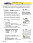
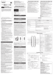
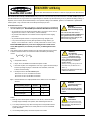
MINI-SCREEN® with Muting
System Semi-Annual Checkout Procedure for Latch and Trip Systems with Mute Function
This checkout must be done by a Qualified Person who possesses all of the manufacturer-provided information on the MINI-SCREEN System and
guarded machine and who, by possession of a recognized degree or certificate of professional training or who, by extensive knowledge, training, or
experience, has successfully demonstrated the ability to solve problems relating to the installation, operation, and maintenance of optoelectronic
machine guards. A copy of the test results should be kept in the employer’s files.
The Qualified Person must:
1)
Examine the guarded machine to verify that it is of a type and design that is compatible with
the MINI-SCREEN System. MINI-SCREEN Systems MAY NOT BE USED with the following:
• Any machine that cannot be stopped immediately after a stop signal is issued, such as
single stroke (also known as “full-revolution”) clutched machinery.
• Any machine with inadequate or inconsistent machine response time and stopping
performance.
• Any machine that ejects materials or component parts through the light screen.
!
WARNING . . .
Do Not Use Machine Until
System Is Working Properly
If all of the described checks cannot be
verified, DO NOT USE the MINI-SCREEN System
or the guarded machine until the defect or
problem has been corrected. Doing so could
result in serious injury or death.
• In any environment likely to adversely affect photoelectric sensing efficiency (for
example, corrosive chemicals or fluids or unusually severe levels of smoke or dust).
Banner MINI-SCREEN Systems may not be used as tripping devices to initiate machine
motion (PSDI applications) on mechanical power presses, per OSHA regulation 29 CFR
1910.217.
2)
Verify that the minimum separation distance from the closest hazard point of the guarded
machine to the defined area is not less than the distance calculated by the following
formula.
Ds = K x (Ts + Tr ) + Dpf
where:
Ds = the separation distance;
K
= 63" per second, the OSHA-recommended hand speed constant1
Ts = the overall stop time, from the application of the “stop” signal to the final ceasing of
all motion (including stop times of all relevant control elements, measured at
maximum machine velocity)2
Tr
= the response time of the MINI-SCREEN System:
.058 seconds for 4.5" to 16" emitters and receivers
.070 seconds for 20" to 32" emitters and receivers
.082 seconds for 36" to 48" emitters and receivers
!
Floating blanking OFF
30' Range
Sensors
Dpf = 1.6"
60' Range
Sensors
Dpf = 2.5"
1-beam blanking ON
Dpf = 3.3"
Dpf = 4.2"
2-beam blanking ON
Dpf = 5.0"
Dpf = 5.9"
Hard Guarding
If any object to be ignored by
fixed blanking does not
completely prevent access to the danger
point(s), install hard guarding to prevent
access past the object, or increase the
separation distance.
Openings in the hard guarding material must
meet OSHA criteria (see OSHA 1910.217,
Table O-10).
Failure to do so could lead to serious injury
or death. See Section 3.2.2.
Dpf = the added distance due to depth penetration factor; OSHA 1910.217 and ANSI B11
standards:
Floating Blanking Program3
WARNING . . .
WARNING . . .
!
Calculate the Separation
Distance Carefully
Failure to maintain appropriate separation
distance can result in serious bodily injury
or death.
NOTES:
WARNING . . .
1) Although studies indicate speeds of 63"/sec to over 100"/sec, consider all factors,
including the physical ability of the operator, when determining the value of K.
Shock Hazard
2) Ts is usually measured by a stop-time measuring device. If the specified machine
stop time is used, add at least 20% as a safety factor to account for clutch/brake
system deterioration.
A shock hazard exists while
the control box door is open.
Before continuing, verify that the door is
closed and latched.
3) Use of floating blanking always causes the required Ds to increase.
Printed in USA
05/00
P/N 62056
MINI-SCREEN® with Muting
Semi-Annual Checkout
3)
Verify that access to any dangerous parts of the guarded machine is not possible from any
direction not protected by the MINI-SCREEN System, hard guarding, or supplemental
guarding, and verify that all supplemental guarding devices and hard guarding are in place
and operating properly.
4)
Verify that it is not possible for a person to stand between the defined area and the
dangerous parts of the guarded machine. Or, verify that supplemental safeguarding (per
ANSI B11 safety requirements or other appropriate standards) is in place and functioning
properly in any space between the defined area and any danger point large enough to
allow a person to stand undetected by the MINI-SCREEN System.
5)
Examine the electrical wiring connections between the MINI-SCREEN output relays and the
guarded machine’s control elements to verify the requirements stated in Section 3.5.13 of
the manual.
6)
Test the effectiveness of the MINI-SCREEN System with system power ON. Select the
proper test piece based on system configuration, per the following chart:
Floating
Blanking Program
Standard Series
Emitters and Receivers
V-Series
Emitters and Receivers
OFF
STP-2, 19.1 mm (0.75") dia.
STP-4, 31.8 mm (1.25") dia.
1-beam
STP-4, 31.8 mm (1.25" ) dia.
STP-5, 57.5 mm (2.25") dia.
2-beam
STP-3, 44.5 mm (1.75") dia.
STP-9, 82.6 mm (3.25") dia.
a)
Figure 1. MINI-SCREEN trip test
Verify that the MINI-SCREEN System is in RUN mode
• Green and yellow Light Screen and System status indicators ON.
• The green Light Screen indicator will flash if blanking is programmed. Ensure
muting is not enabled.
See user’s manual, Section 5.1 for Key Reset procedure.
b)
With the guarded machine at rest, slowly pass the test piece downward through the
defined area at three points, perpendicular to the defined area: close to the receiver,
close to the emitter, and midway between them. Verify that while the test piece is
within the defined area:
• The red Light Screen status indicator comes ON and remains ON
• The green System status indicator is OFF
Remove the test piece from the defined area and verify:
• The green Light Screen status indicator comes ON
If the green Light Screen indicator comes ON at any time when the test piece is
within the defined area, check for reflective surfaces, or unguarded areas created by
use of fixed blanking (see Warnings). Do not continue until the situation is
corrected. (See Manual Sections 3.2.2 and 3.2.4.) Perform a System Key Reset to
reset the latch after each pass of the test piece, on latch models.
c)
Ensure that muting is not enabled, and initiate machine motion of the guarded
machine. While the machine is moving, insert the test piece into the defined area
(perpendicular to it). Do not attempt to insert the test piece into the dangerous
parts of the machine. As the test piece enters the defined area at any time during
machine motion, the dangerous parts of the machine should come to a stop with no
apparent delay. Remove the test piece from the defined area and perform a System
Key Reset. Verify that:
• The machine does not automatically restart, and
• The initiation devices must be engaged to restart the machine
d)
With the guarded machine at rest, insert the test piece into the defined area and
verify that:
• The guarded machine cannot be put into motion while the test piece is within the
defined area.
page 2
Banner Engineering Corp. • Minneapolis, U.S.A.
www.bannerengineering.com • Tel: 763.544.3164
MINI-SCREEN® with Muting
Semi-Annual Checkout
!
WARNING . . .
7)
Remove electrical power to the MINI-SCREEN System. Verify that:
• All output relays immediately de-energize, and can not be reactivated until power is reapplied and a System Key Reset is performed (unless both Auto Power-up features are ON).
8)
Test the machine stopping response time using an instrument designed for that purpose
to verify that it is the same or less than the overall system response time specified by the
machine manufacturer. (NOTE: Banner’s Applications Engineering Department can recommend a suitable instrument.)
Reflective Surfaces
A reflective surface (a shiny
machine surface or a shiny
workpiece) may reflect sensing light around an
object in the defined area, preventing that
object from being detected. This potentially
dangerous condition is discovered using the trip
test.
If any decrease in machine braking ability has occurred, make the necessary clutch/brake
repairs, readjust Ds appropriately, and re-perform this procedure. If the separation distance
has changed, record the new distance on the daily checkout card, p/n 62055.
When this condition is discovered, eliminate
the problem reflection(s):
9)
• If possible, relocate the sensors to move the
defined area away from the reflective
surface(s), being careful to retain at least the
required separation distance.
10) Inspect the guarded machine to verify that there are no other mechanical or structural
problems that would prevent the machine from stopping or assuming an otherwise safe
condition when signalled to do so by the MINI-SCREEN System.
• Otherwise, paint, mask, or roughen the
interfering shiny surface to reduce its
reflectivity.
• Repeat the trip test to verify that these
changes have eliminated the problem
reflection(s). If the workpiece is especially
reflective and comes close to the defined
area, perform the trip test with the shiny
workpiece in place. See Manual Section 3.2.4.
Examine and test the machine primary control elements (MPCEs) to verify that they are
functioning correctly and are not in need of maintenance or replacement.
11) Inspect the machine controls and connections to the MINI-SCREEN System. Verify that
no modifications have been made which adversely affect the system.
12) If the Muting feature is used:
Ensure that the MINI-SCREEN Light Screen and System have been reset and the green and
yellow Light Screen and System status indicators are ON. If the yellow System status indicator
is double flashing (indicating a latched condition), perform a System Key Reset. At any time, if
one or both red status indicators begin to flash, an internal lockout condition exists. Refer to
manual, Section 5.1 to determine the cause of the lockout.
During this checkout procedure, at all times ensure that personnel are not exposed to any
hazard.
Initiate a normal mute cycle. Verify:
• Mute indicator – comes ON
If not, check the indicator and its wiring, verify that the mute enable input is closed, and check
the System Diagnostic Display for error codes.
Interrupt the safety light screen with the test piece selected in step 6. Verify:
• Red Light Screen status indicator – comes ON
• Green Light Screen indicator – OFF
• Yellow Light Screen indicator – Flashing or OFF
• Green and yellow System status indicators – ON
NOTE: If the 30-second or 60-second Backdoor Timer feature is selected, the System
Diagnostic Display will begin to count down; otherwise a flashing dash will appear on
the display.
Clear the safety light screen (before the Backdoor Timer expires) and verify:
• Green and yellow Light Screen status indicators – ON
Clear (or deactivate) the mute devices and verify:
• Mute indicator – OFF
• Green and yellow System status indicators – ON
Verify that it is not possible for an individual to trigger the mute devices (block both
photoelectric beams or actuate both switches) to initiate a mute and then pass through the
defined area without being detected and a subsequent stop command being issued to the
machine. Do not expose any individual to hazard while attempting to initiate a mute cycle.
Verify that it is not possible for personnel to pass in front of, behind, or next to the target
object without being detected and without a stop command being issued to the machine.
If One-Way (directional) Muting has been selected, verify that a mute can not be initiated by
blocking (or activating) terminals M3 and M4 before M1 and M2.
Banner Engineering Corp. • Minneapolis, U.S.A.
www.bannerengineering.com • Tel: 763.544.3164
page 3
MINI-SCREEN® with Muting
Semi-Annual Checkout
14) If the Override feature is used:
Verify that the Light Screen controller is in RUN mode and the System has been reset
• Green and yellow Light Screen and System status indicators ON
• FSDs closed.
See manual, Figures 6-1 and 6-2
During this checkout procedure, at all times ensure that personnel are not exposed to any
hazard.
• Verify that the positioning of the Override switches allows the operator full view of the
entire area being guarded by the safety light screen. Verify that the location is not within
reach from inside the safeguarded space.
With muting de-activated, interrupt the safety light screen with the test piece selected in
step 5 and verify:
• Red Light Screen status indicator – comes ON
• Green Light Screen indicator – OFF
• Yellow Light Screen indicator – Flashing
• Green System status indicator – OFF
• Yellow System status indicator – ON
Three seconds after interrupting the light screen, initiate an override cycle: turn both
Override switches to ON simultaneously (hold in the ON position if necessary).
While the light screen is interrupted, verify:
• Both red status indicators – ON
• Yellow Light Screen indicator – Flashing (rate proportional to number of clear beams)
• Green System status indicator – ON
• FSDs – closed
Verify that the Override drops out after 10 seconds. To initiate another override cycle, return
switches to the OFF (open) condition, wait 3 seconds, and then simultaneously re-close the
Override switches.
Remove all obstructions from the light screen (and perform a System Key Reset on
latching models). Verify:
• Green and yellow System status indicators – ON
• FSDs – closed
If one or both red status indicator(s) begins to flash when the system goes into RUN mode,
an internal lockout condition exists. Refer to Section 5.1 of the manual to determine the cause
of the lockout.
If all checks cannot be verified, shut machine down and do not use until the problem(s) has
been corrected. Refer to user’s manual, Section 5.
Banner Engineering Corp., 9714 Tenth Ave. No., Minneapolis, MN 55441 • Phone: 763.544.3164 • www.bannerengineering.com • E-mail: [email protected]