1
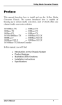
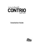
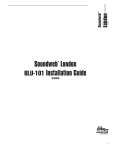
Soundweb London BLU-BIB Installation Guide TM 18-0755-A 1 IMPORTANT SAFETY INSTRUCTIONS WARNING FOR YOUR PROTECTION READ THE FOLLOWING: DECLARATION OF CONFORMITY KEEP THESE INSTRUCTIONS HEED ALL WARNINGS Manufacturer’s Name: BSS Audio Manufacturer’s Address: 8760 S. Sandy Parkway Sandy, Utah 84070, USA declares that the product: Product name: BLU-BIB Note: Product name may be suffixed by the EU. Product option: all (requires Class II power adapter that conforms to the requirements of EN60065, EN60742, or equivalent.) conforms to the following Product Specifications: Safety: IEC 60065 -01+Amd. 1 EMC: EN 55022:2006 EN 55024:1998 FCC Part 15 Supplementary Information: The product herewith complies with the requirements of the: Low Voltage Directive 2006/95/EC EMC Directive 2004/108/EC. RoHS Directive 2002/95/EC WEEE Directive 2002/96/EC With regard to Directive 2005/32/EC and EC Regulation 1275/2008 of 17 December 2008, this product is designed, produced, and classified as Professional Audio Equipment and thus is exempt from this Directive. Roger Johnsen Vice-President of Engineering 8760 S. Sandy Parkway Sandy, Utah 84070, USA Date: June 9, 2010 European Contact: Your local BSS Audio Sales and Service Office or Harman Music Group 8760 South Sandy Parkway Sandy, Utah 84070, USA Ph: (801) 566-8800 Fax: (801) 566-7583 U.K. MAINS PLUG WARNING A molded mains plug that has been cut off from the cord is unsafe. Discard the mains plug at a suitable disposal facility. NEVER UNDER ANY CIRCUMSTANCES SHOULD YOU INSERT A DAMAGED OR CUT MAINS PLUG INTO A 13 AMP POWER SOCKET. Do not use the mains plug without the fuse cover in place. Replacement fuse covers can be obtained from your local retailer. Replacement fuses are 13 amps and MUST be ASTA approved to BS1362. FOLLOW ALL INSTRUCTIONS The symbols shown above are internationally accepted symbols that warn of potential hazards with electrical products. The lightning flash with arrowpoint in an equilateral triangle means that there are dangerous voltages present within the unit. The exclamation point in an equilateral triangle indicates that it is necessary for the user to refer to the owner’s manual. These symbols warn that there are no user serviceable parts inside the unit. Do not open the unit. Do not attempt to service the unit yourself. Refer all servicing to qualified personnel. Opening the chassis for any reason will void the manufacturer’s warranty. Do not get the unit wet. If liquid is spilled on the unit, shut it off immediately and take it to a dealer for service. Disconnect the unit during storms to prevent damage. ELECTROMAGNETIC COMPATIBILITY This device complies with part 15 of the FCC Rules and the Product Specifications noted on the Declaration of Conformity. Operation is subject to the following two conditions: •this device may not cause harmful interference, and •this device must accept any interference received, including interference that may cause undesired operation. Operation of this unit within significant electromagnetic fields should be avoided. • use only shielded interconnecting cables. Safety Instructions Notice For Customers If Your Unit Is Equipped With A Power Cord. The apparatus shall not be exposed to dripping or splashing liquid and no object filled with liquid, such as vases, shall be placed on the apparatus CLEAN ONLY WITH A DRY CLOTH. DO NOT BLOCK ANY OF THE VENTILATION OPENINGS. INSTALL IN ACCORDANCE WITH THE MANUFACTURER’S INSTRUCTIONS. DO NOT INSTALL NEAR ANY HEAT SOURCES SUCH AS RADIATORS, HEAT REGISTERS, STOVES, OR OTHER APPARATUS (INCLUDING AMPLIFIERS) THAT PRODUCE HEAT. ONLY USE ATTACHMENTS/ACCESSORIES SPECIFIED BY THE MANUFACTURER. UNPLUG THIS APPARATUS DURING LIGHTNING STORMS OR WHEN UNUSED FOR LONG PERIODS OF TIME. Do not defeat the safety purpose of the polarized or grounding-type plug. A polarized plug has two blades with one wider than the other. A grounding type plug has two blades and a third grounding prong. The wide blade or third prong are provided for your safety. If the provided plug does not fit your outlet, consult an electrician for replacement of the obsolete outlet. Protect the power cord from being walked on or pinched particularly at plugs, convenience receptacles, and the point where they exit from the apparatus. Use only with the cart stand, tripod bracket, or table specified by the manufacture, or sold with the apparatus. When a cart is used, use caution when moving the cart/apparatus combination to avoid injury from tip-over. Refer all servicing to qualified service personnel. Servicing is required when the apparatus has been damaged in any way, such as power-supply cord or plug is damaged, liquid has been spilled or objects have fallen into the apparatus, the apparatus has been exposed to rain or moisture, does not operate normally, or has been dropped. WARNING: THIS APPLIANCE SHALL BE CONNECTED TO A MAINS SOCKET OUTLET WITH A PROTECTIVE EARTHING CONNECTION. The cores in the mains lead are coloured in accordance with the following code: GREEN and YELLOW - Earth BLUE - Neutral BROWN - Live As colours of the cores in the mains lead of this appliance may not correspond with the coloured markings identifying the terminals in your plug, proceed as follows: • The core which is coloured green and yellow must be connected to the terminal in the plug marked with the letter E, or with the earth symbol, or coloured green, or green and yellow. • The core which is coloured blue must be connected to the terminal marked N or coloured black. • The core which is coloured brown must be connected to the terminal marked L or coloured red. This equipment may require the use of a different line cord, attachment plug, or both, depending on the available power source at installation. If the attachment plug needs to be changed, refer servicing to qualified service personnel who should refer to the table below. The green/yellow wire shall be connected directly to the units chassis. CONDUCTOR L N LIVE NEUTRAL E EARTH GND WIRE COLOR Normal Alt BROWN BLACK BLUE WHITE GREEN/ GREEN YEL WARNING: If the ground is defeated, certain fault conditions in the unit or in the system to which it is connected can result in full line voltage between chassis and earth ground. Severe injury or death can then result if the chassis and earth ground are touched simultaneously. POWER ON/OFF SWITCH: For products provided with a power switch, the power switch DOES NOT break the connection from the mains. MAINS DISCONNECT: The plug shall remain readily operable. For rackmount or installation where plug is not accessible, an all-pole mains switch with a contact separation of at least 3 mm in each pole shall be incorporated into the electrical installation of the rack or building. FOR UNITS EQUIPPED WITH EXTERNALLY ACCESSIBLE FUSE RECEPTACLE: Replace fuse with same type and rating only. MULTIPLE-INPUT VOLTAGE: This equipment may require the use of a different line cord, attachment plug, or both, depending on the available power source at installation. Connect this equipment only to the power source indicated on the equipment rear panel. To reduce the risk of fire or electric shock, refer servicing to qualified service personnel or equivalent. If connected to a 240V supply, a suitable CSA/UL certified power cord shall be used for this supply. POWER ADAPTER: Ensure a minimum of 8 inches of clearance and ventilation around the adapter. If you want to dispose this product, do not mix it with general household waste. There is a separate collection system for used electronic products in accordance with legislation that requires proper treatment, recovery and recycling. Private household in the 25 member states of the EU, in Switzerland and Norway may return their used electronic products free of charge to designated collection facilities or to a retailer (if you purchase a similar new one). For Countries not mentioned above, please contact your local authorities for a correct method of disposal. By doing so you will ensure that your disposed product undergoes the necessary treatment, recovery and recycling and thus prevent potential negative effects on the environment and human health. Front panel BLU-BIB +48V The +48V LED illuminates for each channel when the channel is selected. Signal The Signal LED illuminates for each channel where a signal is present. dB Gain The dB Gain LEDs indicate the gain setting for the selected channel. Power The Power LED illuminates when the BLU-BIB device is powered on. When a valid Digital Audio Bus connection is present, the Power LED will illuminate. When no valid Digital Audio Bus connections are present, the Power LED will flash on and off. Channel Buttons Each Channel Button can be pressed to select that channel. 48 Button While in Edit Mode, this button enables/disables +48V phantom for the selected channel dB Gain Up/Down Buttons While in Edit Mode, pressing either button steps through the gain setting for the selected channel. Rear panel BLU-BIB 12VDC Power Adapter The BLU-BIB Break-In Box input expanders are powered by a 12V DC adapter that is included with the device. Use only the adapter provided. BLU link In/Out The Soundweb London Digital Audio Bus (also known as “BLU link”) is a high bandwidth, fault-tolerant bus of 256 channels at 48kHz and 128 channels at 96kHz. Devices are connected, using Cat 5e or Cat 6 cable, in a ring from the OUT connector of one device to the IN connector of the adjacent device. The distance between devices in the ring can be up to 100m on Cat 5e or Cat 6 or up to 10km on single mode fiber using the MC-1 fiber media converter. The ring topology allows any single cable fault without loss of channels. All devices within a given Digital Audio Bus ring must be configured for the same sample rate. The sample rate of the BLU-BIB device is automatically configured based on remotely configured devices within the Digital Audio Bus ring. Channel Select The BLU-BIB input channels are easily configured by six DIP switches located on the rear of the device, which select a range of 8 consecutive channels from the Digital Audio Bus. Input channel assignments are configured by DIP switch selection only. Do not give more than one BLU-BIB device within the same Digital Audio Bus ring the same DIP switch settings. Doing so will result in only one of the devices passing audio onto the Digital Audio Bus. Each BLU-BIB should have unique DIP switch settings. The BLU-BIB is not configured by HiQnet™ London Architect. To determine the DIP switch settings 3 required for assignment to given channels on the Digital Audio Bus, see page 6. The same information is also available on the top lid of the BLU-BIB chassis. Analog Input 1-8 The 8 analog mic/line level inputs utilize the same terminal block connectors as the other members of the Soundweb London family. Operating Instructions The BLU-BIB operates in three different modes, which are accessed via the front panel controls. Stealth Mode Stealth Mode prevents the user from making any changes to the input gain and Phantom Power on any channels. Stealth Mode also prevents all LED’s from illuminating (except for the Power LED), which is useful for installations that require low-profile operation of the BLU-BIB. To Enter Stealth Mode (from Normal Mode) • Hold Ch. Buttons 1 + 4 for three seconds To Exit Stealth Mode (to Normal Mode) • Hold Ch. Buttons 1 + 4 for three seconds • The Signal LEDs blink YELLOW • Enter the lockout code: 1,2,3,4 • If the code is not entered within 30 seconds, the BLU-BIB will return to the regular operation of Stealth Mode Normal Mode Normal Mode prevents the user from making any changes to the input gain and Phantom Power on any channels. Normal Mode also provides indication of signal presence, applied input gain and Phantom Power. To determine a channel’s applied gain: • Select a channel by pressing one of the Ch. Buttons (1 through 8) • A GREEN LED will illuminate behind one of the gain level indicators (0, 6, 12, 18, 24, 30, 36, 42, 48) Edit Mode Edit Mode allows the user to adjust each channel’s input gain and Phantom Power. To adjust the applied gain or enable/disable Phantom Power on a given channel: • Select a channel by pressing one of the Ch. Buttons (1 through 8) • The Signal LED above that channel will blink YELLOW • Use the Up / Down buttons to adjust gain • Use the 48 Button to enable or disable Phantom Power 4 To enter Edit Mode (from Normal Mode): • Hold Ch. Buttons 1 + 8 for one second • The Signal LEDs flash GREEN twice • After 60 seconds of inactivity, Normal Mode will automatically be entered To exit Edit Mode (to Normal Mode): • Hold Ch. Buttons 1 + 8 for one second • The Signal LEDs flash RED twice The following diagram shows the actions required to enter and exit the various modes of operation: 5 T e c h n i c a l S p e c i f i c at i o n s : Front Panel LED Indicators: Analog Inputs: Mic/Line Inputs: Input Impedance: Maximum Input Level: CMRR: Input Noise (E.I.N.): Phantom Power: A/D Latency Digital Audio Bus: Connectors: Maximum Cable Length: Maximum Number of Nodes: Latency: Pass Through Latency: Power and Dimensions: Mains Voltage: AC Power Input to Adapter: BTU Rating: Operating Temperature Range: Dimensions (H x W x D): Weight: CHANNELS DIP SWITCH SETTINGS Signal Preset/Clip (per input), 48V (per input), Gain (0/6/12/18/24/30/36/42/48dB), and Power 8 electronically balanced on Phoenix/Combicon removable screw connectors Nominal gain 0dB, electronically switchable up to +48dB, in 6dB steps 3.0kOhm +20dBu with 0dB input gain, +8dBu with 12dB gain >40dB at 1kHz <-123dBu typical with 150 Ohms source 48V nominal, selectable per input 37/Fs [0.77ms@48k, 0.39ms@96k] 2 x RJ45 Ethernet connectors 100m/300ft on Category 5e cable between devices 60 4/Fs [0.08ms@48k, 0.04ms@96k] 2/Fs [0.04ms@48k, 0.02ms@96k] 12V DC external power supply included 19W <65 BTU/hr 5(41) to 35(95) degrees C (degrees F) 1.65” x 8.63” x 7.75” (42mm x 219mm x 197mm) 2.96lbs / 1.34kg CHANNELS DIP SWITCH SETTINGS CHANNELS DIP SWITCH SETTINGS CHANNELS 1 to 8 65 to 72 129 to 136 193 to 200 9 to 16 73 to 80 137 to 144 201 to 208 17 to 24 81 to 88 145 to 152 209 to 216 25 to 32 89 to 96 153 to 160 217 to 224 33 to 40 97 to 104 161 to 168 225 to 232 41 to 48 105 to 112 169 to 176 233 to 240 49 to 56 113 to 120 177 to 184 241 to 248 57 to 64 121 to 128 185 to 192 249 to 256 DIP SWITCH SETTINGS Note: Lowest channel of 8 channel range is always input 1 of BLU-BIB 6 7 BSS Audio 8760 South Sandy Parkway Sandy, Utah 84070 801-566-8800 www.bssaudio.com Printed in the USA