1
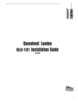
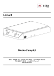
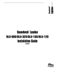
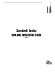
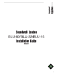
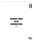
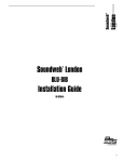
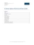
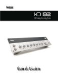
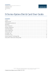
Soundweb London
BLU-50
Installation Guide
TM
5040341-B
IMPORTANT SAFETY INSTRUCTIONS
WARNING FOR YOUR PROTECTION
READ THE FOLLOWING:
READ THESE INSTRUCTIONS.
KEEP THESE INSTRUCTIONS.
HEED ALL WARNINGS.
The symbols shown above are internationally accepted symbols that warn
of potential hazards with electrical products. The lightning flash with
arrowpoint in an equilateral triangle means that there are dangerous
voltages present within the unit. The exclamation point in an equilateral
triangle indicates that it is necessary for the user to refer to the owner’s
manual.
FOLLOW ALL INSTRUCTIONS.
These symbols warn that there are no user serviceable parts inside the
unit. Do not open the unit. Do not attempt to service the unit yourself.
Refer all servicing to qualified personnel. Opening the chassis for any
reason will void the manufacturer’s warranty. Do not get the unit wet. If
liquid is spilled on the unit, shut it off immediately and take it to a dealer
for service. Disconnect the unit during storms to prevent damage.
DO NOT BLOCK ANY OF THE VENTILATION OPENINGS. INSTALL IN ACCORDANCE WITH THE
MANUFACTURER’S INSTRUCTIONS.
The following is indicative of low
altitude use; do not use this product
above 2000m.
U.K. MAINS PLUG WARNING
A molded mains plug that has been cut off from the cord is
unsafe. Discard the mains plug at a suitable disposal facility.
NEVER UNDER ANY CIRCUMSTANCES SHOULD YOU
INSERT A DAMAGED OR CUT MAINS PLUG INTO A
13 AMP POWER SOCKET.
Do not use the mains plug without the fuse cover in place.
Replacement fuse covers can be obtained from your local retailer.
Replacement fuses are 13 amps and MUST be ASTA approved to
BS1362.
If you want to dispose this product, do not mix it with general household waste. There is a separate collection system
for used electronic products in accordance with legislation that requires proper treatment, recovery and recycling.
Private households in the 25 member states of the EU, in Switzerland and Norway may return their used electronic products free
of charge to designated collection facilities or to a retailer (if you purchase a similar new one).
For Countries not mentioned above, please contact your local authorities for a correct method of disposal.
By doing so you will ensure that your disposed product undergoes the necessary treatment, recovery and recycling and thus prevent
potential negative effects on the environment and human health.
DO NOT USE THIS APPARATUS NEAR WATER.
CLEAN ONLY WITH A DRY CLOTH.
FOR INDOOR USE ONLY.
DO NOT INSTALL NEAR ANY HEAT SOURCES SUCH AS RADIATORS, HEAT REGISTERS, STOVES, OR
OTHER APPARATUS (INCLUDING AMPLIFIERS) THAT PRODUCE HEAT.
ONLY USE ATTACHMENTS/ACCESSORIES SPECIFIED BY THE MANUFACTURER.
UNPLUG THIS APPARATUS DURING LIGHTNING STORMS OR WHEN UNUSED FOR LONG PERIODS
OF TIME.
Do not defeat the safety purpose of the polarized or grounding-type plug. A polarized plug has two
blades with one wider than the other. A grounding type plug has two blades and a third grounding
prong. The wide blade or third prong are provided for your safety. If the provided plug does not fit
your outlet, consult an electrician for replacement of the obsolete outlet.
Protect the power cord from being walked on or pinched particularly at plugs, convenience
receptacles, and the point where they exit from the apparatus.
Use only with the cart stand, tripod bracket, or table specified by the
manufacture, or sold with the apparatus. When a cart is used, use caution
when moving the cart/apparatus combination to avoid injury from tip-over.
Refer all servicing to qualified service personnel. Servicing is required when the apparatus has
been damaged in any way, such as power-supply cord or plug is damaged, liquid has been spilled
or objects have fallen into the apparatus, the apparatus has been exposed to rain or moisture, does
not operate normally, or has been dropped.
POWER ON/OFF SWITCH: The Power switch used in this piece of equipment DOES NOT break the
connection from the mains.
MAINS DISCONNECT: The plug shall remain readily operable. For rack-mount or installation where
plug is not accessible, an all-pole mains switch with a contact separation of at least 3 mm in each
pole shall be incorporated into the electrical installation of the rack or building.
If connected to 240V supply, a suitable CSA/UL certified power cord shall be used for this supply.
This Equipment is intended for rack mount use only.
IMPORTANT SAFETY INSTRUCTIONS
ELECTROMAGNETIC COMPATIBILITY
This device complies with part 15 of the FCC Rules and the Product
Specifications noted on the Declaration of Conformity. Operation
is subject to the following two conditions:
• this device may not cause harmful interference, and
• this device must accept any interference received, including
interference that may cause undesired operation.
Operation of this unit within significant electromagnetic fields should be
avoided.
• use only shielded interconnecting cables.
DECLARATION OF CONFORMITY
Manufacturer’s Name:
BSS Audio
Manufacturer’s Address:
10653 South River Front Parkway
Suite 300
South Jordan, Utah 84095, USA
declares that the product:
Product name:
Product option:
SAFETY INSTRUCTIONS
BLU 50
Note: Product name may be suffixed by the EU.
None
conforms to the following Product Specifications:
NOTICE FOR CUSTOMERS IF YOUR UNIT IS EQUIPPED WITH A POWER CORD.
Safety:
WARNING: THIS APPLIANCE SHALL BE CONNECTED TO A MAINS SOCKET OUTLET WITH A PROTECTIVE
EARTHING CONNECTION.
EMC:EN 55022:2006
EN 55024:1998
FCC Part 15
THE CORES IN THE MAINS LEAD ARE COLOURED IN ACCORDANCE WITH THE FOLLOWING CODE:
GREEN AND YELLOW - EARTH
BLUE - NEUTRAL
BROWN - LIVE
AS COLOURS OF THE CORES IN THE MAINS LEAD OF THIS APPLIANCE MAY NOT CORRESPOND WITH THE
COLOURED MARKINGS IDENTIFYING THE TERMINALS IN YOUR PLUG, PROCEED AS FOLLOWS:
• T HE CORE WHICH IS COLOURED GREEN AND YELLOW MUST BE CONNECTED TO THE TERMINAL IN
THE PLUG MARKED WITH THE LETTER E, OR WITH THE EARTH SYMBOL, OR COLOURED GREEN, OR
GREEN AND YELLOW.
• THE CORE WHICH IS COLOURED BLUE MUST BE CONNECTED TO THE TERMINAL MARKED N OR
COLOURED BLACK.
• THE CORE WHICH IS COLOURED BROWN MUST BE CONNECTED TO THE TERMINAL MARKED L OR
COLOURED RED.
THIS EQUIPMENT MAY REQUIRE THE USE OF A DIFFERENT LINE CORD, ATTACHMENT PLUG, OR BOTH,
DEPENDING ON THE AVAILABLE POWER SOURCE AT INSTALLATION. IF THE ATTACHMENT PLUG NEEDS TO
BE CHANGED, REFER SERVICING TO QUALIFIED SERVICE PERSONNEL WHO SHOULD REFER TO THE TABLE
BELOW. THE GREEN/YELLOW WIRE SHALL BE CONNECTED DIRECTLY TO THE UNITS CHASSIS.
CONDUCTOR
L
N
LIVE
NEUTRAL
E
EARTH GND
WIRE COLOR
Normal
Alt
BROWN
BLACK
BLUE
WHITE
GREEN/YEL
IEC 60065 -01+Amd 2
Supplementary Information:
The product herewith complies with the requirements of the:
Low Voltage Directive 2006/95/EC
EMC Directive 2004/108/EC.
RoHS Directive 2011/65/EC
WEEE Directive 2002/96/EC
With regard to Directive 2005/32/EC and EC Regulation 1275/2008 of
17 December 2008, this product is designed, produced, and classified as
Professional Audio Equipment and thus is exempt from this Directive.
Rex C. Reed
Director, Engineering
Signal Processing
10653 South River Front Parkway
Suite 300
South Jordan, Utah 84095, USA
Date: March 7, 2014
GREEN
WARNING: IF THE GROUND IS DEFEATED, CERTAIN FAULT CONDITIONS IN THE UNIT OR IN THE SYSTEM TO WHICH IT IS CONNECTED CAN RESULT IN FULL LINE VOLTAGE BETWEEN CHASSIS AND EARTH
GROUND. SEVERE INJURY OR DEATH CAN THEN RESULT IF THE CHASSIS AND EARTH GROUND ARE
TOUCHED SIMULTANEOUSLY.
WARNING:
• APPARATET MÅ TILKOPLES JORDET STIKKONTAKT.
• APPARATEN SKALL ANSLUTAS TILL JORDAT UTTAG.
• LAITE ON LIITETTÄVÄ SUOJAKOSKETTIMILLA VARUSTETTUUN PISTORASIAAN.
European Contact: Your local BSS Audio Sales and Service Office or:
Harman Signal Processing
10653 South River Front Parkway
Suite 300
South Jordan, Utah 84095, USA
Ph: (801) 566-8800
Fax: (801) 568-7583
CONSIGNES DE SÉCURITÉ IMPORTANTES
AVERTISSEMENT POUR VOTRE SÉCURITÉ
LIRE ATTENTIVEMENT :
LIRE CES CONSIGNES.
CONSERVER CES CONSIGNES.
RESPECTER TOUS LES AVERTISSEMENTS.
SUIVRE TOUTES LES CONSIGNES.
Les symboles illustrés ci-dessus sont des symboles acceptés
internationalement qui avertissent des dangers potentiels relatifs à
l’utilisation de produits électriques. Le voyant clignotant avec une flèche
dans un triangle équilatéral signifie la présence de tensions dangereuses
dans l'appareil. Le point d’exclamation dans un triangle équilatéral
indique que l’utilisateur doit se référer au manuel d'utilisation.
Ces symboles indiquent qu’il n’y a aucune pièce utilisable par l’utilisateur
à l’intérieur de l’appareil. Ne pas ouvrir l’appareil. Ne pas essayer de
réparer soi-même l’appareil. Confier toute réparation à du personnel
qualifié. Ouvrir la structure de l’appareil pour quelque raison que ce soit
annulera la garantie du fabricant. Ne pas mouiller l’appareil. Si du liquide
est renversé sur l’appareil, fermer immédiatement l’appareil et l’apporter
chez un réparateur. Débrancher l’appareil pendant les tempêtes afin
d’éviter des dommages.
Ce qui suit est représentatif d’une
utilisation à basse altitude ; ne pas
utiliser ce produit au-dessus de 2000 m.
AVERTISSEMENT CONCERNANT
LA FICHE SECTEUR
Une fiche secteur moulée qui a été coupée du cordon est dangereuse.
Jeter la fiche secteur dans un centre de déchets adapté.
VOUS NE DEVEZ EN AUCUNE CIRCONSTANCE INSÉRER
UNE FICHE ENDOMMAGÉE OU COUPÉE DANS UNE PRISE
SECTEUR 13 AMP.
Ne pas utiliser la fiche secteur si le couvercle du coffret à fusibles n'est
pas bien en place. Vous pouvez vous procurer des capots de fusible de
rechange auprès de votre détaillant local. Les fusibles de remplacement
sont de 13 A et DOIVENT être approuvés ASTA, BS1362.
Ne pas jeter ce produit avec les ordures ménagères. Il existe un système de collecte sélective pour les produits
électroniques usagés en conformité avec les lois en vigueur en matière de traitement, de récupération et de recyclage.
Dans les 25 États membres de l'UE, en Norvège et en Suisse, les ménages peuvent envoyer leurs produits électroniques
usagés sans frais vers des centres de collecte sélective ou chez un distributeur (contre l'achat d'un nouveau produit).
Contacter les autorités locales pour connaître les procédures de traitement des déchets adaptées dans les pays non
mentionnés
ci-dessus.
Non seulement cette précaution vous permettra d’être sûr que votre produit est correctement traité, récupéré et recyclé,
mais elle vous évitera également de nuire involontairement à l'environnement et à la santé humaine.
NE PAS UTILISER CET APPAREIL PRÈS DE L’EAU.
NETTOYER UNIQUEMENT AVEC UN CHIFFON SEC.
POUR USAGE INTÉRIEUR UNIQUEMENT.
NE PAS OBSTRUER LES OUÏES D’AÉRATION. EFFECTUER L’INSTALLATION CONFORMÉMENT AUX
INSTRUCTIONS DU FABRICANT.
NE PAS INSTALLER À PROXIMITÉ DE SOURCES DE CHALEUR TELLES QUE DES RADIATEURS,
BOUCHES D’AÉRATION, PLAQUES CHAUFFANTES OU TOUT AUTRE APPAREIL (Y COMPRIS DES
AMPLIFICATEURS) DÉGAGEANT DE LA CHALEUR.
UTILISER UNIQUEMENT LES PIÈCES/ACCESSOIRES MENTIONNÉS PAR LE FABRICANT.
DÉBRANCHER L'APPAREIL AU COURS DES ORAGES OU EN CAS DE NON-UTILISATION PENDANT UNE
DURÉE PROLONGÉE.
Ne pas détériorer la sécurité de la fiche polarisée ou de la fiche de terre. Les fiches polarisées sont
équipées de deux bornes de largeurs différentes. Les fiches de terre comportent deux lames et une
troisième broche de mise à la terre. La broche la plus large ou troisième broche de mise à la terre
est prévue pour votre sécurité. Si la fiche fournie ne correspond pas à votre installation électrique,
faire appel à un électricien pour remplacer la prise hors normes.
Protéger le cordon d'alimentation contre les risques de piétinement ou de pincement, notamment
au niveau des fiches, des prises de courant et du point d'attache avec le matériel.
Utiliser uniquement le chariot, le support, le trépied ou la table spécifié(e)
par le fabricant ou vendu(e) avec le matériel. Si vous utilisez un chariot
pour déplacer l'appareil, soyez suffisamment prudent pour éviter une
éventuelle blessure consécutive au basculement du chariot et de sa charge.
Les réparations doivent être confiées à un technicien S.A.V. qualifié. Une réparation est nécessaire en
cas de dommage quelconque et en particulier en cas d'endommagement du cordon d’alimentation
ou de la fiche électrique, d'infiltration liquide, d'introduction involontaire d'un objet dans l'appareil,
d'exposition de l’appareil à la pluie ou à un milieu humide, de fonctionnement anormal ou de chute
de l'appareil.
INTERRUPTEUR MARCHE/ARRÊT : l'interrupteur d'alimentation de cet équipement NE coupe PAS
la connexion secteur.
DÉBRANCHEMENT DE L'APPAREIL : la prise de courant doit rester facilement accessible. Pour un
montage en rack ou une installation avec une prise inaccessible, un interrupteur omnipolaire à
distance d'ouverture de contact d'au moins 3 mm doit être intégré à l’installation électrique du
rack ou du local.
Si le matériel est relié à une alimentation de 240 V, utiliser impérativement un cordon d'alimentation
adapté certifié CSA/UL pour ce branchement.
Cet équipement est exclusivement destiné à un montage en rack.
CONSIGNES DE SÉCURITÉ IMPORTANTES
COMPATIBILITÉ ÉLECTROMAGNÉTIQUE Cet appareil est conforme au volet 15 des règles du FCC et aux
spécifications techniques évoquées dans la Déclaration de
conformité. Son fonctionnement est soumis aux deux conditions
suivantes :
• cet appareil ne doit pas causer d’interférences nuisibles et
• cet appareil doit accepter les interférences captées, y compris les
interférences susceptibles de nuire à son fonctionnement.
L’utilisation de cet appareil à proximité de champs électromagnétiques
puissants n’est pas recommandée.
• utiliser exclusivement des câbles d’interconnexion blindés.
CONSIGNES DE SÉCURITÉ
NOTICE ADRESSÉE AUX CONSOMMATEURS ÉQUIPÉS D’UN MATÉRIEL AVEC CORDON D’ALIMENTATION
FOURNI.
AVERTISSEMENT : CET APPAREIL DOIT ÊTRE BRANCHÉ SUR UNE PRISE SECTEUR DOTÉE D'UNE PROTECTION PAR MISE À LA TERRE.
LES COULEURS DES NOYAUX DANS LES FILS SECTEURS DOIVENT RESPECTER LES CODES SUIVANTS :
VERT ET JAUNE - TERRE
BLEU - NEUTRE
MARRON - PHASE
LES COULEURS DES NOYAUX DANS LES FILS SECTEURS DE CET APPAREIL PEUVENT NE PAS CORRESPONDRE AUX INSCRIPTIONS COLORÉES IDENTIFIANT LES TERMINAUX DANS VOTRE FICHE ; IL FAUT DONC
PROCÉDER DE LA FAÇON SUIVANTE :
• LE NOYAU VERT ET JAUNE DOIT ÊTRE BRANCHÉ AU TERMINAL DE LA FICHE OÙ APPARAÎT LA LETTRE E
OU LE SYMBOLE DE MISE À LA TERRE, OU AU TERMINAL VERT OU VERT ET JAUNE.
• LE NOYAU BLEU DOIT ÊTRE BRANCHÉ AU TERMINAL MARQUÉ D’UN N OU DE COULEUR NOIRE.
• LE NOYAU MARRON DOIT ÊTRE BRANCHÉ AU TERMINAL MARQUÉ D’UN L OU DE COULEUR ROUGE.
CE MATÉRIEL PEUT NÉCESSITER L’UTILISATION D’UN CORDON D’ALIMENTATION DIFFÉRENT ET/OU
D’UNE FICHE DE BRANCHEMENT DIFFÉRENTE SELON LA SOURCE D’ALIMENTATION DISPONIBLE À
L’INSTALLATION. SI LA FICHE DE BRANCHEMENT DOIT ÊTRE CHANGÉE, FAIRE APPEL À UN TECHNICIEN
QUALIFIÉ QUI DEVRA SE RÉFÉRER AU TABLEAU CI-DESSOUS. LE FIL VERT/JAUNE DOIT ÊTRE BRANCHÉ
DIRECTEMENT AU CHÂSSIS DE L'APPAREIL.
CONNECTEURS
L
N
PHASE
NEUTRE
E
TERRE
COULEUR DU FIL
normal
Alt
MARRON
NOIR
BLEU
BLANC
VERT/JAU
VERT
ATTENTION : UN DÉFAUT DE MISE À LA TERRE PEUT PROVOQUER CERTAINS DYSFONCTIONNEMENTS
DE L'APPAREIL OU DU SYSTÈME AUQUEL IL EST RELIÉ, POUVANT SE TRADUIRE PAR UNE TENSION COMPOSÉE ENTRE LA MASSE ET LA PRISE DE TERRE. CELA PEUT PROVOQUER DES BLESSURES SÉRIEUSES OU
FATALES SI LA MASSE ET LA PRISE DE TERRE SONT TOUCHÉES EN MÊME TEMPS.
ATTENTION : • APPARATET MÅ TILKOPLES JORDET STIKKONTAKT.
• APPARATEN SKALL ANSLUTAS TILL JORDAT UTTAG.
• LAITE ON LIITETTÄVÄ SUOJAKOSKETTIMILLA VARUSTETTUUN PISTORASIAAN.
DÉCLARATION DE CONFORMITÉ
Nom du fabricant :
BSS Audio
Adresse du fabricant :
10653 South River Front Parkway
Suite 300
South Jordan, Utah 84095, ÉTATS-UNIS déclare que le produit :
Nom du produit :
BLU 50
Remarque : Le nom du produit peut être suivi des lettres UE.
Option du produit :
Aucune
est conforme aux spécifications suivantes :
Sécurité :
CEI/IEC 60065:2001 + Amd 2
CEM :
EN 55022:2006 EN 55024:1998
Partie 15 des FCC
Informations complémentaires :
Ce produit est conforme aux exigences suivantes :
Directive sur la basse tension 2006/95/CE
Directive 2004/108/CE.
Directive RoHS 2011/65/UE
Directive DEEE 2002/96/CE Ce produit appartenant à la catégorie Matériel audio professionnel, il n'est
pas concerné par la directive 2005/32/CE ou par le règlement européen
1275/2008 du 17 décembre 2008.
Rex C. Reed
Directeur, Ingénierie
Traitement des signaux
10653 South River Front Parkway
Suite 300
South Jordan, Utah 84095, ÉTATS-UNIS Date : 7 mars 2014
Contact en Europe : votre revendeur BSS Audio local et le bureau d'assistance
de :
Harman Signal Processing
10653 South River Front Parkway
Suite 300
South Jordan, Utah 84095, ÉTATS-UNIS Tél. : (801) 566-8800
Fax : (801) 568-7583
Table of Contents
Regulatory Information����������������������������������������������������������������������������������������������������������� 1
Product Registration/Warranty����������������������������������������������������������������������������������������������� 1
Important User Information��������������������������������������������������������������������������������������������������� 1
Mechanical Installation����������������������������������������������������������������������������������������������������������� 1
Mounting The BLU-50������������������������������������������������������������������������������������������������������������� 2
Rack Mounting������������������������������������������������������������������������������������������������������������������������������������������������������2
Under-Table Mounting�������������������������������������������������������������������������������������������������������������������������������������������3
Wall Mounting�������������������������������������������������������������������������������������������������������������������������������������������������������3
Applying Power����������������������������������������������������������������������������������������������������������������������� 4
Front Panel ����������������������������������������������������������������������������������������������������������������������������� 5
Input/Output Channel Monitoring ������������������������������������������������������������������������������������������������������������������������5
Clip������������������������������������������������������������������������������������������������������������������������������������������������������������������������5
Signal���������������������������������������������������������������������������������������������������������������������������������������������������������������������5
48V������������������������������������������������������������������������������������������������������������������������������������������������������������������������5
COM (Communications)����������������������������������������������������������������������������������������������������������������������������������������5
STAT (Status)����������������������������������������������������������������������������������������������������������������������������������������������������������5
ERR (Error)�������������������������������������������������������������������������������������������������������������������������������������������������������������5
PWR (Power)���������������������������������������������������������������������������������������������������������������������������������������������������������5
Rear Panel ������������������������������������������������������������������������������������������������������������������������������ 6
12-48VDC 25W [Power Connector]����������������������������������������������������������������������������������������������������������������������6
Locate��������������������������������������������������������������������������������������������������������������������������������������������������������������������6
RS232��������������������������������������������������������������������������������������������������������������������������������������������������������������������6
PoE / Ethernet���������������������������������������������������������������������������������������������������������������������������������������������������������6
BLU link����������������������������������������������������������������������������������������������������������������������������������������������������������������6
Analogue Input/Output Connections���������������������������������������������������������������������������������������������������������������������6
Audio Cable Wiring ��������������������������������������������������������������������������������������������������������������� 7
Audio Input and Output Wiring Convention����������������������������������������������������������������������������������������������������������7
Control Inputs������������������������������������������������������������������������������������������������������������������������� 8
2-Wire Mode���������������������������������������������������������������������������������������������������������������������������������������������������������8
3-Wire Mode���������������������������������������������������������������������������������������������������������������������������������������������������������8
Logic Outputs������������������������������������������������������������������������������������������������������������������������� 8
Opto Output��������������������������������������������������������������������������������������������������������������������������� 9
Technical Specifications�������������������������������������������������������������������������������������������������������� 10
Regulatory Information
An example of this equipment has been tested and found to comply with the following European and international
Standards for Electromagnetic Compatibility and Electrical Safety:
Radiated Emissions (EU):
EN55013 (2001+A1)
Immunity (EU):
EN55020 (1998)
Electrical Safety (EU):
IEC60065-01 + AMD1
Electrical Safety (USA):
UL60065-06
Product Registration/Warranty
To register your product, please visit http://bssaudio.com/en-US/support/warranty_registration.
For warranty information, please visit http://bssaudio.com/en-US/support/warranty_policy.
Important User Information
Do not remove covers. No user serviceable parts inside, refer servicing to qualified service personnel. For continued
compliance with international EMC regulations, it is important that all cables be screened, and connected as
follows: Audio cable screens to their BLU-50 connector ground. Control cable screens to the ground screws
adjacent to the connector. Network cables should be of type Cat 5, fitted with a clip-on ferrite sleeve (STEWART
TYPE 28A2029-0A0) near the network socket end. This equipment must be earthed. It should not be necessary to
remove any protective earth or signal cable shield connections to prevent ground loops. Any such disconnections
are outside the recommended practice of BSS Audio, and will render the EMC or safety certificate void.
Mechanical Installation
The BLU-50 must be installed according to the guidelines laid out in this document. Damage caused to the BLU-50
resulting from a failure to follow these guidelines is not covered by the warranty.
1
Mounting The BLU-50
Rack Mounting
To rack mount the BLU-50, first affix the rack ears (included) to both sides of the BLU-50 using two screws
(included) per side. The BLU-50 can then be installed into a standard 1U rack space using four rack screws
(included).
When installing the BLU-50 into a rack, it is recommended that one empty rack space is left above and below the
device. This allows heat to safely dissipate. Furthermore, DO NOT attempt to install two BLU-50 devices side-byside into the same 1U rack space – doing so will prevent heat from safely dissipating. See the below diagram for
further clarification.
Rack mount ears
BLU-50 devices
Empty Space
Empty Space
Empty Space
Empty Space
Empty Space
To prevent cosmetic damage to the finish on the rack mount ears, use protective plastic cups (provided) under the
rack mounting screws (provided).
2
Under-Table Mounting
Additional Tools & Supplies Required
Included Screws
• Phillips screwdriver
• 1/2" minimum length #8 Phillips screws (quantity 4)
Step 1: Affix the mounting brackets (included) to both sides of
the BLU-50 using two screws (included) per side.
Included Screws
Step 2: Install the BLU-50 under the
Lid Vents
#8 Screws, Minimum 1/2”
(Not Included)
6" Clearance
6" Clearance
6" Clearance
Lid Vents
• Mount the device so that the lid
vents face away from the table.
Table
#8 Screws, Minimum 1/2”
(Not Included)
table upside down as shown, using four
#8 screws with a minimum length of
1/2" (not included). When under-table
mounting the BLU-50, you must:
• Leave at least 6" of clearance on each side and the top of the device to allow for proper ventilation.
• Use four #8 wall-mounting screws of at least 1/2" in length.
Wall Mounting
Additional Tools & Supplies Required
Included Screws
• Phillips screwdriver
• 11/2" minimum length #8 Phillips screws (quantity 4)
• Hollow wall anchors (quantity 2)
Step 1: Affix the mounting brackets (included) to both sides of
the BLU-50 using two screws (included) per side.
Included Screws
minimum length of 11/2" (not included). When wall mounting the BLU-50, you
must:
• Mount the device so that the sides face up and down and the lid vents face
away from the wall.
#8 Screws, Minimum 11/2”
(Not Included)
6" Clearance
Step 2: Install the BLU-50 to the wall using four additional #8 screws with a
• Leave at least 6" of clearance on each side and the top of the device to
allow for proper ventilation.
• Use four #8 wall-mounting screws of at least 11/2" in length.
Lid Vents
• Mount 2 of the wall-mounting screws into the wall studs.
Wall
• Use hollow wall anchors of suitable size and length for the two remaining
wall-mounting screws.
6" Clearance
Lid Vents
6" Clearance
#8 Screws, Minimum 11/2”
(Not Included)
3
Applying Power
IMPORTANT!
Power Supply Wiring Instructions
ATTENTION! Please follow these power supply wiring
instructions to prevent damage to the BLU-50 device. The white
wire MUST be connected to the + terminal and the black wire
MUST be connnected to the - terminal using the provided
Euroblock connector.
White (+)
4
Black (-)
Front Panel
Input/Output Channel Monitoring
Each channel in the input section has the following LED The output section has the same LEDs, without the 48V
indicators:
LED indicators.
Clip
Indicates clipping in the analogue domain for each input or output channel. The LED will illuminate at +18.5dB.
Signal
The Signal LED will illuminate for each input or output channel when the signal reaches or exceeds the signal
threshold of -20dB.
Input channels have a third indicator:
48V
(Input channels only) Illuminates to indicate +48V phantom power has been activated for the relevant input
channel.
COM (Communications)
The COM LED turns green to indicate a normal linked condition. The COM LED
blinks green if data is being transferred on the Ethernet or RS232 port. The LED turns
yellow if a link is established but no IP address has been established.
STAT (Status)
The STAT LED turns green when a valid design file is loaded and running. The STAT
LED turns yellow when the design is paused. The STAT LED turns red when the
design is stopped.
ERR (Error)
The ERR LED is normally off. It turns red in the case of a critical or fatal error.
PWR (Power)
The PWR LED turns blue when the device is powered on. It blinks during locate
operations (both when pressing the locate button on the rear of the device and also
when locating the device from within the software).
5
Rear Panel
12-48VDC 25W [Power Connector]
The BLU-50 can be powered via either an external universal 12VDC power supply (included), 12-48VDC 30W
supply, or via PoE+. Connect the 12VDC power supply here if not using PoE+.
This model shall be powered by a certified AC/DC power adapter with limited power source output rated 12V-48V,
30W maximum or a certified PoE+ adapter limited power source output rated 48VDC, 30W maximum. The
unit may be supplied together with a certified AC/DC power adapter from FranMar International Inc., model
FRA030E-S12-4, rated 100-240V~, 50-60Hz, 0.7A, Class I.
Locate
Pressing the Locate switch on the rear of the unit will illuminate the PWR LED on the front and identify the device
within London Architect. Similarly the switch will illuminate if the device is located from within London Architect.
RS232
Serial port for connection of external control equipment.
PoE / Ethernet
If not using a 12VDC power supply, power the BLU-50 via PoE+ here. This can be accomplished by either using a
PoE+ compliant network switch, or a PoE+ midspan injector. This is also the main connection for the proprietary
system control network, and for third-party Ethernet control.
BLU link
London BLU link is a point-to-point digital audio bus with 256 audio channels at 48K sample rate or 128 audio
channels at 96K sample rate. The BLU-50 allows access to channels 1-48 of this bus, at 48K sample rates. The
physical connection is made with Cat 5e cable from the OUT port of one device to the IN port of another device.
The devices are connected in a daisy chain fashion continuing with the OUT port of one device connected to the
IN port of the next device. Redundancy can be provided by completing the loop and connecting the OUT port from
the last device to the IN port of the first device in the chain. All devices connected in the London BLU link chain
must be configured for the same audio sample rate.
Analogue Input/Output Connections
There are 4 analogue input connections and 4 analogue output connections. The analogue connections are
balanced, on Phoenix/Combicon connectors.
6
Audio Cable Wiring
All audio and GPIO connections to the BLU-50 are via Klippon pluggable terminal block connectors (also known
as BL, Phoenix or Combicon). 12-way female Klippon connectors are supplied for making these connections.
Audio Input and Output Wiring Convention
Soundweb products provide cable shielding ‘back from the destination’ to eliminate ground loop problems. This
means that the shield (S) connection on an input is grounded, whereas the shield connection on an output is
floating (although connected via an internal network to ground for EMC compliance).
Balanced Wiring
The convention for balanced wiring (2-core plus shield) is shown here:
Balanced cable
Cold
Shield
Hot
Unbalanced Wiring
The convention for unbalanced wiring to the inputs (1-core plus shield) is shown here:
Unbalanced cable
Shield
Hot
Link between
pins (S) and (-)
(optional for inputs)
7
Control Inputs
Used to connect switches or potentiometers, e.g. BLU-3 selector wallplate (Part no. Z-BLU-3). Looking at the
control port connector (on the back of the unit), there are two common (ground) connections C to the left of the
twelve CONTROL INPUTS and, two software assignable reference voltage outputs R to the right.
The control ports have two modes of operation: 2-wire and 3-wire.
2-Wire Mode
In this mode the twelve CONTROL INPUTS are internally ‘pulled up’ to +5V DC via a 4.7kOhm resistor. Therefore,
no external voltage source is needed to create contact closure to ground for switches such as mute buttons or,
resistance to ground (for other multi-state or continuous controls such as Parameter Presets or faders).
See the help file within HiQnet London Architect for a table of resistor values for use with Parameter Presets or
source selectors.
Two ‘common’ ground connections are provided using the two C connectors to the left of the CONTROL INPUTS.
A 47kOhm-log potentiometer (Part no. DM10018) connected between a control input and common will allow
parameters to be controlled linearly.
3-Wire Mode
This mode allows the use of linear pots or faders for continuous controls. A pot would be wired as a potential
divider with the top of the track connected to the reference output R, the wiper to a control input and the bottom
of the track to a common C. For good performance, pots with track resistance between 10K and 100KOhms are
recommended.
Logic Outputs
Used to connect ‘tally’ indicator LED’s or relays.
There are six standard LOGIC OUTPUTS which produce 0V or +5V DC via an internal 440 Ohm resistor and two
internally connected common (ground) connections C.
An LED connected between one output (Anode, A) and common (Cathode, K) will illuminate when the LOGIC
OUTPUT is activated, without requiring any external current limiting resistor.
A high sensitivity relay (such as a reed relay) may be driven by connecting four outputs in parallel. This arrangement
will develop 4V across a 500-Ohm coil, providing that all four outputs are made logic 1 simultaneously.
8
Opto Output
In addition to the six standard LOGIC OUTPUTS, there is an isolated output, which fails safe (open circuit) if the
unit becomes faulty.
47kOhm
log
potentiometer
10K-100kOhm
linear
potentiometer
1k
1k
switch
1k
2-wire mode
4k7
1200R
470R
switch
ladder
3600R 1800R
ladder
1k
unconnected
3-wire mode
+supply voltage
relay
relay
LED
ground
9
Technical Specifications
LED INDICATORS
Input/Output LED Indicators:
Signal Clip, Signal Present, 48V (input only)
Other LED Indicators:
Control link status and activity for Ethernet and RS-232
connections (COM)
Device configuration status (STAT)
Error (ERR)
Power/Locate (PWR)
ANALOG INPUTS
Connectors:
4 electronically balanced on Phoenix/Combicon removable screw connectors
Mic/Line Inputs:
Nominal gain 0db, electronically switchable up to +48dB in +6dB steps
Equivalent Input Noise (E.I.N):
<125dBu typical with 150Ω source
A/D Latency:
12.6/Fs (0.26mS @ 48k)
Input Impedance:
3.0kΩ
Maximum input level:
+20dBu with 0dB input gain, +8dBu with 12dB gain
CMRR:
>75dB at 1kHz
Phantom power:
48V nominal, selectable per input
Dynamic Range: 110dB A-weighted, >107dB unweighted
Sample Rate: 48kHz
ANALOG OUTPUTS
Connectors:
4 electronically balanced on Phoenix/Combicon removable screw connectors
Output Impedance:
120Ω
Maximum Output Level:+19dBu
Frequency Response:
20Hz-20kHz (+0.5db/-1dB)
Dynamic Range:
>108dB typical (22Hz to 22kHz unweighted)
Crosstalk:<-75dB
D/A Latency:
29/Fs (0.60ms) @ 48k)
Dynamic Range: 110dB A-weighted, 107dB unweighted
Sample Rate: 48kHz
SYSTEM PERFORMANCE
THD:
<0.01% (20Hz to 20kHz, +10dBu output)
Frequency Response: 20Hz – 20kHz, +/- 0.5 dB
Interchannel Crosstalk: < -110dB, -120dB typical
Crosstalk input to output: < -100dB
CONTROL PORTS
10
Inputs/Outputs:
12 inputs and 6 outputs
Control Input Voltage:
0 to 4.5V
Control Input Impedance:
4.7kΩ to +5V (2-wire mode), >1MΩ (3-wire mode)
Logic Output Voltage:
0 or +5V unloaded
Logic Output Impedance:
440Ω
Logic Output Current:
10mA source, 60mA sink
WATCHDOG OUTPUT
Type:
Phoenix/Combicon connector for fail-safe control
Opto Output Current:
14mA maximum
Withstanding Voltage:
80V maximum (Off)
Series Impedance:
220Ω (Isolated)
CONTROL NETWORK
Connectors: RJ45 Ethernet connector
Maximum Cable Length: 100m/300ft on Category 5 cable between device and Ethernet switch
BLU LINK AUDIO NETWORK
Connectors: 2 x RJ45 Ethernet connectors
Maximum Cable Length: 100m/300ft on Category 5e cable between devices
Latency: 11/Fs [0.23ms@48k]
Pass Through Latency: 4/Fs [0.08ms@48k]
Maximum Number of Nodes: 60
POWER
Power Adapter: 12VDC, 30 watts, model part number PS1225DC/ST
(mains: 100-240VAC, 50/60Hz)
DC Input:
12-48V 30VA
BTU Rating:
85.3 BTU/hr
Operating Temperature Range:
5˚ to 35˚C (41˚ to 95˚F)
DIMENSIONS AND WEIGHT
Dimensions:
1.625” (41mm) X 8.63” (219mm) X 7.75” (197 mm)
Weight:2.82lbs/1.28kg
BSS Audio incorporates high quality mechanical fans in some products. All mechanical fans have a limited life
expectancy. We recommend annual inspection of fans for dust occlusion and excessive noise. Fan assemblies
should be replaced after six to ten years of use. Environmental factors such as elevated temperature, dust, and
smoke can adversely affect fan life. Systems exposed to these conditions should be inspected more frequently. Fan
replacement can be performed either at the factory or by an experienced technician in the field. Please contact BSS
Technical Support for more information on purchasing replacement parts or product service.
BSS Audio has a policy of continued product improvement and accordingly reserves the right to change features
and specifications without prior notice.
11
This page intentionally left blank.
12
This page intentionally left blank.
13
Phone: (801) 566-8800
Website: bssaudio.com
Support: bssaudio.com/en-US/support
BSS Audio is a registered trademark of Harman
© 2015 Harman
All rights reserved
Printed in Malaysia