1
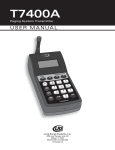
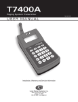
T7400 Guest Paging System By: Long Range Systems, Inc. 9855 Chartwell Dr., Dallas, TX 75243 1-800-437-4996 V6.21 and later User Manual With Installation, Warranty and Service Information Rev 3 November 2004 T7400 User Instr.doc WARRANTY Long Range Systems, Inc. warrants this product against any defects that are due to faulty material or workmanship for a two-year period after the original date of consumer purchase. This warranty does not include damage to the product resulting from accident, misuse or improper electrical connection. If this product should become defective within the warranty period, we will repair or replace with equivalent product, free of charge. We will return your product, transportation charges prepaid standard UPS Ground shipping mode, provided the product is shipped prepaid to: Long Range Systems, Inc., 9855 Chartwell, Dallas, TX 75243. No return or replacement can be received without prior authorization and the proper RMA# posted to the outside of the shipping container. This warranty gives you specific legal rights and you may also have rights that vary from state to state. Copyright © September 2001, Long Range Systems, Inc. All Rights Reserved This manual contains proprietary information of Long Range Systems, Inc. (LRS) and is intended for use only by its employees or customers. None of the material contained herein may be copied, reproduced, republished, downloaded, displayed, posted, or transmitted in any form or by any means, including but not limited to, electronic, mechanical, photocopying, recording, or otherwise without the prior written permission of LRS. Additional copies of this manual may be obtained by contacting LRS. Screen displays, keyboard layouts, hardware descriptions, or software are proprietary to LRS and are subject to copyright and other intellectual property rights of LRS and shall be treated in accordance with the previous paragraph. All attempts have been made to make the information in this document complete and accurate. LRS is not responsible for any direct or indirect damages or loss of business resulting from inaccuracies or omissions. Specifications and other information contained within this document are subject to change without notice. EU DECLARATION OF CONFORMITY We, Long Range Systems hereby declare under our sole responsibility that the T7400 paging transmitters and on-site pagers comply with the essential requirements in the European RE&TTE Directive 1999/5/EC of the European Parliament of the Council of 9 March 1999 on radio equipment and telecommunication terminal equipment and the mutual recognition of their conformity. The following standards were utilized: ETS 300 224: 1998 EN 301 489-2: 2002 EN61000-3-2: 1998 EN 61000-3-3: 1995 EN 60950: 1992 with A1, A2, & A3. Long Range Systems Messaging Page System Page 1 TABLE OF CONTENTS Long Range Systems.........................................................................................................................2 General Information ...........................................................................................................................2 Installation and Setup........................................................................................................................3 Hardware Provided.........................................................................................................................3 Installation Procedure....................................................................................................................3 Electrical Connections...................................................................................................................3 Keypad Description........................................................................................................................4 Initial Power Up and Time Set......................................................................................................4 Basic Paging Operation Guide.........................................................................................................5 Special Operational Procedures ....................................................................................................7 Wait List Function ...........................................................................................................................7 Theft-Deterrent Function................................................................................................................8 Locating Misplaced Pagers..........................................................................................................9 Tracking..........................................................................................................................................10 Feature Setup Procedures.............................................................................................................11 User’s Access Code....................................................................................................................11 Set Page Mode..............................................................................................................................11 Set to Page Staff or Guest Pagers.............................................................................................11 Setting Alarms...............................................................................................................................12 Set System Time/Date for Staff Pagers....................................................................................13 Create Additional Alpha Messages...........................................................................................13 Maintenance Functions...................................................................................................................14 Setting Start of POCSAG Paging................................................................................................14 Restaurant ID ................................................................................................................................14 Station ID........................................................................................................................................14 Adjust Transmit Power ................................................................................................................15 Range Test ....................................................................................................................................15 Dry Contact Operation..................................................................................................................15 Programming Pagers......................................................................................................................16 Programming Individual Rechargeable Pagers.....................................................................16 Program Battery Operated Pagers............................................................................................16 Set Pager Vibrator ON/OFF and Set Restaurant ID (Groups of Pagers)............................17 System Specifications ....................................................................................................................18 Transmitter.....................................................................................................................................18 Battery Powered Pagers..............................................................................................................18 Star Pager Adverteaser................................................................................................................18 Coaster Call...................................................................................................................................18 Troubleshooting................................................................................................................................19 Display shows Nothing ...............................................................................................................19 Pagers Don’t Receive Pages.....................................................................................................19 Battery Powered Pagers Don’t Receive Pages ......................................................................19 Service Questions and Answers..................................................................................................20 (800) 437-4996 Page 2 Page Master 7400 LONG RANGE SYSTEMS Long Range Systems On-Premise Paging Solutions are cutting edge products with first rate service to satisfy customer needs for years to come. Thorough familiarity with these instructions and procedures will ensure proper operation and maintenance of the system. Assistance is always available for any Long Range product by calling (800) 437-4996 Please don’t hesitate to call with any questions. NOTE: This guide should be kept readily available for managers and key staff. GENERAL INFORMATION The Page Master is an on-premise system used to increase throughput efficiency by alerting patrons of the availability of services. Additional staff paging capabilities can alert management of immediate needs. The pagers used with the system can vibrate, beep and display messages. The T7400 Paging System is used to page Coaster Call and AdverTeaser guest pagers, Star Pager and Alphanumeric staff pagers. Notice: Operation is subject to the following: This device may not cause interference This device will accept any interference including interference that may cause undesired operation of the unit. Notice: To reduce potential radio interference to other users, the antenna type and gain should be so chosen that the equivalent isotropically radiated power (EIRP) is not more than required for successful communication. STAFF PAGERS GUEST PAGERS Long Range Systems Messaging Page System Page 3 INSTALLATION AND SETUP Hardware Provided The system contains the transmitter keypad, an instruction booklet, an antenna, a strip of Velcro, rubber feet, and a 9-Vac power adapter. Notice: Operation is subject to the following: This device may not cause interference This device will accept any interference including interference that may cause undesired operation of the unit. Notice: To reduce potential radio interference to other users, the antenna type and gain should be so chosen that the equivalent isotropically radiated power (EIRP) is not more than required for successful communication. Installation Procedure The following is the basic installation procedure CAUTION: Do not mount the transmitter antenna near any large metal objects. 1. Unwrap all controller components. 2. Twist the antenna (about 3" long) onto silver connector on top of the controller. 3. Plug the power adapter into a standard 110V outlet and the barrel connector end into one of the side holes. 4. The systems are shipped set for the most general use. If you have specific changes, refer to the table of contents to locate the particular programming section. 5. Upon completion of setup make sure pagers are fully charged and/or have good batteries and are powered on. 6. You should perform a range test (page 15) to see if they can be paged in all locations of your facility. Electrical Connections The following diagram shows the electrical connections. 110 VAC ELECTRICAL SUPPLY 9 VAC POWER ADAPTER ANTENNA KEYPAD/TRANSMITTER (800) 437-4996 Page 4 Page Master 7400 Keypad Description Before you begin programming the keypad, read the following keypad descriptions. As the display changes, the keys may perform different functions. F Keys The F (function) keys are the first row of keys under the display. The F1, F2, F3, and F4 keys correspond to the bottom row of text in the keypad display window. Number Keys The number keys 1 through 0 are used to enter data such as the pager number. Setup Key The S e t u p key is used to enable menus when changing the transmitter programming. Mgr 1, Mgr 2, and Pager Keys The Mgr1, Mgr2, and Pager keys are used to page a manager pager. The Mgr1 and Mgr2 keys can be assigned to a specific pager. Staff (Pager) Key The Staff key is used to temporarily change the paging function to page Staff pagers. Clear Key The Clear key is used to clear the input when paging a pager or coaster and return to the Guest paging display or to restart an input when programming. Enter Key The Enter key is used to start the paging function, and to complete programming where required. Initial Power Up and Time Set 1. After the transmitter initializes the time set menu is shown. Enter the current time and press the <Enter> key. (NOTE: Pressing F1 (EXIT) bypasses this function and sets the time to 12:00am). 2. When the display asks for AM or PM press the F1 Key for AM or the F4 key for PM. (Note that AM is right above the F1 key and PM is right above the F4 key). The display changes to the guest menu with the time shown Long Range Systems Messaging Page System Page 5 BASIC PAGING OPERATION GUIDE The following are the most commonly used procedures for paging. Wake Up Coaster/Pagers Remove rechargeable guest or staff pagers from their charger and be sure any battery operated pagers are turned on. Page Guest Pagers Enter the number you assigned to the guest at handout and press Enter. Note: be sure to put pagers back on charge when returned. Page Individual Staff Pagers: 1. Press the Staff button. 2. Enter the pager number and press Enter. 3. At the Select Page Mode screen. Press V1, V2, or V3 to send 1, 2, or 3 vibrations to the pager. Enter a numeric message for battery powered pagers and press. Select an alpha message for battery powered pagers and press Enter (Note a list of canned messages is shown on page 5.) Page Manager Pagers If Manager Pagers are Assigned, MGR1 and MGR2 page those assigned pagers. 1. Press the MGR1 or MGR2 button 2. At the Select Page Mode screen. Press V1, V2, or V3 to send 1, 2, or 3 vibrations to the pager. Enter a numeric message for battery powered pagers and press. Select an alpha message for battery powered pagers and press Enter (Note a list of canned messages is shown on page 5.). Page All Staff (if all battery operated staff pagers need to be called at once) 1. Press Staff. 2. Press 9 1 1 then Enter. 3. At MSG enter any desired message. 4. Press Enter. Page All Call (if all guest and rechargeeable staff pagers need to be called at once) Press 000 then Enter. At Page All? press YES (F1). Pre-canned or Special Alpha-Messages When prompted by the T74-series transmitter for a message, enter the code and a numeric extension before pressing the Enter key (refer to the following chart). Example: To send a message to call extension 123, enter the code 006123. The pager will show CALL EXT 123. EXTENSION # 006 MESSAGE (800) 437-4996 Page 6 Page Master 7400 Note: These messages are built into the transmitter when using Alpha pagers. Additional messages can be programmed into the keypad (see Feature Setup procedures page 13). Pre Loaded Messages Code 000 001 002 003 004 005 006 007 008 009 010 011 012 013 014 015 016 017 018 019 020 021 022 023 024 025 Message Phone Call Sale Call Manager Customer Room Visitor call Ext MTG Room Lane Isle Void Stamps Change Station Machine operator Emergency XX Minutes Tee Pro Shop Starter Service Drive Showroom Parked Call Voice Mail Dressing RM Code 026 027 028 029 030 031 032 033 034 035 036 037 038 039 040 041 042 043 044 045 046 047 048 049 050 051 Message Price check Department Cashier Office Table Winner Pickup Dock You have mail Table ready No Special Hole Kitchen Bar Door Survey T-nnn Q-xx Break nnnn Fire Unit Window Nurse Register Owner Check Drink Long Range Systems Code 052 053 054 055 056 057 058 059 060 061 062 063 064 065 066 067 068 069 070 071 072 073 074 075 076 Message Food Service Seat Check Lobby Help Restrm Valet Car Bus Bay Lo batt error Exit Fax Host Space Location Nursery Teller Office Buffet Diap chng Child cry To nursery Messaging Page System Page 7 SPECIAL OPERATIONAL PROCEDURES The procedures in this section are additions to the basic paging functions. descriptions are listed in the order they appear on the menus. The Wait List Function This feature allows the host to accurately inform guests as to their wait time. In order to get accurate readings, the keypad must know when coasters are handed out to the guests. This feature does not require an authorization code. Basic Concept Wait time is determined by the number of coasters handed out multiplied by the Wait/Party setting. Example, • The wait per party default is 2 minutes • After coasters are given to 10 parties the keypad would indicate a wait time of 20 minutes. • The Wait/Party is programmable so if you feel you are turning tables faster than 2 minutes, you can enter your new value into the Wait/Party setting and the keypad will begin using the new value. Enabling, Clearing, and Adjusting the Function After some use the wait time may be adjusted to fit the needs of your restaurant. 1. Press SETUP 1:Clear Wait List 2:Wait ON/OFF 2. Press “1” for “Set Wait List” 3:Set Wait/Party 3. At the Wait List Option menu (at right) press: MORE HELP EXIT • 1 to clear the wait list for a new day. • 2 to turn wait list ON or OFF using the F1 (ON) and F2 (OFF). • 3 to set the average wait time expected for each party. Using the Wait List function Note: before each shift, always clear the wait time. The wait time is not available because coasters have not yet been given out. To use the feature: 1. Clear the previous night’s wait list (see procedure above). 2. Be sure the wait list function is enabled (When Wait Timer is on, “Wait Time = N/A” is displayed under the guest prompt). 3. When the coaster/pager is given out, enter the coaster/pager number then press the HANDOUT (F1) button. This automatically adds the amount of wait time set to the display for the host to use. 4. When the Guest’s table is available enter the pager number followed by Enter. This automatically reduces the wait time on the display. (800) 437-4996 Page 8 Page Master 7400 Theft-Deterrent Function Theft deterrent is used to alert staff and guests that they are leaving the premises while still carrying the pager. When used, the transmitter sends a signal that the coaster/pager must receive or it will alarm. If the pager is taken out of range (off premises) and can not receive this signal it will emit an annoying beep. A "T" in the upper left corner of the display indicates the Theft-Deterrent Mode is ON. The factory default is OFF. To turn Theft-Deterrent Mode ON or OFF: Notice: Operation is subject to the following: This device may not cause interference This device will accept any interference including interference that may cause undesired operation of the unit. Notice: To reduce potential radio interference to other users, the antenna type and gain should be so chosen that the equivalent isotropically radiated power (EIRP) is not more than required for successful communication. IN RANGE AREA PAGERS OPERATE NORMALLY OUT OF RANGE AREA PAGERS ALARM 1. Press SETUP to enable the function menu. 2. Press 3 to select Theft Deterrent. 3. Press F1 (ON), F2 (OFF), F3 for HELP and “F4” for Exit. Long Range Systems Messaging Page System Page 9 Locating Misplaced Pagers Two location modes are available for finding lost or misplaced pagers/coasters. Auto Locate automatically searches at a preset time, Run Locate searches on demand. Auto Locate Auto Locate sends out a signal to ALL coasters/pagers at a preset time. For example, If you close at 11:30PM, the keypad can automatically send out a signal at 12:30AM that will cause all missing coasters to start beeping. Then the staff will be able to locate the beeping guest pagers. To program Auto Locate; 1. Press SETUP 2. Press “MORE” (F1) until asked for the authorization code. 3. Type 5-6-7-8-9 4. Repeatedly press F1 until you see “Prog Auto Loc on the menu. 5. Now press the number that corresponds to the feature. 6. The Screen will show if AUTO Locate is on or off Press F2 to turn the function OFF and the unit returns to the guest menu. Press F1 to turn the function ON 7. If turning the function ON: Press F4 (EXIT). The display asks for the time to start the function. Enter the time and press the ENTER key. Press F1 (AM) or F4 (PM) and the unit returns to the guest menu. Run Locate Run Locate sends out a signal to ALL coasters/pagers when required. This Mode causes ALL coasters to Beep or Flash. This mode is useful when you are closed and would like to locate any misplaced coasters around your restaurant. To locate ALL coasters: 1. Press SETUP 2. Press “MORE” (F1) until you are asked for the authorization code. 3. Now type 5-6-7-8-9 4. Repeatedly press F1 until you see “Run LOCATE on the menu. 5. Now press the number that corresponds to the feature. The display will show that the MODE of the coaster/pager is either flash or beep. 6. Press: F1 (GO) to start locating (if the mode is already set). F2 (MODE) to set the unit to beep (1) or flash (2) then press F1 (GO) to start locating. (800) 437-4996 Page 10 Page Master 7400 Tracking This lets the host see which coaster or pager has been paged and keeps paging the user until it is returned and that number is cleared. Caution: When in this mode, the keypad constantly tries to re-page coasters. The number MUST be cleared when the coaster is returned or you will have angry guests with coasters that keep flashing To turn Tracking on (or off): 1. Press SETUP 2. Press “MORE” (F1) until asked for the authorization code. 3. Type 5-6-7-8-9 4. Repeatedly press F 1 until you see “Prog Tracking on the menu. 5. Press F1 (ON) (or F2 (OFF)) 12:34:56 pm Pager #: --Pgr Pgr 99 82 92 MORE PAGERS IN THE QUEUE To Use Tracking Page the coaster or pager in the normal manner. The pager number will appear at the bottom of the screen As long as the number is at the bottom of the screen the pager is being paged. Clear the Page by pressing the F1, F2 or F3 key under the pager number shown on the display when the pager is returned, If more than 3 pagers are in the queue the MORE will be shown at the right of the display. Press the F4 (MORE) key to see the rest of the list. PAGER MENU F1 F2 PRESS TO CANCEL PAGER 99 PRESS TO CANCEL COASTER 82 Long Range Systems PRESS TO CANCEL PAGER 92 PRESS TO SCROLL THROUGH THE PAGE LIST F3 F4 Messaging Page System Page 11 FEATURE SETUP PROCEDURES After using the system a while it may be desirable to change some of the default settings to be more attuned to your use. The following procedures will help you find the perfect settings for your place. User’s Access Code Many of the functions that adjust paging preferences are protected by an access code. • To reduce tampering with critical settings the keypad is password protected • The access code 56789 allows you to enter most restricted programming screens. • Press F4 at any menu to return to the Guest menu. Set Page Mode This allows you to program how you would like the coasters and manager pagers to be paged. You can have the coasters flash, beep, glow, flash and beep, etc. All page modes are programmable by the staff and do not require an authorization code. To set the modes: 1. Press SETUP. 2. Press 2 (Set Page Mode). 3. Select 1 (Guest Pager) or 2 (Manager Pager) Guest Select 1 (non Voice mode) then select: Flash (1) to set the amount of time the pager flashes before shutting off. (1sec, 30-sec, 5-min, and simultaneous beep and flash). Default is 5 minutes. Beep Only (2) to set the how many times the pager will beep before shutting off (either three beeps or 5 minutes). Glow (3) to set the amount of time the unit will glow before shutting off (either 15 Glow cycles or 5 minutes of glow cycles). Manager Select: Vibrate (1) to set the number of vibrations for the pager. Default is 3. Beep (2) to set the number of times the pager will beep before shutting off (3, times, 5-minutes, Look Down). Both (3) to set the number of times the pager will beep and vibrate glow before shutting off. Set to Page Staff or Guest Pagers In cases where the unit will be always paging staff pagers, the keypad can be set to default to page either Guest or Staff pagers. Factory default is Guest: 1. Press SETUP. 2. Press “MORE” (F1) until asked for the authorization code. 3. Type 5-6-7-8-9 (800) 437-4996 Page 12 Page Master 7400 4. Repeatedly press F1 until you see “Default Mode on the menu. 5. Now press the number that corresponds to the feature. 6. Press F1 (Guest) or F4 (Pager). Setting Alarms This function is used to set the transmitter to page individual or all pagers at a specific time or on a timed interval. The transmitter can send 3 different time alarms or periodic alarms. Alarms may be set to page a specific pager (or all pagers) at a specific time every day 1. Press Setup. 2. Press “MORE” (F1) until asked for the authorization code. 3. Type 5-6-7-8-9 4. Repeatedly press F1 until you see “Set ALARMS on the menu. 5. Press the associated number key. 6. From the Pick Alarm menu, select the number of the alarm to set (0 through 9). 7. The Alarm Display screen shows the status of the selected alarm. Select Change (F1) to enable/disable or modify the alarm. Note: If the alarm is already enabled as an interval alarm Press YES (F1) to reset the timer and return to the paging menu Press NO (F4) to continue to the ON/OFF menu 8. At Turn ON or OFF menu select ON (F1) to enable the alarm or OFF (F2) to disable the alarm. 9. At Set Pager Number menu: 10. Press either enter the number of the pager to be alarmed followed by Enter or Press KEEP (F1) to use the existing number. Note: Entering pager number 911 will page all pagers 11. At the Msg: prompt enter the message to send followed by Enter: (a list of canned messages is shown on page 5) Interval Alarms are alarms that re-page a staff pager at regular intervals 1. At the Interval Alarm?, select YES (F1) 2. Enter the desired time interval in hours and minutes (HH:MM) and Press Enter. Transmitter returns to the paging menu. Timed Alarms are alarms that re-page a staff pager at a particular time every day. 1. At the Interval Alarm?, select NO (F4) 2. At the Set Start Time menu enter the time for the alarm followed by Enter: 3. Select AM (F1) or PM (F4). Transmitter returns to the paging menu. Long Range Systems Messaging Page System Page 13 Set System Time/Date for Staff Pagers Time is normally reset to 12:00 each time batteries are replaced. The time/date may be reset at the individual pagers, but all pagers in use may be synchronized to the transmitter. To prepare and send time/date information to Battery Operated Alpha staff pagers (re-programmable pagers available in 2005 only). Set the Date 1. Press SETUP to enable the function menu. 2. Press F1 (More) until the unit shows 1:Set Time/Date. 3. Press 1 to select Set Time/Date. 4. Press F1 (Date). 5. Enter the date in MO/DA/YR (e.g. Mar 21, 2004 = 03/21/04). 6. Press Enter. Set the Time 7. Press F2 (Time). 8. Enter the time in hours and minutes. 9. Press Enter. 10. Press F1 (for AM) or F2 (for PM). Send the Time and Date to the Pagers 11. Be sure the battery powered pagers are on. 12. Press the number 1 (Send to Pager) and the pagers will update. Create Additional Alpha Messages This function is used to create and store custom Alpha messages (Alpha mode only). These messages will be numbered 077 through 099. Once created they are paged the same as the standard canned messages. To create the messages: 1. Press Setup. 2. Press MORE (F1) until asked for the authorization code. 3. Type 5-6-7-8-9 4. Repeatedly press F1 until you see Canned Msgs on the menu. 5 Press UP (F2) or DN (F3) to locate a message to replace or add a message in an unused slot. 5. Press EDIT (F1) then NEW (F2) to enter the message. 6. Enter the desired message (up to 32 characters). 7. Press EXIT (F1) to return to the canned message menu. 8. Press EXIT (F1) to return to the Setup menu. (800) 437-4996 Page 14 Page Master 7400 MAINTENANCE FUNCTIONS The following features are not normally adjusted unless directed by LRS. Setting Start of POCSAG Paging This function is used to set the crossover point for staff pagers where Rechargeable numbers end and Battery Operated (POCSAG) pager numbers begin (default is 50). To change the crossover point: 1. Press Setup. 2. Press “MORE” (F1) until asked for the authorization code. 3. Type 5-6-7-8-9 4. Repeatedly press F1 until you see “POCSAG Pager Start” on the menu. 5. Press the associated number key. 6. Enter the starting number. This number is The highest numbered rechargeable + 1 The lowest numbered battery operated pager. 7. Press ENTER. Restaurant ID The restaurant ID is used to prevent interference when more than one paging system is in use in a small geographical area (e.g., next door). USE ONLY AT THE DIRECTION OF LRS, To set the ID 1. Press Setup. 2. Press “MORE” (F1) until you are asked for the authorization code. 3. Now type 5-6-7-8-9 4. Press the MORE (F1) key the display shows “2: Set Rest ID”. 5. Press the “2” key. 6. When the display shows Rest ID = X (X is 0, 1, 2, or 3) press the desired number. 7. Press the Enter key. 8. When Finished, Press OK (F1). 9. After the transmitter ID is changed, program the pagers to match. Station ID Station ID is often confused with Restaurant ID. This function is used where more than one station of the same establishment may be paging staff pagers. The indictors on the pager will show this code. To set a different station number: 1. Press SETUP 2. Press “MORE” (F1) until you are asked for the authorization code. 3. Now type 5-6-7-8-9. 4. Repeatedly press F1 until you see “Prgm Station ID on the menu. 5. Now press the number that corresponds to the feature. The display will show the current station number for the pager to display (default is 1). 6. Press a number to use (0 – 9). Long Range Systems Messaging Page System Page 15 7. Press F1 (OK) to change the code or F2 (Exit) to return without change. Adjust Transmit Power The range may be increased or decreased from the keypad. The power levels are 1 through 5. Find a power level using Range Test that best suits your restaurant and leave it that way. Default from the factory is power level 3. To set the power level: 1. Press SETUP. 2. Press “MORE” (F1) until you are asked for the authorization code. 3. Type 5-6-7-8-9. 4. Repeatedly press F1 until you see “Program TX Pwr on the menu. 5. Now press the number that corresponds to the feature. 6. Set the required power level (from 1 through 4). 7. Press <Enter>. 8. Press F1 (OK). Range Test This allows you to see where you can and cannot be paged. Although the range may vary slightly during busy times, this allows you to get a rough idea of where guests can roam. DO NOT PERFORM A RANGE TEST WHEN GUESTS HAVE PAGERS BECAUSE THEY WILL FLASH ALL AT ONCE. To begin Range Test: 1. Press SETUP. 2. Press MORE (F1) 2 times. 3. When asked for the authorization code enter 5-6-7-8-9. 4. Continue pressing MORE (F1) until you see Run Range Test. 5. Press the corresponding number for Range Test to begin. 6. Take 2 or 3 charged coasters and begin walking around your restaurant. You should be seeing the coasters flashing about once every 3-4 seconds. 7. When you reach the point where the coaster does not flash consistently, this is your maximum range. Dry Contact Operation The dry contact input is located next to the transmitter antenna. To enable/disable: 1. Press SETUP. 2. Press F1 (more) until asked for the authorization code. 3. Enter 5-6-7-8-9 4. Repeatedly press F1 to find and select Dry Contact. 5. When the display shows the sensor is ON or OFF, press: F1 (ON) to enable the feature. F2 (OFF) to disable the feature. 6. For Contact Mode, select F1 (normally OPEN contacts) or F4 (normally CLOSED contacts). NOTE: If using a NC contact insert the closed contact in the jack before programming as the unit automatically goes into the paging mode. (800) 437-4996 Page 16 Page Master 7400 7. Enter the ALPHA pager number to be paged. 8. Pres EDIT to create a message for the selected pager. PROGRAMMING PAGERS Programming Individual Rechargeable Pagers Pager numbering and modes is used when renumbering and setting up individual pagers. Note: Rechargeable pagers can have their restaurant IDs changed or their vibrators turned on/off as a group. 1. Acquire a programming authorization code from LRS. 2. Determine the necessary Restaurant ID, then set the transmitter to that ID. 3. Press Setup. 4. Press “MORE” (F1) until you are asked for the authorization code. 5. Now type 5-6-7-8-9 6. Press the MORE (F1) key until the display shows “3:Prog. Pgr. ID”. 7. Press the “3” key. 8. At the Menu, select Guest or Staff (the type of pager you are re-programming. Guest pagers are Coasters and AdverTeaser Paddle pagers. Staff pagers are Star pagers and the Battery operated staff pagers. 9. Enter the authorization code For Guest pagers use the code acquired from LRS. For Staff pagers use 1 2 3 7 6. 10. Place all the rechargeable pagers to be programmed on one charger and leave the second charger empty. Pagers may be replaced into the same slot in the charger. 11. For guest pagers, select Vibe ON or Vibe OFF. 12. At Enter ID --- enter the number you wish the pager to be (e.g., 41). 13. Press Enter. 14. Remove the pager from the charger. When the flashing stops, press <Enter>. 15. The pager will slowly brighten and dim to off to indicate it is being programmed. 16. When it is finished put the pager on the second charging base or the pager back into its slot. 17. Repeat for the remaining pagers to be programmed. 18. When finished remove all of the reprogrammed units from the charger and page each one. Re program any pagers that do not page. 19. When Finished, Press EXIT (F1). Program Battery Operated Pagers This procedure is repeated for each pager being programmed (re-programmable battery operated pagers are not available until after January 2005). Long Range Systems Messaging Page System Page 17 1. 2. 3. 4. Turn all of the pagers OFF. At the Menu, select Staff Enter the access code 1 2 3 7 6 Select Alpha, Numeric or Vibe Only. (Note: re-programmable Alpha pagers will be available in 2005). 5. At Enter ID --- enter the number for the pager to be programmed. 6. Press Enter. 7. Turn on the pager. 8. When the vibrating (and or beeping) stops, press Enter again. 9. The pager will double beep three times to indicate it is being programmed. When it is finished turn the pager OFF. 10. Repeat steps for the remaining pagers. 11. When finished turn all of the pagers on and page each one. Reprogram any pagers that do not page. 12. When Finished, Press EXIT (F1). Set Pager Vibrator ON/OFF and Set Restaurant ID (Groups of Pagers). Rechargeable pagers can have their restaurant IDs changed or their vibrators turned on as a group. Note: Programming Individual Pagers process is required to renumber and set up individual pagers. 1. Be sure all the pagers are in the charger. 2. Press Setup. 3. Press “MORE” (F1) until you are asked for the authorization code. 4. Now type 5-6-7-8-9 5. Press the MORE (F1) key the display shows “2:Prog. Vib”. 6. Press the “2” key. 7. Remove several (about 10) pagers from their charger and quickly separate them. 8. As soon as the pagers stop vibrating and flashing, press the ON (F1) or OFF (F2) button. 9. The pagers will slowly brighten and dim to off to indicate they are being programmed. When finished put them on the second charging base. 10. Repeat for any remaining pagers. (800) 437-4996 Page 18 Page Master 7400 SYSTEM SPECIFICATIONS Notice: Operation is subject to the following: This device may not cause interference This device will accept any interference including interference that may cause undesired operation of the unit. Notice: To reduce potential radio interference to other users, the antenna type and gain should be so chosen that the equivalent isotropically radiated power (EIRP) is not more than required for successful communication. Transmitter Required voltage: One 110V outlet for the pager keypad. Operating Frequency: 467.750MHz Radiated Power <4900 micro-volts/meter Operating Range: Dependent upon pagers used Battery Powered Pagers Required voltage: One AAA Alkaline battery for the pager. Star Pager Adverteaser Required voltage: (1) 110V outlets for pager chargers Batteries: Nickel Metal Hydride (NiMH). Rechargeable. Lifetime of Batteries: Approximately 3-5 years Number of pagers per charger: 5. The maximum number of pagers that can be charged by a 9V power supply is 30 (6 chargers). If you have more than 30 pagers, you will require the high current power supply that can charge up to 80 pagers on a single outlet. Battery life of pager: Approximately 12 - 48 hours (depends on how often they are paged). Recharge time: 24 hours minimum from completely “dead”. Coaster Call Required voltage: 1-110V outlet for pager chargers Batteries: Nickel Metal Hydride (NiMH). Rechargeable. Lifetime of Batteries: Approximately 3-5 years Number of pagers per charger: 15. There can be 60 pagers (max.) or 4 chargers per 9V power supply. If you have more than 60 pagers, you will require additional power supplies. Battery life of pager: Approximately 48 hours (depends on how often they are paged). Recharge time: 24 hours minimum from completely “dead”. Long Range Systems Messaging Page System Page 19 TROUBLESHOOTING Display shows Nothing Be sure power supply is plugged in. If yes – Be sure power supply is good (substitute). – Be sure the wall circuit is on. – Unplug and re-plug a few times to be sure the unit doesn’t need a reset. If no – plug it in Remedy If power supply is good call LRS to get a new transmitter If power supply is bad call LRS to get a new power supply. Pagers Don’t Receive Pages Be sure pagers are ON, Awake, Charged or have Good Batteries Try paging more than one pager to be sure it’s not a faulty pager. Do a System Reset Check the Restaurant ID Use the ID finder function. 1. Remove 2 or 3 pagers or coasters from the charger or turn on some battery powered pagers. 2. Press Setup. 3. Press “MORE” (F1) until asked for the authorization code. 4. Now type 5-6-7-8-9 5. Press the MORE (F1) key the display shows “ID Finder”. 6. Press the “1” key. 7. Press Begin (F1) and the unit searches all of the ID = 0 codes. 8. When it has paged all of the codes it asks “Did Your Pager Work?” If your pagers paged, press YES (F1) and the unit will be set to this ID. If your pagers didn’t page, press NO (F4) twice and the unit will try the next ID. If the unit cycles back to ID 0 without the pagers responding, call LRS. Battery Powered Pagers Don’t Receive Pages 1. Be sure the pager is turned on and that the battery is good 2. If pagers do not turn on, replace battery and retry. 3. If pagers do turn on, and still do not receive page, check transmitter. (800) 437-4996 Page 20 Page Master 7400 SERVICE QUESTIONS AND ANSWERS Should your paging system ever fail or should you need additional paging supplies, call Long Range Systems at (800) 437-4996 Monday through Friday 8:30 am to 5:00 pm Central Time. For weekend or night emergencies: Long Range Systems has 24/7 live technical support available Please keep in mind that options are limited over the weekend. Long Range Systems