1
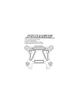
Bulldog III
U S E R M A N UA L
I n s t a l l a t i o n , Wa r r a n t y a n d S e r v i c e I n f o r m a t i o n
Long Range Systems UK Ltd | Link House | Leek Road | Milton | Stoke on Trent | Staffordshire | ST2 7AH | 01782 537000
www.lrspagers.co.uk | www.pagers.co | www.hospitalpagers.co.uk
Table Of Contents
Long Rang Systems . . . . . . . . . . . . . . . . . . . . . . . . . . . . . . . . . . . . . . . . . . . . . .
2
General Information
.............................................
2
General . . . . . . . . . . . . . . . . . . . . . . . . . . . . . . . . . . . . . . . . . . . . . . . . . . . . . . . . . . . . .
2
Pager Alert Notification . . . . . . . . . . . . . . . . . . . . . . . . . . . . . . . . . . . . . . . . . . . . . . . .
2
Installation . . . . . . . . . . . . . . . . . . . . . . . . . . . . . . . . . . . . . . . . . . . . . . . . . . . . .
3
Optional Tools . . . . . . . . . . . . . . . . . . . . . . . . . . . . . . . . . . . . . . . . . . . . . . . . . . . . . . .
3
Hardware Provided . . . . . . . . . . . . . . . . . . . . . . . . . . . . . . . . . . . . . . . . . . . . . . . . . . .
3
Setup . . . . . . . . . . . . . . . . . . . . . . . . . . . . . . . . . . . . . . . . . . . . . . . . . . . . . . . . . . . . . . .
4
Mounting . . . . . . . . . . . . . . . . . . . . . . . . . . . . . . . . . . . . . . . . . . . . . . . . . . . . . . . . . . .
5
Range Tuning . . . . . . . . . . . . . . . . . . . . . . . . . . . . . . . . . . . . . . . . . . . . . . . . . . . . . . . .
6
Troubleshooting . . . . . . . . . . . . . . . . . . . . . . . . . . . . . . . . . . . . . . . . . . . . . . . . .
7
Pagers ate not being set off? . . . . . . . . . . . . . . . . . . . . . . . . . . . . . . . . . . . . . . . . . . . .
7
What to do if the System Malfunctions . . . . . . . . . . . . . . . . . . . . . . . . . . . . . . .
7
System Repair After the Warranty Expires? . . . . . . . . . . . . . . . . . . . . . . . . . . . . . . .
7
Ordering Additional Equipment . . . . . . . . . . . . . . . . . . . . . . . . . . . . . . . . . . . . . . . . .
7
Warranty . . . . . . . . . . . . . . . . . . . . . . . . . . . . . . . . . . . . . . . . . . . . . . . . . . . . . . .
8
Long Range Systems
1
Bulldog User Manual
LONG RANGE SYSTEMS
Long Range Systems On-Premise Paging Solutions are cutting edge products with first rate service to satisfy customer needs for years to come. Thorough familiarity with these instructions and procedures will ensure proper operation and maintenance of the system. Assistance is always available for any Long Range
product by calling
(800) 437-4996 or (214) 553-5308
Please do not hesitate to call with any questions.
NOTE: This guide should be kept readily available for managers and key staff.
GENERAL INFORMATION
General
The Bulldog is a device designed to prevent the theft of pagers from the premises. When a pager comes
within the set range of the Bulldog, the pager will vibrate and/or beep to alert the patron that they still have
the pager and need to return it.
When mounting the Bulldog, it is recommended to select a location near a standard 110-Vac electrical outlet.
Pager Alert Notification
Staff Pagers:
Staff pagers require the second switch on the 3 position switch to be set to the ON position (see page 5)
• RX-SP5 – 1-Line Rechargeable Alphanumeric pager: Beeps, display shows “Please return
pager.”
• RX-E467 – 4-Line Battery Operated Alphanumeric pager: Beeps, display shows “Please return
pager.”
• RX-SP4 – Rechargeable Staff pager: Lights flash, pager vibrates.
Guest Pagers:
Guest pagers require the first switch on the 3 position switch to be set to ON position (see page 5)
• RX-CB4, RX-CC4, RX-CG4, RX-CS4, RX-CS4NP – Coasters: Lights flash, pager vibrates or beeps.
• RX-LP – Lobster Calls: Lights flash, pager vibrates or beeps.
• RX-AT4 – Adverteaser (Paddle Pager): Lights flash, pager vibrates or beeps.
• RX-PZ4 – Pizza Pager: Lights flash, pager vibrates or beeps.
Alpha Coasters:
Alpha Coasters need to be in STAFF mode, setting the second switch on the 3 position switch to the ON position (see page 5)
• RX-AC-BL, RX-AC-SM – Alpha Coaster: Display shows “Please return pager”, pager beeps.
Long Range Systems
2
Bulldog User Manual
INSTALLATION
Optional Tools
Slot or Phillips head screwdriver with a 2.5mm tip.
Hardware Provided
The system contains the Bulldog, an instruction booklet, an antenna, strip of Velcro, tuning stick, 4 antenna
mounts, and a 15-Vac power adapter.
Range Tuner
15-Vac
Connection
Antenna
Long Range Systems
3
Bulldog User Manual
Setup
1. Set the DIP Switches, located on bottom of the Bulldog, to the desired settings.
ON C&K SD03
1
2
ON
C & K SD04
1
3
2
3
4
3 – Position Switch Settings
1 = GUEST PAGERS
2 = STAFF PAGERS
3 = MODE (ON = BEEP, OFF = VIBE)
–––––––––––––––––––––
2. Set the 3-position switch to set pager type and mode.
• To Alert Guest Pagers – Set 1 to ON and 2 to OFF.
• To Alert Staff Pagers – Set 1 to OFF and 2 to ON.
Notes: For proper functioning, set the Bulldog to alert either Staff or Guest
• 3: Set to ON to alert using beeps. Set to OFF to alert using the vibrations.
3. Set the 4-postion switch to the ID number of the pagers. Use the following table to set the switch
positions:
Switch
ID
ID
0
1
2
3
4
5
6
7
8
9
10
11
12
13
14
15
1
2
3
4
OFF
OFF
OFF
OFF
OFF
ON
OFF
OFF
ON
OFF
ON
ON
OFF
ON
ON
OFF
ON
ON
OFF
ON
OFF
OFF
ON
ON
ON
ON
OFF
OFF
OFF
OFF
ON
OFF
ON
OFF
ON
ON
OFF
OFF
OFF
ON
ON
OFF
ON
ON
OFF
OFF
ON
ON
ON
ON
OFF
OFF
OFF
OFF
OFF
OFF
ON
ON
ON
ON
ON
ON
ON
ON
Example: To set for ID = 0, set all 4-position switches to the OFF (down) position.
Long Range Systems
4
Bulldog User Manual
4. As required, attach the self-adhesive Velcro to the Bulldog.
Mounting
Notes:
• This device is not an outdoor unit.
• Mounting the Bulldog immediately next to a metal door frame will reduce the transmitting
range. Allow a few extra inches of separation between the frame and the Bulldog with antenna.
• If possible, mount antenna on exterior of door frame (opposite of the dining area.)
1. Place the second half of Velcro on pre-determined location. Mount the Bulldog to the wall.
2. Connect Power.
3. Insert the antenna plug into the Bulldog.
4. Run the antenna around the door frame. Use the provided antenna mounts to secure the antenna.
Bulldog
Antenna Wire
Around Door Frame
Power
CONDOR
(408)745-7141
CLASS 2 TRANSFORMER
INPUT: AC 12OV 60Hz 19w
OUTPUT: AC 9V 1800mA
P/N: A91A8
UL
RoHS
LISTED
C
UL
MODEL: 48A -9- 1800
EIA 363 0635 S
MADE IN CHINA
Long Range Systems
5
Bulldog User Manual
Range Tuning
The Bulldog has a tunable range for setting off pagers. The Range Tuner, located on the front of the Bulldog,
can be adjusted to set the range as desired. Default setting when shipped is at maximum.
To adjust the range, have a charger, 1 fully charged pager, and a tuning stick available (Notes: keep the
charger at least 30 feet away from the Bulldog), then:
1. Reset the pager by removing it from the charger. After the pager finishes blinking/vibrating, approach the Bulldog at a normal walking pace. When the pager begins to constantly vibrate and
or beep, this is the current range of the Bulldog.
2. Place the pager on charger to stop the vibrating/beeping.
3. Use the tuning stick to adjust the Range Tuner:
• Clockwise to increase the range
• Counter-clockwise to decrease the range.
Counter-Clockwise
Clockwise
4. Repeat steps 1 through 3 until desired range is set.
Notes:
• The Bulldog has less range with moving pagers than stationary pagers. Example: Customer’s
pager sitting at Table B may go off even though a person walking would be set off only a few
feet from the door.
• When mounting and setting the Range of the Bulldog, keep in mind the location of where patrons will sit or wait. If the Bulldog is located near eating tables or a waiting area, adjust the
range or position so the customers are not getting unneeded pages.
Maximum Range
B
Adjusted Range
B
A
C
New Range
of Bulldog
Range of Bulldog
Guest Seating
Guest Seating
D
Long Range Systems
A
C
D
6
Bulldog User Manual
TROUBLESHOOTING
Pagers are not being set off?
1. Be sure Bulldog power is plugged in and LEDs around Range Tuner are on.
2. Be sure antenna is plugged in.
3. Be sure range is set.
4. Check System ID of pagers (check using LRS transmitter.)
5. Check ID set for the 4-position switch, reference table on page 5.
6. Check if 3-Postion switch is set for using Guest or Server pagers. The system will operate in either Guest or Server mode; do not operate both modes simultaneously.
WHAT TO DO IF THE SYSTEM MALFUNCTIONS
Should your system ever fail to function properly call Long Range Systems at (800) 437-4996 Monday through
Friday 8:30 AM to 5:00 PM Central Time.
• After hours, please leave a message on the technical support line.
• After hours and on weekends, LRS technicians are paged whenever a message is left on the
tech support line.
• Long Range will return the call as soon as possible.
• Please keep in mind that options are limited over the weekend.
System Repair After the Warranty Expires?
We suggest calling Long Range Systems before sending a non-warranty item in for repair.
** Out of warranty items will be repaired and sent back C.O.D.
Ordering Additional Equipment
Call Long Range Systems @ (800) 437-4996 for an order form and ordering instructions. Fax the Order sheet
back to Long Range Systems at (214) 221-0160. No cover sheet needed.
Long Range Systems
7
Bulldog User Manual
Warranty
Long Range Systems, Inc. warrants this product against any defects that are due to faulty material or workmanship for
a two-year period after the original date of consumer purchase. This warranty does not include damage to the product
resulting from accident, misuse or improper electrical connection. If this product should become defective within the warranty period, we will repair or replace it with an equivalent product, free of charge. LRS will return your product via UPS
ground shipping. All warranty claims must be initiated through our customer service department.
This manual contains proprietary information of Long Range Systems, Inc. (LRS) and is intended for use only by its employees or customers. None of the material contained herein may be copied, reproduced, republished, downloaded, displayed, posted, or transmitted in any form or by any means, including but not limited to, electronic, mechanical, photocopying, recording, or otherwise without
the prior written permission of LRS. Additional copies of this manual may be obtained by contacting LRS.
Screen displays, keyboard layouts, hardware descriptions, or software are proprietary to LRS and are subject to copyright and other intellectual property rights of LRS and shall be treated in accordance with the previous paragraph.
All attempts have been made to make the information in this document complete and accurate. LRS is not responsible for any direct
or indirect damages or loss of business resulting from inaccuracies or omissions. Specifications and other information contained within
this document are subject to change without notice.
Long Range Systems, Inc. reserves the right to make changes without further notice to any products herein. LRS, Inc. makes no warranty, representation or guarantee regarding the suitability of its products for any particular purpose, nor does LRS, Inc. assume any liability arising out of the application or use of any product or circuit, and specifically disclaims any and all liability, including without
limitation consequential or incidental damages. “Typical” parameters that may be provided in LRS, Inc. data sheets and/or specifications can and do vary in different applications and actual performance may vary over time. All operating parameters, including “Typicals”, must be validated for each customer application by customer’s technical experts. LRS, Inc. products are not designed, intended,
or authorized for use as components in systems intended to support or sustain life, or for any other application in which the failure of
the LRS, Inc. product could create a situation where personal injury or death may occur. Should Buyer purchase or use LRS, Inc. products for any such unintended or unauthorized application, Buyer shall indemnify and hold LRS, Inc. and its officers, employees, subsidiaries, affiliates, and distributors harmless against all claims, costs, damages, and expenses, and reasonable attorney fees arising out
of, directly or indirectly, any claim of personal injury or death associated with such unintended or unauthorized use, even if such claim
alleges that LRS, Inc. was negligent regarding the design or manufacture of the part, device or system.
EU DECLARATION OF CONFORMITY
We, Long Range Systems hereby declare under our sole responsibility that the Bulldog paging transmitters and on-site
pagers comply with the essential requirements in the European RE&TTE Directive 1999/5/EC of the European Parliament
of the Council of 9 March 1999 on radio equipment and telecommunication terminal equipment and the mutual recognition of their conformity. The following standards were utilized:
ETS 300 224: 1998
EN 301 489-2: 2002
EN61000-3-2: 1998
EN 61000-3-3: 1995
EN 60950: 1992 with A1, A2, & A3
XU-0011 030410
Long Range Systems
8
Bulldog User Manual
Long Range Systems UK Ltd | Link House | Leek Road | Milton | Stoke on Trent | Staffordshire | ST2 7AH | 01782 537000
www.lrspagers.co.uk | www.pagers.co | www.hospitalpagers.co.uk