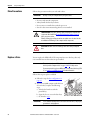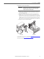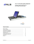
1
User Manual
Non-display Industrial Computers
Catalog Numbers 6177R-MM, 6177R-RM, 6189V-DVIVGA, 6189V-HDDTRAY, 6189V-PCIBARMM, 6189V-PCIBARRM,
6189V-PSU600W, 6189V-RACKSLIDES, 6189V-4GDDR3, 6189V-8GDDR3, 6189V-16GDDR3, 6189V-35HDD500GB, 6189V-35SSD128GB
Important User Information
Read this document and the documents listed in the additional resources section about installation, configuration, and
operation of this equipment before you install, configure, operate, or maintain this product. Users are required to
familiarize themselves with installation and wiring instructions in addition to requirements of all applicable codes, laws,
and standards.
Activities including installation, adjustments, putting into service, use, assembly, disassembly, and maintenance are required
to be carried out by suitably trained personnel in accordance with applicable code of practice.
If this equipment is used in a manner not specified by the manufacturer, the protection provided by the equipment may be
impaired.
In no event will Rockwell Automation, Inc. be responsible or liable for indirect or consequential damages resulting from the
use or application of this equipment.
The examples and diagrams in this manual are included solely for illustrative purposes. Because of the many variables and
requirements associated with any particular installation, Rockwell Automation, Inc. cannot assume responsibility or
liability for actual use based on the examples and diagrams.
No patent liability is assumed by Rockwell Automation, Inc. with respect to use of information, circuits, equipment, or
software described in this manual.
Reproduction of the contents of this manual, in whole or in part, without written permission of Rockwell Automation,
Inc., is prohibited.
Throughout this manual, when necessary, we use notes to make you aware of safety considerations.
WARNING: Identifies information about practices or circumstances that can cause an explosion in a hazardous environment,
which may lead to personal injury or death, property damage, or economic loss.
ATTENTION: Identifies information about practices or circumstances that can lead to personal injury or death, property
damage, or economic loss. Attentions help you identify a hazard, avoid a hazard, and recognize the consequence.
IMPORTANT
Identifies information that is critical for successful application and understanding of the product.
Labels may also be on or inside the equipment to provide specific precautions.
SHOCK HAZARD: Labels may be on or inside the equipment, for example, a drive or motor, to alert people that dangerous
voltage may be present.
BURN HAZARD: Labels may be on or inside the equipment, for example, a drive or motor, to alert people that surfaces may
reach dangerous temperatures.
ARC FLASH HAZARD: Labels may be on or inside the equipment, for example, a motor control center, to alert people to
potential Arc Flash. Arc Flash will cause severe injury or death. Wear proper Personal Protective Equipment (PPE). Follow ALL
Regulatory requirements for safe work practices and for Personal Protective Equipment (PPE).
Allen-Bradley, Rockwell Software, and Rockwell Automation are trademarks of Rockwell Automation, Inc.
Trademarks not belonging to Rockwell Automation are property of their respective companies.
Summary of Changes
This manual contains new and updated information. Changes throughout this
revision are marked by change bars, as shown to the right of this paragraph.
New and Updated
Information
This table contains the changes made to this revision.
Topic
Page
Expanded Abbreviations table
10
Revised and added available operating systems
11
Added Important table
11
Added catalog numbers to table in ‘Computer Options’ section
12
Updated information in ‘Parts List’ section
13
Revised footnote information in ‘Hardware Features’ section
14, 15
Updated CISPR number in ‘Environment and Enclosure Information’ section
20
Added catalog numbers to table in ‘Mounting Hardware’ section
22
Revised information in ‘Functional Ground Screw’ section
29
Changed callout description in Figure 10
42
Revised information in ‘Replace or Add a Memory Module’ section
43
Revised information in ‘Set-up Screen Overview’ section
52
Revised information in both ‘SATA Configuration’ subsections
60, 61
Revised information in ‘Super I/O Configuration’ subsection
65
Consolidated ‘System Temperature History’ subsection into ‘Hardware Monitor’ subsection
67
Revised and added information in ‘Boot’ subsection
70
Revised and added information in ‘Security’ subsection
71
Added information in ‘Diagnostics’ section
73, 74
Added Important tables in ‘AMI Backup’ section
75, 76, 77
Added Important table in ‘AMI Restore’ section
79
Added information in ‘Diagnostics’ section
87
Added Important table in ‘Load the System Defaults’ section
88
Added information in ‘Clear the UEFI’ section
89
Added ‘Dispose of the Computer’ section
90
Added new catalog numbers to Table 5, Hardware and Software Specifications
91
Added new Table 6, Physical Specifications
92
Revised and added information in Table 9, Certifications
94
Rockwell Automation Publication 6177R-UM002D-EN-P - October 2014
3
Summary of Changes
Notes:
4
Rockwell Automation Publication 6177R-UM002D-EN-P - October 2014
Table of Contents
Preface
Preface Objectives. . . . . . . . . . . . . . . . . . . . . . . . . . . . . . . . . . . . . . . . . . . . . . . . . . 9
Purpose of This Manual . . . . . . . . . . . . . . . . . . . . . . . . . . . . . . . . . . . . . . . . . . . . 9
More Resources . . . . . . . . . . . . . . . . . . . . . . . . . . . . . . . . . . . . . . . . . . . . . . . . . . . . 9
Abbreviations. . . . . . . . . . . . . . . . . . . . . . . . . . . . . . . . . . . . . . . . . . . . . . . . . . . . 10
Chapter 1
Features
Chapter Objectives. . . . . . . . . . . . . . . . . . . . . . . . . . . . . . . . . . . . . . . . . . . . . . .
Computer Overview . . . . . . . . . . . . . . . . . . . . . . . . . . . . . . . . . . . . . . . . . . . . .
Operating Systems . . . . . . . . . . . . . . . . . . . . . . . . . . . . . . . . . . . . . . . . . . . . . . .
Computer Options. . . . . . . . . . . . . . . . . . . . . . . . . . . . . . . . . . . . . . . . . . . . . . .
Before You Begin . . . . . . . . . . . . . . . . . . . . . . . . . . . . . . . . . . . . . . . . . . . . . . . .
Parts List . . . . . . . . . . . . . . . . . . . . . . . . . . . . . . . . . . . . . . . . . . . . . . . . . . . . . . . .
Hardware Features . . . . . . . . . . . . . . . . . . . . . . . . . . . . . . . . . . . . . . . . . . . . . . .
750R Computer . . . . . . . . . . . . . . . . . . . . . . . . . . . . . . . . . . . . . . . . . . . . .
1450R Computer . . . . . . . . . . . . . . . . . . . . . . . . . . . . . . . . . . . . . . . . . . . .
Status Indicators . . . . . . . . . . . . . . . . . . . . . . . . . . . . . . . . . . . . . . . . . . . . .
System Boards. . . . . . . . . . . . . . . . . . . . . . . . . . . . . . . . . . . . . . . . . . . . . . . .
11
11
11
12
12
13
13
14
15
16
17
Chapter 2
Installation
Chapter Objectives. . . . . . . . . . . . . . . . . . . . . . . . . . . . . . . . . . . . . . . . . . . . . . .
Installation Precautions. . . . . . . . . . . . . . . . . . . . . . . . . . . . . . . . . . . . . . . . . . .
Environment and Enclosure Information. . . . . . . . . . . . . . . . . . . . . . .
European Union Directive . . . . . . . . . . . . . . . . . . . . . . . . . . . . . . . . . . . .
Installation Guidelines . . . . . . . . . . . . . . . . . . . . . . . . . . . . . . . . . . . . . . . . . . .
Mounting Clearance Requirements. . . . . . . . . . . . . . . . . . . . . . . . . . . . . . . .
Mounting Hardware . . . . . . . . . . . . . . . . . . . . . . . . . . . . . . . . . . . . . . . . . . . . .
Computer Dimensions . . . . . . . . . . . . . . . . . . . . . . . . . . . . . . . . . . . . . . . . . . .
Required Tools . . . . . . . . . . . . . . . . . . . . . . . . . . . . . . . . . . . . . . . . . . . . . . . . . .
Install the Computer . . . . . . . . . . . . . . . . . . . . . . . . . . . . . . . . . . . . . . . . . . . . .
Mount the 750R Computer . . . . . . . . . . . . . . . . . . . . . . . . . . . . . . . . . . .
Mount the 1450R Computer in a Rack Cabinet . . . . . . . . . . . . . . . .
Connect Peripherals. . . . . . . . . . . . . . . . . . . . . . . . . . . . . . . . . . . . . . . . . . . . . .
Internal USB Port . . . . . . . . . . . . . . . . . . . . . . . . . . . . . . . . . . . . . . . . . . . .
Connect Power . . . . . . . . . . . . . . . . . . . . . . . . . . . . . . . . . . . . . . . . . . . . . . . . . .
Functional Ground Screw . . . . . . . . . . . . . . . . . . . . . . . . . . . . . . . . . . . . . . . .
Connect to a Network. . . . . . . . . . . . . . . . . . . . . . . . . . . . . . . . . . . . . . . . . . . .
19
20
20
20
21
22
22
23
23
24
24
26
27
28
29
29
30
Chapter 3
Operation
Chapter Objectives. . . . . . . . . . . . . . . . . . . . . . . . . . . . . . . . . . . . . . . . . . . . . . .
Operating Guidelines. . . . . . . . . . . . . . . . . . . . . . . . . . . . . . . . . . . . . . . . . . . . .
Start the Computer . . . . . . . . . . . . . . . . . . . . . . . . . . . . . . . . . . . . . . . . . . . . . .
Restart the Computer . . . . . . . . . . . . . . . . . . . . . . . . . . . . . . . . . . . . . . . . . . . .
Restart the Computer with the Reset Button . . . . . . . . . . . . . . . . . . .
Shut Down the Computer . . . . . . . . . . . . . . . . . . . . . . . . . . . . . . . . . . . . . . . .
Rockwell Automation Publication 6177R-UM002D-EN-P - October 2014
31
31
32
33
33
34
5
Table of Contents
Chapter 4
Component Replacement
Chapter Objectives . . . . . . . . . . . . . . . . . . . . . . . . . . . . . . . . . . . . . . . . . . . . . . .
Accessories and Replacement Parts. . . . . . . . . . . . . . . . . . . . . . . . . . . . . . . . .
Voltage Precautions . . . . . . . . . . . . . . . . . . . . . . . . . . . . . . . . . . . . . . . . . . . . . .
Electrostatic Discharge Precautions . . . . . . . . . . . . . . . . . . . . . . . . . . . . . . . .
Pre-configuration. . . . . . . . . . . . . . . . . . . . . . . . . . . . . . . . . . . . . . . . . . . . . . . . .
Post-configuration. . . . . . . . . . . . . . . . . . . . . . . . . . . . . . . . . . . . . . . . . . . . . . . .
Required Tools. . . . . . . . . . . . . . . . . . . . . . . . . . . . . . . . . . . . . . . . . . . . . . . . . . .
Remove the Cover. . . . . . . . . . . . . . . . . . . . . . . . . . . . . . . . . . . . . . . . . . . . . . . .
Reinstall the Cover . . . . . . . . . . . . . . . . . . . . . . . . . . . . . . . . . . . . . . . . . . . . . . .
Drive Precautions . . . . . . . . . . . . . . . . . . . . . . . . . . . . . . . . . . . . . . . . . . . . . . . .
Replace a Drive. . . . . . . . . . . . . . . . . . . . . . . . . . . . . . . . . . . . . . . . . . . . . . . . . . .
Replace or Add Memory Modules . . . . . . . . . . . . . . . . . . . . . . . . . . . . . . . . .
Memory Configuration Guidelines. . . . . . . . . . . . . . . . . . . . . . . . . . . . .
Replace or Add a Memory Module . . . . . . . . . . . . . . . . . . . . . . . . . . . . .
Replace the RTC Battery. . . . . . . . . . . . . . . . . . . . . . . . . . . . . . . . . . . . . . . . . .
Replace the Power Supply Unit . . . . . . . . . . . . . . . . . . . . . . . . . . . . . . . . . . . .
35
35
35
36
36
37
37
38
39
40
40
42
43
43
44
46
Chapter 5
UEFI Set-up Utility
6
Chapter Objectives . . . . . . . . . . . . . . . . . . . . . . . . . . . . . . . . . . . . . . . . . . . . . . .
Set-up Utility Overview. . . . . . . . . . . . . . . . . . . . . . . . . . . . . . . . . . . . . . . . . . .
Access the Set-up Utility . . . . . . . . . . . . . . . . . . . . . . . . . . . . . . . . . . . . . . . . . .
Set-up Screen Overview . . . . . . . . . . . . . . . . . . . . . . . . . . . . . . . . . . . . . . . . . . .
Firmware Update. . . . . . . . . . . . . . . . . . . . . . . . . . . . . . . . . . . . . . . . . . . . . . . . .
Firmware Configuration . . . . . . . . . . . . . . . . . . . . . . . . . . . . . . . . . . . . . . . . . .
Common Buttons at the Bottom of Screens. . . . . . . . . . . . . . . . . . . . .
Main . . . . . . . . . . . . . . . . . . . . . . . . . . . . . . . . . . . . . . . . . . . . . . . . . . . . . . . .
Advanced . . . . . . . . . . . . . . . . . . . . . . . . . . . . . . . . . . . . . . . . . . . . . . . . . . . .
Chipset . . . . . . . . . . . . . . . . . . . . . . . . . . . . . . . . . . . . . . . . . . . . . . . . . . . . . .
Boot . . . . . . . . . . . . . . . . . . . . . . . . . . . . . . . . . . . . . . . . . . . . . . . . . . . . . . . . .
Security . . . . . . . . . . . . . . . . . . . . . . . . . . . . . . . . . . . . . . . . . . . . . . . . . . . . . .
Save and Exit . . . . . . . . . . . . . . . . . . . . . . . . . . . . . . . . . . . . . . . . . . . . . . . . .
Diagnostics . . . . . . . . . . . . . . . . . . . . . . . . . . . . . . . . . . . . . . . . . . . . . . . . . . . . . .
AMI Rescue. . . . . . . . . . . . . . . . . . . . . . . . . . . . . . . . . . . . . . . . . . . . . . . . . . . . . .
AMI Backup . . . . . . . . . . . . . . . . . . . . . . . . . . . . . . . . . . . . . . . . . . . . . . . . .
AMI Restore . . . . . . . . . . . . . . . . . . . . . . . . . . . . . . . . . . . . . . . . . . . . . . . . .
Exit . . . . . . . . . . . . . . . . . . . . . . . . . . . . . . . . . . . . . . . . . . . . . . . . . . . . . . . . . . . . .
Rockwell Automation Publication 6177R-UM002D-EN-P - October 2014
51
51
52
52
53
54
54
55
56
69
70
71
72
73
75
76
79
82
Table of Contents
Chapter 6
System Troubleshooting
Chapter Objectives. . . . . . . . . . . . . . . . . . . . . . . . . . . . . . . . . . . . . . . . . . . . . . .
Hardware Monitoring . . . . . . . . . . . . . . . . . . . . . . . . . . . . . . . . . . . . . . . . . . . .
Troubleshooting . . . . . . . . . . . . . . . . . . . . . . . . . . . . . . . . . . . . . . . . . . . . . . . . .
Troubleshooting Checklists. . . . . . . . . . . . . . . . . . . . . . . . . . . . . . . . . . . . . . .
Issues during Startup . . . . . . . . . . . . . . . . . . . . . . . . . . . . . . . . . . . . . . . . .
Issues after Startup . . . . . . . . . . . . . . . . . . . . . . . . . . . . . . . . . . . . . . . . . . .
Issues Running New Software . . . . . . . . . . . . . . . . . . . . . . . . . . . . . . . . .
Issues with the Add-in Card . . . . . . . . . . . . . . . . . . . . . . . . . . . . . . . . . .
Issues with an External Display . . . . . . . . . . . . . . . . . . . . . . . . . . . . . . . .
Diagnostics . . . . . . . . . . . . . . . . . . . . . . . . . . . . . . . . . . . . . . . . . . . . . . . . . . . . . .
Load the System Defaults . . . . . . . . . . . . . . . . . . . . . . . . . . . . . . . . . . . . . . . . .
Clear the UEFI . . . . . . . . . . . . . . . . . . . . . . . . . . . . . . . . . . . . . . . . . . . . . . . . . .
Ship or Transport the Computer . . . . . . . . . . . . . . . . . . . . . . . . . . . . . . . . . .
Dispose of the Computer . . . . . . . . . . . . . . . . . . . . . . . . . . . . . . . . . . . . . . . . .
83
83
84
85
85
85
86
86
86
87
88
89
90
90
Appendix A
Specifications
. . . . . . . . . . . . . . . . . . . . . . . . . . . . . . . . . . . . . . . . . . . . . . . . . . . . . . . . . . . . . . . . . 91
Appendix B
Accessories Installation
Objectives . . . . . . . . . . . . . . . . . . . . . . . . . . . . . . . . . . . . . . . . . . . . . . . . . . . . . . . 95
Pre-installation Checklist . . . . . . . . . . . . . . . . . . . . . . . . . . . . . . . . . . . . . . . . . 95
Install a Second HDD . . . . . . . . . . . . . . . . . . . . . . . . . . . . . . . . . . . . . . . . . . . . 95
Install I/O Card Retention Bracket. . . . . . . . . . . . . . . . . . . . . . . . . . . . . . . . 98
Install an Add-in Card. . . . . . . . . . . . . . . . . . . . . . . . . . . . . . . . . . . . . . . . . . . 100
Install Rack Slides (1450R Computer) . . . . . . . . . . . . . . . . . . . . . . . . . . . . 102
Install More Memory. . . . . . . . . . . . . . . . . . . . . . . . . . . . . . . . . . . . . . . . . . . . 104
Index
. . . . . . . . . . . . . . . . . . . . . . . . . . . . . . . . . . . . . . . . . . . . . . . . . . . . . . . . . . . . . . . . 105
Rockwell Automation Publication 6177R-UM002D-EN-P - October 2014
7
Table of Contents
Notes:
8
Rockwell Automation Publication 6177R-UM002D-EN-P - October 2014
Preface
Preface Objectives
This preface covers the following topics:
• Purpose of This Manual
• More Resources
• Abbreviations
Purpose of This Manual
This manual is a user guide for non-display industrial computers. It provides
procedures to the following:
• Install the computer.
• Make computer connections.
• Operate the computer.
• Troubleshoot the computer.
More Resources
These documents contain more information to related products from Rockwell
Automation.
Resource
Description
Industrial Non-display Computers Product
Information, publication 6177R-PC001
Provides basic product information on the non-display industrial
computers.
Industrial Automation Wiring and
Grounding Guidelines, publication
1770-4.1
Provides general guidelines for installing a Rockwell Automation
industrial system.
You can view or download publications at http://www.rockwellautomation.com/
literature. To order paper copies of technical documentation, contact your local
Allen-Bradley distributor or Rockwell Automation sales representative.
Rockwell Automation Publication 6177R-UM002D-EN-P - October 2014
9
Preface
Abbreviations
10
This publication can use the following abbreviations.
Abbr
Description
Abbr
Description
ACPI
Advanced configuration (and) power
interface
OSK
On-screen keyboard
AHCI
Advanced host controller interface
PCAP
Protective capacitive (touch screen)
AMI
American Megatrends, Inc.
PCB
Printed circuit board
AMT
Active management technology
PCDC
Product Compatibility and Download Center
BIOS
Basic input/output system
PCH
Platform control hub
CF
CompactFlash
PCI
Peripheral component interconnect
CPU
Central processing unit
PCIe
Peripheral component interconnect express
CMOS
Complementary metal oxide semiconductor
PEG
PCI express graphics
COM
Communication (serial port interface)
PELV
Protective extra-low voltage
CRC
Cyclic redundancy check
PERR
PCI parity error
DDR
Double data rate (RAM)
POST
Power on self-test
DIMM
Dual in-line memory module
PSU
Power supply unit
DP
DisplayPort (digital display interface)
PXE
Pre-boot execution environment
DVI
Digital video interface
RAID
Redundant array (of) independent disks
DVMT
Dynamic video memory technology
RAM
Random access memory
ECC
Error correcting code
RIUP
Remove or insert under power
eDP
Embedded DisplayPort
RMS
Root-mean-square
EEA
European Environment Agency
RTC
Real-time clock
EMC
Electromagnetic compatibility
SAS
Serial attached SCSI
EOS
Embedded operating system
SATA
Serial advanced technology attachment
ESD
Electrostatic discharge
SCSI
Small computer system interface
EWF
Enhanced write filter
SELV
Safety extra-low voltage
FAT
File allocation table
SERR
PCI signal error
HDD
Hard disk drive
SPD
Serial presence detect
HORM
Hibernate once, resume many
SSD
Solid-state drive
IDE
Integrated device electronics
TFT
Thin film transistor
IEC
International Engineering Consortium
UEFI
Universal extensible firmware interface
IGD
Intel graphics driver
USB
Universal serial bus
KVM
Keyboard video mouse
UPS
Uninterruptible power source
LAN
Local area network
VBAT
Voltage (battery)
NEMA
National Electrical Manufacturers Association
VDDR
Voltage (DDR RAM)
ODD
Optical disk drive
VGA
Video graphics array
Rockwell Automation Publication 6177R-UM002D-EN-P - October 2014
Chapter
1
Features
Chapter Objectives
This chapter provides information on the following topics:
• Computer Overview
• Operating Systems
• Computer Options
• Before You Begin
• Parts List
• Hardware Features
Computer Overview
Non-display industrial computers run operations from small visual interface and
maintenance applications to large control and information applications.
Combine an industrial display with the 750R (catalog number 6177R-MM) or
1450R (catalog number 6177R-RM) computer to complete your system.
These computers are available with performance, advanced, and server features.
They come standard with a selection of I/O ports for peripheral connections and
expansion slots.
Operating Systems
The following Microsoft-licensed operating systems are available:
• Windows Embedded 8.1 Industry Pro (64-bit)
• Windows 7 Professional, Service Pack 1 (64-bit)
• Windows XP Professional, Service Pack 3
• Windows Server 2012 R2 Standard (64-bit)
• Windows Server 2008 R2 Standard, Service Pack 1(64-bit)
No operating system updates have been applied to the factory image beyond the
service packs.
Computers with HDDs include a recovery partition with the original factory
image. You can use AMI Rescue that is embedded in the BIOS/UEFI set-up
utility to restore the operating system from the recovery partition, and create a
recovery image. See AMI Rescue on page 75 for instructions.
IMPORTANT
Computers with the Windows Embedded 8.1 Industry Pro operating system do
not contain a backup of the factory image in the recovery partition.
Rockwell Automation Publication 6177R-UM002D-EN-P - October 2014
11
Chapter 1
Features
To obtain a copy of a factory system image, contact your local technical support
center or access the Rockwell Automation Product Compatibility and Download
Center (PCDC) at http://www.rockwellautomation.com/support/pcdc.page.
Computer Options
This table summarizes the options that are available for non-display industrial
computers. A comparative summary of features for the computers is in Appendix A,
Specifications on page 91.
Cat. No.
Model
Form Factor
Package
Windows OS
6177R-RMPXP
1450R
4U rack mount
Performance
XP Professional SP3
6177R-RMPW7
7 Professional SP1(1)
6177R-RMPNO
None
6177R-RMRNO
Redundant
6177R-RMAW7
Advanced
7 Professional SP1(1)
Embedded 8.1 Industry Pro(1)
6177R-RMAW8
6177R-RMSS8
Server
Server 2008 R2 Standard SP1(1)
6177R-RMS12
Server 2012 R2 Standard(1)
6177R-RMSNO
None
6177R-MMPXP
750R
Machine mount
Performance
XP Professional SP3
6177R-MMPW7
7 Professional SP1(1)
6177R-MMPNO
None
6177R-MMAW7
Advanced
Embedded 8.1 Industry Pro(1)
6177R-MMAW8
6177R-MMSS8
XP Professional SP3
Server
Server 2008 R2 Standard SP1(1)
6177R-MMS12
Server 2012 R2 Standard(1)
6177R-MMSNO
None
(1) 64-bit operating system.
Before You Begin
Before you unpack the computer, inspect the shipping carton for damage. If
damage is visible, immediately contact the shipper and request assistance.
Otherwise, continue to unpack.
Keep the original packing material in case you must return the computer for
repair or transport it to another location. Use both inner and outer packing
cartons to provide adequate protection for a computer that is returned for service.
12
Rockwell Automation Publication 6177R-UM002D-EN-P - October 2014
Features
Parts List
Chapter 1
The computers ship with the following items.
Item
Description
Hardware
• Power cord for AC power models
• Mounting hardware
– Rack handles for 1450R computers
– Mounting brackets for 750R computers
– Mounting fasteners
– Cable ties for internal USB device
• Keys for door lock for 1450R computers
• Assembly screw bag
• DVI-to-VGA adapter
• CD with CD/DVD creation software(1)
Documents
• Non-display Industrial Computers Product Information, publication 6177R-PC001
• Shipped Compact Discs (CDs) Update Release Note, publication 6000-RN009(1)
• Industrial Computers with the Windows Embedded 8.1 Industry Professional Operating
System Release Note, publication 6000-RN011(2)
• China RoHS hazardous material table insert
• Production test report
(1) Shipped only with computers with the Windows XP Professional operating system.
(2) Shipped only with computers with the Windows Embedded 8.1 Industry Pro operating system.
Hardware Features
The illustrations in this section show the hardware features of each computer:
• Exterior views
– Front panel
– Rear panel
• Status indicators
• System boards
– Motherboard
– Front panel board
– HDD adapter boards
– PCI expansion board
Rockwell Automation Publication 6177R-UM002D-EN-P - October 2014
13
Chapter 1
Features
750R Computer
Figure 1 - Front Panel
Item
1
2
3
8
9
10
4
11
5
12
6
Icon
Component
Item
Icon
Component
1
Power status indicator
7
HDD SATA 1(2)
2
Reset button
8
Disk drive access status
indicator
3
USB 3.0 port
9
System health status indicator
4
ODD access indicator
10
USB 2.0 ports, 2
5
ODD SATA 2
11
ODD eject button
6
HDD SATA 0(1)
12
ODD mechanical eject hole
(1) Computers with Windows Server operating systems ship with two HDDs that are configured for RAID 1 operation. Computers that ship
with two HDDs but no operating system are not configured for RAID 1 operation.
(2) A second HDD is optional for computers with non-server operating systems.
7
Figure 2 - Rear Panel
Item
1
5
11
12
13
14
15
6
7
16
17
4
18
14
Component
Item
Icon
Component
1
PCI expansion slot covers, 4
10
Microphone-in jack
2
Gigabit LAN ports, 2
11
USB 2.0 ports, 4
3
Parallel port
12
eSATAp port
4
Serial COM1 port (RS-232)
13
USB 3.0 port
5
Serial COM2 port (RS-232)
14
DVI-I1 port
6
Power switch
15
DVI-D2 port
7
Functional ground screw
16
PS/2 keyboard port
8
Line-in jack
17
PS/2 mouse port
9
Line-out jack
18
Power input, AC
8
9
10
2
3
Icon
Rockwell Automation Publication 6177R-UM002D-EN-P - October 2014
Features
Chapter 1
1450R Computer
Figure 3 - Front Panel
3
1
2
6
4
5
1
3
2 4
7
11
8
With Door Closed
Item
Icon
9
10
12 13
14
15
With Door Open
Component
Item
Icon
Component
Item
Icon
Component
1
Rack handle
6
Reset button
11
ODD access indicator
2
Power status indicator
7
USB 2.0 ports, 2
12
ODD eject button
3
Disk drive access status indicator
8
Power switch
13
ODD mechanical eject hole
4
System health status indicator
9
USB 3.0 port
14
HDD SATA 0(1)
5
Door lock
10
ODD SATA 2
15
HDD SATA 1(1)(2)
(1) Computers with Windows Server operating systems ship with two HDDs that are configured for RAID 1 operation. Computers that ship with two HDDs but no operating system are not configured for RAID
1 operation.
(2) A second HDD is optional for computers with non-server operating systems.
Figure 4 - Rear Panel
1
3
2
10
Item
Icon
5
4
6
7
8
9
11 12 13 14 15 16
Component
Item
1
PS/2 mouse port
2
Icon
17
Component
Item
7
Gigabit LAN ports, 2
13
USB 3.0 port
Functional ground screw
8
Line-in jack
14
eSATAp port
3
DVI-D2 port
9
Line-out jack
15
USB 2.0 ports, 4
4
Serial COM2 port (RS-232)
10
Power input, AC
16
Microphone-in jack
5
Serial COM1 port (RS-232)
11
PS/2 keyboard port
17
PCI expansion slot covers, 7
6
Parallel port
12
DVI-I1 port
Rockwell Automation Publication 6177R-UM002D-EN-P - October 2014
Icon
Component
15
Chapter 1
Features
Status Indicators
There are three status indicators on the front panel of the 750R and 1450R
computers. These indicators aid in issue diagnosis by providing status
information of different system components.
1
2
3
1450R-Front Panel
750R-Front Panel
Item
1
2
3
16
Icon
Indicator
Status
Description
Power status
Green
The computer is operating.
Flashing orange
The computer is in standby mode.
Off
The computer is off.
Flashing red
HDD or ODD activity.
Off
No HDD or ODD activity.
Red
The computer temperature threshold has been exceeded.
Off
System health is normal.
Disk drive access status
System health status
Rockwell Automation Publication 6177R-UM002D-EN-P - October 2014
Features
Chapter 1
System Boards
The illustrations in this section show the system board layouts for the computers.
The 750R and 1450R computers share system boards except for the PCI
expansion board, which is available only on 1450R computers.
Figure 5 - Motherboard
3
1
36
33
31
4
2
35
34
5
6
7
32
9
8 10
16
30
11
17
12
13
29
27
28
26
25
24
23
22
18
14
19
15
21 20
Item
Component
Item
Component
Item
Component
1
PCI expansion board connector
13
Rear USB 3.0 port
25
Battery socket
2
Clear UEFI (CMOS1) jumper
14
DVI-D2 connector
26
Serial port (COM1)
3
Platform control hub
15
PS/2 keyboard port
27
Internal parallel connector
4
PCI expansion slot
16
Gigabit LAN/2 port
28
Serial port (COM2)
5
PCIe x4 expansion slot
17
Gigabit LAN/1 port
29
Power switch cable connector
6
PCIe x1 expansion slot
18
DVI-I1 connector
30
ATX 24-pin power connector
7
PCIe x16 expansion slot
19
PS/2 mouse port
31
System fan 2 connector
8
Line-in jack
20
+12V 4-pin power connector
32
System fan 1 connector
9
Line-out jack
21
Internal USB 3.0 connector
33
SATA 3.0 cable connector
10
Microphone-in jack
22
LGA1155 processor socket
34
SATA 2.0 cable connector
11
Rear USB 2.0 ports, 4
23
Processor fan connector
35
Internal USB 2.0 connector
12
eSATAp port
24
DDR3 DIMM slots, 4
36
Front panel board cable connector
Rockwell Automation Publication 6177R-UM002D-EN-P - October 2014
17
Chapter 1
Features
Figure 6 - Front Panel Board
6
1
2
3
4
5
Item
Component
Item
Component
1
Reset button
4
System health indicator
2
Power status indicator
5
USB 2.0 ports
3
Disk drive access indicator
6
Front panel board cable connector
Figure 7 - HDD Adapter Boards
Motherboard Interface
1
HDD Tray Interface
2
3
Item
Component
Item
Component
1
SATA cable connectors
3
SATA drive connectors
2
Power connector
Figure 8 - PCI Expansion Board (1450R computers)
1
18
2
3
Item
Component
Item
Component
1
PCI expansion board power connector
3
PCI expansion slots
2
Motherboard connector
Rockwell Automation Publication 6177R-UM002D-EN-P - October 2014
Chapter
2
Installation
Chapter Objectives
This chapter provides information on the following topics:
• Installation Precautions
• Installation Guidelines
• Mounting Clearance Requirements
• Mounting Hardware
• Computer Dimensions
• Required Tools
• Install the Computer
• Connect Peripherals
• Connect Power
• Functional Ground Screw
• Connect to a Network
Review each mounting type and computer dimensions before you install the
computer.
Rockwell Automation Publication 6177R-UM002D-EN-P - October 2014
19
Chapter 2
Installation
Installation Precautions
Read and follow these precautions before you install the computer.
Environment and Enclosure Information
ATTENTION: This equipment is intended for use in a Pollution Degree 2 industrial
environment, in overvoltage Category II applications (as defined in IEC 60664-1),
at altitudes up to 2000 m (6561 ft) without derating.
This equipment is considered Group 1, Class A industrial equipment according to
IEC/CISPR 22. Without appropriate precautions, there can be potential difficulties
with electromagnetic compatibility in other environments due to conducted and
radiated disturbance.
This equipment is supplied as open type equipment. The interior of the enclosure
must be accessible only by the use of a tool. UL Listed equipment need not be
mounted inside another enclosure. Subsequent sections of this publication can
contain extra information about specific enclosure type ratings that are required to
comply with certain product safety certifications.
In addition to this publication, see the following:
• Industrial Automation Wiring and Grounding Guidelines, publication 1770-4.1,
for additional installation requirements
• NEMA 250 and IEC 60529, as applicable, for explanations of the degrees of
protection that are provided by different types of enclosure
European Union Directive
This computer meets the European Union Directive requirements when installed
within the European Union or EEA regions and have the CE mark. A copy of the
declaration of the conformity is available at http://www.rockwellautomation.com/
certification.
ATTENTION: This computer is intended to operate in an industrial or control
room environment, which uses some form of power isolation from the public
low–voltage mains. Some computer configurations cannot comply with the
EN 61000-3-2 Harmonic Emissions standard as specified by the EMC Directive of
the European Union. Obtain permission from the local power authority before
you connect any computer configuration that draws more than 75 W of AC
power directly from the public mains.
To comply with EN 55024, the Ethernet port LAN cable must be only used indoors.
All other I/O cables must be less than 3 m (9.84 ft) and only used indoors.
20
Rockwell Automation Publication 6177R-UM002D-EN-P - October 2014
Installation
Installation Guidelines
Chapter 2
Follow these guidelines to make sure that your computer provides service with
excellent reliability:
• The installation site must have sufficient power.
ATTENTION: To maintain an electrically safe installation, AC powered
computers must be plugged into a grounded outlet.
• In dry environments, static charges can build up easily. A properly
grounded computer helps to reduce static discharges, which can cause
shock and damage electronic components.
• The enclosure must allow sufficient space around air inlets and outlets to
provide the circulation necessary for cooling. See Mounting Clearance
Requirements on page 22 for further information. Never allow air passages
to become obstructed.
• The ambient air temperature must not exceed the maximum operating
temperature that is specified in Table 8 on page 93. Consider a usersupplied fan, heat exchanger, or air conditioner for heat from other devices
in the enclosure.
TIP
Hot air rises. The temperature at the top of the enclosure is often
higher than the temperature in other parts of the enclosure, especially
when air does not circulate.
IMPORTANT
The computer can operate at a range of extremes. However, the life
span of the computer is shortened if you continuously operate it at its
highest rated temperature.
• The humidity of the ambient air must not exceed limits that are specified
in Table 8 on page 93 and must avoid condensation.
• The enclosure or cover must always remain in place during operation. The
cover provides protection against high voltages inside the computer and
inhibits radio-frequency emissions that can interfere with other equipment.
Rockwell Automation Publication 6177R-UM002D-EN-P - October 2014
21
Chapter 2
Installation
Mounting Clearance
Requirements
When selecting an installation site for the computers, allow a minimum of
76 mm (3 in.) clearance at the front and rear of the computer for adequate
ventilation and cable connections.
IMPORTANT
Mounting Hardware
22
Computers generate heat. Therefore, do not operate the computer in an
enclosure with the minimum clearances unless adequate ventilation or other
methods are used to lower the temperature within the enclosure.
Allow enough clearance to install or remove peripheral components, such as
storage drives.
The table lists the hardware that is required for each type of installation.
Description
Cat. No.
Application
Supplied
with
computer?
Mounting
brackets (2)
N/A
Machine or wall
Yes
750R
6177R-MMPXP
6177R-MMPW7
6177R-MMPNO
6177R-MMSS8
6177R-MMS12
6177R-MMAW7
6177R-MMAW8
6177R-MMSNO
1450R
6177R-RMPXP
6177R-RMPW7
6177R-RMPNO
6177R-RMRNO
6177R-RMSS8
6177R-RMS12
6177R-RMAW7
6177R-RMAW8
6177R-RMSNO
Rack handles (2)
N/A
Rack
Yes
Rack slides (2)
6189V-RACKSLIDES
Rack
No
Rockwell Automation Publication 6177R-UM002D-EN-P - October 2014
Applies to
Cat. No.
Installation
Computer Dimensions
Chapter 2
Review computer dimensions to estimate the clearance necessary for computer
installation. Dimensions are given in mm (in.).
Top View
465
(18.3)
Side View
Front View
Front View
360
(14.2)
381 (15)
750R Computers
Required Tools
170
(6.7)
176
(6.9)
1450R Computers
These tools are required for computer installation:
• #2 cross-head screwdriver
• Slot-head screwdriver
• Drill motor and drill bit
• Antistatic wriststrap
Rockwell Automation Publication 6177R-UM002D-EN-P - October 2014
23
Chapter 2
Installation
Install the Computer
The computers support the following mounting options:
• Machine or wall mount (for 750R models)
• Rack mount (for 1450R models)
Mount the 750R Computer
You can mount the 750R computer on any flat surface, such as a shelf inside a
machine or against a wall, by using mounting brackets. Holes are provided on
both sides of the 750R computer for side mounting installation.
TIP
For ease of installation, use two or more people to install the computer.
Follow these steps to mount the 750R computer.
1. Verify that the mounting location provides adequate space for cables and
airflow.
See Mounting Clearance Requirements on page 22 for recommended
allowances.
2. Decide where to locate the mounting brackets (the bottom side for an
upright installation or the side for a wall installation).
3. Attach each mounting bracket to the computer with four screws.
Torque the screws to 1.3 N•m (12.1 lb•in).
Bottom Mounting Brackets
24
Rockwell Automation Publication 6177R-UM002D-EN-P - October 2014
Side Mounting Brackets
Installation
Chapter 2
4. See Figure 9 to decide which mounting holes to use on the bracket.
5. Drill holes in the wall or shelf to accommodate screws sized M6…M8.
Figure 9 - Mounting Hole Locations on 750R Computers
Bottom Mounting Bracket Hole Locations
382.1 (15.04)
240 (9.45)
70.5 (2.78)
60 (2.36)
375
(14.76)
360
(14.17)
210
(8.27)
194
(7.64)
120 (4.73)
Dimensions are in mm (in.).
IMPORTANT: Bottom view is enlarged
for detail and not in scale to front view.
120 (4.73)
120 (4.73)
Mounting Hole Details (all brackets)
A
B
24 (0.95) x 4
Side Mounting Bracket Hole Locations
382.1 (15.04)
70.5 (2.78)
240 (9.45)
185 (7.28)
60 (2.36)
175 (6.89)
401.6
(15.81)
385.6
(15.18)
120 (4.73)
120 (4.73)
120 (4.73)
Callout
Dim, mm (in.) Qty
Description
A
Ø 10 (0.39)
4
Use these mounting holes for the following.
• You are replacing a legacy computer.
• Shock and vibration are not environmental elements.
B
Ø 6.5 (0.25)
8
Use these mounting holes when shock and vibration are environmental
elements.
6. Fasten the computer to the wall or shelf with M6…M8 mounting screws.
Rockwell Automation Publication 6177R-UM002D-EN-P - October 2014
25
Chapter 2
Installation
Mount the 1450R Computer in a Rack Cabinet
You can install the 1450R computer in a rack cabinet that does the following:
• Conforms to EIA standards for equipment with 483 mm (19 in.) wide
panels
• Accommodates the 4U height and depth of the computer
• Provides rear clearance for cables and airflow
A rack cabinet with a depth of 610 mm (24 in.) is sufficient.
IMPORTANT
Rack slides are not supplied with the computer and must be ordered separately.
See Mounting Hardware on page 22 for the catalog number necessary for
ordering.
See Install Rack Slides (1450R Computer) on page 102 if you have purchased
the rack slides.
Support the computer with rack slides or by fastening it to a shelf. The four
flanges of the computer secure the computer horizontally only to the front
mounting rails of the rack cabinet.
TIP
For ease of installation, use two or more people to install the computer.
Follow these steps to mount the 1450R computer.
1. Verify that the mounting location provides adequate space for cables and
airflow.
See Mounting Clearance Requirements on page 22 for recommended
allowances.
2. Attach the supplied rack handles to the computer.
Torque the screws to 1.3 N•m (12.1 lb•in).
3. See Install Rack Slides (1450R Computer) on page 102 on how to install
rack slides to the rack cabinet and the 1450R computer.
26
Rockwell Automation Publication 6177R-UM002D-EN-P - October 2014
Installation
Connect Peripherals
Chapter 2
The following illustration shows the I/O port panel of the computers. Peripheral
components compatible to each port are inside the callout figures.
Figure 10 - 750R and 1450R Computer Peripherals
TIP
• There are three USB ports on the front panel. Use these ports to connect
various USB devices to the computer, such as an external drive.
• You can use a DVI-to-VGA adapter to connect an external VGA display to
the DVI-I1 port of the computer.
Rockwell Automation Publication 6177R-UM002D-EN-P - October 2014
27
Chapter 2
Installation
Internal USB Port
There is an internal USB port for activation dongles or other USB storage
devices. You must first remove the computer cover to access the port.
See Chapter 4 for how to remove and reinstall the computer cover.
Internal USB port secured with factory installed cable tie.
An activation dongle that is connected to internal USB port and secured with the supplied cable ties.
TIP
28
To connect an external device, cut the factory installed cable tie that secures
the internal USB port.
We recommend that you fasten any device that is connected to the internal
USB port with the supplied cable ties.
Rockwell Automation Publication 6177R-UM002D-EN-P - October 2014
Installation
Connect Power
Chapter 2
A grounded, 3-prong IEC60320-C13 power cord provides power to the
computer. The power supply input accepts 100…240V AC and is autoranging.
ATTENTION: When you connect power to the computer for the first time, the
following actions occur:
• The default UEFI setting automatically starts the computer after it is plugged
into a power source.
• You must read and accept an End User Setup procedure for computers with a
Windows operating system (requires an external display).
Do not disconnect power from the system until after the Windows Setup
procedure is completed. If power is disconnected during this procedure, it can
result in a corrupted system image.
Operate the computer in an industrial or control room environment, which uses
some form of power isolation from the public low-voltage mains.
ATTENTION: Supply the computer circuit with its own disconnect. Use an
uninterruptible power source (UPS) to help protect against unexpected power
failure or power surges.
Always shut down the Windows operating system before you disconnect power to
the computer to minimize performance degradation and operating system failures.
Follow these steps to connect the computer to an AC power source.
1. Connect the power cord to the AC power input. See Hardware Features
starting on page 13 for where the power inputs are on each computer
model.
2. Connect the AC power cord to a power source.
SHOCK HAZARD: Connect the AC power cord to a power source with an
earth ground. Failure to follow this warning can result in electrical shock.
3. Apply 100…240V AC power to the computer.
Functional Ground Screw
The pre-installed functional ground screw is not required for safety or regulatory
compliance. If a supplemental ground is desired, use the functional ground screw
on the rear panel of the 750R and 1450R computers. See pages 14 and 15 for
where the functional ground screw is on each computer model.
If you use the functional ground screw, connect the computer to earth ground by
using a 1.5 mm2 (16 AWG) or larger external wire. Use a ground wire with an
insulation color that is approved by the local inspection authority.
Rockwell Automation Publication 6177R-UM002D-EN-P - October 2014
29
Chapter 2
Installation
Connect to a Network
The computers have two 1 GB LAN ports that connect to an Ethernet network
by using CAT5 or CAT5E twisted-pair Ethernet cable with RJ45 connectors. See
Hardware Features starting on page 13 for where the LAN ports are on each
computer model.
IMPORTANT
30
To help prevent performance degradation of Ethernet communication, do not
subject the computer or cables to extreme radiation or conducted
high-frequency noise.
In industrial environments, proper cable routing and power conditioning are
required for Ethernet communication. We recommend that you route all
Ethernet cabling through dedicated metal conduits. For improved performance
reliability, install ferrite bead filters at the cable ends.
Rockwell Automation Publication 6177R-UM002D-EN-P - October 2014
Chapter
3
Operation
Chapter Objectives
This chapter provides information on the following topics:
• Operating Guidelines
• Start the Computer
• Restart the Computer
• Shut Down the Computer
Operating Guidelines
Follow these operating guidelines for your computer:
• If you use an external display, turn on the display first.
SHOCK HAZARD: Do not operate the computer with the covers
removed. An electrical shock hazard exists. All covers are required to
maintain EMI shield.
• Always use the proper power down procedures as required by your
operating system, such as the Shut Down command in the Microsoft
Windows operating system.
• After you shut down the computer, do not apply power again until
shutdown is complete.
For computers with an HDD, the HDD must come to a complete stop,
which can take up to 30 seconds after shutdown is initiated.
Rockwell Automation Publication 6177R-UM002D-EN-P - October 2014
31
Chapter 3
Operation
Start the Computer
Follow these steps to start the computer.
IMPORTANT
The following steps apply to when you must manually start the computer. See
Connect Power on page 29 for when power is applied to the computer for the
first time.
1. Make sure any connected components with separate power supplies (such
as an external display) are turned on first.
2. Make sure all necessary peripheral devices are connected to the corresponding
I/O ports on the computer.
3. If you have a1450R computer and the front
door is locked, complete the following steps:
a. Unlock the front door with the provided
key.
b. Open the door to access the power
switch.
4. Plug the AC power cable into the power
input on the computer and into a power
source or wall outlet.
SHOCK HAZARD: Connect the AC power cord to a power source with an
earth ground. Failure to follow this warning can result in electrical shock.
5. Press the power switch.
See Hardware Features on page 13 for the power switch location.
The computer performs certain actions when it is started or reset. See Restart the
Computer on page 33.
If your computer does not start or you notice other anomalies, refer to the
Troubleshooting on page 84.
32
Rockwell Automation Publication 6177R-UM002D-EN-P - October 2014
Operation
Restart the Computer
Chapter 3
Use any of the following methods to restart your computer:
• From the Start menu, choose Restart.
• Press Ctrl+Alt+Delete on an attached keyboard and click Restart.
• Press the reset button.
During a restart, the computer does the following:
• Clears the RAM.
• Starts the POST.
• Initializes peripheral devices such as drives and printers.
• Loads the operating system.
Use an external display to view the progress of the POST, the initialization of
accessory devices, and the start-up dialogs for the operating system that is installed.
Restart the Computer with the Reset Button
IMPORTANT
Press the reset button only if the system locks up or some other anomaly
occurs.
1. If you have a1450R computer and the front
door is locked, complete the following steps:
a. Unlock the front door with the provided
key.
b. Open the door to access the reset button.
2. Lightly press the tip of a stylus or any other
pointed device to the reset button.
Resetting the 750R Computer
Rockwell Automation Publication 6177R-UM002D-EN-P - October 2014
Resetting the 1450R Computer
33
Chapter 3
Operation
Shut Down the Computer
Use either of the following methods to shut down the computer.
Method
Actions
Windows OS
With an attached mouse, keyboard, and display, do one of the following.
• Press Ctrl+Alt+Delete and click Shut Down.
• From the Start menu, click or choose Shut Down from the pull-down menu.
Power switch
Momentarily press the power switch to shut down the computer. See Hardware
Features on page 13 for the power switch location.
After you shut down the computer, do not apply power again until shutdown is
complete. For computers with an HDD, the HDD must come to a complete
stop, which can take up to 30 seconds after shutdown is initiated.
34
Rockwell Automation Publication 6177R-UM002D-EN-P - October 2014
Chapter
4
Component Replacement
Chapter Objectives
This chapter provides information on the following topics:
• Accessories and Replacement Parts
• Voltage Precautions
• Electrostatic Discharge Precautions
• Pre-configuration
• Post-configuration
• Required Tools
• Remove the Cover
• Reinstall the Cover
• Drive Precautions
• Replace a Drive
• Replace or Add Memory Modules
• Replace the RTC Battery
• Replace the Power Supply Unit
Accessories and Replacement
Parts
You can view a list of accessories and replacement parts at
http://ab.rockwellautomation.com/Computers.
Review the specifications of a new component before you install it to make sure it
is compatible with the computer. Record the model, serial number, and any other
pertinent information of new components for future reference.
IMPORTANT
Voltage Precautions
We recommend that you use only Allen-Bradley approved accessories and
replacement parts.
The computers contain line voltages. Disconnect all power to the computer
before you install or remove components.
SHOCK HAZARD: Disconnect all power to the computer before you remove
components.
Failure to disconnect power can result in severe electrical shock to an individual or
electrostatic discharge (ESD) damage to the computer and components.
Rockwell Automation Publication 6177R-UM002D-EN-P - October 2014
35
Chapter 4
Component Replacement
Electrostatic Discharge
Precautions
ATTENTION: Electrostatic discharge (ESD) can damage static-sensitive devices
or microcircuitry.
• Disconnect all power before you work on the computer as detailed in Voltage
Precautions on page 35.
• Observe proper packaging and grounding techniques to help prevent damage.
Follow these ESD precautions:
• Transport the computer and replacement parts in static-safe containers,
such as conductive tubes, bags, or boxes.
• Keep electrostatic-sensitive parts in their containers until they arrive at the
designated static-free work area.
• Cover the designated work area with approved static-dissipating material:
– Use an antistatic wriststrap that is connected to the work surface.
– Use properly grounded tools and equipment.
• Keep the designated work area free of nonconductive materials, such as
plastic assembly aids and foam packing.
• Avoid contact with pins, leads, or circuitry.
• Always hold components with a printed circuit board (PCB) by its edges
and place it with the assembly side down.
Pre-configuration
IMPORTANT
Before you install hardware or perform maintenance procedures that require
access to internal components, we recommend that you first back up all
computer data to avoid loss.
ATTENTION: Make sure to read and understand all installation and removal
procedures before you configure the computer hardware.
Follow these steps before you remove the cover or you replace a hardware component.
1. Shut down the computer and all peripherals that are connected to it.
2. Disconnect all cables from power outlets to avoid exposure to high energy
levels.
If necessary, label each cable to expedite reassembly.
3. Disconnect telecommunication cables to avoid exposure to a shock hazard
from ring voltages.
36
Rockwell Automation Publication 6177R-UM002D-EN-P - October 2014
Component Replacement
Post-configuration
Chapter 4
Follow these steps after you install or you remove a hardware component.
1. Verify that all components are installed according to instructions.
2. Make sure that no tools or loose parts are left inside the computer.
3. Reinstall any expansion boards, peripherals, chassis cross members, and
system cables that were previously removed.
4. Reinstall the cover according to the instructions on page 39.
5. Reconnect all external cables and power to the computer.
6. Press the power switch to start the computer.
Required Tools
The following tools are required for component replacement:
• #2 cross-head screwdriver
• Antistatic wriststrap
• Side cutters (to cut cable ties, if necessary)
Rockwell Automation Publication 6177R-UM002D-EN-P - October 2014
37
Chapter 4
Component Replacement
Remove the Cover
To install, replace, or upgrade internal computer components, you must first
remove the cover.
Follow these steps to remove the side cover for a 750R computer or the top cover
for a 1450R computer.
1. Follow the steps for Pre-configuration on page 36.
2. Unfasten the cover from the computer chassis:
• 750R computers: Remove the three screws on the rear edge of the side
cover (A).
• 1450R computers: Remove the two screws on the rear edge of the top
cover (A).
3. Slide the cover back about 1.5 cm (0.5 in.) to release the hinge tabs (B).
4. Tilt the cover up slightly to disengage the hinge tabs from their lock slots.
5. Pull the cover away from the chassis (C).
750R Computer
C
B
A
B
C
A
A
B
B
C
C
A
A
1450R Computer
6. After you install, replace, or upgrade internal computer components,
reinstall the cover as detailed in Reinstall the Cover on page 39.
38
Rockwell Automation Publication 6177R-UM002D-EN-P - October 2014
Component Replacement
Reinstall the Cover
Chapter 4
Follow these steps to reinstall the side cover for the 750R computer or the top
cover for the 1450R computer.
1. Verify that the computer is in the upright position.
2. Follow step 1 through step 3 of the Post-configuration on page 37.
3. Position the cover so its hinge tabs align and engage the lock slots on the
chassis (A).
Tilt the cover slightly to make sure that all hinge tabs are engaged and
locked properly.
4. Slide the cover forward to lock the hinge tabs into place (B).
5. Secure the cover to the computer chassis.
• 750R computers: Reinstall the three screws on the rear edge of the side
cover (C).
• 1450R computers: Reinstall the two screws on the rear edge of the top
cover (C).
6. Torque the screws to 0.6 N•m (5.2 lb•in).
750R Computer
B
A
C
B
C
A
C
B
A
B
A
C
1450R Computer
Rockwell Automation Publication 6177R-UM002D-EN-P - October 2014
C
39
Chapter 4
Component Replacement
Drive Precautions
Follow these precautions when you work with a drive.
IMPORTANT
Back up or clone your computer before you replace a drive.
• Do not touch internal components.
• Always handle the drive by its frame.
• Never remove or install a drive with the power on.
• Store the drive in an antistatic bag when it is not installed.
SHOCK HAZARD: Electrostatic discharge (ESD) can damage the computer and
components. Read and follow Electrostatic Discharge Precautions on page 36
before you remove a drive.
Failure to follow proper safety precautions can result in severe electrical shock to
an individual or ESD damage to the computer and its components.
ATTENTION: Mechanical shock can damage a drive. Do not drop or bump the
drive.
Replace a Drive
You can replace the HDD. All 6177R computers have two drive bays, but only
server models have two drives that are pre-installed.
IMPORTANT
This section is to replace an HDD in the first drive bay (SATA 0), which is the top
drive bay in either computer model. See pages 14 and 15 for bay location.
If you want to install or replace an HDD in the second (bottom) drive bay (SATA
1), see Install a Second HDD on page 95 for further information.
Follow these steps to replace an HDD.
1. Follow the steps for Pre-configuration on
page 36.
2. If you have a1450R computer and the front
door is locked, complete the following
steps:
a. Unlock the front door with the
provided key.
b. Open the door to access the drive bays.
c. Go ahead to step 3.
IMPORTANT
40
Use an antistatic wriststrap that is connected to the work surface, and properly
grounded tools and equipment.
Rockwell Automation Publication 6177R-UM002D-EN-P - October 2014
Component Replacement
Chapter 4
3. Remove the HDD assembly from its bay.
a. Loosen the two captive thumbscrews of the HDD assembly (A).
b. Pull the HDD assembly from its bay (B).
750R Computer
1450R Computer
A
A
B
B
A
A
4. Remove the HDD module from its tray.
a. Remove the four mounting screws from the bottom of the tray (C).
b. Detach the tray from the HDD module to be replaced (D).
D
E
Existing
HDD Module
New
HDD Module
Drive Tray
Mounting Screws (4)
C
F
C
C
C
F
F
F
5. Install the new HDD module to the tray.
ATTENTION: Mechanical shock can damage a drive. Do not drop or bump the
drive.
a. Install the new HDD module with the PCB-side down.
b. Fasten the drive tray over the HDD module (E).
c. Secure the drive tray to the module with the four mounting screws (F).
Torque the screws to 0.59 N•m (5.2 lb•in).
Rockwell Automation Publication 6177R-UM002D-EN-P - October 2014
41
Chapter 4
Component Replacement
6. Return the HDD assembly into its bay (G).
7. Tighten the two captive thumbscrews of the drive assembly to secure it to
the computer (H).
750R Computer
1450R Computer
H
H
G
G
H
H
8. Follow the steps for Post-configuration on page 37.
Replace or Add
Memory Modules
The motherboard of the 750R and 1450R computers has four DIMM slots that
support up to 32 GB maximum system memory.
Figure 11 - Memory Module Slots and Module Alignment
Lock Lever
Keyed Surface
of DIMM Slot
4 3 2 1
IMPORTANT
42
When you install memory in pairs, install modules in slots 1 and 3 or slots 2
and 4 for optimal performance.
Rockwell Automation Publication 6177R-UM002D-EN-P - October 2014
Component Replacement
Chapter 4
Memory Configuration Guidelines
Follow these guidelines when you replace or add memory to the computers:
• Use only standard unbuffered memory modules that conform to
non-ECC 240-pin DDR3 SDRAM (PC3-10600) standards.
• Use only DDR3 type memory modules.
• Use only memory modules with gold-plated contacts.
• Always handle a memory module by its edges.
IMPORTANT
We recommend that you use only Allen-Bradley approved memory
modules. See http://ab.rockwellautomation.com/Computers for
qualified replacement parts and accessories.
Replace or Add a Memory Module
Follow these steps to replace or add a memory module.
IMPORTANT
Use an antistatic wriststrap that is connected to the work surface, and properly
grounded tools and equipment.
1. Follow the steps for Pre-configuration on page 36.
2. Remove the computer cover as detailed in Remove the Cover on page 38.
TIP
To install more memory, go ahead to step 5 of this section.
3. Locate the memory module that you want to replace.
See System Boards on page 17 for memory location on the motherboards.
4. Remove the selected memory module.
a. Use your thumbs or two fingers to push open the lock levers, which
release the memory module from its slot for easy removal.
See Figure 11 on page 42.
b. Gently pull out the memory module to remove it from its slot.
c. Place the memory module on a static-dissipating work surface or inside
an antistatic bag.
5. Install the new memory module.
IMPORTANT
When you install memory in pairs, install modules in slots 1 and 3 or
slots 2 and 4 for optimal performance.
a. Hold the memory module by its edges as you remove it from its
antistatic bag.
b. Orient the module so the notch on its bottom edge aligns with the
keyed surface of the DIMM slot.
See Figure 11 on page 42.
TIP
The keyed surface is off center to assist the correct alignment.
c. Press the module fully into the slot to engage the lock levers.
See Figure 11 on page 42.
Rockwell Automation Publication 6177R-UM002D-EN-P - October 2014
43
Chapter 4
Component Replacement
6. Reinstall the computer cover as detailed in Reinstall the Cover on page 39.
7. Follow the steps for Post-configuration on page 37.
Replace the RTC Battery
The computers use nonvolatile memory that
requires an RTC battery to retain system
information when power is disconnected. The
3V, 600 mAh, CR2450 cell lithium battery is
on the motherboard.
The battery must be replaced during the life
of the computer. Battery life depends on the
amount of time the computer is on, or
on-time.
Table 1 - Battery Estimated Life Span
On-time (hrs/wk)
Estimated Battery Life Span (yrs)
0
4
40
5.5
80
7
If the computer does not retain the correct time and date, replace the battery.
ATTENTION: A risk of fire and chemical burn exists if the battery is not handled
properly.
• Do not disassemble, crush, puncture, or short external contacts.
• Do not expose the battery to temperatures higher than the rated temperature
ranges in Table 8 on page 93.
• Do not dispose of a used battery in water or fire.
For safety information on how to handle lithium batteries, see Guidelines for
Handling Lithium Batteries, publication AG-5.4.
Follow these steps to replace the RTC battery.
1. Follow the steps for Pre-configuration on page 36.
2. Remove the computer cover as detailed in Remove the Cover on page 38.
3. For 750R computers, lay the computer on its side (components showing).
44
Rockwell Automation Publication 6177R-UM002D-EN-P - October 2014
Component Replacement
Chapter 4
Remove old battery.
4. If necessary, remove any accessory
boards or cables that prevent access to
Battery Cover
the RTC battery socket.
5. Remove the old battery.
a. Pull the battery cover straight out
of the battery socket.
b. Pull the old battery from its socket.
6. Install the new battery.
a. Insert the new battery with the
positive polarity (+ side) towards
the SO-DIMM memory slots.
Verify that the battery is seated
completely.
TIP
RTC Battery
Socket
Retaining
Latches
Battery Socket
Install new battery.
The socket retaining latches allow only one way for the battery to be
installed.
b. Reinstall the battery cover.
7. Follow the steps for Post-configuration on page 37.
8. During POST, press F2 on an attached keyboard to access the UEFI setup
and reconfigure settings.
See Chapter 5 for more information on UEFI settings.
IMPORTANT
If you replace the battery, then all UEFI settings return to their default
settings. UEFI settings other than default must be reconfigured after
you replace a battery.
This computer contains a sealed lithium battery that could need
replacement during the life of the computer.
At the end of its life, collect the battery that is contained in this computer
separately from any unsorted municipal waste.
Rockwell Automation Publication 6177R-UM002D-EN-P - October 2014
45
Chapter 4
Component Replacement
Replace the Power Supply
Unit
Follow these steps to replace the power supply unit (PSU).
IMPORTANT
Use an antistatic wriststrap that is connected to the work surface, and properly
grounded tools and equipment when you handle internal computer components.
1. Follow the steps for Pre-configuration on page 36.
2. Remove the computer cover as detailed in Remove the Cover on page 38.
3. For 750R computers, lay the computer on its side (components showing).
4. Remove the factory-installed chassis cross member or optional I/O card
retention bracket as detailed in Install I/O Card Retention Bracket on
page 98.
5. Cut the cable ties with side cutters in the following locations.
ATTENTION: The photo shows a 1450R computer, which has six cable
ties to cut. The circle with blue line is the cable tie to the PCI expansion
board, which does not apply to 750R computers.
46
Rockwell Automation Publication 6177R-UM002D-EN-P - October 2014
Component Replacement
Chapter 4
6. For 1450R computers, disconnect the 4-pin power connector from the
PCI expansion board.
7. Disconnect the ATX 24-pin power connector from the motherboard.
Rockwell Automation Publication 6177R-UM002D-EN-P - October 2014
47
Chapter 4
Component Replacement
8. Disconnect the 4-pin power connector from the HDD assembly.
9. Disconnect the 4-pin power connector from the ODD assembly.
48
Rockwell Automation Publication 6177R-UM002D-EN-P - October 2014
Component Replacement
Chapter 4
10. Disconnect the +12V 4-pin power connector from the motherboard.
11. Remove the five screws that secure the PSU to the chassis and chassis
bracket.
Rockwell Automation Publication 6177R-UM002D-EN-P - October 2014
49
Chapter 4
Component Replacement
12. Disconnect the two SATA cables from the HDD assembly.
IMPORTANT
Mark each SATA cable so that you can reconnect them to the correct
port after you install the new PSU.
13. Remove the PSU.
14. Install the new PSU in the reverse order of the removal steps.
a. Step 11: Torque the five screws to 1.4 N•m (12 lb•in) to secure the
new PSU.
b. Step 4: Reinstall the chassis cross member or I/O card retention
bracket as detailed in Install I/O Card Retention Bracket on page 98.
c. Verify that all cables are properly connected before you reinstall the
cover.
d. Remove and replace any cut cable ties.
15. Follow the steps for Post-configuration on page 37.
50
Rockwell Automation Publication 6177R-UM002D-EN-P - October 2014
Chapter
5
UEFI Set-up Utility
Chapter Objectives
This chapter provides information about the set-up utility. It includes an
overview of set-up utility settings that you can change and how to upgrade to a
new universal extensible firmware interface (UEFI). In this chapter, UEFI
replaces Basic Input/Output System (BIOS) to describe the system firmware
except where BIOS is used, such as on a graphical interface.
The chapter covers the following topics:
• Set-up Utility Overview
• Access the Set-up Utility
• Set-up Screen Overview
• Firmware Update
• Firmware Configuration
• Diagnostics
• AMI Rescue
• Exit
Set-up Utility Overview
The set-up utility is a hardware configuration program that is built into the
UEFI. The UEFI is already configured and optimized so there is no need to run
this utility. However, you can run the set-up utility to do the following:
• Change the system configuration.
• Change the UEFI setup when the system detects a configuration error.
• Redefine communication ports to prevent any conflicts.
• Read the current amount of system memory.
• Change the boot drive.
• Set or change the password or make other changes to the security settings.
• Upgrade the system firmware.
• Run the diagnostic utility to determine the cause of system malfunction.
• Restore or back up the operating system.
Rockwell Automation Publication 6177R-UM002D-EN-P - October 2014
51
Chapter 5
UEFI Set-up Utility
Access the Set-up Utility
Follow these steps to access the set-up utility in your computer.
1. Start your computer.
2. During POST, you have two selections to access the set-up utility.
Press
F2
Result
Accesses a graphical interface of set-up environment.
IMPORTANT: Screen shots in this chapter are from the UEFI graphical interface.
DEL (delete)
Set-up Screen Overview
52
Accesses a text mode set-up environment.
The set-up screen is the main screen for the UEFI graphical interface. On the left
are five menu options that are stacked vertically. Each menu button provides
access to information, commands, or configurable options for the following
topics:
• Firmware Update
• Firmware Configuration
• Diagnostics
• AMI Rescue
• Exit
Rockwell Automation Publication 6177R-UM002D-EN-P - October 2014
UEFI Set-up Utility
Firmware Update
Chapter 5
You can update your system firmware from the Firmware Update menu.
Parameter
Description
Browse
Click to navigate to the firmware file saved onto a media.
Firmware file location
Select or type the file name for the firmware file.
Update
Click to initialize the update process.
Exit
Click to exit the set-up utility.
Follow these steps to update the system firmware.
1. Click the Firmware Update menu.
The Firmware Update screen appears.
2. Click Browse to locate the firmware file.
IMPORTANT
The USB mass storage device that contains the firmware file must be
FAT, FAT16, or FAT32 formatted to be recognized.
See http://www.rockwellautomation.com/support/pcdc.page for
revisions and to download firmware files.
3. Click Update.
Rockwell Automation Publication 6177R-UM002D-EN-P - October 2014
53
Chapter 5
UEFI Set-up Utility
Firmware Configuration
You can view and modify the various system parameters from the Firmware
Configuration menu. On the left are six menu options that are stacked vertically.
Menu
Description
Main
Use this menu to view general computer information and for basic system configuration.
Advanced
Use this menu to configure information for the PXE, PCI, ACPI, processor, SATA, USB,
power, video graphics, super I/O, hardware display, and AMT.
Chipset
Use this menu to configure system chipset information.
Boot
Use this menu to configure boot device priority.
Security
Use this menu to set or change user and administrator passwords.
Save and Exit
Allows you to save changes and reset, discard changes and reset, or restore defaults.
Common Buttons at the Bottom of Screens
Most screens have these common buttons.
54
Button
Description
Help
Click for general help on how to use the set-up utility.
Default
Click to load the default values for all set-up options.
Restore
Click to restore all set-up options to previously saved values.
Save
Click to save configuration changes.
Previous (not shown)
Click to navigate to the previous page.
Exit
Click to close the set-up utility.
Rockwell Automation Publication 6177R-UM002D-EN-P - October 2014
UEFI Set-up Utility
Chapter 5
Main
Parameter(1)
Description
BIOS Vendor
BIOS manufacturer
BIOS Version
BIOS version information
Compliancy
Unified Extensible Firmware Interface (UEFI) version information
Build Date and Time
Date and time BIOS was created.
Total Memory
Total system memory and memory type (in parentheses)
System Date
Set the system date.
Format: Weekday MM:DD:YYYY (Weekday Month:Day:Year)
System Time
Set the system time.
Format: HH:MM:SS (Hour:Minute:Second)
Runtime Hours
Records the total hours of computer runtime.
Manufacturer
System manufacturer
Catalog Number
Allen-Bradley catalog number with series letter
WIN Number
Warranty information number
Version-SYS
System revision, manufacture date
Version-Board
System board version information
Serial Number
Unique system serial number
(1) See page 54 for an explanation of common buttons near the bottom of screen.
Rockwell Automation Publication 6177R-UM002D-EN-P - October 2014
55
Chapter 5
UEFI Set-up Utility
Advanced
Legacy OpROM Support
Parameter(1)
Description
Enable PXE Boot
Enables or disables boot option for legacy network devices.
Options: Enabled or Disabled (default)
(1) See page 54 for an explanation of common buttons near the bottom of screen.
56
Rockwell Automation Publication 6177R-UM002D-EN-P - October 2014
UEFI Set-up Utility
Chapter 5
PCI Subsystem Settings
Parameter(1)
Description
PCI Bus Driver Version
Displays the PCI bus driver version information.
PERR# Generation
Enables or disables PCI Device to Generate PERR#.
Options: Enabled or Disabled (default)
SERR# Generation
Enables or disables PCI Device to Generate SERR#.
Options: Enabled or Disabled (default)
(1) See page 54 for an explanation of common buttons near the bottom of screen.
Rockwell Automation Publication 6177R-UM002D-EN-P - October 2014
57
Chapter 5
UEFI Set-up Utility
ACPI Settings
Parameter(1)
Description
ACPI Sleep State
Select the highest ACPI sleep state the system enters when the SUSPEND button is
pressed.
Options: Suspend Disabled, S1 (CPU Stop Clock), or S3 (Suspend to RAM [default])
(1) See page 54 for an explanation of common buttons near the bottom of screen.
58
Rockwell Automation Publication 6177R-UM002D-EN-P - October 2014
UEFI Set-up Utility
Chapter 5
CPU Configuration
Parameter(1)
Description
CPU Configuration
Displays processor type and maximum speed.
Processor Cores
Displays processor core count.
CPU Speed
Displays maximum speed of the processor.
64-bit
Displays 64-bit support status.
Hyper-threading(2)
Enables or disables the hyper-threading technology.
Options: Enabled (default) or Disabled
Intel Virtualization Technology
(VT-x)
When enabled, a Virtual Memory Manager (VMM) can use the additional hardware
capabilities from Vanderpool Technology.
Options: Enabled or Disabled (default)
Intel Virtualization Technology
for Directed I/O (VT-d)(3)
Enables or disables VT-d.
Options: Enabled or Disabled (default)
(1) See page 54 for an explanation of common buttons near the bottom of screen.
(2) Supported on systems with i3-2120 processors.
(3) Supported on systems with i5-2400 processors.
Rockwell Automation Publication 6177R-UM002D-EN-P - October 2014
59
Chapter 5
UEFI Set-up Utility
SATA Configuration (for computers with Windows 8.1, 7, or XP operating systems)
Parameter(1)
Description
SATA Mode
Select an operation mode for the onboard SATA controller.
Options: Disabled, IDE Mode, AHCI Mode (default), or RAID Mode(2)
SATA Port (0, 1, 2, 4)
Indicates the SATA HDD connected to the SATA connector.
Hot Plug
Enables or disables hot plug support for the SATA port.
Options: Enabled (default) or Disabled
IMPORTANT: Make sure all writes to HDD are complete before your remove the
HDD from the system to avoid risk of data corruption.
External SATA Port
Enables or disables eSATA port.
Options: Enabled (default) or Disabled
(1) See page 54 for an explanation of common buttons near the bottom of screen.
(2) Applies only to computers that ship with Windows Server operating systems. For computers that ship with two HDDs but no
operating system, the HDDs are in AHCI mode instead of RAID and each drive acts independently.
60
Rockwell Automation Publication 6177R-UM002D-EN-P - October 2014
UEFI Set-up Utility
Chapter 5
SATA Configuration (for computers with Windows Server operating systems)
Parameter(1)
Description
SATA Mode
Select an operation mode for the onboard SATA controller.
Options: Disabled, IDE Mode, AHCI Mode, or RAID Mode (default)(2)
SATA Port (0, 1, 2, 4)
Indicates that the SATA HDD is connected to the SATA connector.
Hot Plug
Enables or disables hot plug support for the SATA port.
Options: Enabled (default) or Disabled
External SATA Port
Enables or disables eSATA port.
Options: Enabled (default) or Disabled
(1) See page 54 for an explanation of common buttons near the bottom of screen.
(2) Applies only to computers that ship with Windows Server operating systems. For computers that ship with two HDDs but no
operating system, the HDDs are in AHCI mode instead of RAID and each drive acts independently.
Rockwell Automation Publication 6177R-UM002D-EN-P - October 2014
61
Chapter 5
UEFI Set-up Utility
USB Configuration
Parameter(1)
Description
Front USB 2.0 Ports
Enables or disables the front USB 2.0 ports.
Options: Enabled (default) or Disabled
USB 3.0 Controller
Enables or disables the USB 3.0 controller.
Options: Enabled (default) or Disabled
(1) See page 54 for an explanation of common buttons near the bottom of screen.
62
Rockwell Automation Publication 6177R-UM002D-EN-P - October 2014
UEFI Set-up Utility
Chapter 5
Power Configuration
Parameter(1)
Description
Restore AC Power Loss
Specify what state to go to when power is reconnected after a power failure
(G3 state).
Options: Power off, Power on (default), Last State
(1) See page 54 for an explanation of common buttons near the bottom of screen.
Rockwell Automation Publication 6177R-UM002D-EN-P - October 2014
63
Chapter 5
UEFI Set-up Utility
Intel Integrated Graphics
Parameter(1)
Description
DVMT Memory
Select a video memory size that can be allocated as graphics memory in the DVMT
mode.
Options: 128 MB, 256 MB (default), Maximum
(1) See page 54 for an explanation of common buttons near the bottom of screen.
64
Rockwell Automation Publication 6177R-UM002D-EN-P - October 2014
UEFI Set-up Utility
Chapter 5
Super I/O Configuration
Parameter(1)
Description
Super I/O Chip
Displays the Super I/O chipset information.
Serial Port 1 Configuration
Select to set parameters for serial port 1.
Serial Port 2 Configuration
Select to set parameters for serial port 2.
Parallel Port Configuration
Select to set parameters for the parallel port.
(1) See page 54 for an explanation of common buttons near the bottom of screen.
Rockwell Automation Publication 6177R-UM002D-EN-P - October 2014
65
Chapter 5
UEFI Set-up Utility
Table 2 - Serial Port 1 Configuration
Parameter
Description
Serial Port 1
Enables or disables the serial (COM1) port.
Options: Enabled (default) or Disabled
Device Settings
Displays the Base I/O address and IRQ setting of serial port 1.
Change Settings
Select an optimal setting for the super I/O device.
Options: Auto (default), I/O=3F8h; IRQ=4, I/O=2F8h; IRQ=4, I/O=3E8h; IRQ=4,
I/O=2E8h; IRQ=4
Table 3 - Serial Port 2 Configuration
Parameter
Description
Serial Port 2
Enables or disables the serial (COM2) port.
Options: Enabled (default) or Disabled
Device Settings
Displays the Base I/O address and IRQ setting of serial port 2.
Change Settings
Select an optimal setting for the super I/O device.
Options: Auto (default), I/O=2F8h; IRQ=3, I/O=3F8h; IRQ=3, I/O=3E8h; IRQ=3,
I/O=2E8h; IRQ=3
Table 4 - Parallel Port Configuration
66
Parameter
Description
Parallel Port
Enable or disables the parallel (LPT/LPTE) port.
Options: Enabled (default) or Disabled
Device Settings
Displays the Base I/O address and IRQ setting of the parallel port.
Change Settings
Select an optimal setting for the super I/O device.
Options: Auto (default), I/O=378h; IRQ=5, I/O=278h; IRQ=5, I/O=3BCh; IRQ=5
Device Mode
Select a printer mode.
Options: Standard Parallel Port Mode (default), EPP Mode, ECP Mode, EPP Mode,
and ECP Mode
Rockwell Automation Publication 6177R-UM002D-EN-P - October 2014
UEFI Set-up Utility
Chapter 5
Hardware Monitor
Parameter(1)
Description
Hardware Monitor
System temperature
PCH temperature
CPU temperature
SYS Fan1 Speed
SYS Fan2 Speed(2)
Vcore
VDDR3
+12V
+5V
+3.3V
+1.05Vtt
VBAT
Displays the current readings for temperatures (°C), fan speeds, and core voltages
of various hardware components.
All values are read-only.
System Temperature History
Sensor 1 Max
Sensor 1 Min
Sensor 2 Max
Sensor 2 Min
Sensor 3 Max
Sensor 3 Min
Displays the minimum and maximum temperatures (°C) for applicable sensors
over a 24-hour time period (time stamp is 24-hour clock).
• Sensor 1 is near the front intake fan.
• Sensor 2 is near the CPU.
• Sensor 3 is near the PCH.
All values are read-only.
(1) See page 54 for an explanation of common buttons near the bottom of screen.
(2) Applies only to rack-mounted computers.
Rockwell Automation Publication 6177R-UM002D-EN-P - October 2014
67
Chapter 5
UEFI Set-up Utility
AMT Configuration
Parameter(1)
Description
Intel Management Engine
Version
Displays the Intel Management Engine version.
Execute MEBx
Enables the Management Engine BIOS Extension (MEBx), which is accessed by
pressing Ctrl+P at POST. This function is used to configure AMT.
Options: Enabled or Disabled (default)
Unconfigure AMT/ME
Lets you unconfigure any provisioned management settings for AMT/ME.
Options: Enabled or Disabled (default)
IMPORTANT: ‘Unconfigure AMT/ME’ appears only when ‘Execute MEBx’ is
enabled.
(1) See page 54 for an explanation of common buttons near the bottom of screen.
68
Rockwell Automation Publication 6177R-UM002D-EN-P - October 2014
UEFI Set-up Utility
Chapter 5
Chipset
Parameter(1)
Description
Initiate Graphic Adapter
Select which graphics controller to use as the primary boot device.
Options: PCI/PEG, PEG/IGD (default), PEG/PCI
LAN/1
Enables or disables onboard LAN/1 controller.
Options: Enabled (default) or Disabled
LAN/2
Enables or disables onboard LAN/2 controller.
Options: Enabled (default) or Disabled
Azalia HD Audio
Enables or disables Azalia HD audio.
Options: Enabled (default) or Disabled
(1) See page 54 for an explanation of common buttons near the bottom of screen.
Rockwell Automation Publication 6177R-UM002D-EN-P - October 2014
69
Chapter 5
UEFI Set-up Utility
Boot
Parameter(1)
Description
Bootup NumLock State
Enables or disables the Num Lock key on boot.
Option: On (default), Off
Quiet Boot
Enables or disables Quiet Boot option.
Option: Enabled or Disabled (default)
IMPORTANT: When enabled, this option hides the POST screen messages at
computer startup.
Boot Priority List
Change the boot order. By default, these devices are the boot priority:
1. USB key
2. CD-ROM
3. HDD
4. PXE
5. UEFI Shell
6. PCI/PCIe RAID/SCSI/SAS card
Follow instructions in the dialog box to change the boot order, and to enable or
disable options.
USB Boot Priorities(2)
Change the USB boot order through a dialog box.
Follow instructions to change the boot order, and to enable or disable options.
CD-DVD ROM Boot Priorities(3)
Change the CD-DVD ROM boot order through a dialog box.
Follow instructions to change the boot order, and to enable or disable options.
Hard-Drive Boot Priorities
Change the hard drive boot order through a dialog box.
Follow instructions to change the boot order, and to enable or disable options.
(1) See page 54 for an explanation of common buttons near the bottom of screen.
(2) This data field is visible only when a USB device is connected to the computer during startup.
(3) This data field is visible only on computers with CD-DVD ROM devices.
70
Rockwell Automation Publication 6177R-UM002D-EN-P - October 2014
UEFI Set-up Utility
Chapter 5
Security
Parameter(1)
Description
Administrator Password
Sets the administrator password. Use this password to reduce access risk from
unauthorized or malicious sources.
IMPORTANT: If you forget the administrator password, there are two ways to reset it:
• Remove and replace the battery; see Replace the RTC Battery on page 44 for
more information.
• Clear the UEF; see Clear the UEFI on page 89 for more information.
User Password
Sets the user password. Use this password to reduce access risk from unauthorized
or malicious sources.
IMPORTANT: If you forget the user password, there are two ways to reset it:
• Remove and replace the battery; see Replace the RTC Battery on page 44 for
more information.
• Clear the UEF; see Clear the UEFI on page 89 for more information.
(1) See page 54 for an explanation of common buttons near the bottom of screen.
Rockwell Automation Publication 6177R-UM002D-EN-P - October 2014
71
Chapter 5
UEFI Set-up Utility
Save and Exit
Parameter(1)
Description
Save Changes and Reset
Saves changes that are made and closes the set-up utility.
Discard Changes and Reset
Discards changes that are made and closes the set-up utility.
Restore Defaults
Loads the optimal defaults in the set-up menu.
(1) See page 54 for an explanation of common buttons near the bottom of screen.
72
Rockwell Automation Publication 6177R-UM002D-EN-P - October 2014
UEFI Set-up Utility
Diagnostics
Chapter 5
The Diagnostics menu lets you run the diagnostics utility to determine the cause of
the system malfunction by testing computer components, such as the processor,
memory, HDD, ODD, video, and other hardware.
Select a menu option by pressing the up ↑ or down ↓ arrow keys and pressing
Enter when a menu is highlighted. Press the left ← or right → arrow keys to
toggle between the six Diagnostics menu selections.
Rockwell Automation Publication 6177R-UM002D-EN-P - October 2014
73
Chapter 5
UEFI Set-up Utility
The following table lists the shortcut options in the Diagnostics menu.
74
Button
Description
Esc
Stops a test in progress or exits Diagnostics from any of the six menu options.
Enter
Runs the highlighted test or option.
F1
Displays the Help screens.
F2
Edits batch parameters.
F3
Loads batch parameters.
F4
Saves batch parameters.
F5
Selects or deselects the current test.
F6
Selects or deselects all tests in menu.
F7
Selects or deselects all tests.
F8
Selects or deselects all quick tests.
F9
Displays a list of the Diagnostic function keys.
F10
Runs the selected tests.
Rockwell Automation Publication 6177R-UM002D-EN-P - October 2014
UEFI Set-up Utility
AMI Rescue
Chapter 5
The AMI Rescue menu lets you back up the system image on your computer and
restore that image.
IMPORTANT
The following instructions are for the built-in backup and restore utility, AMI
Rescue. You can also use third party utility or software to create an image
backup and restore.
System images are also available from the Rockwell Automation Product
Compatibility and Download Center:
http://www.rockwellautomation.com/support/pcdc.page.
The AMI Backup function does the following:
• Overwrites any data that is stored in a hidden partition.
• Saves any data as a new image file stored in a hidden partition.
• Saves any data on a mass storage device.
The AMI Restore function overwrites any data on the primary operating system
partition on the HDD.
Parameter
Description
AMI Backup
Click to take you through the steps to back up the desired data.
AMI Restore
Click to take you through the steps to restore the desired data.
Select Volume
Select the volume where to export the backed-up data. Or, select the volume from
which the backed-up data is imported.
Next
Click to go ahead to the next step.
Exit (F4)
Click to close AMI Rescue. Or, press F4 to close AMI Rescue.
Rockwell Automation Publication 6177R-UM002D-EN-P - October 2014
75
Chapter 5
UEFI Set-up Utility
AMI Backup
Follow these steps to back up the system image.
1. Click the AMI Rescue menu to access the AMI Rescue screen.
2. Click AMI Backup.
3. Select the appropriate volume from the list.
‘Recovery’ is the volume name where the default backup of factory images
is stored.
IMPORTANT
Computers with the Windows Embedded 8.1 Industry Pro operating
system do not contain a factory image backup in the Recovery partition.
IMPORTANT
Any USB mass storage drive or eSATA hard disk drive must be formatted
as FAT32, have a drive label other than ‘Recovery,’ and be non-blank.
4. Click Next.
5. Enter a name for the back-up volume.
76
Rockwell Automation Publication 6177R-UM002D-EN-P - October 2014
UEFI Set-up Utility
Chapter 5
A default back-up name is provided.
6. Click Advanced.
7. Select which disk partition you want.
TIP
IMPORTANT
All checkboxes must be selected for a complete backup of the drive.
A recovery (25000 MB) partition is visible on computers with the
Windows Embedded 8.1 Industry Pro operating system.
Do not select this partition for backup.
8. Click OK.
Rockwell Automation Publication 6177R-UM002D-EN-P - October 2014
77
Chapter 5
UEFI Set-up Utility
9. Click Backup to start the back-up process.
78
Rockwell Automation Publication 6177R-UM002D-EN-P - October 2014
UEFI Set-up Utility
Chapter 5
AMI Restore
Perform the following steps to restore your computer from a system image backup.
IMPORTANT
When you restore from a back-up image, all data on the target drive is
replaced. Verify that all data is backed up before you proceed with the
following steps.
1. Click the AMI Rescue menu to access the AMI Restore screen.
2. Click AMI Restore.
3. Select the appropriate volume from the list.
‘Recovery’ is the volume name where the default backup of factory images
is stored.
IMPORTANT
Computers with the Windows Embedded 8.1 Industry Pro operating
system do not contain a factory image backup in the Recovery partition.
IMPORTANT
Any USB mass storage drive or eSATA hard disk drive must be formatted
as FAT32, have a drive label other than ‘Recovery,’ and be non-blank.
4. Click Next.
Rockwell Automation Publication 6177R-UM002D-EN-P - October 2014
79
Chapter 5
UEFI Set-up Utility
5. Select the volume label from which you want to restore.
Default OS image backups begin with an eight character prefix such as
‘NNGR80XF’.
6. Click Advanced.
7. Select to which disk partition you want to restore.
TIP
All checkboxes must be selected for a complete restore of factory OS
images.
8. Click OK.
9. Click Restore to start the restoration process.
80
Rockwell Automation Publication 6177R-UM002D-EN-P - October 2014
UEFI Set-up Utility
Chapter 5
10. An alert window appears (‘Target partitions will be overwritten.
Continue?’). Click Yes.
11. A second alert window appears (‘Do you want to keep the current
partition table?’). Click No.
Rockwell Automation Publication 6177R-UM002D-EN-P - October 2014
81
Chapter 5
UEFI Set-up Utility
12. A third alert window appears (‘The current partition table will be restored
to previous state. Continue?’). Click Yes.
13. The restoration process starts.
Exit
82
The Exit menu closes the set-up utility.
Rockwell Automation Publication 6177R-UM002D-EN-P - October 2014
Chapter
6
System Troubleshooting
Chapter Objectives
This chapter provides information on the following topics:
• Hardware Monitoring
• Troubleshooting
• Troubleshooting Checklists
• Diagnostics
• Load the System Defaults
• Clear the UEFI
• Ship or Transport the Computer
Hardware Monitoring
The built-in hardware monitor of the computer tracks the operating threshold
levels of the voltage and temperature sensors.
Follow these steps to determine whether an operating threshold has been reached.
1. Shut down the computer by using the appropriate method for the installed
operating system.
See Shut Down the Computer on page 34 for more information.
2. Apply power to the computer.
3. During POST, press F2 to access the UEFI set-up utility.
4. Click Firmware Configuration on the Main Menu screen.
5. Click Advanced on the Firmware Configuration main screen.
Rockwell Automation Publication 6177R-UM002D-EN-P - October 2014
83
Chapter 6
System Troubleshooting
6. Click Hardware Monitor on the Advanced screen.
See Hardware Monitor on page 67 for what information is shown.
Use this menu to determine if there is an issue with internal voltages or
component temperatures.
Troubleshooting
Follow these steps to identify and isolate an issue with computer operation.
1. Shut down the computer by using the appropriate method for the installed
operating system.
See Shut Down the Computer on page 34 for more information.
2. Disconnect power to the computer.
3. Disconnect all peripheral devices from the computer.
4. If a keyboard and mouse is used, verify that they are properly connected.
5. If an external display is used, verify that it is properly connected.
6. Connect power to the computer. During POST, one of three events occurs:
• The start-up process is completed.
• A nonfatal error occurs and the related error message is displayed.
• A fatal error occurs and the start-up process terminates.
If
Then
The computer starts
Disconnect all peripheral devices and reconnect them one
at a time until the issue occurs.
The issue is with a specific software or driver
Reinstall the software or driver.
The issue is not related specifically to software,
a driver, or a peripheral device
See the troubleshooting checklists.
TIP
84
Some computers emit beeps. These audible alerts only signal that an
error is detected. The beeps can apply to nonfatal and fatal errors.
Rockwell Automation Publication 6177R-UM002D-EN-P - October 2014
System Troubleshooting
Troubleshooting Checklists
Chapter 6
To manage common issues, use these checklists to test and verify components. If
an issue occurs, refer to these checklists before you call technical support.
Issues during Startup
Are all connections secure?
Are the device drivers installed?
Are the jumpers on any add-in boards correctly positioned?
If the computer starts from a drive:
– Is the drive formatted and set up in the UEFI?
– Are the data and power cables for the drive properly connected? Verify
that the computer can start from an external bootable device.
– Is the drive tray secure? Verify that any captive thumbscrews are not
loose or missing.
• Are memory modules properly installed? You can reinstall them to be sure
of a good connection.
• Is the UEFI properly configured? To restore the default UEFI settings, see
Load the System Defaults on page 88.
•
•
•
•
Issues after Startup
• If an issue is intermittent, you can have a loose connection. Verify that the
following items are secure or properly installed:
– All connections to the computer
– Any add-in cards
– Any captive thumbscrews for the drive assembly
– The memory modules
• Does your computer have a virus? Run an anti-virus software.
• Is the UEFI properly configured? To restore the default UEFI settings, see
Load the System Defaults on page 88.
• If there is a flickering display or a locked computer, restart the computer as
specified in Restart the Computer on page 33. Although the computers
have a regulated and protected power supply, a transient voltage in the
power line or peripheral cable can cause errors.
• Is the data cable to the drive properly connected? Verify that the computer
can start from an external bootable device.
• Is the computer overheating? See the system health status indicator on the
front panel of the computer. The light indicates that the temperature
threshold has been exceeded.
If the system health status indicator remains lit, verify the following:
– Any fan (if available) is working.
– Any fan filter (if available) is clean.
– Any cooling method (such as heat sink and vents) is not blocked.
– There is proper clearance as detailed in Mounting Clearance
Requirements on page 22.
– The air temperature is within the operating range that is specified in
Table 8 on page 93.
Rockwell Automation Publication 6177R-UM002D-EN-P - October 2014
85
Chapter 6
System Troubleshooting
Issues Running New Software
• Does the software have a hardware requirement that is not present?
• Is the software an authorized copy? Some software does not work without
proper activation.
• Did you install the software correctly? Reinstall the software.
• Did you follow the instructions that were provided with the software?
Review any instructions that are provided by the software vendor.
Issues with the Add-in Card
• Is the card installed and configured correctly? Verify the jumper and other
configuration settings.
• Are the card cables properly connected?
• Is the add-in card recognized in Device Manager?
• A card issue that is not listed here? See troubleshooting information
supplied by the add-in card manufacturer.
Issues with an External Display
• Are the display contrast and brightness controls properly adjusted? See the
operating system for video driver set-up functions.
• Verify that the selected character color is not the same as the background
color.
• Is the display compatible with the selected video mode?
• Is the video cable properly connected?
• Is the video driver properly installed?
• Restart the computer with the external display connected and turned on.
• Is display function erratic? Connect the display to another computer to
verify that it functions properly.
86
Rockwell Automation Publication 6177R-UM002D-EN-P - October 2014
System Troubleshooting
Diagnostics
Chapter 6
If you completed the troubleshooting steps and issues remain, use the Diagnostics
menu in the UEFI set-up utility to isolate the issue. Diagnostics tests computer
components to determine the cause of a malfunction.
IMPORTANT
An external keyboard and monitor must be connected to the computer to
perform these steps.
Press F2 during POST or press F10 at any time to access the UEFI set-up utility:
• F2 during POST accesses the main menu of the UEFI set-up utility.
Select Diagnostics on the main menu.
• F10 directly accesses the Diagnostics menu of the UEFI set-up utility.
See Diagnostics on page 73 for more information.
Follow these steps to save diagnostic reports.
1. From the Options menu, select Generate Report and press Enter.
2. Select Report destination and press Enter.
3. Select File and press Enter.
4. Select the device path to generate the log report and press Enter.
If you must generate the report in the current file system, press Enter.
Otherwise, select Continue and press Enter.
5. Enter log file details (file name and heading) for the report.
The default file name is AMIDiag.LOG.
6. Set the report parameters, such as log errors, log test activities, log test start
time, log test end time, log errors only, log errors only with time, Append
to old log file, Log device info on fail, Log device info on abort.
7. To exit the submenu, select Continue and press Enter.
You do not need to disconnect or move your computer to perform an initial
diagnosis. The selected test affects the process, which can take as little as 5
minutes or as long as 8 hours. After Diagnostics has run, you can generate a
report for analysis by a technical support representative, which expedites any
necessary repair process.
Rockwell Automation Publication 6177R-UM002D-EN-P - October 2014
87
Chapter 6
System Troubleshooting
Load the System Defaults
If the computer fails after you change the set-up menus, load the system default
settings to correct the error. These default settings have been selected to optimize
computer performance.
Follow these steps to load the system defaults.
IMPORTANT
An external keyboard and mouse must be connected to the computer to
perform these steps.
1. Restart the computer as specified in Restart the Computer on page 33.
2. During POST, press F2 on an attached keyboard to access the UEFI set-up
utility.
3. Click Firmware Configuration on the set-up screen.
4. Click Default (A) on the Main screen.
5. Click Save (B) to save your changes.
6. Click Exit (C) to close the UEFI set-up utility.
A
88
Rockwell Automation Publication 6177R-UM002D-EN-P - October 2014
B
C
System Troubleshooting
Clear the UEFI
Chapter 6
You must clear the system configuration values that are stored in the UEFI if the
following conditions are present:
• The system configuration has been corrupted
• An incorrect setting has caused error messages to be unreadable
• You cannot access the UEFI set-up utility to load the system defaults
Follow these steps to clear the UEFI.
1. Back up all system data and then shut down the computer.
2. Follow the steps for Pre-configuration on page 36.
3. Remove the cover as detailed in Remove the Cover on page 38.
IMPORTANT
Use an antistatic wriststrap that is connected to a grounded surface.
4. Locate the Clear UEFI (CMOS1) jumper
on the motherboard.
Jumper
Block
See Figure 5 on page 17 for its location.
5. Remove the jumper block from its default
position (over pins 1 and 2).
6. Place the jumper block over pins 2 and 3
for 10 seconds.
7. Return the jumper block to its default
position.
IMPORTANT
Pins
Default
Position
1 2 3
Clear UEFI
Position
The jumper block must be returned to its default position over pins 1
and 2. The computer does not start if you leave the jumper block over
pins 2 and 3.
8. Reinstall the cover as detailed in Reinstall the Cover on page 39.
9. Follow the steps for Post-configuration on page 37.
IMPORTANT
When you clear the UEFI, all UEFI settings return to their defaults. Settings
other than default must be reconfigured after the UEFI is cleared.
10. During POST, press F2 on an attached keyboard to access the UEFI set-up
utility and reconfigure settings.
Rockwell Automation Publication 6177R-UM002D-EN-P - October 2014
89
Chapter 6
System Troubleshooting
Ship or Transport the
Computer
If you must ship the computer via common carrier or otherwise transport it to
another location for service or any other reason, then you must first uninstall the
computer and place it in its original packing material.
ATTENTION: Do not ship or transport the computer when it is installed in a
machine, panel, or rack. To avoid damage to the computer, you must uninstall the
computer and place it in its original packing material before you ship it. Rockwell
Automation is not responsible for any damage to a computer that is shipped or
transported while installed in a machine, panel, or rack.
Dispose of the Computer
At the end of its life, collect the computer separately from any unsorted municipal
waste.
You cannot dispose of computer equipment like other waste material. Most
computers and monitors contain heavy metals that can contaminate the earth.
Therefore, check with local health and sanitation agencies for ways to dispose of
computer equipment.
When a storage drive is part of what you plan to dispose, then permanently erase
any data on it or destroy the drive before it is disposed.
90
Rockwell Automation Publication 6177R-UM002D-EN-P - October 2014
Appendix
A
Specifications
The following tables contain specifications for 750R and 1450R non-display
computers. For more specifications, go to
http://ab.rockwellautomation.com/Computers.
Table 5 - Hardware and Software Specifications
750R (Cat. No. 6177R-MM)
Specifications Attribute
PXP
Hardware
Display
Requires external display
Processor
Intel Core i3-2120
(3.3 GHz, 2C)
Intel Core i5-2400 (3.1 GHz, 4C)
Intel Core i3-2120 (3.3 GHz,
2C)
Intel Core i5-2400 (3.1 GHz, 4C)
Hyperthreading
Yes
No
Yes
No
Turboboost
No
Yes (3.4 GHz max)
No
Yes (3.4 GHz max)
PCH
Intel Q67 Express
Remote
management
Intel AMT 7.0
(without KVM)
Intel AMT 7.0 (with KVM)
Intel AMT 7.0 (without KVM)
Intel AMT 7.0 (with KVM)
Graphics controller
Intel HD2000
Video resolution
(max)
1920 x 1200
Ethernet LAN
PW7
PNO
AW7 AW8
SS8
1450R (Cat. No. 6177R-RM)
S12
SNO
PXP
PW7
PNO
RNO
AW7 AW8
SS8
S12
SNO
10/100/1000 Mbps, 2 ports; Intel 82579LM (LAN/1) and Intel 82574L (LAN/2)
Thermal solution
· 1 chassis fan
· 1 heatsink fan
· 2 chassis fans
· 1 heatsink fan
Expansion slots
·
·
·
·
·
·
·
·
1 PCI
1 PCI-express x16(1)
1 PCI-express x4
1 PCI-express x1
4 PCI
1 PCI-express x16(1)
1 PCI-express x4
1 PCI-express x1
System memory
Supplied
4 GB (2 x 2 GB)
8 GB (2 x 4 GB)
Maximum
32
GB
Memory type
DDR3-1333, PC3-10600, non-ECC
Memory slots
4
4 GB (2 x 2 GB)
8 GB (2 x 4 GB)
Hard disk drive (HDD)
Quantity
1
Size (min/each)
500 GB, 3.5 in.
Interface
SATA
Optical disc drive
(ODD)
2
1
2
1
2
Slim DVD-RW
(1) 150 W max with included 6/8 pin PCIe power connector.
Rockwell Automation Publication 6177R-UM002D-EN-P - October 2014
91
Appendix A
Specifications
Table 5 - Hardware and Software Specifications (continued)
750R (Cat. No. 6177R-MM)
Specifications
Hardware
(continued)
Attribute
PXP
I/O ports
•
•
•
•
•
•
•
•
•
•
•
RAID 1 enabled
PNO
AW7 AW8
SS8
S12
SNO
PXP
PW7
PNO
RNO
AW7 AW8
SS8
Yes
No
Yes
Yes
RAID capabilities
RAID 0 or RAID 1
Audio controller
Azalia HD Audio
Audio codec
Realtek ALC269
Audio jacks
• 1 line-in
• 1 line-out
• 1 mic-in
Operating system
See page 11
BIOS/UEFI vendor
AMI (compliance with UEFI 2.1)
No
(1) With second HDD installed and RAID array configured.
(2) DVI-I port can be converted to VGA with supplied adapter.
Table 6 - Physical Specifications
92
S12
SNO
2 front USB 2.0, 1 internal USB 2.0
1 front USB 3.0
4 rear USB 2.0
1 rear USB 3.0
2 serial (RS-232)
2 Ethernet (each at 10/100/1000 Mbps)
1 parallel
1 eSATAp (5V, 500 mA)
2 DVI (1 DVI-I, 1 DVI-D)(2)
1 PS/2 keyboard
1 PS/2 mouse
No
(1)
Software
PW7
1450R (Cat. No. 6177R-RM)
Attribute
750R (Cat. No. 6177R-MM), 1450R (Cat. No. 6177R-RM)
Dimensions (HxWxD), approx
750R
1450R
360 x 170 x 381 mm (14.17 x 6.69 x 15.01 in.)
176 x 431 x 465 mm (6.93 x 16.97 x 18.31 in.)
Weight, approx
750R
1450R
13.8 kg (30.36 lb)
14.0 kg (30.80 lb)
Mounting option
750R
1450R
Machine mount
4U rack mount
Rockwell Automation Publication 6177R-UM002D-EN-P - October 2014
No
Specifications
Appendix A
Table 7 - Power Specifications
Attribute
750R (Cat. No. 6177R-MM), 1450R (Cat. No. 6177R-RM)
Input voltage, AC
100…240V, autoranging
Line frequency, AC
50/60 Hz
Power consumption, AC
100…240V; 10…5 A 50/60 Hz
Power management
Compliance with ACPI
Power supply
600 W, 80 PLUS Bronze efficiency
Table 8 - Environmental Specifications
Attribute
750R (Cat. No. 6177R-MM), 1450R (Cat. No. 6177R-RM)
Temperature, operating
0…50 °C (32…113 °F)
Temperature, nonoperating
-20…60 °C (-4…140 °F)
Relative humidity
10…90% noncondensing
Shock, operating
15 g (1/2 sine, 11 ms)
Shock, nonoperating
30 g (1/2 sine, 11 ms)
Acoustic noise, idle
750R
1450R
44.3 dB at 50 cm
46.6 dB at 50 cm
Acoustic noise, max
750R
1450R
63.4 dB at 50 cm
64.4 dB at 50 cm
Vibration, operating
0.006 in p-p, 10…57 Hz, 1.0 g peak, 57…640 Hz
Vibration, nonoperating
0.012 in p-p, 10…57 Hz, 2.0 g peak, 57…640 Hz
Rockwell Automation Publication 6177R-UM002D-EN-P - October 2014
93
Appendix A
Specifications
Table 9 - Certifications
Attribute (1)
750R (Cat. No. 6177R-MM), 1450R (Cat. No. 6177R-RM)
cULus
UL/c-UL Listed per UL 60950-1 and CSA C22.2 60950-1 second edition
CE
EMC 2004/108/EEC
• Immunity standards: EN55024, EN61000-3-2, EN61000-3-3
• Emission standards: EN55022 Class A
EN 60950-1
Low voltage directive: LVD 2006/95/EC
FCC
Class A emissions
RCM
Emission standards: AS/NZS CISPR 22 Class A
Korea
Korean Registration of Broadcasting and Communications Equipment, in compliance with
Article 58-2 of Radio Waves Act, Clause 3
Emissions standards: Class A
이 기기는 업무용 (A 급 ) 전자파적합기기로서 판매자 또는 사용자는 이 점을 주의
하시기 바라며 , 가정 외의 지역에서 사용하는 것을 목적으로 합니다 .
RoHS
European RoHS 2011/65/EU
China RoHS:
Turkey RoHS (EEE Yönetmeliğine Uygundur. In Conformity with the EEE Regulation)
(1) See http://www.rockwellautomation/certification for declarations of conformity, certificates, and other certification details.
94
Rockwell Automation Publication 6177R-UM002D-EN-P - October 2014
Appendix
B
Accessories Installation
Objectives
This appendix provides information on how to install accessories available for
this computer.
This appendix covers the following topics:
• Pre-installation Checklist
• Install a Second HDD
• Install I/O Card Retention Bracket
• Install an Add-in Card
• Install Rack Slides (1450R Computer)
• Install More Memory
You can view a current list of accessories at this Rockwell Automation website at
http://ab.rockwellautomation.com/Computers.
ATTENTION: To avoid voiding your computer warranty, we recommend that
you use only Allen-Bradley approved accessories.
Pre-installation Checklist
Review the following information before you install any accessories:
• Voltage Precautions on page 35
• Electrostatic Discharge Precautions on page 36
Install a Second HDD
You can install another HDD in the secondary bay (SATA 1). All 6177R
computers have two HDD bays but only server models have two HDDs that are
pre-installed.
Follow these steps to install a second HDD.
1. Follow the steps for Pre-configuration on page 36.
2. 1450R computers: perform step 2 on page 40 before proceeding to
step 3.
TIP
Use an antistatic wriststrap that is connected to the work surface, and
properly grounded tools and equipment.
Rockwell Automation Publication 6177R-UM002D-EN-P - October 2014
95
Appendix B
Accessories Installation
3. Remove the HDD assembly from the secondary bay.
a. Loosen the two captive thumbscrews of the HDD assembly (A).
b. Pull out the HDD assembly from its bay (B).
750R Computer
1450R Computer
A
A
B
B
A
A
4. Remove the weight from the drive tray.
a. Remove the four mounting screws from the bottom of the weight (C).
b. Detach the tray from the weight (D).
E
D
HDD Module
Weight
HDD Tray
Mounting Screws (4)
C
96
F
C
C
C
Rockwell Automation Publication 6177R-UM002D-EN-P - October 2014
F
F
F
Accessories Installation
Appendix B
5. Install the new HDD module to the tray.
ATTENTION: Mechanical shock can damage an HDD module. Do not
drop or bump the HDD module.
a. Install the new HDD module with the PCB-side down.
b. Fasten the tray over the HDD module (E).
c. Secure the tray to the HDD module with the four mounting screws (F).
Torque the screws to 0.59 N•m (5.2 lb•in).
6. Return the HDD assembly into its bay (G).
7. Tighten the two captive thumbscrews of the HDD assembly to secure it to
the computer (H).
750R Computer
1450R Computer
H
H
G
G
H
H
8. Follow the steps for Post-configuration on page 37.
Rockwell Automation Publication 6177R-UM002D-EN-P - October 2014
97
Appendix B
Accessories Installation
Install I/O Card Retention
Bracket
All 750R and 1450R computers have a factory-installed chassis cross member. An
I/O card retention bracket (catalog number 6189V-PCIBARMM for 750R
computers and catalog number 6189V-PCIBARRM for 1450R computers)
provides extra support to seat I/O cards in applications where shock and
vibration are issues.
Follow these steps to install the I/O card retention bracket.
1. Follow the steps for Pre-configuration on page 36.
2. Remove the computer cover as detailed in Remove the Cover on page 38.
3. Remove the factory-installed chassis cross member.
a. 750R computers: Remove the two screws that secure the chassis cross
member (A).
1450R computers: Remove the four screws that secure the chassis cross
member (A).
Save all screws to install the I/O card retention bracket.
b. 750R computers: Slide the chassis cross member to the right to release
the seating slots (B).
c. Detach the cross member from the chassis (C).
A
A
C
A
C
B
A
750R Computer
98
Rockwell Automation Publication 6177R-UM002D-EN-P - October 2014
1450R Computer
Accessories Installation
Appendix B
4. Install the I/O card retention bracket.
Verify that each sleeve of the I/O card retention bracket is properly
aligned with its add-in card before you perform step 4a for 750R
computers and step 4c for 1450R computers.
IMPORTANT
a. 750R computers: Slide the I/O card retention bracket to the left to
secure the seating slots (D).
b. Align the I/O card retention bracket with the mounting holes (E).
c. 750R computers: Secure the I/O card retention bracket to the chassis
with the two screws from the factory-installed chassis cross member (F).
1450R computers: Secure the I/O card retention bracket to the chassis
with the four screws from the factory-installed chassis cross member (F).
d. Torque the screws to 0.6 N•m (5.2 lb•in).
F
F
E
F
E
D
F
750R Computer
1450R Computer
5. Reinstall the computer cover as detailed in Reinstall the Cover on page 39.
6. Follow the steps for Post-configuration on page 37.
Rockwell Automation Publication 6177R-UM002D-EN-P - October 2014
99
Appendix B
Accessories Installation
Install an Add-in Card
The motherboard of the 750R and 1450R computers has four PCI slots that
support installation of half-length PCI add-in cards.
• One PCI slot
• Three PCI-express (PCIe) slots
Besides these four PCI slots, the 1450R computer has a slot expansion board that
provides another three PCI slots.
PCI expansion board slots of
the 1450R computer.
Motherboard PCI expansion slots
for 750R and 1450R computers.
ATTENTION: Add-in cards are sensitive to ESD; handle with care.
• Hold cards only by the edges.
• Do not touch the card connectors, components, or circuits.
• After you remove an add-in card, place it on a flat, static-free surface, with the
component side up.
• Do not slide the card over any surface.
IMPORTANT
Use an antistatic wriststrap that is connected to the work surface, and properly
grounded tools and equipment.
Follow these steps to install an add-in card.
1. Follow the steps for Pre-configuration on page 36.
2. Remove the cover as detailed in Remove the Cover on page 38.
3. Remove the chassis cross member or I/O card retention bracket as detailed
in Install I/O Card Retention Bracket on page 98.
4. Locate an empty PCI slot.
100
Rockwell Automation Publication 6177R-UM002D-EN-P - October 2014
Accessories Installation
Appendix B
5. Remove the screw that secures the slot cover of the selected PCI slot (A).
6. Pull out the slot cover (B) and store it.
IMPORTANT
Do not discard the slot cover. If the add-in card is removed in the
future, the slot cover must be reinstalled to maintain proper cooling.
7. Remove the add-in card from its protective packaging.
8. Slide the add-in card into the selected PCI slot (C).
Press to verify that it is firmly seated.
9. Secure the add-in card bracket to the chassis with its screw (D).
B
A
B
A
C
D
C
D
Install an add-in card on the 750R computer.
Install an add-in card on the 1450R computer.
10. Connect any necessary cables to the card.
11. Reinstall the chassis cross member or I/O card retention bracket as
detailed in Install I/O Card Retention Bracket on page 98.
IMPORTANT
The chassis cross member or I/O card retention bracket must be
installed for vibration and shock purposes.
12. See any installation instructions that came with the add-in card to verify
that all installation steps are followed.
13. Follow the steps for Post-configuration on page 37.
Rockwell Automation Publication 6177R-UM002D-EN-P - October 2014
101
Appendix B
Accessories Installation
Install Rack Slides
(1450R Computer)
You can install the 1450R computer in a rack cabinet. The computer must be
supported by rack slides or fastened to a shelf.
Follow these steps to install the rack slides and mount the 1450R computer in a
rack cabinet.
1. Remove the inner rails from each rack slides.
a. Extend the inner rail from the rack slide until the rail-release latch clicks
(A).
b. Depress the inner rail-release latch and slide the inner rail out (B).
B
A
2. Attach each rack slide to the computer by using five screws in the holes
marked ‘2.’
Torque the screws to 1.3 N•m (12.1 lb•in).
3. Attach the left and right mounting rails at the desired U position in the
rack cabinet by using four screws (C), two adapter plates (D), and four
nuts (E) for each mounting rail (F).
4. Extend the middle sliding piece of each mounting rail forward until you
hear an audible click (G).
102
Rockwell Automation Publication 6177R-UM002D-EN-P - October 2014
Accessories Installation
Appendix B
5. Align the rack slides to the corresponding slides inside the cabinet, and
insert the rack slides attached to the server into the mounting rails (H).
For ease of installation, make sure two or more people help to install
the computer.
TIP
6. Depress the locking latch and push the computer completely into the rack
until you hear a click sound (G).
See step 1 on page 102 for further information.
7. Secure the computer to the front of the rack cabinet by using four screws
(H).
Torque the screws to 1.3 N•m (12.1 lb•in).
F
D
F
C
D
E
C
E
G
H
I
J
8. Align the rack slides to each slide inside the cabinet, and insert the rack
slides attached to the server into the mounting rails (H).
9. Depress the locking latch and push the computer completely into the rack
until you hear a click sound (I).
See step 3 on page 102 for further information.
Rockwell Automation Publication 6177R-UM002D-EN-P - October 2014
103
Appendix B
Accessories Installation
10. Secure the computer to the front of the rack cabinet by using four screws ( J).
Torque the screws to 1.3 N•m (12.1 lb•in).
11. Follow the steps for Post-configuration on page 37.
Install More Memory
The motherboard of the 750R and 1450R computers has four DIMM slots that
support up to 32 GB maximum system memory.
See Replace or Add Memory Modules on page 42 for further information on
installing more memory.
104
Rockwell Automation Publication 6177R-UM002D-EN-P - October 2014
Index
Numerics
1450R
product dimensions 23
rack mounting 26, 102
rear panel 15
750R
front panel 14
machine mounting 24
product dimensions 23
rear panel 14
A
accessories 35
add-in cards
install 100
troubleshoot 86
audio jacks 27
B
BIOS Setup utility 51
access 52
Setup screen 52
C
CMOS clear 89
configuration tools
installation 23
D
diagnostic utility
usage 73
DIMM slots
install memory 43, 46
location 42
disk drive access indicator 14, 15
F
features
hardware 13
system boards 17
technical specifications 91
Firmware Configuration
Advanced 56
Boot 70
Chipset 69
Main 55
Save & Exit 72
Security 71
front panel
750R 14
front panel board 18
functional ground screw lug
usage 29
H
hard disk drive
precautions 40
removal 40
replace 40, 95
specifications 91
hardware diagnostics 83
hardware features
1450R exterior 15
750R exterior 14
status indicators 16
system boards 17
hardware monitor 83
HDD board 18
hold-down bar
reinstall 101
remove 98
I
installation
environment and enclosure notice 20
functional ground connection 29
guidelines 21
machine mounting 24
mounting hardware 22
network connection 30
power connection 29
product dimensions 23
rack mounting 26, 102
required tools 23
M
machine mounting 24
memory
install 42
installation guidelines 43
motherboard 17
mounting hardware 22
N
network connection
Ethernet LAN 91
LAN cable reminder 20
specification 30
Rockwell Automation Publication 6177R-UM002D-EN-P - October 2014
105
Index
O
operating
guidelines 31
optical disc drive
specifications 91
P
parts list 13
PCI expansion board 18
PCI slots
intall add-in cards 98, 100
peripheral connections
I/O ports
1450R 15
750R 14
illustration 27
POST, see Power On Self Test
power connection
notices 29
specification 29
power management 93
Power On Self Test
product options 12
R
rack mounting 26, 102
RAID operation 14, 15
rear panel
1450R 15
750R 14
replace components
add-in cards 100
memory module 42
post-configuration procedure 37
pre-configuration procedure 36
remove side cover 38
RTC battery 44
replacement parts 35, 95
RTC battery
disposal reminders 44
estimated life span 44
location 44
replace 44
106
S
Setup menu 52
AMI Rescue 75
Diagnostics 73
Exit 82
Firmware Configuration 54
Firmware Update 53
shut down procedure 34
side cover
reinstall 39
remove 38
system
defaults 88
start 32
system boards
front panel board 18
HDD board 18
motherboard 17
PCI expansion board 18
T
thermal solution 91
troubleshooting
add-in card installation 86
after boot-up 85
clearing CMOS 89
diagnostic utility 87
display 86
during boot-up 85
hardware monitor 83
load system defaults 88
procedure 52, 84
U
unpacking reminders 12
Rockwell Automation Publication 6177R-UM002D-EN-P - October 2014
Rockwell Automation Support
Rockwell Automation provides technical information on the Web to assist you in using its products.
At http://www.rockwellautomation.com/support you can find technical and application notes, sample code, and links to
software service packs. You can also visit our Support Center at https://rockwellautomation.custhelp.com/ for software
updates, support chats and forums, technical information, FAQs, and to sign up for product notification updates.
In addition, we offer multiple support programs for installation, configuration, and troubleshooting. For more
information, contact your local distributor or Rockwell Automation representative, or visit
http://www.rockwellautomation.com/services/online-phone.
Installation Assistance
If you experience a problem within the first 24 hours of installation, review the information that is contained in this
manual. You can contact Customer Support for initial help in getting your product up and running.
United States or Canada
1.440.646.3434
Outside United States or Canada
Use the Worldwide Locator at http://www.rockwellautomation.com/rockwellautomation/support/overview.page, or contact your local
Rockwell Automation representative.
New Product Satisfaction Return
Rockwell Automation tests all of its products to help ensure that they are fully operational when shipped from the
manufacturing facility. However, if your product is not functioning and needs to be returned, follow these procedures.
United States
Contact your distributor. You must provide a Customer Support case number (call the phone number above to obtain one) to your
distributor to complete the return process.
Outside United States
Please contact your local Rockwell Automation representative for the return procedure.
Documentation Feedback
Your comments will help us serve your documentation needs better. If you have any suggestions on how to improve this
document, complete this form, publication RA-DU002, available at http://www.rockwellautomation.com/literature/.
Rockwell Automation maintains current product environmental information on its website at
http://www.rockwellautomation.com/rockwellautomation/about-us/sustainability-ethics/product-environmental-compliance.page.
Rockwell Otomasyon Ticaret A.Ş., Kar Plaza İş Merkezi E Blok Kat:6 34752 İçerenköy, İstanbul, Tel: +90 (216) 5698400
Publication 6177R-UM002D-EN-P - October 2014
Supersedes Publication 6177R-UM002C-EN-P - February 2014
PN-XXXXXX-XX
Copyright © 2014 Rockwell Automation, Inc. All rights reserved. Printed in the U.S.A.