1
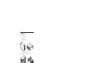
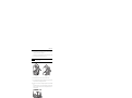
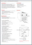
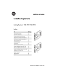
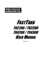
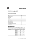
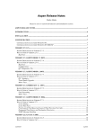
Installation Instructions
RAID System
Catalog Number 6189V-RAIDSATA
Topic
Page
Install the RAID Card
4
Apply the RAID Identification Label
6
Remove the HDD Tray
7
Install the PCI Card Driver
8
Install the RAID Application
10
Reconfigure the SATA Cables
12
Verify RAID Card BIOS Version
14
Verify Proper SATA Cable Connections
14
Install a New Hard Disk Drive
17
Configure the RAID BIOS
18
Configure the System BIOS
22
Validate RAID Installation
24
HDD Indicator
26
Hard Disk Drive Failure
26
Hot Swapping
26
Additional Resources
27
About This Publication
This publication describes how to install, configure, and validate the Redundant Array of
Independent Drives (RAID) system on your 6177R VersaView Light Industrial Computer.
The procedures in this document show how to set up a RAID system using the existing hard
disk drive (HDD) and a new HDD. With the RAID system, your disk drives will operate as
one data storage unit providing a redundant drive system. By storing the same data on two
hard drives, either hard drive can fail without data loss or system downtime. If one drive fails,
it can be replaced without interrupting normal operation.
Publication 6177R-IN005B-EN-P - November 2009
2
RAID System
Important User Information
Solid state equipment has operational characteristics differing from those of electromechanical equipment.
Safety Guidelines for the Application, Installation and Maintenance of Solid State Controls (publication
SGI-1.1 available from your local Rockwell Automation sales office or online at
http://literature.rockwellautomation.com) describes some important differences between solid state
equipment and hard-wired electromechanical devices. Because of this difference, and also because of the
wide variety of uses for solid state equipment, all persons responsible for applying this equipment must
satisfy themselves that each intended application of this equipment is acceptable.
In no event will Rockwell Automation, Inc. be responsible or liable for indirect or consequential damages
resulting from the use or application of this equipment.
The examples and diagrams in this manual are included solely for illustrative purposes. Because of the many
variables and requirements associated with any particular installation, Rockwell Automation, Inc. cannot
assume responsibility or liability for actual use based on the examples and diagrams.
No patent liability is assumed by Rockwell Automation, Inc. with respect to use of information, circuits,
equipment, or software described in this manual.
Reproduction of the contents of this manual, in whole or in part, without written permission of Rockwell
Automation, Inc., is prohibited.
Throughout this manual, when necessary, we use notes to make you aware of safety considerations.
WARNING
IMPORTANT
ATTENTION
Identifies information about practices or circumstances that can cause an explosion in
a hazardous environment, which may lead to personal injury or death, property
damage, or economic loss.
Identifies information that is critical for successful application and understanding of
the product.
Identifies information about practices or circumstances that can lead to personal injury
or death, property damage, or economic loss. Attentions help you to identify a hazard,
avoid a hazard, and recognize the consequences.
SHOCK HAZARD
Labels may be on or inside the equipment, for example, a drive or motor, to alert
people that dangerous voltage may be present.
BURN HAZARD
Labels may be on or inside the equipment, for example, a drive or motor, to alert
people that surfaces may reach dangerous temperatures.
Publication 6177R-IN005B-EN-P - November 2009
RAID System
3
Electrostatic Discharge (ESD) Precautions
ATTENTION
Electrostatic discharge (ESD) can damage static-sensitive devices or
microcircuitry. Observe proper packaging and grounding techniques to prevent
damage. Follow the precautions listed below.
• Transport the computer and replacement parts in static-safe containers such as
conductive tubes, bags, or boxes.
• Keep electrostatic-sensitive parts in their containers until they arrive at static-free
stations.
• Cover workstations with approved static-dissipating material. Use a wrist strap
connected to the work surface and properly grounded (earthed) tools and equipment.
• Keep work area free of nonconductive materials, such as ordinary plastic assembly
aids and foam packing.
• Avoid touching pins, leads, or circuitry.
• Always handle the hard disk drive by its metal frame and do not touch its internal
components.
• Always hold components with a printed circuit board (PCB) by its edges and lay it
with the assembly-side down.
Back Up the Hard Drive
IMPORTANT
It is important that you back up all program data on your hard drive as a
precautionary measure before following the procedures in these instructions.
Parts List
These items are shipped with the RAID system.
•
•
•
•
•
•
RAID controller, PROMISE TX2300
RAID drive identification label
Antistatic wrist strap
Cable tie
White, VersaView Accessories CD
Installation instructions
Publication 6177R-IN005B-EN-P - November 2009
4
RAID System
Install the RAID Card
Follow these steps to install the RAID card in your computer.
1. Shut down the operating system.
2. Disconnect the power cord from the computer.
3. Put on your antistatic wrist band.
4. Remove the chassis cover.
a. Remove screws that secure the cover.
b. Slide cover back and pull panel away from chassis.
XX
.X XX
XX
XX.XXXXX.XX
.X X
750R Computer
1450R Computer
5. Remove the hold-down bar to access the PCI slots.
a. Remove the screws that secure the hold-down bar.
b. Detach the hold-down bar from the chassis.
c. Remove the screw securing the slot cover opposite the selected PCI slot.
d. Pull out the slot cover.
750R Computer
Publication 6177R-IN005B-EN-P - November 2009
1450R Computer
RAID System
5
6. Insert the RAID card into the selected PCI slot applying uniform pressure along the
entire top edge of the card until it is fully seated.
When the card is correctly installed in the PCI slot, the connector pins are not visible.
7. Secure the add-in card bracket to the chassis with its screw.
IMPORTANT
Take precautions to prevent screws or other debris from entering the fan area
of the power supply.
750R Computer
1450R Computer
8. Reattach the hold-down bar to the chassis, then secure it with the screws.
9. Adjust the hold-down clamp by loosening the center screw, adjusting the height of the
clamp to the RAID card, and tightening the center screw.
10. Remove the security screw on the 750R computer that prevents removal of the HDD
bays.
Later procedures require you to remove the unused HDD tray and install a new hard
disk drive. You will not be able to do this on the 750R computer unless the security
screw is removed first.
750R Computer Only
Publication 6177R-IN005B-EN-P - November 2009
6
RAID System
Do not reconfigure the Serial ATA (SATA) cables at this time. You will
do this in a later procedure.
IMPORTANT
11. Reinstall the chassis cover.
XX.XXXXX.XX
XX
.X XX
XX
.X X
750R Computer
1450R Computer
Apply the RAID Identification Label
Apply the supplied RAID identification label next to the hard drives on your computer. The
RAID label will help you to identify a drive if a failure occurs.
Before affixing the label, make sure that the number 2 is next to the top drive and number 1 is
next to the bottom drive.
1450R Computer
RAID
DEVICE
2
1
RAID Label
750R Computer
RAID
DEVICE
2
RAID
DEVICE
2
1
1
Publication 6177R-IN005B-EN-P - November 2009
RAID System
7
Remove the HDD Tray
This procedure has you remove the unused HDD tray from the top HDD bay.
Before starting the procedure, do the following.
• Verify that the HDD security screw is removed from the 750R computer. This screw
prevents removal of the hard disk drive.
• Unlock the front door (if necessary) on the 1450R computer and open to access the
HDD bays.
Follow these steps to remove the unused HDD tray from the top HDD bay.
1. Remove the HDD tray from the top HDD bay, the bay for RAID Device 2.
RAID Device 2
RAID Device 1
2. Verify that your existing hard disk drive, containing the operating system, is in the
bottom HDD bay, the bay for RAID Device 1.
This drive will be the source drive for the RAID 1 setup.
Publication 6177R-IN005B-EN-P - November 2009
8
RAID System
Install the PCI Card Driver
Follow these steps to install the PCI card driver on your computer.
1. Make sure all peripherals, such as keyboard, mouse, and display are connected.
2. Connect the power cord to the computer.
The system automatically restarts.
3. Insert the white, VersaView Accessories CD when the Found New Hardware Wizard
screen appears.
IMPORTANT
If you do not see the Found New Hardware Wizard screen, the RAID card may
not be properly seated. Turn off power to computer, disconnect cables, remove
chassis cover, and reseat the RAID card.
4. Close the Explorer window if it appears.
5. Select No, not this time, then click Next.
Publication 6177R-IN005B-EN-P - November 2009
RAID System
9
6. Select Install the software automatically (Recommended), then click Next.
The driver installation may take a few minutes.
7. Click Finish when the driver installation is complete.
It may take 30 - 60 seconds for the System Setting Changes dialog to appear.
8. Click Yes to restart your computer now.
Publication 6177R-IN005B-EN-P - November 2009
10
RAID System
Install the RAID Application
1. Browse the white, VersaView Accessories CD in Windows Explorer and locate the
file webpam_xxx_win.exe.
D:\6189V\Application\Controller\RAIDSATA_Series-A\PCI RAID, Promise\WinXP
2. Double-click webpam_xxx_win.exe to install the RAID application.
3. Click Next when the application opens.
4. Click Next to accept the default Install folder
5. Uncheck the External SSL Security checkbox, if desired, and click Next.
If unsure whether to disable this feature, contact your network administrator.
Publication 6177R-IN005B-EN-P - November 2009
RAID System
11
6. Click Install after viewing the Pre-Installation Summary.
7. When the installation is complete, click Next.
8. Register online, if desired, then click Done.
9. Shut down the operating system.
Publication 6177R-IN005B-EN-P - November 2009
12
RAID System
Reconfigure the SATA Cables
Follow these steps to disconnect the existing Serial ATA (SATA) cables from the
motherboard and reconnect them to the correct ports on the RAID card. The connectors on
the SATA cables have locking latches.
ATTENTION
Reconnecting the SATA cables to the correct ports on the
RAID card is critical during RAID configuration to avoid the
loss of data.
1. Disconnect the power cord from the computer.
2. Remove the chassis cover.
See page 4 for instructions.
3. Cut the cable tie binding the SATA cables together.
4. Disconnect the SATA cable from the CN14 connector on the motherboard.
a. Remove the cable connector by depressing the metal tab.
b. Reroute the cable if necessary.
c. Reconnect the cable end to Port 2 on the RAID card.
When the metal tab is engaged, you will hear a click.
CN14
SATA
Cables
Publication 6177R-IN005B-EN-P - November 2009
CN15
RAID System
13
5. Disconnect the SATA cable from the CN15 connector on the motherboard.
a. Remove the cable connector by depressing the metal tab.
b. Reroute the cable if necessary.
c. Reconnect the cable end to Port 1 on the RAID card.
6. When the metal tab is engaged, you will hear a click.
7. Reinstall the chassis cover.
Publication 6177R-IN005B-EN-P - November 2009
14
RAID System
Verify RAID Card BIOS Version
Follow these steps to verify the correct BIOS version of the RAID card. The correct BIOS
version is required for compatibility with these installation instructions and proper RAID
functionality.
1. Reconnect the power cord to the computer.
The system automatically restarts.
2. Press the Pause key during startup when the FastTrack TX2300 screen appears.
If the Pause key is not pressed at the right time and you see Operating System Not
Found, restart the computer by pressing Ctrl+Alt+Delete, then try again.
3. Verify that the FastTrak TX2300 BIOS Version is 2.5.0.3122.
IMPORTANT
If the BIOS version of the RAID card is not 2.5.0.3122, the RAID
card will require a BIOS update. The RAID card BIOS and update
utility are on the white, VersaView Accessories CD. If you need
assistance updating the RAID card BIOS, contact technical
support.
RAID Card BIOS Version
Verify Proper SATA Cable Connections
Follow these steps to verify that the SATA cables are connected to the correct ports on the
RAID card. Cable connections are critical for proper setup of the RAID configuration.
1. Restart the computer.
Publication 6177R-IN005B-EN-P - November 2009
RAID System
15
2. Press Ctrl+F during startup when the FastTrack TX2300 screen appears.
If Ctrl+F is not pressed at the right time and you see Operating System Not Found,
restart the computer by pressing Ctrl+Alt+Delete, then try again.
3. Press the 1 key in the FastBuild Utility menu to View Drive Assignments.
Publication 6177R-IN005B-EN-P - November 2009
16
RAID System
4. Verify that Channel 1 is populated with drive model information (your drive
information may be different).
If the screen shows Channel 1, the SATA cables are connected properly for the RAID
configuration described in these instructions.
IMPORTANT
If you see Channel 2 on the View Drive Assignments screen, the SATA
cables are not connected to the correct ports on the RAID card.
• Disconnect the power cord.
• Remove the chassis cover.
• Swap the SATA cable connectors on the RAID card.
• Replace the chassis cover.
• Repeat the Verify Proper SATA Cable Connections procedure.
Channel 1
Publication 6177R-IN005B-EN-P - November 2009
RAID System
17
Install a New Hard Disk Drive
Follow these steps to install a new hard disk drive in the computer.
IMPORTANT
The HDD you install in the RAID Device 2 bay must have a disk
size capacity that is greater than or equal to the existing HDD in
the RAID Device 1 bay. The drive does not have to be formatted.
Any data on the drive will be overwritten during the RAID
duplication process.
1. Disconnect the power cord from the computer.
2. Install the new HDD tray into the RAID Device 2 bay, the top bay.
3. Tighten the screws.
RAID Device 2, new hard drive
RAID Device 1, existing hard drive
Refer to the VersaView Light Industrial Non-display Computers user manual, publication
6177R-UM001, for complete details.
Publication 6177R-IN005B-EN-P - November 2009
18
RAID System
Configure the RAID BIOS
Follow these steps to configure the RAID BIOS for RAID1 configuration.
1. Reconnect the power cord to the computer.
The system automatically restarts.
2. Press Ctrl+F during startup when the FastTrack TX2300 screen appears.
If Ctrl+F is not pressed at the right time and you see Operating System Not Found,
restart the computer by pressing Ctrl+Alt+Delete, then try again.
3. Press the 3 key to select Delete LD in the FastBuild Utility menu.
4. Press the Delete key to delete LD1, which is the default selection.
Publication 6177R-IN005B-EN-P - November 2009
RAID System
19
5. Press Ctrl+Y to confirm the deletion.
RAID card metadata is deleted from the disk, not any user data. Your operating
system and all files are safe.
6. If a RAID Mode appears for LD2 in the Delete LD menu, repeat step 4 to delete
LD2.
7. Press the Esc key to exit the Delete LD menu and return to the main menu.
8. Press the 2 key to select Define LD.
9. Press the Enter key to select LD1, which is the default selection.
Publication 6177R-IN005B-EN-P - November 2009
20
RAID System
10. In the Define LD menu, do the following.
a. Press the spacebar to change the LD1 RAID mode to RAID1.
b. Arrow down to FAST INIT, then press the spacebar to change FAST INIT to
OFF.
c. Arrow down to Channel 1, then press the spacebar to change the Channel 1
assignment to Y.
d. Arrow down to Channel 2, then press the spacebar to change the Channel 2
assignment to Y.
e. Press Ctrl+Y to save changes.
a
b
c
d
e
11. Press the Y key to Create and Duplicate when this prompt appears.
Publication 6177R-IN005B-EN-P - November 2009
RAID System
IMPORTANT
21
It is critical that you select the correct source disk to avoid loss of data. The
source disk is your original hard disk drive in the RAID Device 1 bay.
12. Press the Enter key to accept Channel 1 as the source disk; it is highlighted.
Channel 1
13. Press the Y key to duplicate the image.
The duplication process takes 50 minutes or more. Wait until it is 100% complete
before continuing.
14. Press Esc to return to main menu, then again to exit the FastBuild utility.
15. Press the Y key to confirm the system restart.
The message ‘Operating System Not Found’ appears.
Continue to next section to configure the system BIOS.
Publication 6177R-IN005B-EN-P - November 2009
22
RAID System
Configure the System BIOS
Follow these steps to configure the system BIOS.
1. Press Ctrl+Alt+Delete to restart the computer, if needed.
2. Press the F2 key when prompted during startup to enter the System BIOS.
Press <F2> to enter SETUP
If F2 is not pressed at the right time and you see Operating System Not Found, restart
the computer again by pressing Ctrl+Alt+Delete.
3. Arrow right to select the Boot menu.
4. Arrow down to highlight PC SCSI: FT TX2300 ARY1.
Publication 6177R-IN005B-EN-P - November 2009
RAID System
23
5. Press the x key to move PCI SCSI: FT TX2300 ARY1 to
Boot priority order 2.
6. Press the F10 key to save and exit.
7. Press the Enter key to accept Yes and save configuration changes.
The system automatically restarts.
Publication 6177R-IN005B-EN-P - November 2009
24
RAID System
Validate RAID Installation
Follow these steps to validate the RAID system is installed and configured correctly.
1. Double-click the WebPAM icon on the desktop.
2. Configure an Internet connection if your computer does not have one.
a. Select Run the New Connection Wizard so I can select another connection
method and press OK.
b. Select Cancel on the New Connection Wizard screen.
c. Double-click the WebPAM icon again.
3. On the Promise Array Manager login screen:
a. Type admin for the Login ID.
b. Type admin for the Password.
c. Click Sign In.
Publication 6177R-IN005B-EN-P - November 2009
RAID System
25
4. Click + to expand the local host.
The default is 127.0.0.1. Your local host may be different.
a. Expand FastTrack TX2300.
b. Expand Controller 1.
c. Expand Logical Drive View.
d. Select Promise LD1.
Local
Host
5. Verify that the Status of Promise LD1 is Functional.
You have successfully completed the RAID installation and your system is now properly
configured for RAID1 operation.
Publication 6177R-IN005B-EN-P - November 2009
26
RAID System
HDD Indicator
Because your system is configured for RAID 1 operations, the HDD indicator will no longer
flash during hard disk drive activity.
Hard Disk Drive Failure
If a hard disk drive failure occurs, the default configuration is that you will hear a beep and see
a message in the upper corner of your desktop, similar to this.
WebPAM is the primary tool for troubleshooting and resolving RAID issues.
ATTENTION
You can configure your WebPaM tool for popup, email or audible notification
when a drive failure occurs. The popup notification may not be visible with
some applications. For example, application graphics may obscure the popup
notification. If this is the case, you may prefer email or audible notification.
For additional notification options, and information on responding to or troubleshooting
RAID messages, or using WebPAM, refer to the manufacturer’s user manual on the white,
VersaView Accessories CD.
Hot Swapping
The hard drives connected to the RAID card in your VersaView Light Non-display computer
are hot swappable under these conditions.
• Computer is Series A, Revision B, or later.
• RAID card is connected to the SATA backplane as described in these installation
instructions.
Hot swapping means you can disconnect and connect devices while the computer is on and
have those devices be detected and operate without having to restart the computer.
Publication 6177R-IN005B-EN-P - November 2009
RAID System
27
Additional Resources
For additional information on the VersaView Light Industrial Non-display computers, refer
to these publications.
Resource
Description
VersaView Light Industrial
Non-display Computers,
user manual, publication
6177R-IN001
Provides procedures to machine and wall mount the 750R computer and
rack mount the 1450R computer. It also describes how to make
peripheral, power, and network connections.
VersaView Light Industrial
Non-display Computers,
installation instructions,
publication 6177R-UM001
Gives an overview of the system and provides procedures on how to
install the computer, set up computer connections, operate the
computer, and troubleshoot the computer.
FastTrack user manual
Provides information on how to use, maintain, and troubleshoot your
RAID system. An electronic version of this publication is on the white,
VersaView Accessories CD shipped with your RAID card. Locate the file
FastTrak_TX_Series_User_vx.x.pdf.
You can view or download publications at http://literature.rockwellautomation.com. To
order paper copies of technical documentation, contact your local Rockwell Automation
distributor or sales representative.
Publication 6177R-IN005B-EN-P - November 2009
Rockwell Automation Support
Rockwell Automation provides technical information on the Web to assist you in
using its products. At http://support.rockwellautomation.com, you can find
technical manuals, a knowledge base of FAQs, technical and application notes,
sample code and links to software service packs, and a MySupport feature that you
can customize to make the best use of these tools.
For an additional level of technical phone support for installation, configuration,
and troubleshooting, we offer TechConnect Support programs. For more
information, contact your local distributor or Rockwell Automation representative,
or visit http://support.rockwellautomation.com.
Installation Assistance
If you experience a problem with a hardware module within the first 24 hours of
installation, please review the information that's contained in this manual. You can
also contact a special Customer Support number for initial help in getting your
module up and running.
United States
1.440.646.3223
Monday – Friday, 8am – 5pm EST
Outside United
States
Please contact your local Rockwell Automation representative for any
technical support issues.
New Product Satisfaction Return
Rockwell tests all of its products to ensure that they are fully operational when
shipped from the manufacturing facility. However, if your product is not
functioning, it may need to be returned.
United States
Contact your distributor. You must provide a Customer Support case number
(see phone number above to obtain one) to your distributor in order to
complete the return process.
Outside United
States
Please contact your local Rockwell Automation representative for return
procedure.
Allen-Bradley, VersaView, Rockwell Automation, and TechConnect are trademarks of Rockwell Automation, Inc.
Trademarks not belonging to Rockwell Automation are property of their respective companies.
Publication 6177R-IN005B-EN-P - November 2009
Supersedes Publication 6177R-IN005A-EN-P - November 2006
PN 41061-378-01(2)
Copyright © 2006 Rockwell Automation, Inc. All rights reserved. Printed in China.