1
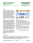
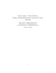
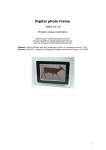
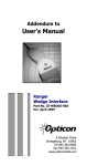
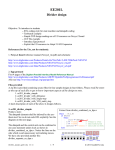
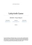
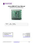
Aircraft Combat A mini game Yun Miao Siyu Tan [email protected] [email protected] 16/10/2013 ABSTRACT This report documents the development of an aircraft combat game. In this project, the game is implemented on Digilent Nexys 3 FPGA Board with a VGA monitor and a custom designed GPIO joy stick. The custom graphic accelerator is designed in VHDL to generate the game video and output to the VGA monitor, while game logic software developed on MicroBlaze processor handles the game information and allows the user to play the game via an interrupt based joy stick connected through GPIO on board. The game output resolution is 640x480 pixels @ 60 Hz. 1 CONTENT ABSTRACT...................................................................................................................................................... 1 CONTENT ....................................................................................................................................................... 2 1. Introduction ........................................................................................................................................ 3 1.1. Overall design................................................................................................................................... 3 1.2. Changes from project proposal........................................................................................................ 3 2. Equipment .......................................................................................................................................... 3 3. Specifications ...................................................................................................................................... 4 4. Hardware ............................................................................................................................................ 4 4.1. Hardware Connection ...................................................................................................................... 5 4.2. Graphic accelerator .......................................................................................................................... 5 4.2.1. software configurable registers................................................................................................ 5 4.2.2. Background module ................................................................................................................. 6 4.2.3. Foreground module .................................................................................................................. 6 4.2.5. VGA_REF_COMP module ......................................................................................................... 6 4.3. 7-Segment LED display ..................................................................................................................... 8 4.4. GPIO input ........................................................................................................................................ 8 5. Software............................................................................................................................................ 12 5.1. Display objects ............................................................................................................................... 12 5.2. Initialize and move objects ............................................................................................................ 13 5.2.1. Initialize and move enemies ................................................................................................... 13 5.2.2. Initialize and move player’s aircraft ....................................................................................... 14 5.3. Collision detection.......................................................................................................................... 14 5.4. Live, score and level ....................................................................................................................... 15 5.5. Other effects .................................................................................................................................. 16 6. Conclusions and discussions ............................................................................................................. 16 6.1. Possible improvements .................................................................................................................. 16 6.2. Contributions ................................................................................................................................. 16 7. References ........................................................................................................................................ 17 8. User manual:..................................................................................................................................... 17 2 1. Introduction 1.1.Overall design The idea of this project is to design an Aircraft combat game. The user can control an aircraft by using joy stick. The aircraft is flying in a two dimension vertical scrolling space. There will be enemies coming from top side of the space. The player must avoid them or destroy them by using the auto firing cannon on the aircraft. These objects will be displayed on a VGA monitor controlled by FPGA board. Also the 7-segment display is used to display some game related values such as level and speed of the aircraft. The design consists of a general purpose CPU ---- Microblaze on the FPGA board, and a graphic accelerator. In this project, AXI bus is used. The CPU decides the content to be displayed while the graphic accelerator draws the content on the screen. The final game outlook as shown in Figure 5. Figure 1 Hardware block diagram 1.2.Changes from project proposal As the game is a mini one, and for simplifies the design, BRAMs are not used. All objects are stored in the VGA accelerator using distribute memory. Instead of PLB bus, the game is implemented using AXI bus. The C program is not interrupted every frame, it is looping with a delay and in the following of this report, LT stands for loop time indicate the time for one loop of the while statement in C program. The program is only interrupted by the direction control from joy stick. 2. Equipment In this project, the following equipment was used: 3 Digilent Nexys™3 Spartan-6 FPGA Board Digilent PmodA – Joy stick VGA monitor PC computer running Xilinx EDK v.14.2 To run the system, the following equipment was need: Digilent Nexys™3 Spartan-6 FPGA Board Digilent Adept, to program the board Digilent PmodA - Joy stick VGA monitor 3. Specifications The system was able do the following: Output graphics to a VGA monitor with a resolution of 640x480 pixels @ 60Hz. Update the player’s position by moving the joy stick. Update the game with enemy aircrafts at different times Detect collisions between the player’s aircraft and enemy aircrafts. And in a similar way detect collisions between the bullet shot by the player and enemy aircraft. 4. Hardware Figure 2 System assembly view 4 4.1.Hardware Connection In our hardware connection, we used AXI bus connection. The AXI bus is a newer version and could provide more functions than old PLB bus. We used BRAM in the processor to store the figures. We also used GPIO resources provided by Xilinx. To monitor the situation of the GPIO, we added am interrupt module in our design. It can sense the activities of the GPIOs. The system assembly view is shown in Figure 2. 4.2.Graphic accelerator To make the background smother and make software design easier, we put the foreground display, background generation and score-live display in to an individual VGA_ACC module. It is composed by VHDL, which is called by the ‘user_logic’ module generated by ‘Create or Import Peripheral’ function in XPS. The module provided 10 software configurable registers, which can be accessed by software and change the display contents in hardware. The Block diagram can be seen in Figure 3. VGA _AC USER_LOGIC software configurable registers VGA_TOP BACKGROUND BIN_BCD ----LIVE VGA_REF_COMP BIN_BCD ----CORE FOREGROUND Figure 3 VGA accelerator VHDL block diagram 4.2.1. software configurable registers To access the hardware of VGA accelerator, we need to use the software configurable registers. Each of them is a 32-bit register, and the value defined in software can be seen in the hardware. So hardware core can use these values to change the position of various objects, or update the score and live on the display. The way how these registers communicate with the software is predefined in the user_logic template, so we could easily pass the value from the resisters to our top module inputs. Register list is in list 1. 5 Plane position(x,y) Enemy position1(x,y) Enemy position2(x,y) Enemy position3(x,y) Enemy position4(x,y) Bullet position(x,y) Lives Score Reg0(26-16), Reg0(10-0) Reg1(24-16), Reg1(8-0) Reg2(24-16), Reg2(8-0) Reg3(24-16), Reg3(8-0) Reg4(24-16), Reg4(8-0) Reg5(24-16), Reg5(8-0) Reg6(25-16) Reg6(9-0) List 1 software configurable registers and corrseponding VGA moudle input 4.2.2. Background module The background module only handles the background objects---in our case is the flying cloud and the background color. We put the cloud figure in the LUT in VHDL, and when the Hcount and Vcount counting to the correct point, the cloud is ouput through VGA line to the monitor pixel by pixel. To control the movement of the cloud, we defined a counter to count the current vertical place of the cloud. And at each refreshing, the counter added by one and the cloud can move down one line. Because the refreshing rate is 60fps, so in this way the background cloud moving smoothly. We also need to design the sky space where the plane can fly in blue, and the gray surroundings. 4.2.3. Foreground module The foreground generator takes care of the airplane and enemies, which positions are loaded from software accessible registers. So the location of both plane and enemies can be calculated by our software. In our hardware, we only designed four enemy position inputs. It means that in one screen, only maximum 4 enemies can be shown. That is because we need to control the position of each enemy in real time to allow the movement speed controlling in software part. In this way the input enemy position should be a limit number. However, when one enemy is shot, another one will emerge soon. So when the game starts, due to the various place and speed of showing up enemy, you can hardly think this number limitation is a problem. 4.2.4. BIN_BCD module Two BIN_BCD modules control the scores or lives to be display on the display, the binary value should be converted to BCD value. We used the classical add-3 algorithm, it is a pure combinational logic which is fast and easy to implement. The module can input 10-bit binary, and converts to 3 BCD numbers, which requires 12-bit output in total. 4.2.5. VGA_REF_COMP module The VGA_REF_COMP module handles the timing sequence of VGA display, provides the horizontal and vertical counters to guide other blocks generate correct output to the VGA connector. It uses a 25MHz clock signal, to generate the HSYNC and VSYNC signal and two counters to count the clock. When the H-counter or V-counter lies out of the visible area, a blank signal is generated. When H-counter is counted to the end, it resets to 0 and V-counter increased by 1. The timing diagram is shown in Figure 4[1]. The other modules should receive these two 6 counter signals, and generate the correct pixel to the VGA connector at each clock cycle. When they detected the blank signal, a black signal (000) should be outputted. The screenshot of our game interface is shown in Figure 5. Figure 4 Timing sequence of VGA controller [1] Figure 5 Final gameplay screen shot 7 4.3.7-Segment LED display The Nexys3 board contains a four-digit common anode seven-segment LED display. We used this on-board LED display to show the current level, bullet speed and movement speed. The hardware design is just using an IP provided by Digilent, so we simply connected it to our system and it works. The IP has the soft controllable registers, so the software part of our system can control the content to be shown on the display. The display will scan itself, and shows the corresponding values. 4.4. GPIO input Figure 6 Joystick controller schematic To control the movement of our plane, we designed a joystick which can be connected to the board. The NEXYS-3 board provided some P_MOD connectors that can be used as GPIO. Inside the joystick, we added one comparator circuit to measure the direction of the handle, because the original joystick only provided two potentiometers. And to generating the interrupt when moving the handle, a NE555 timing circuit is added. It can generate square wave signal which frequency is adjustable, thus could control the speed of interrupt generation. Figure 6 plots the schematic of our circuits and Figure 7 is the inside view of the joystick. 8 Figure 7 Inside the joystick We added a vibration module to make the game more realistic. It is just a small motor with a tiny heat sink as the vibration module. When the input signal is high, it will power on by the internal battery and generate the vibration effect in your hand, which is so cool! The picture is shown in Figure 8. 9 Figure 8 Vibration module inside the handle The P-mod connectors are designed for connecting external hardware components. In Nexys 3 board, four groups of P-mod connectors are provided, as demonstrated in figure 9. We used Pmod-A for our Joystick input. JA1-JA4 are for four directions of the Joystick, JA7 is for vibration output, JA8 and JA9 are two buttons input on the handle. It could be configured in the XPS hardware platform, and can also be connected to the interrupt module. The whole system is illustrated in figure 10. The controller has four directions, which could control the movement of the plane. There is a small screw on the left, which is designed to adjust the frequency of the interrupt frequency. The green button is used to switch the vibration module, which can reduce the noise when debugging our program. The top button on the handle is used to control the movement speed of the plane, and the button placing at finger could control the bullet speed. The Joystick is connected to the Nexys 3 board by our customized 12-pin connector. 10 Figure 9 PMOD connectors on Nexys 3 board [1] Customized Connector Adjustment Screw Vibration Switch Figure 10 The whole hardware system The device utilization is shown in list 2. Because we use distributed memory in VHDL, so the usage of BRAM is quite low. 11 Slices LUTs Slice Registers Used as Memory Used Available 3,847 9,112 Utilization (%) 42 2,511 18,224 13 156 2176 7 List 2 Device Utilization in Nexys-3 fpga board 5. Software All software is written in C. It is responsible for information in foreground, including position of player and enemy, position of bullet, check if there’s been any change in joy stick state, and handling collision of objects in foreground. 5.1.Display objects In our game, software doesn’t output the actual data of pixels. Instead, all pixel data of a picture is drew by hardware VGA accelerator, while software gave hardware the position data of a certain picture. The dimensions of the game window and objects are as Figure 11. Figure 11 Dimensions of the game window and objects 12 There are four kinds of objects need to be display on the screen: player’s aircraft, enemies, bullet and lives & scores. Each of them is handled by a function: Display_flight: The function display_flight is used to write the position data of player’s aircraft to the slave registers. Display_enemy: Function display_enemy is used to write the data, in which includes position and speed, of a certain enemy to the slave registers. The initial x-position of enemy is determined by an array of random numbers which is generated in Matlab in advance. However, y-position of enemy plane is calculated in this function to keep the enemy going down at the given speed. Details of position calculation will be introduced later. Display_bullet: Similar to display_flight function, display_bullet writes position data of the bullet shot by the player’s aircraft to the slave register. Display_lives_score: send data of lives remaining and score gained to the slave register. 5.2. Initialize and move objects 5.2.1. Initialize and move enemies Apart from the functions manage to display objects, there are several functions called for operating the game. For example, make the game seems more random. To be more like a game, the enemy should show up randomly, random in x-position and random in time with random speed. In order to do so, we have a function called enemy_showup to implement the randomly showing up in time and some if cases in main to handle random position and speed. The random we carried out is pseudo random which base on three set of arrays where stored the random number generated in Matlab in advance. For x-position, 300 random numbers are stored in rand_pos[] in range from 1 to 288. This is because the width of the game window is 320, while the width of enemy is 32, and upper-left corner is regarded as original point. For random speed of enemy, 100 random number are stored in rand_speed[] in range from 1 to 3. The speed value determines how many pixels the enemy moves in one loop time. For random delay before next show up of the enemy, 200 random number are stored in rand_wait[] in range from 1 to 500. The wait time determines the clock cycles before next show up. The “if case”, as show in List 3, first decide which enemy to be activate and take number one by one from both rand_pos[] and rand_speed[] with the help of a counter. Then send the value to display_enemy function to display. if(enemy1_y==1) { pos_cnt=pos_cnt<pos_length?pos_cnt+1:0; speed_cnt=speed_cnt<speed_length?speed_cnt+1:0; 13 enemy1_x = rand_pos[pos_cnt]; speed1 = rand_speed[speed_cnt]; } List 3 “if case” for enemy set up After the enemy flies out of the screen or be eliminated, it should show up after the delay. This is handled by function enemy_showup the function first read a value from rand_wait[] and count down from the value read till 0, then again enable display_enemy again. 5.2.2. Initialize and move player’s aircraft The player’s aircraft is initialized in the middle bottom position. The movement of the aircraft is implemented by an interrupt. Every movement on the joy stick will trigger the interrupt. With the different signals of direction, the aircraft is moved certain pixels according to integer speed. The bullet is shot from the head of aircraft, the speed of bullet is determined to be either 15 pixels/LT or 30 pixels/LT according to the state of button on the joy stick. Then display_bullet is called. When the player’s aircraft is crash on the enemy, the aircraft will blink to indicate dead. Function blink is called to implement blink. To make the aircraft disappear is to write zeros to slave registers which controls the display of player’s aircraft. Whole blink duration last for 80 clock cycles and blink twice. 5.3. Collision detection The collision of bullet shot on enemy and player’s aircraft crash on enemy are handled by two “if case” in main function. As all objects are considered as squares while upper-left corner is original point, collision detection can be easily done by comparing the position of objects. But for better detection, enemy is considered as shown in Figure 12 and player’s aircraft is the same as enemy but upsidedown Figure 13: Figure 12 Enemy shape for collision detection Figure 13 Player’s aircraft shape 14 Collision of enemy and player’s aircraft is detected as Figure 14. In the figure, the green frame indicates the boundary of the aircraft’s original point. When the original point is inside the green frame, enemy and the aircraft is considered crash with each other. So the “if case” is designed like List 4. In the list, x_pos and y_pos are the position of player’s aircraft, enemy1_x and enemy1_y are the position of the enemy: if((y_pos<x_pos-enemy1_x+32+enemy1_y && y_pos<32+enemy1_xx_pos+enemy1_y) && (x_pos<enemy1_x+32 && x_pos>enemy1_x-32 && y_pos>enemy1_y-20 && y_pos<enemy1_y+20)) { enemy1_y=0; live-=1; } List 4 "if case" for collision detection of enemy and aircraft Figure 14 enemy and aircraft collision detection The collision of bullet and enemy is easier as bullet flies fast, the collision can be detect using only the square of enemy and the rectangular of bullet. 5.4. Live, score and level In the game, player will have 5 lives. Lives will decrease when aircraft crash on enemy. When live becomes zero, the scores gained will decrease continuously to zero, while live increase back to five. 15 The counting of score is related with level. In level 1, every shot on enemy will add 1 to score, with each increase of level, the scores gained at each shot increases by one. Level will go up when score reaches 50, 150, 250… and the game speed will be faster. 5.5. Other effects Vibration of the joy stick: when the vibration function is turned on, each time shot on an enemy, the joy stick will vibrate for a short time. Each time the aircraft crashes, there will be a long time vibration. As the joy stick is connected to the GPIO on the board, to vibrate is just discrete write certain value to the specific pin on GPIO, ‘1’ for vibrate, ‘0’ for not vibrate. Aircraft boost: when pressing the upper button on the joy stick the player’s aircraft can have a faster moving speed, as speed is changed from 5 pixels/LT to 10 pixels/LT. This is controlled in main function. Aircraft shooting boost: when the lower button is pressed, the bullet speed will change from 15 pixels/LT to 30 pixels/LT. This is controlled in main function. 6. Conclusions and discussions In the project, the game was built successfully and the game play logic was good but not perfect. During gaming, the enemies came into the screen randomly. It felt like there were more than 4 enemies at a time in the screen because of the speed. There were still some small bugs that sometimes the bullet couldn’t hit on the enemy. We think the reason is that the bullet flew 15 pixels/LT or 20 pixels/LT while the height of the enemy is 32 pixels. When the speed of the enemy is fast enough, the bullet won’t hit on it. 6.1. Possible improvements First of all, the graphic can be improved by introducing BRAM into the system which can store more complex pictures. But the problem of smooth scrolling needs to be solved. More enemies could be added, not only in quantity but also in type, even bosses could be introduced. We’ve think about adding sound module, but as the time is limited, we didn’t work it out. 6.2. Contributions During the project, Tan Siyu is mainly in charge of the hardware design including the VHDL coding, the built up of the joystick as well as hardware test. On the other hand, Miao Yun is focusing on the software coding and the graphic for the objects. 16 7. References [1]Digilent Nexys 3 manuals and drivers: http://www.digilentinc.com/Products/Detail.cfm?NavPath=2,400,897&Prod=NEXYS3 [2]Project 2012 TowerDefence http://cs.lth.se/english/course/eda385-design-of-embeddedsystems-advanced-course/archive/projects-2012/ 8. User manual: To play the game, plug in the USB connector to the board, connect the joy stick to the Pmod connector according to the direction indicated on the connector of the joy stick. In the screen, the green aircraft flying upward is the player’s aircraft, while all enemies are flying downwards. Player’s aircraft will shoot bullet automatically, bullet can eliminate enemy, while player’s aircraft will crash on the enemies. Every enemy killed will add some bonus to the final score, at level 1, the bonus is 1. Level 2 leads to 2 bonus, etc. When score reaches 50, 150,250… the level increase. Player will have 5 lives at beginning, each crash on enemy will decrease 1 live until live become 0 then game over. The player can control the aircraft by using the joy stick, by pressing the finger button on the joy stick, the bullet speed increases. Keep pressing the upper button, the moving speeding of the player’s aircraft increases. The green button on the base of the joy stick is for turning on and off the vibration of the joy stick. 17